EP1663570B1 - Vormontagevorrichtung für schneidringgarnitur - Google Patents
Vormontagevorrichtung für schneidringgarnitur Download PDFInfo
- Publication number
- EP1663570B1 EP1663570B1 EP04767069A EP04767069A EP1663570B1 EP 1663570 B1 EP1663570 B1 EP 1663570B1 EP 04767069 A EP04767069 A EP 04767069A EP 04767069 A EP04767069 A EP 04767069A EP 1663570 B1 EP1663570 B1 EP 1663570B1
- Authority
- EP
- European Patent Office
- Prior art keywords
- cutting ring
- socket
- support means
- ring fitting
- movable actuator
- Prior art date
- Legal status (The legal status is an assumption and is not a legal conclusion. Google has not performed a legal analysis and makes no representation as to the accuracy of the status listed.)
- Expired - Lifetime
Links
Images

Classifications
-
- B—PERFORMING OPERATIONS; TRANSPORTING
- B25—HAND TOOLS; PORTABLE POWER-DRIVEN TOOLS; MANIPULATORS
- B25B—TOOLS OR BENCH DEVICES NOT OTHERWISE PROVIDED FOR, FOR FASTENING, CONNECTING, DISENGAGING, OR HOLDING
- B25B27/00—Hand tools, specially adapted for fitting together or separating parts or objects whether or not involving some deformation, not otherwise provided for
- B25B27/02—Hand tools, specially adapted for fitting together or separating parts or objects whether or not involving some deformation, not otherwise provided for for connecting objects by press fit or detaching same
- B25B27/06—Hand tools, specially adapted for fitting together or separating parts or objects whether or not involving some deformation, not otherwise provided for for connecting objects by press fit or detaching same inserting or withdrawing sleeves or bearing races
- B25B27/064—Hand tools, specially adapted for fitting together or separating parts or objects whether or not involving some deformation, not otherwise provided for for connecting objects by press fit or detaching same inserting or withdrawing sleeves or bearing races fluid driven
-
- Y—GENERAL TAGGING OF NEW TECHNOLOGICAL DEVELOPMENTS; GENERAL TAGGING OF CROSS-SECTIONAL TECHNOLOGIES SPANNING OVER SEVERAL SECTIONS OF THE IPC; TECHNICAL SUBJECTS COVERED BY FORMER USPC CROSS-REFERENCE ART COLLECTIONS [XRACs] AND DIGESTS
- Y10—TECHNICAL SUBJECTS COVERED BY FORMER USPC
- Y10T—TECHNICAL SUBJECTS COVERED BY FORMER US CLASSIFICATION
- Y10T279/00—Chucks or sockets
- Y10T279/17—Socket type
- Y10T279/17231—Pivoted jaws
- Y10T279/17239—Moving-cam actuator
- Y10T279/17256—Reciprocating cam sleeve
-
- Y—GENERAL TAGGING OF NEW TECHNOLOGICAL DEVELOPMENTS; GENERAL TAGGING OF CROSS-SECTIONAL TECHNOLOGIES SPANNING OVER SEVERAL SECTIONS OF THE IPC; TECHNICAL SUBJECTS COVERED BY FORMER USPC CROSS-REFERENCE ART COLLECTIONS [XRACs] AND DIGESTS
- Y10—TECHNICAL SUBJECTS COVERED BY FORMER USPC
- Y10T—TECHNICAL SUBJECTS COVERED BY FORMER US CLASSIFICATION
- Y10T279/00—Chucks or sockets
- Y10T279/18—Pivoted jaw
- Y10T279/185—Internal-cone actuated
-
- Y—GENERAL TAGGING OF NEW TECHNOLOGICAL DEVELOPMENTS; GENERAL TAGGING OF CROSS-SECTIONAL TECHNOLOGIES SPANNING OVER SEVERAL SECTIONS OF THE IPC; TECHNICAL SUBJECTS COVERED BY FORMER USPC CROSS-REFERENCE ART COLLECTIONS [XRACs] AND DIGESTS
- Y10—TECHNICAL SUBJECTS COVERED BY FORMER USPC
- Y10T—TECHNICAL SUBJECTS COVERED BY FORMER US CLASSIFICATION
- Y10T279/00—Chucks or sockets
- Y10T279/33—Member applies axial force component
Definitions
- the invention relates to premounting devices for a cutting ring fitting according to the preamble of claim 1.
- Such a device is known from DE 38 43 450 .
- a known premounting device for a cutting ring fitting comprises a device frame, which includes a socket means and means for moving the socket means as well as support means arranged to be attached to the device frame.
- the support means comprise a substantially U-shaped recess, in which a pipe can be placed.
- the socket means comprise a socket, whose inner diameter is larger than the outer diameter of the pipe and whose inner surface is arranged to give the cutting ring a desired shape.
- the cutting ring fitting When the cutting ring fitting is premounted with the above-described device, the cutting ring and a corresponding nut are placed on the outer surface of the pipe close to a pipe end.
- the pipe end is set in the premounting device of the cutting ring such that the cutting ring and the corresponding nut are substantially between the support means and the device frame, the nut on the side of the support means.
- the socket means is displaced hydraulically, for instance, outwardly from the device frame such that the cutting ring is sandwiched between the socket means and the nut, whereby the cutting ring is shaped in a desired manner.
- the above arrangement has a drawback that it requires several different support means with the U-shaped recess to correspond to different outer diameters of the pipes and the nuts arranged thereto. So, if the pipe on which the cutting ring fitting is to be premounted has a diameter that differs from that of the previous pipe, on which a cutting ring fitting was premounted, the support means must be changed. It is difficult and time-consuming to use this kind of a premounting device for a cutting ring fitting. Moreover, loose support means may be lost.
- the object of the invention is to provide a premounting device for a cutting ring fitting, by which the above-mentioned problems can be solved. This is achieved with a premounting device for a cutting ring fitting, which is characterized by what is disclosed in the independent claim. The preferred embodiments are disclosed in the dependent claims.
- the invention is based on the idea that support means are arranged to be radially adjustable and in operational connection with a socket means so as to provide said adjustment.
- the premounting device for the cutting ring fitting according to the invention has an advantage that it enables premounting of cutting ring fittings on pipes of different diameters without support means changes. Another advantage is that it is easy to use, which results from the fact that the motion of the socket means controls the position of the support means automatically.
- Figures 1A and 1B show a prior art premounting device for a cutting ring fitting. It appears from Figure 1A that support means 2 connected to a frame part 1 comprise a substantially U-shaped recess, in which a pipe can be placed. Figure 1B also shows a nut 5 and a cutting ring 6 that are set on the outer surface of the pipe for the premounting of the cutting ring fitting.
- the cutting ring 6 is given a desired shape by moving a movable actuator 3 outwardly from the frame part 1, whereby the cutting ring 6 is sandwiched between a socket means 10 connected to the movable actuator 3 and the nut 5 supported by the support means 2.
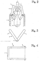
- Figure 2 is a partial view of an embodiment of a premounting device for a cutting ring fitting according to the invention, which comprises a frame part 1, support means 2, a movable actuator 3 and means for moving the movable actuator 3.
- Figure 1B showing the prior art
- Figure 2 also shows a socket means 10 connected to the movable actuator 3 and a nut 5 and a cutting ring 6, which are set on the outer surface-of a tubular element 4 for the premounting of the cutting ring fitting.
- the support means 2 comprise two jaw parts 7 hinged to the frame part by means of hinges 8, which jaw parts are capable of turning between open and closed positions. In the open position the tips of the jaw parts 7 are wide apart and in the closed position the tips of the jaw parts 7 are close to, or in contact with, the outer surface of the tubular element 4 locating between the jaw parts. It depends, for instance, on the outer diameter of the nut 5 used, how close to the outer surface of the tubular element 4 the tips of the jaw parts 7 of the support means 2 should be when the cutting ring fitting is premounted.
- the support means 2 of the device in Figure 2 comprise operating protrusions 12 that are arranged to be in operational connection with the socket means 10 in order to provide radial adjustment of the support means 2.
- Each operating protrusion 12 forms an integral member with a respective jaw part 7 and extends substantially on the other side of the hinge 8 than the respective jaw part 7.
- the device of Figure 2 is provided with spring means 14, which tend to turn the support means 2 to the open position.
- the cutting ring 6 and the nut 5 are set on the outer surface of the tubular element 4, close to the end of the element, such that the cutting ring 6 is closer to that end of the tubular element 4 on which the cutting ring fitting is to be premounted.
- the movable actuator 3 Prior to mounting the movable actuator 3 is in its rest position close to the frame part 1, whereby the operating protrusions 12 of the support means 2 come into contact with a slim middle portion of the socket means 10.
- the support means 2 When the operating protrusions 12 of the support means 2 come into contact with the slim middle portion of the socket means 10, the support means 2 are in their open position and the tips of the jaw parts 7 are wide apart, which facilitates the setting of the pipe portion equipped with the nut 5 and the cutting ring 6 between the support means 2 and the socket means 10.
- the end of the tubular element 4 is set adjacent to the socket means 10 connected to the movable actuator 3 such that the tubular element 4 and the socket means 10 are substantially coaxial.
- the movable actuator 3 will be moved outwardly from the frame part 1.
- the socket means 10 connected thereto moves along.
- the root of the socket means 10 is larger in diameter than the middle portion of the socket means 10, a change in diameter taking place gradually.
- the diameters of the middle portion and the root are of importance only at points where the socket means is arranged to be in operational connection with the support means 2.
- the contact points of the operating protrusions 12 of the support means 2 and the socket means 10 transfer from the slim middle portion of the socket means 10 to the root portion that is larger, whereby the support means 2 pivot on the hinges 8 towards the closed position.
- the support means are in their closed position.
- the socket means 10 is further moved outwardly with respect to the frame part 1. Shaping of the cutting ring 6, while sandwiching it between the socket means 10 and the nut 10, takes place in the corresponding manner as in prior art premounting devices.
- the movable actuator 3 is moved back to its rest position, whereby the spring means 14 turn the support means 2 into their open position and the pipe portion equipped with the premounted cutting ring fitting can be removed from between the support means 2 and the socket means 10.
- the socket means 10 is arranged to cooperate with the support means 2 such that to move the socket means 10 towards the frame part 1 forces the support means 2 in their open position.
- the socket means 10 of the premounting device for the cutting ring fitting shown in Figure 2 is an integral member, which comprises a socket arranged for shaping the cutting ring 6.
- a specific socket means 10 that comprises a socket specially adapted for the pipe size concerned.
- the body of the socket means 10, i.e. the part with which the operating protrusions 12 of the support means are in contact so as to provide radial adjustment, can be shaped differently for different pipe sizes, whereby the open position and the closed position of the support means 2 are different for pipes of different sizes.
- the bodies of the socket means 10 arranged for pipes of different sizes are shaped such that the diameters of the middle portion and the root of the socket means 10 of a large pipe are relatively small, and the diameters of the middle portion and the root of the socket means 10 of a small pipe are relatively large.
- both the open position and the closed position of the support means 2 are wider than in the case of a small pipe.
- the tips of the jaw parts 7 of the support means are both in the open position and in the closed position of the support means 2 wider apart from each other in the case of a large pipe than in the case of a small pipe.
- the socket means 10 intended for different pipe sizes can be designed such that only the closed positions of the support means 2 differ from one another, whereby in the open position of the support means 2 the tips of the jaw parts 7 are equally wide apart both in the case of large pipes and in the case of small pipes.
- the socket means 10 can be provided such that it comprises a body, which is in operational connection with the support means 2 to provide radial adjustment of the support means, and a socket part, which is detachably attached to said body.
- the socket part is changed when the pipe size changes, and the socket part may be the same as those used in prior art premounting devices for cutting ring fittings.
- Different open and closed positions of the support means 2 for different pipe sizes can also be achieved with a socket means 10, whose body is the same for all pipe sizes. This is achieved, for instance, by arranging the body of the socket means 10 to be rotatable and by shaping said body such that its diameter is different measured at different points of its periphery.
- the body of the socket means 10 is turned to a position, in which the operating protrusions 12 of the support means 2 come into contact with the point where the diameter of the body of socket means 10 is small.
- the body of the socket means-10 is turned to a position, in which the operating protrusions 12 of the support means 2 come into contact with the point where the diameter of the body of socket means 10 is large.
- the above-mentioned rotatability of the body of the socket means 10 can be provided by the structure of the frame 1 of the premounting device for the cutting ring or that of the body of the socket means 10.
- FIG. 2 shows an alternative embodiment seen from the direction of the slewing axis of the hinge 8.
- the jaw parts 7 are hinged such that their slewing axes coincide, i.e. both of the jaw parts 7 turn about the same axis.
- Figure 4 shows one jaw part 7 of Figure 3 seen from a direction that is perpendicular to the slewing axis of the hinge 8.
- the jaw part 7 is substantially U-shaped such that the slewing axis passes close to the tips of the U-prongs.
- Figures 3 and 4 do not show the operating protrusions of the support means 2.
- the working pressure need not necessarily be adjustable. Suitable pressing for the cutting ring 6 can be achieved, for instance, by shaping the socket means 10 intended for different pipe sizes to be different in length. By changing the length of the socket means 10 it is possible to extend the pressing effect at different distances from the frame part 1 by standard working motion of the movable actuator 3.
- the pipes, the cutting rings and the nuts used for mounting must be substantially standard in dimensions. For instance, using a nut that is thinner than normal may have a result that the cutting ring 6 is not pressed into a desired shape by a standard working motion of the movable actuator 3.
- the support means 2 of the premounting device for the cutting ring fitting according to the invention may comprise centring means, by which it will be ensured that the tubular element 4 as well as the nut 5 and the cutting ring 6 set on the outer surface thereof are positioned coaxially with the socket means 10 as the cutting ring fitting is premounted.
- the centring means may comprise substantially U-shaped notches-provided at the tips of the jaw parts 7.
- the premounting device is a portable device, whose frame part 1 in view of working characteristics is shaped substantially similar to a typical cordless power drill.
- This device can be arranged for use in connection with pipes whose outer diameter is about 6 to 42 mm, for instance.
- the premounting device for the cutting ring fitting according to the invention is primarily intended for premounting cutting ring fittings on metal pipes.
Landscapes
- Engineering & Computer Science (AREA)
- Mechanical Engineering (AREA)
- Automatic Assembly (AREA)
- Polishing Bodies And Polishing Tools (AREA)
- Preliminary Treatment Of Fibers (AREA)
- Mechanical Coupling Of Light Guides (AREA)
- Manufacturing Of Electrical Connectors (AREA)
Claims (5)
- Vormontagevorrichtung für einen Schneidringanschluss, welche Vorrichtung einen Rahmenteil (1), Stützmittel (2), ein bewegliches Arbeitsglied (3), Mittel zum Bewegen des beweglichen Arbeitsglieds (3) und ein am beweglichen Arbeitsglied (3) lösbar befestigtes Hülsenmittel (10) aufweist, welches bewegliche Arbeitsglied (3) angeordnet ist, sich vom Rahmenteil (1) nach aussen zu bewegen, wobei die Stützmittel (2) und das Hülsenmittel (10) angeordnet sind, zusammenzuwirken, so dass eine Mutter (5) und ein Schneidring (6) auf der Aussenfläche eines rohrförmigen Elements (4) zwischen den Stützmitteln (2) und dem Hülsenmittel (10) gegeneinander gedrückt werden, um einen Schneidringanschluss vorzumontieren, dadurch gekennzeichnet, dass die Stützmittel (2) radial einstellbar und in funktionaler Verbindung mit dem Hülsenmittel (10) angeordnet sind, um die besagte Einstellung zustande zu bringen.
- Vormontagevorrichtung für einen Schneidringanschluss nach Anspruch 1, dadurch gekennzeichnet, dass das Hülsenmittel (10) derart ausgestaltet ist, dass, wenn sich das bewegliche Arbeitsglied (3) in seiner Ruhestellung nahe dem Rahmenteil (1) befindet, das Hülsenmittel (10) den Stützmitteln (2) erlaubt, sich in ihrer Offenstellung zu befinden, und wenn das bewegliche Arbeitsglied (3) von seiner Ruhestellung um eine vorbestimmte Entfernung nach aussen in Bezug auf den Rahmenteil (1) verschoben wird, das Hülsenmittel (10) die Stützmittel (2) zwingt, sich in ihre Schliessstellung zu bewegen.
- Vormontagevorrichtung für einen Schneidringanschluss nach Anspruch 2, dadurch gekennzeichnet, dass der mittlere Teil des Hülsenmittels (10) einen kleineren Durchmesser als der Fuß des Hülsenmittels (10) hat und dass, wenn sich das bewegliche Arbeitsglied (3) in seiner Ruhestellung befindet, die Stützmittel (2) in funktionaler Verbindung mit dem mittleren Teil des Hülsenmittels (10) sind, und wenn das bewegliche Arbeitsglied (3) um die besagte vorbestimmte Entfernung nach aussen in Bezug auf den Rahmenteil (1) verschoben wird, die Stützmittel (2) in funktionaler Verbindung mit dem Fuß des Hülsenteils (10) sind.
- Vormontagevorrichtung für einen Schneidringanschluss nach einem der vorhergehenden Ansprüche, dadurch gekennzeichnet, dass das Hülsenmittel (10) ein integrales Glied ist, das eine Büchse aufweist, die angeordnet ist, den Schneidring (6) zu gestalten.
- Vormontagevorrichtung für einen Schneidringanschluss nach einem der vorhergehenden Ansprüche, dadurch gekennzeichnet, dass sie Federmittel (14) aufweist, die die Stützmittel (2) gegen die Offenstellung zwingen.
Applications Claiming Priority (2)
| Application Number | Priority Date | Filing Date | Title |
|---|---|---|---|
| FI20031373A FI115202B (fi) | 2003-09-23 | 2003-09-23 | Leikkausrengasliittimen esiasennuslaite |
| PCT/FI2004/000555 WO2005028155A1 (en) | 2003-09-23 | 2004-09-21 | Premounting device for cutting ring fitting |
Publications (2)
| Publication Number | Publication Date |
|---|---|
| EP1663570A1 EP1663570A1 (de) | 2006-06-07 |
| EP1663570B1 true EP1663570B1 (de) | 2009-05-13 |
Family
ID=27839035
Family Applications (1)
| Application Number | Title | Priority Date | Filing Date |
|---|---|---|---|
| EP04767069A Expired - Lifetime EP1663570B1 (de) | 2003-09-23 | 2004-09-21 | Vormontagevorrichtung für schneidringgarnitur |
Country Status (7)
| Country | Link |
|---|---|
| US (1) | US7694979B2 (de) |
| EP (1) | EP1663570B1 (de) |
| AT (1) | ATE431219T1 (de) |
| DE (1) | DE602004021118D1 (de) |
| ES (1) | ES2327046T3 (de) |
| FI (1) | FI115202B (de) |
| WO (1) | WO2005028155A1 (de) |
Families Citing this family (2)
| Publication number | Priority date | Publication date | Assignee | Title |
|---|---|---|---|---|
| DE102009000264A1 (de) * | 2009-01-16 | 2010-07-22 | Hilti Aktiengesellschaft | Haltevorrichtung für Befestigungsmittel |
| CN101898340A (zh) * | 2009-05-25 | 2010-12-01 | 鸿富锦精密工业(深圳)有限公司 | 螺丝起子 |
Family Cites Families (16)
| Publication number | Priority date | Publication date | Assignee | Title |
|---|---|---|---|---|
| US2007521A (en) * | 1935-07-09 | Adapter | ||
| US668928A (en) * | 1900-11-08 | 1901-02-26 | William Phillips Parsons | Bottle-finishing machine. |
| US1486467A (en) * | 1921-05-28 | 1924-03-11 | Chrome Steel Works | Workholder for screw-threading machines |
| US3998467A (en) * | 1975-08-19 | 1976-12-21 | Tony Petkovich | Tool chuck for a drill press |
| DE3202266C2 (de) * | 1982-01-12 | 1986-02-06 | Bell-Hermetic-Armaturenwerk GmbH & Co KG, 3509 Spangenberg | Hydropneumatisches Vormontagegerät für lötlose Rohrverschraubungen |
| DE3843450A1 (de) | 1988-12-23 | 1990-06-28 | Meike Froehlich | Verfahren und vorrichtung zum vormontieren eines schneidrings oder keilrings einer rohrverschraubung |
| KR920009967B1 (ko) * | 1990-11-01 | 1992-11-09 | 삼성전자 주식회사 | 선삭 가공물의 크램핑장치 |
| DE4431112C1 (de) | 1994-09-01 | 1996-04-11 | Walterscheid Gmbh Jean | Vorrichtung zur Vormontage einer Schraubverbindung für Rohre |
| US5909911A (en) * | 1996-05-02 | 1999-06-08 | Long; James A. | Device for stabilizing a disassembly device during use |
| US6305697B1 (en) * | 1998-11-23 | 2001-10-23 | Joseph John Tebbe | Clamping jaw device |
| US6134992A (en) * | 1999-09-21 | 2000-10-24 | Perkins; Leland M. | Fasterner removing tool |
| DE10002224C1 (de) * | 2000-01-20 | 2001-09-06 | Lindner Armaturen Gmbh | Vorrichtung zur Verbindung einer Rohrleitung mit einem Rohrleitungselement mittels Klemm- oder Schneidring |
| FR2807958B1 (fr) * | 2000-04-21 | 2006-05-19 | Facom | Manchon pour outil d'extraction, outil d'extraction correspondant et procede d'extraction correspondant |
| DE10040606C2 (de) * | 2000-08-16 | 2002-06-27 | Parker Hannifin Gmbh | Hydraulisches oder pneumatisches Montagegerät |
| US6665919B1 (en) * | 2001-08-22 | 2003-12-23 | Lisle Corporation | Windshield wiper arm puller |
| DE10309133A1 (de) * | 2003-02-28 | 2004-09-09 | Hilti Ag | Haltevorrichtung für Befestigungsmittel |
-
2003
- 2003-09-23 FI FI20031373A patent/FI115202B/fi active IP Right Grant
-
2004
- 2004-09-21 AT AT04767069T patent/ATE431219T1/de not_active IP Right Cessation
- 2004-09-21 EP EP04767069A patent/EP1663570B1/de not_active Expired - Lifetime
- 2004-09-21 WO PCT/FI2004/000555 patent/WO2005028155A1/en not_active Ceased
- 2004-09-21 ES ES04767069T patent/ES2327046T3/es not_active Expired - Lifetime
- 2004-09-21 DE DE602004021118T patent/DE602004021118D1/de not_active Expired - Lifetime
- 2004-09-21 US US10/573,260 patent/US7694979B2/en not_active Expired - Fee Related
Also Published As
| Publication number | Publication date |
|---|---|
| WO2005028155A1 (en) | 2005-03-31 |
| ES2327046T3 (es) | 2009-10-23 |
| ATE431219T1 (de) | 2009-05-15 |
| FI115202B (fi) | 2005-03-31 |
| EP1663570A1 (de) | 2006-06-07 |
| US7694979B2 (en) | 2010-04-13 |
| US20070073411A1 (en) | 2007-03-29 |
| DE602004021118D1 (de) | 2009-06-25 |
| FI20031373A0 (fi) | 2003-09-23 |
Similar Documents
| Publication | Publication Date | Title |
|---|---|---|
| US5715723A (en) | Hose crimping apparatus | |
| WO2006056255A3 (de) | Roboterhand mit einer hydraulikeinheit, deren speicherraum ein variierbares ausgleichsvolumen hat | |
| EP2548703A3 (de) | Spannfutter mit bewegter Hülse, um den Netzschalter zu betätigen | |
| EP1431520A3 (de) | Befestigungssystem für eine verstellbare Schaufel und eine Ringbetätigungseinrichtung | |
| EP1623772A3 (de) | Biegeform mit einem Schraubstock zum Einspannen eines länglichen Elementes in einer Biegemaschine | |
| US5090230A (en) | Pipe expanding pliers | |
| EP1663570B1 (de) | Vormontagevorrichtung für schneidringgarnitur | |
| JP2015535490A (ja) | レンチ工具およびその製造方法 | |
| EP2942125A1 (de) | Crimpvorrichtung und crimpverfahren | |
| CA2459053A1 (en) | Tubing expansion | |
| US11142967B2 (en) | Wrench for breaking internal connections | |
| US6269675B1 (en) | Crimping tool for plastic pipe and the like | |
| CA2582386A1 (en) | A pipe joint lubrication device | |
| US5709117A (en) | Collet assembly for bending apparatus | |
| WO2007059535A2 (en) | Toggle clamp with manual horizontal and manual vertical adjustment | |
| CA2415057A1 (en) | Displacement and support device for a portable power tool | |
| DE60325512D1 (de) | Werkzeugrevolver | |
| EP0690754B1 (de) | Handgerät zum ausweiten eines rohrendes | |
| KR200197225Y1 (ko) | 파이프 절단기 | |
| EP1331421A3 (de) | Schalthebelanordnung mit klemmgeschütztem Balg | |
| AU4153399A (en) | Pipe crimping apparatus | |
| WO2004037473A3 (de) | Maschinenwerkzeug mit verstellbarer schneide | |
| CN219912230U (zh) | 一种管道检修定位辅助组件 | |
| CN222874460U (zh) | 一种角度可调的圆形水管拆装工具 | |
| KR100578474B1 (ko) | 보조 지그를 갖는 자동 엘보 컷팅기 |
Legal Events
| Date | Code | Title | Description |
|---|---|---|---|
| PUAI | Public reference made under article 153(3) epc to a published international application that has entered the european phase |
Free format text: ORIGINAL CODE: 0009012 |
|
| 17P | Request for examination filed |
Effective date: 20060329 |
|
| AK | Designated contracting states |
Kind code of ref document: A1 Designated state(s): AT BE BG CH CY CZ DE DK EE ES FI FR GB GR HU IE IT LI LU MC NL PL PT RO SE SI SK TR |
|
| DAX | Request for extension of the european patent (deleted) | ||
| GRAP | Despatch of communication of intention to grant a patent |
Free format text: ORIGINAL CODE: EPIDOSNIGR1 |
|
| RIC1 | Information provided on ipc code assigned before grant |
Ipc: B25B 27/06 20060101ALI20081103BHEP Ipc: B23P 19/04 20060101AFI20081103BHEP |
|
| GRAS | Grant fee paid |
Free format text: ORIGINAL CODE: EPIDOSNIGR3 |
|
| GRAA | (expected) grant |
Free format text: ORIGINAL CODE: 0009210 |
|
| AK | Designated contracting states |
Kind code of ref document: B1 Designated state(s): AT BE BG CH CY CZ DE DK EE ES FI FR GB GR HU IE IT LI LU MC NL PL PT RO SE SI SK TR |
|
| REG | Reference to a national code |
Ref country code: GB Ref legal event code: FG4D |
|
| REG | Reference to a national code |
Ref country code: CH Ref legal event code: EP |
|
| REG | Reference to a national code |
Ref country code: IE Ref legal event code: FG4D |
|
| REF | Corresponds to: |
Ref document number: 602004021118 Country of ref document: DE Date of ref document: 20090625 Kind code of ref document: P |
|
| REG | Reference to a national code |
Ref country code: SE Ref legal event code: TRGR |
|
| REG | Reference to a national code |
Ref country code: ES Ref legal event code: FG2A Ref document number: 2327046 Country of ref document: ES Kind code of ref document: T3 |
|
| PG25 | Lapsed in a contracting state [announced via postgrant information from national office to epo] |
Ref country code: PT Free format text: LAPSE BECAUSE OF FAILURE TO SUBMIT A TRANSLATION OF THE DESCRIPTION OR TO PAY THE FEE WITHIN THE PRESCRIBED TIME-LIMIT Effective date: 20090913 Ref country code: AT Free format text: LAPSE BECAUSE OF FAILURE TO SUBMIT A TRANSLATION OF THE DESCRIPTION OR TO PAY THE FEE WITHIN THE PRESCRIBED TIME-LIMIT Effective date: 20090513 |
|
| NLV1 | Nl: lapsed or annulled due to failure to fulfill the requirements of art. 29p and 29m of the patents act | ||
| PG25 | Lapsed in a contracting state [announced via postgrant information from national office to epo] |
Ref country code: NL Free format text: LAPSE BECAUSE OF FAILURE TO SUBMIT A TRANSLATION OF THE DESCRIPTION OR TO PAY THE FEE WITHIN THE PRESCRIBED TIME-LIMIT Effective date: 20090513 Ref country code: SI Free format text: LAPSE BECAUSE OF FAILURE TO SUBMIT A TRANSLATION OF THE DESCRIPTION OR TO PAY THE FEE WITHIN THE PRESCRIBED TIME-LIMIT Effective date: 20090513 Ref country code: PL Free format text: LAPSE BECAUSE OF FAILURE TO SUBMIT A TRANSLATION OF THE DESCRIPTION OR TO PAY THE FEE WITHIN THE PRESCRIBED TIME-LIMIT Effective date: 20090513 |
|
| PG25 | Lapsed in a contracting state [announced via postgrant information from national office to epo] |
Ref country code: CZ Free format text: LAPSE BECAUSE OF FAILURE TO SUBMIT A TRANSLATION OF THE DESCRIPTION OR TO PAY THE FEE WITHIN THE PRESCRIBED TIME-LIMIT Effective date: 20090513 Ref country code: RO Free format text: LAPSE BECAUSE OF FAILURE TO SUBMIT A TRANSLATION OF THE DESCRIPTION OR TO PAY THE FEE WITHIN THE PRESCRIBED TIME-LIMIT Effective date: 20090513 Ref country code: EE Free format text: LAPSE BECAUSE OF FAILURE TO SUBMIT A TRANSLATION OF THE DESCRIPTION OR TO PAY THE FEE WITHIN THE PRESCRIBED TIME-LIMIT Effective date: 20090513 Ref country code: DK Free format text: LAPSE BECAUSE OF FAILURE TO SUBMIT A TRANSLATION OF THE DESCRIPTION OR TO PAY THE FEE WITHIN THE PRESCRIBED TIME-LIMIT Effective date: 20090513 |
|
| PG25 | Lapsed in a contracting state [announced via postgrant information from national office to epo] |
Ref country code: BE Free format text: LAPSE BECAUSE OF FAILURE TO SUBMIT A TRANSLATION OF THE DESCRIPTION OR TO PAY THE FEE WITHIN THE PRESCRIBED TIME-LIMIT Effective date: 20090513 Ref country code: SK Free format text: LAPSE BECAUSE OF FAILURE TO SUBMIT A TRANSLATION OF THE DESCRIPTION OR TO PAY THE FEE WITHIN THE PRESCRIBED TIME-LIMIT Effective date: 20090513 |
|
| PLBE | No opposition filed within time limit |
Free format text: ORIGINAL CODE: 0009261 |
|
| STAA | Information on the status of an ep patent application or granted ep patent |
Free format text: STATUS: NO OPPOSITION FILED WITHIN TIME LIMIT |
|
| PG25 | Lapsed in a contracting state [announced via postgrant information from national office to epo] |
Ref country code: BG Free format text: LAPSE BECAUSE OF FAILURE TO SUBMIT A TRANSLATION OF THE DESCRIPTION OR TO PAY THE FEE WITHIN THE PRESCRIBED TIME-LIMIT Effective date: 20090813 |
|
| 26N | No opposition filed |
Effective date: 20100216 |
|
| PG25 | Lapsed in a contracting state [announced via postgrant information from national office to epo] |
Ref country code: MC Free format text: LAPSE BECAUSE OF NON-PAYMENT OF DUE FEES Effective date: 20090930 |
|
| REG | Reference to a national code |
Ref country code: CH Ref legal event code: PL |
|
| REG | Reference to a national code |
Ref country code: IE Ref legal event code: MM4A |
|
| PG25 | Lapsed in a contracting state [announced via postgrant information from national office to epo] |
Ref country code: IE Free format text: LAPSE BECAUSE OF NON-PAYMENT OF DUE FEES Effective date: 20090921 |
|
| PG25 | Lapsed in a contracting state [announced via postgrant information from national office to epo] |
Ref country code: GR Free format text: LAPSE BECAUSE OF FAILURE TO SUBMIT A TRANSLATION OF THE DESCRIPTION OR TO PAY THE FEE WITHIN THE PRESCRIBED TIME-LIMIT Effective date: 20090814 Ref country code: LI Free format text: LAPSE BECAUSE OF NON-PAYMENT OF DUE FEES Effective date: 20090930 Ref country code: CH Free format text: LAPSE BECAUSE OF NON-PAYMENT OF DUE FEES Effective date: 20090930 |
|
| PG25 | Lapsed in a contracting state [announced via postgrant information from national office to epo] |
Ref country code: LU Free format text: LAPSE BECAUSE OF NON-PAYMENT OF DUE FEES Effective date: 20090921 |
|
| PG25 | Lapsed in a contracting state [announced via postgrant information from national office to epo] |
Ref country code: HU Free format text: LAPSE BECAUSE OF FAILURE TO SUBMIT A TRANSLATION OF THE DESCRIPTION OR TO PAY THE FEE WITHIN THE PRESCRIBED TIME-LIMIT Effective date: 20091114 |
|
| PG25 | Lapsed in a contracting state [announced via postgrant information from national office to epo] |
Ref country code: TR Free format text: LAPSE BECAUSE OF FAILURE TO SUBMIT A TRANSLATION OF THE DESCRIPTION OR TO PAY THE FEE WITHIN THE PRESCRIBED TIME-LIMIT Effective date: 20090513 |
|
| PG25 | Lapsed in a contracting state [announced via postgrant information from national office to epo] |
Ref country code: CY Free format text: LAPSE BECAUSE OF FAILURE TO SUBMIT A TRANSLATION OF THE DESCRIPTION OR TO PAY THE FEE WITHIN THE PRESCRIBED TIME-LIMIT Effective date: 20090513 |
|
| PGFP | Annual fee paid to national office [announced via postgrant information from national office to epo] |
Ref country code: FI Payment date: 20140922 Year of fee payment: 11 Ref country code: DE Payment date: 20140924 Year of fee payment: 11 |
|
| PGFP | Annual fee paid to national office [announced via postgrant information from national office to epo] |
Ref country code: SE Payment date: 20140924 Year of fee payment: 11 Ref country code: ES Payment date: 20140922 Year of fee payment: 11 Ref country code: GB Payment date: 20140924 Year of fee payment: 11 |
|
| PGFP | Annual fee paid to national office [announced via postgrant information from national office to epo] |
Ref country code: IT Payment date: 20140924 Year of fee payment: 11 |
|
| PGFP | Annual fee paid to national office [announced via postgrant information from national office to epo] |
Ref country code: FR Payment date: 20140930 Year of fee payment: 11 |
|
| REG | Reference to a national code |
Ref country code: DE Ref legal event code: R119 Ref document number: 602004021118 Country of ref document: DE |
|
| PG25 | Lapsed in a contracting state [announced via postgrant information from national office to epo] |
Ref country code: IT Free format text: LAPSE BECAUSE OF NON-PAYMENT OF DUE FEES Effective date: 20150921 |
|
| REG | Reference to a national code |
Ref country code: SE Ref legal event code: EUG |
|
| GBPC | Gb: european patent ceased through non-payment of renewal fee |
Effective date: 20150921 |
|
| PG25 | Lapsed in a contracting state [announced via postgrant information from national office to epo] |
Ref country code: FI Free format text: LAPSE BECAUSE OF NON-PAYMENT OF DUE FEES Effective date: 20150921 Ref country code: SE Free format text: LAPSE BECAUSE OF NON-PAYMENT OF DUE FEES Effective date: 20150922 |
|
| REG | Reference to a national code |
Ref country code: FR Ref legal event code: ST Effective date: 20160531 |
|
| PG25 | Lapsed in a contracting state [announced via postgrant information from national office to epo] |
Ref country code: DE Free format text: LAPSE BECAUSE OF NON-PAYMENT OF DUE FEES Effective date: 20160401 Ref country code: GB Free format text: LAPSE BECAUSE OF NON-PAYMENT OF DUE FEES Effective date: 20150921 |
|
| PG25 | Lapsed in a contracting state [announced via postgrant information from national office to epo] |
Ref country code: FR Free format text: LAPSE BECAUSE OF NON-PAYMENT OF DUE FEES Effective date: 20150930 |
|
| REG | Reference to a national code |
Ref country code: ES Ref legal event code: FD2A Effective date: 20161027 |
|
| PG25 | Lapsed in a contracting state [announced via postgrant information from national office to epo] |
Ref country code: ES Free format text: LAPSE BECAUSE OF NON-PAYMENT OF DUE FEES Effective date: 20150922 |