EP1663563B1 - Punktschweisszange für roboteranwendungen zum widerstandsschweissen von werkstücken - Google Patents
Punktschweisszange für roboteranwendungen zum widerstandsschweissen von werkstücken Download PDFInfo
- Publication number
- EP1663563B1 EP1663563B1 EP04730943.0A EP04730943A EP1663563B1 EP 1663563 B1 EP1663563 B1 EP 1663563B1 EP 04730943 A EP04730943 A EP 04730943A EP 1663563 B1 EP1663563 B1 EP 1663563B1
- Authority
- EP
- European Patent Office
- Prior art keywords
- spot welding
- electrode
- strip
- welding tongs
- tong arm
- Prior art date
- Legal status (The legal status is an assumption and is not a legal conclusion. Google has not performed a legal analysis and makes no representation as to the accuracy of the status listed.)
- Expired - Lifetime
Links
Images


Classifications
-
- B—PERFORMING OPERATIONS; TRANSPORTING
- B23—MACHINE TOOLS; METAL-WORKING NOT OTHERWISE PROVIDED FOR
- B23K—SOLDERING OR UNSOLDERING; WELDING; CLADDING OR PLATING BY SOLDERING OR WELDING; CUTTING BY APPLYING HEAT LOCALLY, e.g. FLAME CUTTING; WORKING BY LASER BEAM
- B23K11/00—Resistance welding; Severing by resistance heating
- B23K11/10—Spot welding; Stitch welding
- B23K11/11—Spot welding
-
- B—PERFORMING OPERATIONS; TRANSPORTING
- B23—MACHINE TOOLS; METAL-WORKING NOT OTHERWISE PROVIDED FOR
- B23K—SOLDERING OR UNSOLDERING; WELDING; CLADDING OR PLATING BY SOLDERING OR WELDING; CUTTING BY APPLYING HEAT LOCALLY, e.g. FLAME CUTTING; WORKING BY LASER BEAM
- B23K11/00—Resistance welding; Severing by resistance heating
- B23K11/30—Features relating to electrodes
- B23K11/31—Electrode holders and actuating devices therefor
- B23K11/314—Spot welding guns, e.g. mounted on robots
-
- B—PERFORMING OPERATIONS; TRANSPORTING
- B23—MACHINE TOOLS; METAL-WORKING NOT OTHERWISE PROVIDED FOR
- B23K—SOLDERING OR UNSOLDERING; WELDING; CLADDING OR PLATING BY SOLDERING OR WELDING; CUTTING BY APPLYING HEAT LOCALLY, e.g. FLAME CUTTING; WORKING BY LASER BEAM
- B23K11/00—Resistance welding; Severing by resistance heating
- B23K11/30—Features relating to electrodes
- B23K11/31—Electrode holders and actuating devices therefor
- B23K11/318—Supporting devices for electrode holders
Definitions
- the invention relates to a spot welding gun for robot applications for resistance welding of workpieces, in particular sheets, according to the preamble of patent claim 1.
- the DE 44 16 504 A1 shows a spot welding gun with a winding device for winding and unwinding of an electrode protection tape without going into detail on the course of the tape and the arrangement of the winding device.
- spot welding tool with a winding device for winding and unwinding of at the electrode tip of the spot welding electrode transversely fitting foil strip known.
- the spot welding tool is provided with an annular unwind spool for unwinding the film web and an annular take-up spool for winding the film web and has an annular drive mechanism for clocked rotation of the take-up spool.
- the supply reel, the take-up reel and the drive device are arranged coaxially next to one another around the electrode shaft or the electrode holder of the spot welding electrode.
- a first setting roller is arranged, by means of which the film strip can be deflected from the supply reel to the electrode tip and can be transposed.
- a second setting roller is arranged, by means of which the film strip from the electrode tip to the take-up reel is deflected and transversely, wherein the two Schränkrollen are arranged opposite each other on the side of the electrode shaft.
- the US 5,961,854 A shows a spot welding gun with a winding device for winding and unwinding of an electrode protection tape, with no further details about the arrangement of the winding device and the course of the electrode protection tape are given.
- the spot welding gun is relatively bulky, which affects the accessibility of workpieces.
- the US 4 481 401 A shows a spot welding gun with winding devices for winding and unwinding of an electrode protection tape, wherein a ring for guiding the electrode protection tape is arranged in front of the electrode. From this ring to the winding device, however, the band runs at an angle to the gun arm, whereby a relatively large amount of space is needed.
- the SU 1 206 038 A shows a spot welding gun, in which the winding device for the electrode protection tape is attached to the gun arm and is guided at an angle of approximately 45 ° to the electrode.
- This arrangement requires a particularly large amount of space, which is why this spot welding gun is only suitable for welding flat workpieces. In the automated field, especially in welding robots, use is limited.
- the GB 571 401 A as well as the JP 55141387 A show spot welding guns with winders for electrode protection tapes, which take up relatively much space, which is why an application practically impossible with welding robots.
- the object of the present invention is therefore to provide a spot welding gun for robot applications for resistance welding of workpieces, in which the accessibility is not significantly affected and a very simple and compact construction of the spot welding gun is provided with an electrode protection tape.
- the change of the tape should be as simple and quick as possible.
- the object of the invention is achieved in that at least one guide groove for guiding the tape along the gun arm is disposed on the gun arm and the electrode holder, and at each electrode in the region of an electrode cap, a spacer and a pressure element are arranged, which is movable in the longitudinal direction of the electrode are connected thereto, wherein the pressure element exerts a force on the spacer and the spacer and the pressure element have a guide for the band, so that when closed gun arms, the spacer is pushed back and the electrode comes to rest on the belt, and during or after opening the Pliers arms the band of the electrode is distanced.
- This ensures that the tape does not come directly to the electrode cap when the spot welding gun is open, so that the tape during Move can not rub on the electrode and thus the life of the electrode is significantly increased.
- devices for guiding and deflecting the belt are arranged on the gun arm and / or on the electrode mount.
- the take-off roller and / or the take-up roll of the winding device is coupled to a drive means, in particular an electronically controllable motor.
- the forceps arm is formed from a base profile and on both sides of the base profile side parts are arranged, which protrude beyond the base profile and the resulting recess is formed as a guide groove for the band, a simple production of the gun arm is connected.
- the guide groove can be protected from foreign bodies or any contamination.
- the gun arm is formed from a base profile, and that in the basic profile, the guide groove is incorporated.
- the guide groove is incorporated in the basic profile, for example by milling.
- the guide groove is formed by additional guide elements, which are arranged on the gun arm and or or the electrode holder, for example, plugged or screwed.
- a particularly simple embodiment variant is also given by the fact that the tong arm is formed from several individual parts, which are connected to one another in such a way that a cavity is made available for the band in the center of the tong arm.
- a braking device for fixing and tensioning the band is provided, which is advantageously arranged in the region of the unwinding or take-up reel and avoids tilting and sagging of the electrode protection band.
- the brake device is connected to a control device, a corresponding control of the brake device can take place.
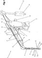
- Fig.1 is a spot welding gun 1 for robot applications for resistance welding of workpieces, in particular sheets, shown in perspective, which for reasons of clarity, only one half of the spot welding gun was shown.
- the spot welding gun 1 consists of a base body 2 and Pliers arms 3, on which electrode holders 4 and electrodes 5 are arranged and around which a circulating belt 6 for protecting the electrodes 5, runs.
- the belt 6 is unrolled by a winding device 7, which may preferably be arranged on the main body 2, but also on the gun arms 3 and along the Zangenarmgeometrie on the gun arm 3, the electrode holder 4 and the electrode 5 and opposite back to the winding device guided.
- the electrode 5 is specially constructed for the use of the belt 6. Of course, it is also possible to use any known from the prior art electrode 5.
- the spacer 5a and the pressure element 5b have a guide for the band 6, so that the band 6 can be distanced from the electrode 5.
- the spacer 5a lifts during or after opening the spot welding gun 1, the tape 6 from the electrode surface or from the electrode cap, whereas during a welding operation, ie with closed spot welding gun 1, the spacer 5a is pushed back, so that the electrode 5 or the electrode cap comes to rest on the belt 6.
- a pressure or a force is exerted by the spacer element 5a on the workpiece or sheet, so that, for example, the process-related bending or buckling of the sheets or components is prevented.
- the use of such an electrode 5 or such an electrode structure ensures that the band 6 does not come into direct contact with the electrode cap when the spot welding gun 1 is open, so that the band 6 can not rub against the electrode 5 during displacement and thus the service life the electrode 5 is substantially increased.
- the band 6 can be brought to the electrode 5, devices, in particular deflection rollers and sliding surfaces 9, are arranged on the forceps arm 3 and / or on the electrode holder 4 for guiding and deflecting the band 6.
- the band 6 extends in this case of a arranged in the winding device 7 take-off roller 10 via guide grooves 8 and a channel, the electrode holder 4 to the electrode 5 and from this in turn via the electrode holder 4 and guide grooves 8 and a channel to a take-up reel 11, which in turn in the Winding device 7 is arranged.
- the take-off reel 10 and / or the take-up reel 11 is coupled to a drive means 12, in particular an electronically controllable motor, so that a targeted displacement of the belt 6 is made possible by actuation of the drive means 12.
- the unwinding roller 10 and take-up reel 11 is designed so that a simple and uncomplicated replacement or replacement of the rollers or the belt 6 can be made.
- the take-off reel 10 and the take-up reel 11 are mounted in the base body 2 or in the tong arm 3 in such a way that they can be easily exchanged, whereby an automatic coupling with the drive means 12 is produced when the take-off reel 10 and / or the take-up reel 11 are used.
- the arrangement of the unwinding rollers 10 and the take-up rollers 11 and the drive means 12 on the base body 2 or on the gun arms 3 ensures that easier access to the coils is ensured, thereby significantly simplifying and facilitating the replacement of the take-off reel 10 and take-up reel 11 becomes.
- the pliers arms 3 are adjustably mounted and by an actuating means 13, which may be formed for example by a servo motor or a cylinder 14, are adjusted.
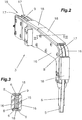
- Fig.2 is a gun arm 3 a spot welding gun 1 perspective and schematically simplified and in Figure 3 a sectional view of the gun arm 3 along the section line III-III in Fig.2 shown.
- the take-off reel 10 and the take-up reel 11 of the winding device 7 are arranged in the main body 2, not shown, to which the tong arm 3 is attached.
- the gun arm 3 of the spot welding gun 1 is formed from a base profile 15 on which side parts 16 are arranged on both sides, which protrude beyond the base profile 15, so that a depression is formed, which serves as a guide groove 8 for the band 6.
- the side parts 16 can be made of aluminum, whereby an enormous weight saving is achieved.
- the side panels 16 may be made of any other material.
- the guide groove 8 is formed such that the surface on which the belt 6 runs along, serves as a sliding surface 9.
- a cover plate 18 is preferably arranged, which covers the formed guide groove 8 between the side parts 16.
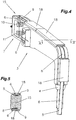
- a further embodiment of a gun arm 3 of a spot welding gun 1 is shown.
- the take-off reel 10 and the take-up reel 11 of the winding device 7 are integrated in the tong arm 3.
- the guide groove 8 is incorporated, which extends from the beginning of the gun arm 3, that is from the position of the take-off reel 10 or take-up reel 11 to the electrode 5.
- the guide groove 8 is preferably formed by milling the base profile 15. It is possible to cover the guide groove 8 again by a cover plate 18. With such a construction, the tong arm 3 consists of only a few parts.
- FIG.6 and 7 Another embodiment is in the Fig.6 and 7 shown.
- the guide groove 8 by additional guide elements 19 formed, which are plugged or screwed on the gun arm 3 and / or on the electrode holder 4.
- the guide elements 19 are thus designed as additional components and are mounted on the base profile 15.
- commercially available spot welding guns 1 can be converted to a belt system without the gun arms 3 and / or the electrode holder 4 having to be exchanged or machined.
- the guide elements 19 may be made of plastic, but also of any other material.
- the winding device 7, the take-off roller 10 and the take-up roll 11 can also be formed as an additional element and subsequently mounted in a simple form on the base body 2 and the gun arm 3 (not shown).
- the tong arm 3 can according to the 8 and 9 may also be formed of a plurality of individual parts 20, which are connected to one another such that in the center of the gun arm 3, a cavity 21 is formed, in which the band 6 extends.
- the items 20 can either be screwed together or put together.
- the gun arm 3 may also be formed by a profile tube, to which incorporated guide grooves 8 may be arranged both on the inner sides of the profile tube and on the outer sides of the profile tube.
- a braking device 22 for the belt 6 is arranged in the region of the unwinding roller 10 and / or the winding roller 11, which is controlled by a control device 23 and keeps the belt 6 taut. This prevents that the band 6 is wedged in the cavity 21 or in the guide groove 8 or hanging loose.
- the braking device 22 can also be used in the previously described embodiments, and is preferably integrated in the winding device 7. On a detailed presentation is omitted, since the training can be done in many different ways. In this case, the braking device 22 could be formed by two mutually movable pressure elements, between which the belt 6 is guided, with activated braking device 22 these pressure elements are moved to the belt 6 and thus the belt 6 is fixed. The task of the braking device 22 lies in the fact that this fixed after advancing the tape 6, so that the band 6 is always tense.
- Figure 10 is a spot welding gun 1 for robot applications for resistance welding of workpieces, in particular sheets, shown in perspective.
- a base body 2 pivotally mounted pliers arms 3 are fixed with electrode holders 4 for receiving the electrodes 5.
- the pliers arms 3 are via an actuating means 13 (see Fig.1 ) adjustable.
- the actuating means 13 may be formed by a servo motor or a cylinder 14 or any other possible actuation.
- a main element 24 is biased by at least one tension strut or traction cable 25.
- the tong arm 3 may for example consist of a main element 24 and at least one retaining plate 26 fastened to the main element 24.
- the main element 24 is preferably designed in the form of a round profile.
- a tension strut or a traction cable 25 is attached and connected to the main element 24.
- the tension strut or pull cable 25 is fastened on that side of the main element 24 on which the electrode receptacle 4 extends.
- a holding strut or a tether 27 is arranged on the opposite side of the tension strut or the traction cable 25 arranged.
- the tong arm 3 is connected via the holding plate 26 with the base body 2, in particular with a receiving element 28.
- the holding plate 26 may be omitted and the main element 24 and the traction cable 25 and optionally the tether 27 is connected directly to the receiving element 28.
- the pull cable 25 and the tether 27 is arranged on one side of the main element 24 from the main element 24 and both the pull cable 25 and the tether 27 with the main element 24 or arranged on the main element 24 fastener (not shown) connected is.
- corresponding tensile and holding forces are built up on the main element 24 of the tong arm 3 via the pull cable 25 and / or the tether 27 can be.
- the tension strut or the pull cable 25 and / or the holding strut or the tether 27 are arranged at an angle, preferably between 10 ° and 30 ° to the main element 24, ie, that they extend at least in a partial region at an angle to the surface of the main element 24 , It is possible that the traction cable 25 and / or the tether 27 are guided over a partial area parallel to the surface of the main element 24, but in the connection area, these run at an angle, as for example in Figure 11 is shown.
- Such a design of the tong arm 3 ensures that the main element 24 can have a very small cross-section, since the pressure forces of the spot welding gun 1 are absorbed by the pull cable 25 and / or the tether 27. Thus, the weight of the spot welding gun 1 can be substantially reduced.
- FIG 11 Another embodiment is shown with such a Zangenarmsystem with ropes or struts.
- the main element 24 of the gun arm 3 extends beyond the base body 2 of the spot welding gun 1, wherein this is movably mounted in the base body 2 and the two base body 2 are mounted to each other movable.
- the gun arm 3 projects on the opposite side, on which the electrode holder 4 is attached, beyond the base body 2 and is movably mounted in the base body 2, so that a lever is formed.
- the projecting beyond the main body 2 part of the gun arm 3 is connected to the actuating element 13.
- the actuator 13 may be formed by a cylinder 14.
- a plurality of holding plates 26 are arranged on the gun arm 3, in particular on the main element 24, over which the pull cable 25 and the holding strut or the tether 27 are guided distanced.
- the traction cable 25 is fixed to the receiving element 28 on the base body 2 and with the gun arm 3, whereas the tether 27 from the end region of the gun arm 3 with the electrode holder 4 extends to the opposite side of the base body 2 and is connected there to the gun arm 3. This is also possible with the pull cable 25.
- the holding plates 26 corresponding openings, which are used simultaneously as a guide groove 8 and channel.
- the take-off reel 10 and take-up reel 11 can be integrated in the main body 2 (see Fig.1 ).
Landscapes
- Engineering & Computer Science (AREA)
- Mechanical Engineering (AREA)
- Robotics (AREA)
- Resistance Welding (AREA)
Description
- Die Erfindung betrifft eine Punktschweißzange für Roboteranwendungen zum Widerstandsschweißen von Werkstücken, insbesondere Blechen, nach dem Oberbegriff des Patentanspruchs 1.
- Die
DE 44 16 504 A1 zeigt eine Punktschweißzange mit einer Wickelvorrichtung zum Auf- und Abwickeln eines Elektrodenschutzbandes ohne im Detail auf den Verlauf des Bandes und die Anordnung der Wickelvorrichtung einzugehen. - Aus der
DE 197 54 546 C1 ist ein Punktschweißwerkzeug mit einer Wickelvorrichtung zum Auf- und Abwickeln von an der Elektrodenspitze der Punktschweißelektrode quer anliegendem Folienband bekannt. Das Punktschweißwerkzeug ist mit einer ringförmigen Abwickelspule zum Abwickeln des Folienbandes und einer ringförmigen Aufwickelspule zum Aufwickeln des Folienbandes ausgestattet und weist eine ringförmige Antriebsvorrichtung zum getakteten Drehen der Aufwickelspule auf. Die Abwickelspule, die Aufwickelspule und die Antriebsvorrichtung sind koaxial zueinander nebeneinander rings des Elektrodenschafts bzw. des Elektrodenhalters der Punktschweißelektrode angeordnet. Schräg zu dem Elektrodenschaft und im radialen Abstand von der Abwickelspule ist eine erste Schränkrolle angeordnet, mittels derer das Folienband von der Abwickelspule zur Elektrodenspitze hin umlenkbar und querstellbar ist. Ferner ist schräg zum Elektrodenschaft und im radialen Abstand von der Aufwickelspule eine zweite Schränkrolle angeordnet, mittels derer das Folienband von der Elektrodenspitze zu der Aufwickelspule hin umlenkbar und querstellbar ist, wobei die beiden Schränkrollen aneinander gegenüberliegend seitens des Elektrodenschafts angeordnet sind. - Eine ähnliche Ausbildung ist auch aus der
JP 05 192 774 - Nachteilig ist bei den zuvor genannten Ausbildungen, dass durch die Anordnung der Auf- und Abwickelspule im Bereich des Elektrodenschafts bzw. des Elektrodenhalters die Zugänglichkeit des Punktschweißwerkzeuges sehr eingeschränkt wird, da eine wesentliche Verbreiterung der Punktschweißzange im Endbereich, insbesondere im Schweißbereich, zustande kommt. Somit können mit einem derartigen Punktschweißwerkzeug nur leicht zugängliche Werkstücke punktgeschweißt werden.
- Andere Konstruktionen von Punktschweißgeräten mit Bändern zum Schutz der Elektroden sind aus der
JP 10 029 071 A JP 08 118 037 A JP 04 322 886 A JP 05 192 774 A - Die
US 5 961 854 A zeigt eine Punktschweißzange mit einer Wickelvorrichtung zum Auf- und Abwickeln eines Elektrodenschutzbandes, wobei keine näheren Angaben über die Anordnung der Wickelvorrichtung und den Verlauf des Elektrodenschutzbandes gegeben sind. Die Punktschweißzange ist relativ voluminös, wodurch die Zugänglichkeit von Werkstücken beeinflusst wird. - Die
US 4 481 401 A zeigt eine Punktschweißzange mit Wickelvorrichtungen zum Auf- und Abwickeln eines Elektrodenschutzbandes, wobei vor der Elektrode ein Ring zur Führung des Elektrodenschutzbandes angeordnet ist. Von diesem Ring zur Wickelvorrichtung verläuft das Band jedoch in einem Winkel zum Zangenarm, wodurch auch relativ viel Platz benötigt wird. - Die
SU 1 206 038 A - Auch die
GB 571 401 A JP 55141387 A - Schließlich zeigt die
DE 199 48 043 A1 eine Roboterschweißzange gemäß der vorliegenden Anmeldung, wobei jedoch keine Wickelvorrichtung zum Auf- und Abwickeln eines Bandes zum Schutz zumindest einer Elektrode geoffenbart ist. - Nachteilig ist hierbei, dass damit ein sehr großer Platzbedarf notwendig ist, so dass eine direkte Anwendung nur bei flachen Werkstücken möglich ist. Somit ist ein Einsatz im automatisierten Bereich, insbesondere bei einem Roboter, nicht möglich.
- Ein weiterer sehr wesentlicher Nachteil liegt bei dem zuvor erwähnten Stand der Technik darin, dass das Band bei der Förderung über die Elektrode gezogen wird und somit aufgrund der Reibung zwischen der Elektrode und dem Band ein hoher Elektrodenverschleiß zustande kommt.
- Die Aufgabe der vorliegenden Erfindung besteht daher in der Schaffung einer Punktschweißzange für Roboteranwendungen zum Widerstandsschweißen von Werkstücken, bei der die Zugänglichkeit nicht wesentlich beeinflusst wird und ein sehr einfacher und kompakter Aufbau der Punktschweißzange mit einem Elektrodenschutzband geschaffen wird. Darüber hinaus soll der Wechsel des Bandes möglichst einfach und rasch möglich sein.
- Die erfindungsgemäße Aufgabe wird dadurch gelöst, dass am Zangenarm und an der Elektrodenaufnahme zumindest eine Führungsnut für die Führung des Bandes entlang des Zangenarmes angeordnet ist, und an jeder Elektrode im Bereich einer Elektrodenkappe ein Distanzhalter und ein Druckelement angeordnet sind, die in Längsrichtung der Elektrode beweglich mit dieser verbunden sind, wobei das Druckelement eine Kraft auf den Distanzhalter ausübt und der Distanzhalter und das Druckelement eine Führung für das Band aufweisen, sodass bei geschlossenen Zangenarmen der Distanzhalter zurückgeschoben wird und die Elektrode am Band zum Anliegen kommt, und während oder nach Öffnen der Zangenarme das Band von der Elektrode distanzierbar ist. Dadurch wird erreicht, dass das Band bei geöffneter Punktschweißzange nicht direkt an der Elektrodenkappe zum Anliegen kommt, sodass das Band beim Verschieben nicht an der Elektrode reiben kann und somit die Lebensdauer der Elektrode wesentlich erhöht wird.
- Gemäß einem weiteren Merkmal der Erfindung ist vorgesehen, dass am Zangenarm und bzw. oder an der Elektrodenaufnahme Vorrichtungen zum Führen und Umlenken des Bandes, insbesondere Umlenkrollen und Gleitflächen, angeordnet sind.
- Die Abspulrolle und bzw. oder die Aufwickelrolle der Wickelvorrichtung ist mit einem Antriebsmittel, insbesondere einem elektronisch ansteuerbaren Motor, gekoppelt.
- Wenn der Zangenarm aus einem Grundprofil gebildet ist und beiderseits des Grundprofils Seitenteile angeordnet sind, die über das Grundprofil hinausragen und die dadurch entstehende Vertiefung als Führungsnut für das Band ausgebildet wird, ist eine einfache Herstellung des Zangenarms verbunden.
- Wenn an den Stirnseiten der Seitenteile zumindest eine Abdeckplatte zur Abdeckung der zwischen den Seitenteilen gebildeten Führungsnut angeordnet ist, kann die Führungsnut vor Fremdkörpern oder etwaiger Verschmutzung geschützt werden.
- Ebenso ist es möglich, dass der Zangenarm aus einem Grundprofil gebildet wird, und dass in dem Grundprofil die Führungsnut eingearbeitet ist. Dabei wird die Führungsnut in das Grundprofil, beispielsweise durch Fräsen, eingearbeitet.
- Ein Nachrüsten bestehender Punktschweißzangen ohne größerem Aufwand ist dadurch möglich, dass die Führungsnut durch zusätzliche Führungselemente gebildet ist, die am Zangenarm und bzw. oder der Elektrodenaufnahme angeordnet, beispielsweise aufgesteckt oder aufgeschraubt, werden.
- Eine besonders einfache Ausführungsvariante ist auch dadurch gegeben, dass der Zangenarm aus mehreren Einzelteilen gebildet wird, welche derart miteinander verbunden werden, dass im Zentrum des Zangenarms ein Hohlraum zur Verfügung des Bandes gebildet wird.
- Gemäß einem weiteren Merkmal der Erfindung ist eine Bremsvorrichtung zum Fixieren und Spannen des Bandes vorgesehen, welche vorteilhafterweise im Bereich der Abspul- oder Aufwickelrolle angeordnet ist und ein Verkanten und Durchhängen des Elektrodenschutzbandes vermeidet.
- Wenn die Bremsvorrichtung mit einer Steuervorrichtung verbunden ist, kann eine entsprechende Steuerung der Bremsvorrichtung erfolgen.
- Die vorliegende Erfindung wird anhand der beigefügten Zeichnungen näher erläutert.
- Darin zeigen:
-
Fig.1 eine perspektivische Ansicht einer erfindungsmäßigen Punktschweißzange; -
Fig.2 eine perspektivische Ansicht eines Zangenarms der erfindungsgemäßen Punktschweißzange; -
Fig.3 eine Schnittdarstellung des Zangenarms entlang der Schnittlinie III-III inFig.2 ; -
Fig.4 eine weitere perspektivische Ansicht des Zangenarms entlang der gemäßen Punktschweißzange; -
Fig.5 wiederum eine Schnittdarstellung des inFig.4 dargestellten Zangenarms entlang der inFig.4 dargestellten Schnittlinie V-V; -
Fig.6 eine weitere perspektivische Ansicht eines Zangenarms der erfindungsgemäßen Punktschweißzange; -
Fig.7 eine Schnittdarstellung eines Zangenarms entlang der Schnittlinie VII-VII inFig.6 ; -
Fig.8 eine weitere perspektivische Ansicht eines Zangenarms der erfindungsgemäßen Punktschweißzange; -
Fig.9 wiederum eine Schnittdarstellung entlang der Schnittlinie IX-IX gemäßFig.8 ; -
Fig.10 und11 perspektivische Ansichten erfindungsmäßiger Punktschweißzangen. - In
Fig.1 ist eine Punktschweißzange 1 für Roboteranwendungen zum Widerstandsschweißen von Werkstücken, insbesondere Blechen, perspektivisch dargestellt, wobei übersichtshalber nur eine Hälfte der Punktschweißzange dargestellt wurde. - Die Punktschweißzange 1 besteht aus einem Grundkörper 2 und Zangenarmen 3, an welchen Elektrodenaufnahmen 4 und Elektroden 5 angeordnet sind und um welche ein umlaufendes Band 6 zum Schutz der Elektroden 5, läuft. Das Band 6 wird von einer Wickelvorrichtung 7, welche vorzugsweise an dem Grundkörper 2, aber auch an den Zangenarmen 3 angeordnet sein kann, abgerollt und entlang der Zangenarmgeometrie über den Zangenarm 3, die Elektrodenaufnahme 4 und die Elektrode 5 und gegenüberseitig wieder zurück zur Wickelvorrichtung 7 geführt.
- Die Elektrode 5 ist speziell für den Einsatz des Bandes 6 aufgebaut. Selbstverständlich ist es aber auch möglich, jede beliebige aus dem Stand der Technik bekannte Elektrode 5 einzusetzen. An der Elektrode 5, die im Inneren des Aufbaus angeordnet ist, ist im Bereich einer Elektrodenkappe ein Distanzhalter 5a und ein Druckelement 5b angeordnet, die in Längsrichtung der Elektrode 5 beweglich mit dieser verbunden sind, wobei das Druckelement 5b eine Kraft auf den Distanzhalter 5a ausübt. Der Distanzhalter 5a und das Druckelement 5b weisen eine Führung für das Band 6 auf, so dass das Band 6 von der Elektrode 5 distanzierbar ist. Der Distanzhalter 5a hebt während oder nach dem Öffnen der Punktschweißzange 1 das Band 6 von der Elektrodenoberfläche bzw. von der Elektrodenkappe ab, wogegen während eines Schweißvorganges, also bei geschlossener Punktschweißzange 1, der Distanzhalter 5a zurück geschoben wird, so dass die Elektrode 5 bzw. die Elektrodenkappe am Band 6 zum Anliegen kommt. Dabei wird zusätzlich aufgrund des Druckelements 5b ein Druck bzw. eine Kraft vom Distanzelement 5a auf das Werkstück bzw. Blech ausgeübt, so dass beispielsweise das prozessbedingte Aufbiegen bzw. Wölben der Bleche bzw. Bauteile verhindert wird. Durch den Einsatz einer derartigen Elektrode 5 bzw. eines derartigen Elektrodenaufbaus wird erreicht, dass das Band 6 bei geöffneter Punktschweißzange 1 nicht direkt an der Elektrodenkappe zum Anliegen kommt, so dass das Band 6 beim Verschieben nicht an der Elektrode 5 reiben kann und somit die Lebensdauer der Elektrode 5 wesentlich erhöht wird.
- Damit nunmehr das Band 6 an die Elektrode 5 herangeführt werden kann, sind am Zangenarm 3 und/oder an der Elektrodenaufnahme 4 Vorrichtungen, insbesondere Umlenkrollen und Gleitflächen 9, zum Führen und Umlenken des Bandes 6 angeordnet. Das Band 6 erstreckt sich dabei von einer in der Wickelvorrichtung 7 angeordneten Abspulrolle 10 über Führungsnuten 8 bzw. einem Kanal, der Elektrodenaufnahme 4 zur Elektrode 5 und von dieser wiederum über die Elektrodenaufnahme 4 und über Führungsnuten 8 bzw. einem Kanal zu einer Aufwickelrolle 11, welche wiederum in der Wickelvorrichtung 7 angeordnet ist. Die Abspulrolle 10 und/oder die Aufwickelrolle 11 ist mit einem Antriebsmittel 12, insbesondere einem elektronisch ansteuerbarem Motor, gekoppelt, so dass durch Ansteuerung des Antriebsmittels 12 eine gezielte Verschiebung des Bandes 6 ermöglicht wird.
- Die Abspulrolle 10 und Aufwickelrolle 11 ist so konzipiert, dass ein einfacher und unkomplizierter Wechsel bzw. Austausch der Rollen bzw. des Bandes 6 vorgenommen werden kann. Dabei sind die Abspulrolle 10 und die Aufwickelrolle 11 derart im Grundkörper 2 oder im Zangenarm 3 gelagert, dass diese einfach ausgetauscht werden können, wobei beim Einsatz der Abspulrolle 10 und/oder der Aufwickelrolle 11 eine automatische Koppelung mit dem Antriebsmittel 12 hergestellt wird. Durch die Anordnung der Abspulrollen 10 und der Aufwickelrollen 11 sowie des Antriebsmittels 12 am Grundkörper 2 oder aber auch an den Zangenarmen 3 wird erreicht, dass ein leichterer Zugang zu den Spulen gewährleistet ist und dadurch das Auswechseln der Abspulrolle 10 und Aufwickelrolle 11 wesentlich vereinfacht und erleichtert wird. Ein weiterer positiver Effekt dieser Anordnung der Abspulrolle 10 und Aufwickelrolle 11 besteht darin, dass durch die Führung des Bandes 6 von hinten, also von dem Grundkörper 2 zu der Elektrode 5, keine störenden Elemente bzw. Teile vorhanden sind, was zur Folge hat, dass auch bei komplizierten zugänglichen Werkstücken nahezu problemlos eine Punktschweißung durchgeführt werden kann, da keinerlei Einschränkung der Zugänglichkeit gegenüber Schweißzangen ohne Band 6 gegeben ist. Durch diese Ausgestaltung wird auch erreicht, dass die Baugröße der Punktschweißzange 1 gering gehalten werden kann.
- Der Vollständigkeit halber wird erwähnt, dass die Zangenarme 3 verstellbar gelagert sind und durch ein Betätigungsmittel 13, welches zum Beispiel durch einen Servomotor oder einen Zylinder 14 gebildet sein kann, verstellt werden.
- In
Fig.2 ist ein Zangenarm 3 einer Punktschweißzange 1 perspektivisch und schematisch vereinfacht und inFig.3 eine Schnittdarstellung des Zangenarms 3 entlang der Schnittlinie III-III inFig.2 dargestellt. Die Abspulrolle 10 und die Aufwickelrolle 11 der Wickelvorrichtung 7 sind dabei im nicht dargestellten Grundkörper 2, an dem der Zangenarm 3 befestigt ist, angeordnet. - In dieser Ausführung ist der Zangenarm 3 der Punktschweißzange 1 aus einem Grundprofil 15 gebildet, an welchem beiderseits Seitenteile 16 angeordnet sind, welche über das Grundprofil 15 hinausragen, so dass eine Vertiefung gebildet wird, welche als Führungsnut 8 für das Band 6 dient. Die Seitenteile 16 können aus Aluminium gefertigt werden, wodurch eine enorme Gewichtsersparnis erreicht wird. Natürlich können die Seitenteile 16 aus jedem möglichen anderen Material gefertigt sein. Die Führungsnut 8 ist derart ausgebildet, dass die Fläche, an welcher das Band 6 entlang läuft, als Gleitfläche 9 dient.
- An den Stirnseiten 17 der Seitenteile 16 ist bevorzugt eine Abdeckplatte 18 angeordnet, welche die ausgebildete Führungsnut 8 zwischen den Seitenteilen 16 abdeckt. Dadurch wird das Band 6 nicht nur besser geführt, sondern das Band 6 und die Führungsnut 8 sowie die Gleitfläche 9 werden des Weiteren auch noch vor Verschmutzungen jeglicher Art geschützt, da das Band 6 erst ab dem Bereich der Elektrode 5 im "Freien" verläuft.
- In
Fig.4 und 5 ist eine weitere Ausführungsform eines Zangenarms 3 einer Punktschweißzange 1 dargestellt. Die Abspulrolle 10 und die Aufwickelrolle 11 der Wickelvorrichtung 7 sind dabei im Zangenarm 3 integriert. Weiters ist in dem Grundprofil 15 des Zangenarms 3 die Führungsnut 8 eingearbeitet, die sich vom Anfang des Zangenarms 3, also von der Position der Abspulrolle 10 oder Aufwickelrolle 11 bis zur Elektrode 5 erstreckt. Die Führungsnut 8 wird dabei bevorzugt durch Fräsen des Grundprofils 15 gebildet. Dabei ist es möglich, die Führungsnut 8 wieder durch eine Abdeckplatte 18 abzudecken. Bei einer derartigen Konstruktion besteht der Zangenarm 3 nur aus wenigen Teilen. - Ein weiteres Ausführungsbeispiel ist in den
Fig.6 und 7 gezeigt. Dabei ist die Führungsnut 8 durch zusätzliche Führungselemente 19 gebildet, welche auf dem Zangenarm 3 und/oder auf der Elektrodenaufnahme 4 aufgesteckt oder aufgeschraubt sind. Die Führungselemente 19 sind also als Zusatzbauteile ausgeführt und werden auf dem Grundprofil 15 befestigt. Dadurch können handelsübliche Punktschweißzangen 1 auf ein Bandsystem umgerüstet werden, ohne dass die Zangenarme 3 und/oder die Elektrodenaufnahme 4 getauscht bzw. bearbeitet werden müssen. Die Führungselemente 19 können aus Kunststoff, aber auch aus jedem anderen Material gefertigt sein. - Die Wickelvorrichtung 7, die Abspulrolle 10 und die Aufwickelrolle 11 können ebenfalls als Zusatzelement ausgebildet werden und nachträglich in einfacher Form am Grundkörper 2 bzw. am Zangenarm 3 montiert werden (nicht dargestellt).
- Der Zangenarm 3 kann entsprechend den
Fig.8 und 9 auch aus mehreren Einzelteilen 20 gebildet sein, die derart miteinander verbunden werden, dass im Zentrum des Zangenarms 3 ein Hohlraum 21 gebildet wird, in welchem das Band 6 verläuft. Die Einzelteile 20 können entweder zusammengeschraubt oder auch zusammengesteckt sein. Natürlich kann der Zangenarm 3 auch durch ein Profilrohr gebildet sein, an welchem eingearbeitete Führungsnuten 8 sowohl an den Innenseiten des Profilrohres als auch an den Außenseiten des Profilrohres angeordnet sein können. - Bevorzugt ist im Bereich der Abspulrolle 10 und/oder der Aufwickelrolle 11 eine Bremsvorrichtung 22 für das Band 6 angeordnet, welche von einer Steuervorrichtung 23 angesteuert wird und das Band 6 gespannt hält. Damit wird verhindert, dass das Band 6 sich in dem Hohlraum 21 oder in der Führungsnut 8 verkeilt bzw. lose herumhängt. Die Bremsvorrichtung 22 kann dabei ebenfalls bei den zuvor beschriebenen Ausführungsformen verwendet werden, und ist bevorzugt in der Wickelvorrichtung 7 integriert. Auf eine detaillierte Darstellung wird dabei verzichtet, da die Ausbildung auf die unterschiedlichste Weise erfolgen kann. Dabei könnte die Bremsvorrichtung 22 durch zwei zueinander bewegbare Druckelemente gebildet werden, zwischen denen das Band 6 geführt wird, wobei bei aktivierter Bremsvorrichtung 22 diese Druckelemente auf das Band 6 gefahren werden und somit das Band 6 fixiert wird. Die Aufgabe der Bremsvorrichtung 22 liegt also darin, dass diese nach dem Weiterbewegen des Bandes 6 dieses fixiert, so dass das Band 6 immer gespannt ist.
- In
Fig.10 ist eine Punktschweißzange 1 für Roboteranwendungen zum Widerstandsschweißen von Werkstücken, insbesondere Blechen, perspektivisch dargestellt. An einem Grundkörper 2 sind wiederum schwenkbar gelagerte Zangenarme 3 mit Elektrodenaufnahmen 4 zur Aufnahme der Elektroden 5 befestigt. Die Zangenarme 3 sind über ein Betätigungsmittel 13 (sieheFig.1 ) verstellbar. Das Betätigungsmittel 13 kann dabei durch einen Servomotor oder einen Zylinder 14 oder auch jede andere mögliche Betätigungsart gebildet sein. - Bei dieser Punktschweißzange 1 ist ein Hauptelement 24 durch zumindest eine Zugstrebe oder ein Zugseil 25 vorgespannt. Der Zangenarm 3 kann beispielsweise aus einem Hauptelement 24 und zumindest einer am Hauptelement 24 befestigten Halteplatte 26 bestehen. Das Hauptelement 24 ist bevorzugt in Form eines Rundprofils ausgebildet. An einem oder mehreren Punkten der Halteplatte 26 ist eine Zugstrebe oder ein Zugseil 25 befestigt und mit dem Hauptelement 24 verbunden. Die Zugstrebe oder das Zugseil 25 ist auf jener Seite des Hauptelements 24 befestigt, auf welcher sich die Elektrodenaufnahme 4 erstreckt. Weiters ist es möglich, dass auf der gegenüberliegenden Seite der Zugstrebe oder des Zugseils 25 eine Haltestrebe bzw. ein Halteseil 27 angeordnet ist.
- Der Zangenarm 3 wird über die Halteplatte 26 mit dem Grundkörper 2, insbesondere mit einem Aufnahmeelement 28, verbunden. Selbstverständlich ist es möglich, dass die Halteplatte 26 entfallen kann und das Hauptelement 24 sowie das Zugseil 25 und gegebenenfalls das Halteseil 27 direkt mit dem Aufnahmeelement 28 verbunden wird. Wesentlich ist dabei, dass das Zugseil 25 bzw. das Halteseil 27 auf einer Seite des Hauptelements 24 vom Hauptelement 24 distanziert angeordnet ist und sowohl das Zugseil 25 als auch das Halteseil 27 mit dem Hauptelement 24 oder einem am Hauptelement 24 angeordneten Befestigungselement (nicht dargestellt) verbunden ist. Somit wird nämlich erreicht, dass über das Zugseil 25 und/oder das Halteseil 27 entsprechende Zug- und Haltekräfte auf das Hauptelement 24 des Zangenarms 3 aufgebaut werden können. Hierzu sind die Zugstrebe bzw. das Zugseil 25 und/oder die Haltestrebe bzw. das Halteseil 27 in einem Winkel, bevorzugt zwischen 10° und 30° zum Hauptelement 24 angeordnet, d.h., dass diese zumindest in einem Teilbereich winkelig zur Oberfläche des Hauptelements 24 verlaufen. Es ist nämlich möglich, dass das Zugseil 25 und/oder das Halteseil 27 über einen Teilbereich parallel zur Oberfläche des Hauptelements 24 geführt werden, wobei jedoch im Verbindungsbereich diese winkelig verlaufen, wie dies beispielsweise in
Fig.11 dargestellt ist. - Durch eine derartige Ausbildung des Zangenarms 3 wird erreicht, dass das Hauptelement 24 einen sehr geringen Querschnitt aufweisen kann, da die Druckkräfte der Punktschweißzange 1 über das Zugseil 25 und/oder das Halteseil 27 aufgenommen werden. Somit kann das Gewicht der Punktschweißzange 1 wesentlich verringert werden.
- In
Fig.11 ist ein weiteres Ausführungsbeispiel mit einem derartigen Zangenarmsystem mit Seilen bzw. Streben gezeigt. Dabei erstreckt sich nunmehr das Hauptelement 24 des Zangenarms 3 über den Grundkörper 2 der Punktschweißzange 1 hinaus, wobei dieser im Grundkörper 2 beweglich gelagert ist bzw. die beiden Grundkörper 2 zueinander beweglich gelagert sind. Der Zangenarm 3 ragt an der gegenüberliegenden Seite, an dem der Elektrodenhalter 4 befestigt ist, über den Grundkörper 2 hinaus und ist im Grundkörper 2 beweglich gelagert, so dass ein Hebel gebildet wird. Der über den Grundkörper 2 hinausragende Teil des Zangenarms 3 ist mit dem Betätigungselement 13 verbunden. Das Betätigungselement 13 kann durch einen Zylinder 14 gebildet werden. Durch ein Verstellen des Zylinders 14 wird der Zangenarm 3 derart verstellt, dass die beiden Elektroden 5 aneinander gepresst werden bzw. voneinander wegbewegt werden. - Bei dem in
Fig.11 gezeigten Ausführungsbeispiel sind am Zangenarm 3, insbesondere am Hauptelement 24 mehrere Halteplatten 26 angeordnet, über die das Zugseil 25 und die Haltestrebe bzw. das Halteseil 27 distanziert geführt sind. Das Zugseil 25 ist mit dem Aufnahmeelement 28 am Grundkörper 2 und mit dem Zangenarm 3 befestigt, wogegen das Halteseil 27 vom Endbereich des Zangenarms 3 mit der Elektrodenaufnahme 4 sich auf die gegenüberliegende Seite des Grundkörpers 2 erstreckt und dort mit dem Zangenarm 3 verbunden ist. Dies ist auch bei dem Zugseil 25 möglich. - Bei derartigen Punktschweißzangen 1 ist es wesentlich, dass über das Zugseil 25 und über das Halteseil 27 die Kräfte beim Zusammenpressen der Punktschweißzange 1 aufgenommen werden, so dass das Hauptelement 24 wesentlich kleiner dimensioniert werden kann. Somit wird in einfacher Art und Weise eine sehr wesentliche Gewichtseinsparung erzielt.
- Für den Einsatz des Bandes 6 zum Schutz der Elektroden weisen die Halteplatten 26 entsprechende Öffnungen auf, die gleichzeitig als Führungsnut 8 bzw. Kanal verwendet werden. Die Abspulrolle 10 und Aufwickelrolle 11 können im Grundkörper 2 integriert werden (siehe
Fig.1 ).
Claims (10)
- Punktschweißzange (1) für Roboteranwendungen zum Widerstandsschweißen von Werkstücken, insbesondere Blechen, mit an einem Grundkörper (2) schwenkbar gelagerten Zangenarmen (3), welche über ein Betätigungsmittel (13) verstellbar sind, und an welchen Elektrodenaufnahmen (4) für die Elektroden (5) befestigt sind, und mit einer eine Abspulrolle (10) und eine Aufwickelrolle (11) umfassenden Wickelvorrichtung (7) zum Auf- und Abwickeln eines Bandes (6) zum Schutz zumindest einer Elektrode (5), wobei die Abspulrolle (10) und die Aufwickelrolle (11) der Wickelvorrichtung (7) am Grundkörper (2) oder am Zangenarm (3) angeordnet ist, dadurch gekennzeichnet, dass am Zangenarm (3) und an der Elektrodenaufnahme (4) zumindest eine Führungsnut (8) für die Führung des Bandes (6) entlang des Zangenarmes (3) angeordnet ist, und an jeder Elektrode (5) im Bereich einer Elektrodenkappe ein Distanzhalter (5a) und ein Druckelement (5b) angeordnet sind, die in Längsrichtung der Elektrode (5) beweglich mit dieser verbunden sind, wobei das Druckelement (5b) eine Kraft auf den Distanzhalter (5a) ausübt und der Distanzhalter (5a) und das Druckelement (5b) eine Führung für das Band (6) aufweisen, sodass bei geschlossenen Zangenarmen (3) der Distanzhalter (5a) zurückgeschoben wird und die Elektrode (5) am Band (6) zum Anliegen kommt, und während oder nach dem Öffnen der Zangenarme (3) das Band (6) von der Elektrode (5) distanzierbar ist.
- Punktschweißzange nach Anspruch 1, dadurch gekennzeichnet, dass am Zangenarm (3) und bzw. oder an der Elektrodenaufnahme (4) Vorrichtungen zum Führen und Umlenken des Bandes (6), insbesondere Umlenkrollen und Gleitflächen (9), angeordnet sind.
- Punktschweißzange nach Anspruch 1 oder 2, dadurch gekennzeichnet, dass die Abspulrolle (10) und bzw. oder die Aufwickelrolle (11) mit einem Antriebsmittel (12), insbesondere einem elektronisch ansteuerbaren Motor, gekoppelt ist.
- Punktschweißzange nach einem oder mehreren der Ansprüche 1 bis 3, dadurch gekennzeichnet, dass der Zangenarm (3) aus einem Grundprofil (15) gebildet ist, und dass beiderseits des Grundprofils (15) Seitenteile (16) angeordnet sind, die über das Grundprofil (15) hinausragen und die dadurch entstehende Vertiefung als Führungsnut (8) für das Band (6) ausgebildet ist.
- Punktschweißzange nach Anspruch 4, dadurch gekennzeichnet, dass an den Stirnseiten (17) der Seitenteile (16) zumindest eine Abdeckplatte (18) zur Abdeckung der zwischen den Seitenteilen (16) gebildeten Führungsnut (8) angeordnet ist.
- Punktschweißzange nach einem oder mehreren der Ansprüche 1 bis 3, dadurch gekennzeichnet, dass der Zangenarm (3) aus einem Grundprofil (15) gebildet ist, und dass in dem Grundprofil (15) die Führungsnut (8) eingearbeitet ist.
- Punktschweißzange nach einem oder mehreren der Ansprüche 1 bis 3, dadurch gekennzeichnet, dass die Führungsnut (8) durch zusätzliche Führungselemente (19) gebildet ist, die am Zangenarm (3) und bzw. oder der Elektrodenaufnahme (4) angeordnet, beispielsweise aufgesteckt oder aufgeschraubt, sind.
- Punktschweißzange nach einem oder mehreren der Ansprüche 1 bis 3, dadurch gekennzeichnet, dass der Zangenarm (3) aus mehreren Einzelteilen (29) gebildet ist, welche derart miteinander verbunden sind, dass im Zentrum des Zangenarms (3) ein Hohlraum (21) zur Führung des Bandes (6) ausgebildet ist.
- Punktschweißzange nach einem oder mehreren der Ansprüche 1 bis 8, dadurch gekennzeichnet, dass eine Bremsvorrichtung (22) zum Fixieren und Spannen des Bandes (6) vorgesehen ist.
- Punktschweißzange nach Anspruch 9, dadurch gekennzeichnet, dass die Bremsvorrichtung (22) mit einer Steuervorrichtung (23) verbunden ist.
Priority Applications (1)
| Application Number | Priority Date | Filing Date | Title |
|---|---|---|---|
| EP12159470.9A EP2465633B1 (de) | 2003-07-03 | 2004-05-04 | Punktschweißzange für Roboteranwendungen zum Widerstandsschweißen von Werkstücken |
Applications Claiming Priority (2)
| Application Number | Priority Date | Filing Date | Title |
|---|---|---|---|
| AT0102303A AT413664B (de) | 2003-07-03 | 2003-07-03 | Punktschweisszange für roboteranwendungen zum widerstandsschweissen von werkstücken |
| PCT/AT2004/000151 WO2005002776A1 (de) | 2003-07-03 | 2004-05-04 | Punktschweisszange für roboteranwendungen zum widerstandsschweissen von werkstücken |
Related Child Applications (2)
| Application Number | Title | Priority Date | Filing Date |
|---|---|---|---|
| EP12159470.9A Division EP2465633B1 (de) | 2003-07-03 | 2004-05-04 | Punktschweißzange für Roboteranwendungen zum Widerstandsschweißen von Werkstücken |
| EP12159470.9A Division-Into EP2465633B1 (de) | 2003-07-03 | 2004-05-04 | Punktschweißzange für Roboteranwendungen zum Widerstandsschweißen von Werkstücken |
Publications (2)
| Publication Number | Publication Date |
|---|---|
| EP1663563A1 EP1663563A1 (de) | 2006-06-07 |
| EP1663563B1 true EP1663563B1 (de) | 2016-12-14 |
Family
ID=33556908
Family Applications (2)
| Application Number | Title | Priority Date | Filing Date |
|---|---|---|---|
| EP12159470.9A Expired - Lifetime EP2465633B1 (de) | 2003-07-03 | 2004-05-04 | Punktschweißzange für Roboteranwendungen zum Widerstandsschweißen von Werkstücken |
| EP04730943.0A Expired - Lifetime EP1663563B1 (de) | 2003-07-03 | 2004-05-04 | Punktschweisszange für roboteranwendungen zum widerstandsschweissen von werkstücken |
Family Applications Before (1)
| Application Number | Title | Priority Date | Filing Date |
|---|---|---|---|
| EP12159470.9A Expired - Lifetime EP2465633B1 (de) | 2003-07-03 | 2004-05-04 | Punktschweißzange für Roboteranwendungen zum Widerstandsschweißen von Werkstücken |
Country Status (7)
| Country | Link |
|---|---|
| US (2) | US8178817B2 (de) |
| EP (2) | EP2465633B1 (de) |
| JP (1) | JP4567677B2 (de) |
| CN (1) | CN1816411B (de) |
| AT (1) | AT413664B (de) |
| BR (1) | BRPI0412178A (de) |
| WO (1) | WO2005002776A1 (de) |
Families Citing this family (7)
| Publication number | Priority date | Publication date | Assignee | Title |
|---|---|---|---|---|
| AT503310B1 (de) * | 2006-02-17 | 2008-07-15 | Fronius Int Gmbh | Punktschweisselektrode und punktschweisszange mit einer solchen elektrode |
| AT504925B1 (de) | 2007-02-23 | 2009-01-15 | Fronius Int Gmbh | Punktschweisselektrode und punktschweissverfahren |
| KR101209729B1 (ko) * | 2010-09-16 | 2012-12-07 | 현대자동차주식회사 | 편 방향 스폿 용접장치 |
| DE102011002620A1 (de) * | 2011-01-13 | 2012-07-19 | Ford Global Technologies, Llc | Schweißverfahren |
| CN107671409A (zh) * | 2017-09-27 | 2018-02-09 | 北京中戎华泰科技开发有限公司 | 一种应用于电阻焊电极帽检测的视觉检测装置的使用方法 |
| KR102128759B1 (ko) * | 2018-12-14 | 2020-07-01 | 주식회사 성우하이텍 | 스폿 용접 장치 |
| CN118268452B (zh) * | 2024-06-03 | 2024-08-30 | 四川明泰微电子科技股份有限公司 | 一种翻转式切筋模具及切筋装置 |
Family Cites Families (38)
| Publication number | Priority date | Publication date | Assignee | Title |
|---|---|---|---|---|
| US2093394A (en) * | 1931-07-13 | 1937-09-14 | Charles F Perner | Method and apparatus for forming and feeding welding material |
| GB571401A (en) * | 1944-01-19 | 1945-08-23 | English Electric Co Ltd | An electrode arrangement suitable for resistance welding |
| US2678367A (en) | 1949-08-27 | 1954-05-11 | M & S Maschinen Und Stahl A G | Electric resistance welding machine for spot or seam welding |
| US2749421A (en) * | 1954-06-17 | 1956-06-05 | Worthington Corp | Welding head positioner |
| FR1444269A (fr) * | 1965-05-21 | 1966-07-01 | Nord Aviation | Machine à souder par résistance |
| US3396860A (en) * | 1966-04-12 | 1968-08-13 | Hein Werner Corp | Excaator and grader or crane apparatus |
| US4037073A (en) * | 1967-02-11 | 1977-07-19 | Otto Alfred Becker | Resistance welding of sheet metal coated with layers |
| US4024370A (en) * | 1975-09-08 | 1977-05-17 | Sciaky Bros., Inc. | Toroidal resistance welding transformer |
| BR7800978A (pt) * | 1977-02-18 | 1978-09-19 | Elfin Spa | Maquina de soldar a resistencia |
| US4267424A (en) * | 1978-05-22 | 1981-05-12 | Nissan Motor Company, Limited | Spot welding machine for heavy-duty operations on surface contoured workpieces |
| JPS55141387A (en) * | 1979-04-23 | 1980-11-05 | Hitachi Ltd | Spot welding method |
| US4278863A (en) * | 1979-08-20 | 1981-07-14 | Harnischfeger Corporation | Method of making welded structure |
| US4481401A (en) * | 1981-09-24 | 1984-11-06 | Steelweld France | Process for welding coated plates |
| US4545519A (en) * | 1983-04-12 | 1985-10-08 | Fairchild Industries, Inc. | Method and apparatus for preventing tip sticking during welding operation |
| US4525618A (en) * | 1983-10-26 | 1985-06-25 | Beneteau Donald J | Resistance welding apparatus |
| SU1206038A1 (ru) * | 1984-01-27 | 1986-01-23 | Предприятие П/Я А-1264 | Устройство дл контактной точечной сварки |
| US4684778A (en) | 1984-04-30 | 1987-08-04 | Cecil Dimitrios G | Resistance spot welding gun and transformer assembly |
| GB2175834B (en) * | 1985-05-29 | 1988-10-05 | Honda Motor Co Ltd | Workpiece feeding apparatus in a seam welding machine |
| CA1310706C (en) * | 1988-04-26 | 1992-11-24 | Toshihiko Okada | Water cooled plasma arc apparatus |
| CA1321627C (en) * | 1988-06-22 | 1993-08-24 | Naoteru Katsura | Method and apparatus for supplying electric power to resistance welding gun |
| US4947017A (en) | 1989-04-03 | 1990-08-07 | General Motors Corporation | Composite weld gun and method of making same |
| JPH04322886A (ja) * | 1991-04-24 | 1992-11-12 | Furukawa Alum Co Ltd | 金属板の抵抗溶接装置 |
| JP2867777B2 (ja) | 1992-01-17 | 1999-03-10 | トヨタ自動車株式会社 | 抵抗スポット溶接用電極保護装置 |
| US5252801A (en) * | 1992-06-12 | 1993-10-12 | Progressive Tool & Industries Co. | Fixed point welding gun |
| DE4416504C2 (de) * | 1994-05-10 | 2002-07-18 | Bayerische Motoren Werke Ag | Elektrode zum Widerstands-Punktschweißen |
| IT1268100B1 (it) * | 1994-10-07 | 1997-02-20 | Stola Spa | Dispositivo per la saldatura di scocche di autoveicolo o di loro sotto-gruppi. |
| JPH08118037A (ja) | 1994-10-28 | 1996-05-14 | Furukawa Electric Co Ltd:The | 金属板の抵抗溶接方法及び抵抗溶接装置 |
| DE19539194A1 (de) * | 1995-10-20 | 1997-04-24 | Schlattl Werner Bavaria Tech | Verfahren zum Steuern einer Schweißeinrichtung sowie Schweißeinrichtung |
| JPH1029071A (ja) | 1996-07-12 | 1998-02-03 | Furukawa Electric Co Ltd:The | 電気抵抗スポット溶接用自動インサート供給装置 |
| CN1044451C (zh) * | 1996-08-20 | 1999-08-04 | 李崇蓉 | 带变压器一体化悬挂式点焊机 |
| DE19637410C1 (de) * | 1996-09-13 | 1998-01-02 | Bayerische Motoren Werke Ag | Elektrode zum Widerstands-Punktschweißen von Aluminium-Blechen |
| DE19754546A1 (de) | 1997-12-09 | 1999-06-10 | Bayerische Motoren Werke Ag | Punktschweißwerkzeug mit einer Wickelvorrichtung |
| US20020005397A1 (en) * | 1998-04-10 | 2002-01-17 | Bong William L. | Modular welding system and method |
| DE19819721A1 (de) * | 1998-05-02 | 1999-11-04 | Ortwin Hahn | Vorrichtung zum mechanischen Fügen von aufeinanderliegenden Fügeteilen |
| JP3761344B2 (ja) * | 1998-12-01 | 2006-03-29 | トヨタ自動車株式会社 | 溶接ガンとそれを用いたセンサー校正方法、溶接制御方法、溶接打点位置精度変化管理方法 |
| DE19948043A1 (de) * | 1999-10-06 | 2001-04-12 | Nimak Automatisierte Schweiste | Roboterschweißzange |
| AT413665B (de) * | 2002-09-06 | 2006-04-15 | Fronius Int Gmbh | Verfahren zur qualitätsüberwachung von punktschweissungen |
| KR100551796B1 (ko) * | 2003-07-15 | 2006-02-13 | 기아자동차주식회사 | 자동차의 점 용접에 사용되는 리일 와이어 방식 용접 장치 |
-
2003
- 2003-07-03 AT AT0102303A patent/AT413664B/de not_active IP Right Cessation
-
2004
- 2004-05-04 EP EP12159470.9A patent/EP2465633B1/de not_active Expired - Lifetime
- 2004-05-04 BR BRPI0412178-3A patent/BRPI0412178A/pt not_active IP Right Cessation
- 2004-05-04 JP JP2006515531A patent/JP4567677B2/ja not_active Expired - Fee Related
- 2004-05-04 EP EP04730943.0A patent/EP1663563B1/de not_active Expired - Lifetime
- 2004-05-04 US US10/563,528 patent/US8178817B2/en not_active Expired - Fee Related
- 2004-05-04 WO PCT/AT2004/000151 patent/WO2005002776A1/de not_active Ceased
- 2004-05-04 CN CN200480018538.XA patent/CN1816411B/zh not_active Expired - Fee Related
-
2009
- 2009-07-09 US US12/499,798 patent/US20090266797A1/en not_active Abandoned
Non-Patent Citations (1)
| Title |
|---|
| None * |
Also Published As
| Publication number | Publication date |
|---|---|
| US20060163212A1 (en) | 2006-07-27 |
| US20090266797A1 (en) | 2009-10-29 |
| CN1816411B (zh) | 2011-10-19 |
| EP2465633B1 (de) | 2016-10-19 |
| CN1816411A (zh) | 2006-08-09 |
| ATA10232003A (de) | 2005-09-15 |
| JP2007537873A (ja) | 2007-12-27 |
| US8178817B2 (en) | 2012-05-15 |
| EP2465633A1 (de) | 2012-06-20 |
| JP4567677B2 (ja) | 2010-10-20 |
| EP1663563A1 (de) | 2006-06-07 |
| BRPI0412178A (pt) | 2006-08-22 |
| WO2005002776A1 (de) | 2005-01-13 |
| AT413664B (de) | 2006-04-15 |
Similar Documents
| Publication | Publication Date | Title |
|---|---|---|
| DE102006006715B4 (de) | Vorrichtung und Verfahren zum Ausrichten und Befestigen eines Bandes an einer Solarzelle | |
| DE102011051170A1 (de) | Werkstückauflage für eine Bearbeitungsmaschine sowie Bearbeitungsmaschine | |
| DE2933704A1 (de) | Druckmittelverbindung zwischen einem ventilblock und einem zumindest einen doppelt wirkenden druckmittelmotor aufweisenden verbraucher | |
| WO2021179028A1 (de) | Biegemaschine | |
| DE10025467A1 (de) | Parallel greifendes Spannfutter | |
| DE10223821A1 (de) | Schweisszange | |
| EP1802418B1 (de) | Punktschweisszange und verfahren zum einstellen des druckes einer punktschweisszange | |
| AT413664B (de) | Punktschweisszange für roboteranwendungen zum widerstandsschweissen von werkstücken | |
| DE102007044974A1 (de) | Vorrichtung zum manuellen Fügen oder manuellen Bearbeiten von Werkstücken | |
| EP1689551B1 (de) | PUNKTSCHWEIßZANGE ZUM WIDERSTANDSSCHWEIßEN VON WERKSTÜCKEN | |
| DE1514285B2 (de) | Verfahren zur Herstellung einer Halbleitervorrichtung | |
| DE4334681A1 (de) | Bewegungseinheit zur Erzeugung einer Linearbewegung | |
| DE69815676T2 (de) | Verbesserungen an oder mit bezug auf schweissdrahtvorschubgeräte | |
| WO2007092974A1 (de) | Punktschweisselektrode und punktschweisszange mit einer solchen elektrode | |
| AT500985B1 (de) | Punktschweisszange zum widerstandsschweissen von werkstücken | |
| DE4014002C2 (de) | ||
| DE10085486B4 (de) | Bandaufbringvorrichtung | |
| DE3413066C2 (de) | Vorrichtung zum Aufbringen eines Klebstoffbandes U-förmig um den Rand eines Blechformteiles | |
| CH642895A5 (de) | Bandvorschubgeraet zum schrittweisen transport eines materialbandes. | |
| DE102015001714A1 (de) | Vorrichtung zur Herstellung von Produkten der Tabak verarbeitenden Industrie | |
| DE102023126294B3 (de) | Applikationsvorrichtung für die Herstellung und Applikation von mehrkomponentigen bahnförmigen Klebeelementen | |
| DE2166639A1 (de) | Draht-vorschubgetriebe, insbesondere fuer elektrodendraht von lichtbogenschweissmaschinen | |
| DE2032874A1 (de) | ||
| EP0922523A1 (de) | Punktschweisswerkzeug mit einer Wickelvorrichtung | |
| DE9302541U1 (de) | Schweißkopf |
Legal Events
| Date | Code | Title | Description |
|---|---|---|---|
| PUAI | Public reference made under article 153(3) epc to a published international application that has entered the european phase |
Free format text: ORIGINAL CODE: 0009012 |
|
| 17P | Request for examination filed |
Effective date: 20060112 |
|
| AK | Designated contracting states |
Kind code of ref document: A1 Designated state(s): AT BE BG CH CY CZ DE DK EE ES FI FR GB GR HU IE IT LI LU MC NL PL PT RO SE SI SK TR |
|
| DAX | Request for extension of the european patent (deleted) | ||
| 17Q | First examination report despatched |
Effective date: 20111228 |
|
| GRAP | Despatch of communication of intention to grant a patent |
Free format text: ORIGINAL CODE: EPIDOSNIGR1 |
|
| INTG | Intention to grant announced |
Effective date: 20160718 |
|
| GRAS | Grant fee paid |
Free format text: ORIGINAL CODE: EPIDOSNIGR3 |
|
| GRAA | (expected) grant |
Free format text: ORIGINAL CODE: 0009210 |
|
| STAA | Information on the status of an ep patent application or granted ep patent |
Free format text: STATUS: THE PATENT HAS BEEN GRANTED |
|
| RAP1 | Party data changed (applicant data changed or rights of an application transferred) |
Owner name: FRONIUS INTERNATIONAL GMBH |
|
| AK | Designated contracting states |
Kind code of ref document: B1 Designated state(s): AT BE BG CH CY CZ DE DK EE ES FI FR GB GR HU IE IT LI LU MC NL PL PT RO SE SI SK TR |
|
| REG | Reference to a national code |
Ref country code: GB Ref legal event code: FG4D Free format text: NOT ENGLISH |
|
| REG | Reference to a national code |
Ref country code: CH Ref legal event code: EP |
|
| REG | Reference to a national code |
Ref country code: IE Ref legal event code: FG4D Free format text: LANGUAGE OF EP DOCUMENT: GERMAN |
|
| REG | Reference to a national code |
Ref country code: AT Ref legal event code: REF Ref document number: 853133 Country of ref document: AT Kind code of ref document: T Effective date: 20170115 |
|
| REG | Reference to a national code |
Ref country code: DE Ref legal event code: R096 Ref document number: 502004015416 Country of ref document: DE |
|
| REG | Reference to a national code |
Ref country code: NL Ref legal event code: MP Effective date: 20161214 |
|
| PG25 | Lapsed in a contracting state [announced via postgrant information from national office to epo] |
Ref country code: GR Free format text: LAPSE BECAUSE OF FAILURE TO SUBMIT A TRANSLATION OF THE DESCRIPTION OR TO PAY THE FEE WITHIN THE PRESCRIBED TIME-LIMIT Effective date: 20170315 Ref country code: SE Free format text: LAPSE BECAUSE OF FAILURE TO SUBMIT A TRANSLATION OF THE DESCRIPTION OR TO PAY THE FEE WITHIN THE PRESCRIBED TIME-LIMIT Effective date: 20161214 |
|
| REG | Reference to a national code |
Ref country code: FR Ref legal event code: PLFP Year of fee payment: 14 |
|
| PG25 | Lapsed in a contracting state [announced via postgrant information from national office to epo] |
Ref country code: FI Free format text: LAPSE BECAUSE OF FAILURE TO SUBMIT A TRANSLATION OF THE DESCRIPTION OR TO PAY THE FEE WITHIN THE PRESCRIBED TIME-LIMIT Effective date: 20161214 |
|
| PG25 | Lapsed in a contracting state [announced via postgrant information from national office to epo] |
Ref country code: NL Free format text: LAPSE BECAUSE OF FAILURE TO SUBMIT A TRANSLATION OF THE DESCRIPTION OR TO PAY THE FEE WITHIN THE PRESCRIBED TIME-LIMIT Effective date: 20161214 |
|
| PG25 | Lapsed in a contracting state [announced via postgrant information from national office to epo] |
Ref country code: CZ Free format text: LAPSE BECAUSE OF FAILURE TO SUBMIT A TRANSLATION OF THE DESCRIPTION OR TO PAY THE FEE WITHIN THE PRESCRIBED TIME-LIMIT Effective date: 20161214 Ref country code: SK Free format text: LAPSE BECAUSE OF FAILURE TO SUBMIT A TRANSLATION OF THE DESCRIPTION OR TO PAY THE FEE WITHIN THE PRESCRIBED TIME-LIMIT Effective date: 20161214 Ref country code: RO Free format text: LAPSE BECAUSE OF FAILURE TO SUBMIT A TRANSLATION OF THE DESCRIPTION OR TO PAY THE FEE WITHIN THE PRESCRIBED TIME-LIMIT Effective date: 20161214 Ref country code: EE Free format text: LAPSE BECAUSE OF FAILURE TO SUBMIT A TRANSLATION OF THE DESCRIPTION OR TO PAY THE FEE WITHIN THE PRESCRIBED TIME-LIMIT Effective date: 20161214 |
|
| PG25 | Lapsed in a contracting state [announced via postgrant information from national office to epo] |
Ref country code: PL Free format text: LAPSE BECAUSE OF FAILURE TO SUBMIT A TRANSLATION OF THE DESCRIPTION OR TO PAY THE FEE WITHIN THE PRESCRIBED TIME-LIMIT Effective date: 20161214 Ref country code: PT Free format text: LAPSE BECAUSE OF FAILURE TO SUBMIT A TRANSLATION OF THE DESCRIPTION OR TO PAY THE FEE WITHIN THE PRESCRIBED TIME-LIMIT Effective date: 20170414 Ref country code: BG Free format text: LAPSE BECAUSE OF FAILURE TO SUBMIT A TRANSLATION OF THE DESCRIPTION OR TO PAY THE FEE WITHIN THE PRESCRIBED TIME-LIMIT Effective date: 20170314 Ref country code: LU Free format text: LAPSE BECAUSE OF NON-PAYMENT OF DUE FEES Effective date: 20170531 Ref country code: ES Free format text: LAPSE BECAUSE OF FAILURE TO SUBMIT A TRANSLATION OF THE DESCRIPTION OR TO PAY THE FEE WITHIN THE PRESCRIBED TIME-LIMIT Effective date: 20161214 |
|
| REG | Reference to a national code |
Ref country code: DE Ref legal event code: R097 Ref document number: 502004015416 Country of ref document: DE |
|
| PLBE | No opposition filed within time limit |
Free format text: ORIGINAL CODE: 0009261 |
|
| STAA | Information on the status of an ep patent application or granted ep patent |
Free format text: STATUS: NO OPPOSITION FILED WITHIN TIME LIMIT |
|
| 26N | No opposition filed |
Effective date: 20170915 |
|
| PG25 | Lapsed in a contracting state [announced via postgrant information from national office to epo] |
Ref country code: DK Free format text: LAPSE BECAUSE OF FAILURE TO SUBMIT A TRANSLATION OF THE DESCRIPTION OR TO PAY THE FEE WITHIN THE PRESCRIBED TIME-LIMIT Effective date: 20161214 |
|
| REG | Reference to a national code |
Ref country code: CH Ref legal event code: PL |
|
| PG25 | Lapsed in a contracting state [announced via postgrant information from national office to epo] |
Ref country code: MC Free format text: LAPSE BECAUSE OF FAILURE TO SUBMIT A TRANSLATION OF THE DESCRIPTION OR TO PAY THE FEE WITHIN THE PRESCRIBED TIME-LIMIT Effective date: 20161214 |
|
| REG | Reference to a national code |
Ref country code: IE Ref legal event code: MM4A |
|
| PG25 | Lapsed in a contracting state [announced via postgrant information from national office to epo] |
Ref country code: SI Free format text: LAPSE BECAUSE OF FAILURE TO SUBMIT A TRANSLATION OF THE DESCRIPTION OR TO PAY THE FEE WITHIN THE PRESCRIBED TIME-LIMIT Effective date: 20161214 Ref country code: CH Free format text: LAPSE BECAUSE OF NON-PAYMENT OF DUE FEES Effective date: 20170531 Ref country code: LI Free format text: LAPSE BECAUSE OF NON-PAYMENT OF DUE FEES Effective date: 20170531 |
|
| PG25 | Lapsed in a contracting state [announced via postgrant information from national office to epo] |
Ref country code: LU Free format text: LAPSE BECAUSE OF NON-PAYMENT OF DUE FEES Effective date: 20170504 |
|
| REG | Reference to a national code |
Ref country code: BE Ref legal event code: MM Effective date: 20170531 |
|
| PG25 | Lapsed in a contracting state [announced via postgrant information from national office to epo] |
Ref country code: IE Free format text: LAPSE BECAUSE OF NON-PAYMENT OF DUE FEES Effective date: 20170504 |
|
| REG | Reference to a national code |
Ref country code: FR Ref legal event code: PLFP Year of fee payment: 15 |
|
| REG | Reference to a national code |
Ref country code: AT Ref legal event code: MM01 Ref document number: 853133 Country of ref document: AT Kind code of ref document: T Effective date: 20170504 |
|
| PG25 | Lapsed in a contracting state [announced via postgrant information from national office to epo] |
Ref country code: BE Free format text: LAPSE BECAUSE OF NON-PAYMENT OF DUE FEES Effective date: 20170531 Ref country code: AT Free format text: LAPSE BECAUSE OF NON-PAYMENT OF DUE FEES Effective date: 20170504 |
|
| PG25 | Lapsed in a contracting state [announced via postgrant information from national office to epo] |
Ref country code: HU Free format text: LAPSE BECAUSE OF FAILURE TO SUBMIT A TRANSLATION OF THE DESCRIPTION OR TO PAY THE FEE WITHIN THE PRESCRIBED TIME-LIMIT; INVALID AB INITIO Effective date: 20040504 |
|
| PG25 | Lapsed in a contracting state [announced via postgrant information from national office to epo] |
Ref country code: CY Free format text: LAPSE BECAUSE OF NON-PAYMENT OF DUE FEES Effective date: 20161214 |
|
| PG25 | Lapsed in a contracting state [announced via postgrant information from national office to epo] |
Ref country code: TR Free format text: LAPSE BECAUSE OF FAILURE TO SUBMIT A TRANSLATION OF THE DESCRIPTION OR TO PAY THE FEE WITHIN THE PRESCRIBED TIME-LIMIT Effective date: 20161214 |
|
| PGFP | Annual fee paid to national office [announced via postgrant information from national office to epo] |
Ref country code: FR Payment date: 20200528 Year of fee payment: 17 |
|
| PGFP | Annual fee paid to national office [announced via postgrant information from national office to epo] |
Ref country code: GB Payment date: 20200528 Year of fee payment: 17 Ref country code: IT Payment date: 20200522 Year of fee payment: 17 |
|
| PGFP | Annual fee paid to national office [announced via postgrant information from national office to epo] |
Ref country code: DE Payment date: 20200728 Year of fee payment: 17 |
|
| REG | Reference to a national code |
Ref country code: DE Ref legal event code: R119 Ref document number: 502004015416 Country of ref document: DE |
|
| GBPC | Gb: european patent ceased through non-payment of renewal fee |
Effective date: 20210504 |
|
| PG25 | Lapsed in a contracting state [announced via postgrant information from national office to epo] |
Ref country code: GB Free format text: LAPSE BECAUSE OF NON-PAYMENT OF DUE FEES Effective date: 20210504 Ref country code: DE Free format text: LAPSE BECAUSE OF NON-PAYMENT OF DUE FEES Effective date: 20211201 |
|
| PG25 | Lapsed in a contracting state [announced via postgrant information from national office to epo] |
Ref country code: FR Free format text: LAPSE BECAUSE OF NON-PAYMENT OF DUE FEES Effective date: 20210531 |
|
| PG25 | Lapsed in a contracting state [announced via postgrant information from national office to epo] |
Ref country code: IT Free format text: LAPSE BECAUSE OF NON-PAYMENT OF DUE FEES Effective date: 20200504 |
|
| PG25 | Lapsed in a contracting state [announced via postgrant information from national office to epo] |
Ref country code: IT Free format text: LAPSE BECAUSE OF NON-PAYMENT OF DUE FEES Effective date: 20210504 |