EP1663045B1 - Systeme d'implant dentaire - Google Patents
Systeme d'implant dentaire Download PDFInfo
- Publication number
- EP1663045B1 EP1663045B1 EP04782797.7A EP04782797A EP1663045B1 EP 1663045 B1 EP1663045 B1 EP 1663045B1 EP 04782797 A EP04782797 A EP 04782797A EP 1663045 B1 EP1663045 B1 EP 1663045B1
- Authority
- EP
- European Patent Office
- Prior art keywords
- abutment
- head portion
- implant
- nose
- crown
- Prior art date
- Legal status (The legal status is an assumption and is not a legal conclusion. Google has not performed a legal analysis and makes no representation as to the accuracy of the status listed.)
- Not-in-force
Links
Images

Classifications
-
- A—HUMAN NECESSITIES
- A61—MEDICAL OR VETERINARY SCIENCE; HYGIENE
- A61C—DENTISTRY; APPARATUS OR METHODS FOR ORAL OR DENTAL HYGIENE
- A61C8/00—Means to be fixed to the jaw-bone for consolidating natural teeth or for fixing dental prostheses thereon; Dental implants; Implanting tools
-
- A—HUMAN NECESSITIES
- A61—MEDICAL OR VETERINARY SCIENCE; HYGIENE
- A61C—DENTISTRY; APPARATUS OR METHODS FOR ORAL OR DENTAL HYGIENE
- A61C8/00—Means to be fixed to the jaw-bone for consolidating natural teeth or for fixing dental prostheses thereon; Dental implants; Implanting tools
- A61C8/0048—Connecting the upper structure to the implant, e.g. bridging bars
- A61C8/005—Connecting devices for joining an upper structure with an implant member, e.g. spacers
-
- A—HUMAN NECESSITIES
- A61—MEDICAL OR VETERINARY SCIENCE; HYGIENE
- A61C—DENTISTRY; APPARATUS OR METHODS FOR ORAL OR DENTAL HYGIENE
- A61C13/00—Dental prostheses; Making same
- A61C13/08—Artificial teeth; Making same
-
- A—HUMAN NECESSITIES
- A61—MEDICAL OR VETERINARY SCIENCE; HYGIENE
- A61C—DENTISTRY; APPARATUS OR METHODS FOR ORAL OR DENTAL HYGIENE
- A61C5/00—Filling or capping teeth
- A61C5/70—Tooth crowns; Making thereof
- A61C5/77—Methods or devices for making crowns
-
- A—HUMAN NECESSITIES
- A61—MEDICAL OR VETERINARY SCIENCE; HYGIENE
- A61C—DENTISTRY; APPARATUS OR METHODS FOR ORAL OR DENTAL HYGIENE
- A61C8/00—Means to be fixed to the jaw-bone for consolidating natural teeth or for fixing dental prostheses thereon; Dental implants; Implanting tools
- A61C8/0048—Connecting the upper structure to the implant, e.g. bridging bars
- A61C8/005—Connecting devices for joining an upper structure with an implant member, e.g. spacers
- A61C8/0051—Abutment monobloc with restoration
-
- A—HUMAN NECESSITIES
- A61—MEDICAL OR VETERINARY SCIENCE; HYGIENE
- A61C—DENTISTRY; APPARATUS OR METHODS FOR ORAL OR DENTAL HYGIENE
- A61C13/00—Dental prostheses; Making same
- A61C13/08—Artificial teeth; Making same
- A61C13/083—Porcelain or ceramic teeth
- A61C13/0835—Ceramic coating on metallic body
-
- A—HUMAN NECESSITIES
- A61—MEDICAL OR VETERINARY SCIENCE; HYGIENE
- A61C—DENTISTRY; APPARATUS OR METHODS FOR ORAL OR DENTAL HYGIENE
- A61C13/00—Dental prostheses; Making same
- A61C13/08—Artificial teeth; Making same
- A61C13/087—Artificial resin teeth
-
- A—HUMAN NECESSITIES
- A61—MEDICAL OR VETERINARY SCIENCE; HYGIENE
- A61C—DENTISTRY; APPARATUS OR METHODS FOR ORAL OR DENTAL HYGIENE
- A61C8/00—Means to be fixed to the jaw-bone for consolidating natural teeth or for fixing dental prostheses thereon; Dental implants; Implanting tools
- A61C8/0048—Connecting the upper structure to the implant, e.g. bridging bars
- A61C8/005—Connecting devices for joining an upper structure with an implant member, e.g. spacers
- A61C8/0054—Connecting devices for joining an upper structure with an implant member, e.g. spacers having a cylindrical implant connecting part
-
- A—HUMAN NECESSITIES
- A61—MEDICAL OR VETERINARY SCIENCE; HYGIENE
- A61C—DENTISTRY; APPARATUS OR METHODS FOR ORAL OR DENTAL HYGIENE
- A61C8/00—Means to be fixed to the jaw-bone for consolidating natural teeth or for fixing dental prostheses thereon; Dental implants; Implanting tools
- A61C8/0048—Connecting the upper structure to the implant, e.g. bridging bars
- A61C8/005—Connecting devices for joining an upper structure with an implant member, e.g. spacers
- A61C8/0069—Connecting devices for joining an upper structure with an implant member, e.g. spacers tapered or conical connection
Definitions
- This invention relates generally to restorative dentistry and more particularly to dental implant abutments.
- the natural teeth of an individual may be lost as a result of dental disease or trauma, making it desirable to replace such teeth with one or more prosthetic devices.
- An example of a prosthetic device is the dental implant which is surgically positioned within the mandibular or maxillary alveolar bone.
- One type of dental implant has a first implant member for placement in an osteotomy site in the alveolar bone of a patient. Following healing, a head member, commonly called an abutment, is mounted in or on the first implant member and a tooth simulating prosthesis or crown is then mounted on the abutment.
- a successful system of this type is disclosed in U.S. Pat. No. 4,738,623 .
- a first implant or root member having a first or outer end formed with a female socket circumscribed by a shoulder and having a suitable anchoring means, such as outwardly extending fins, is placed in an osteotomy site or implant receiving cavity formed in the alveolar bone with suitable surgical instruments and techniques.
- the first implant member is inserted into the cavity with the upper portion of the member a selected distance below the opening of the cavity, that is, below the crest of the bone, e.g., two or three millimeters.
- a healing plug in inserted into the female socket of the first implant member and particles of a natural and/or synthetic bone growth stimulating grafting material are then packed within the cavity around the shoulder of the implant member and the wound is then closed.
- the abutment has a male portion received within the female socket and an intermediate, outer generally hemispherical surface portion which may extend through the surface of the gingiva and preferably through the surface of the crest of the bone which may have been previously reamed to form a complimentary configuration when forming the cavity.
- a prosthetic device can then be attached to the abutment forming a smooth continuous surface with the hemispherical surface portion of the abutment with the interface between the prosthetic device and the abutment being supragingival or, for best aesthetics, subgingival, that is, being covered by the gingival tissue.
- Fabrication of the prosthetic device typically involves making an impression, generally a full arch impression, and pouring a model forming, inter alia, a positive replica, or die, of the abutment head.
- a laboratory technician then burnishes platinum foil over the die which serves as a core on which a prosthesis is built. Upon completion and firing of the prosthesis, the platinum is scratched away.
- the technician could fabricate the prosthesis by a lost wax technique utilizing a central core of metal, usually a gold palladium alloy, onto which porcelain powders are added and fused in a firing oven.
- US 6290500 B1 discloses a dental implant system and method.
- An abutment has a central portion between a post portion receivable in a dental implant and a head portion having a selected configuration.
- a shelf extending from the head portion outwardly to the central portion forms an angle alpha between approximately 0 and 30 degrees with an imaginary plane perpendicular to a longitudinal axis of the head portion to form a confluent joint with a crown of various emergence profiles thereon.
- a crown is fabricated, in certain embodiments, utilizing a sleeve having a negative image closely matching that of the selected head portion configuration.
- the finished crown is attached to the abutment, as by cement, polished and then inserted into the osteotomy site, angularly adjusted and locked in place using a seating device made by means of a seating jig.
- a dental implant abutment having a central portion between a post portion and a head portion in which a circumferentially extending shelf is formed between the base of the head portion and the central portion which forms an angle with a plane perpendicular to the longitudinal axis of the head portion within a range of approximately 0-30 degrees.
- a prosthesis which may or may not include a sleeve core is closely fitted to the head portion and is provided with an end face at the entrance to a head receiving cavity matching the shoulder of the abutment.
- an integrated abutment crown is formed by providing a sleeve having an internal configuration with a negative image closely matching the outer surface of the head portion of an abutment so that the sleeve can be fitted precisely onto the head portion.
- the sleeve is placed on the head portion of a temporary or removable abutment having the same head portion configuration and having a post removably inserted in the bore of an implant positioned in an osteotomy site.
- An impression of moldable material is taken of the removable abutment and the area adjacent to the osteotomy site. The impression is removed from the patient's mouth with the sleeve remaining in the impression.
- a transfer abutment having a head portion with the same configuration is placed within the sleeve and the transfer abutment is inserted in an implant analog. Molding material is then poured into the impression to form a model or replica of the area adjacent to the osteotomy site with the implant analog locked in the model. The model is removed from the impression and the sleeve is removed and positioned on the transfer abutment in the model.
- a prosthesis is then built on a sleeve by adding suitable material and the material is shaped to fit within the available space between teeth or prosthesis contiguous to and opposing the osteotomy site.
- the prosthesis is then attached to a permanent abutment having a head portion with the same configuration, as by cementing or bonding, to form an integrated abutment crown.
- the integrated abutment crown can then be polished extraorally to remove extraneous cement when cement is used as the means of attachment and then the finished abutment can be inserted into the bore of an implant.
- the angular position of the integrated abutment crown can be adjusted to any desired orientation and then locked in place by tapping the integrated abutment crown with a selected force.
- cylindrical posts having no taper can also be used and adjusted angularly and then cemented or glued into the implant.
- a special jig is provided in the patent for use with the self-holding abutment attaching system for ensuring that the locking force is imparted to the integrated abutment crown by a force which is essentially collinear with the longitudinal axis of the post portion and implant bore in a way that does not mar the surface of the crowned portion.
- a prefabricated crown element is selected for placement on the head of the removable attachment, either with or without the use of a sleeve core.
- a cavity is provided, or is formed, in the prefabricated crown element and adapted to receive the head portion of an abutment, or the sleeve, as described above, and the outer configuration is adapted to fit between contiguous and opposing teeth or prosthesis relative to the osteotomy site to form a finished crown.
- the finished crown is then attached to an abutment having a self-holding tapered post extraorally to form an integrated abutment crown for subsequent insertion into an implant having a matching self-holding tapered bore positioned within the osteotomy site.
- the integrated abutment crown is polished extraorally and inserted into the implant and its angular position adjusted and fixedly locked in place.
- WO 03059188 discloses a dental implant system which includes an implant root planted in an alveolar bone, an abutment assembled to the implant root, and a crown assembled to the abutment.
- a dental implant system in which: the implant root is formed in a cylindrical shape without a longitudinal well in the interior of the same, and comprises a circular rim groove formed along an outer circumferential surface of an upper portion of the same, a post portion having a first taper portion and a second taper portion below the circular rim groove, and a planting portion and multiple protruded circular plate pins below the post portion; and the abutment is formed in a cylindrical shape having an expanded portion curved at middle of the same, and comprises a well including a taper inner diameter potion in the lower surface of the same, so that the post portion of the implant is inserted into the well, a crown engaging potion including the expanded portion in the upper side, and an engaging well in an upper surface of the engaging portion; and the crown is engaged to an upper side of the a
- the object of the present invention the provision of an implant abutment which is particularly adapted to support crown material with optimum ability to bear the various forces of mastication, bruxing and light trauma experienced in usage.
- the present invention provides an abutment as claimed in claim 1.
- integrated abutment crowns are formed by taking an abutment portion having a central portion disposed between a post portion receivable in the bore of an implant and a head portion for supporting the material of the crown.
- the head portion will be referred to and shown as being above the post portion, however it will be realized that the actual orientation in use will vary in dependence on the osteotomy site.
- a shelf is formed extending from the outer periphery of the central portion to a nose extending upwardly from the central portion.
- the shelf can form any angle relative to the longitudinal axis of the head portion, it is preferred that the shelf slope upwardly from the outer periphery of the central portion toward the nose at an angle of approximately between 10 and 40 degrees with the axis.
- the outer periphery of the shelf may be at a single height around the outer circumference of the central portion relative to the free end of the nose or it may be varied to adjust to anatomical features, such as following the gingival contour of the patient.
- the shelf forms a smooth curved surface with the nose to provide enhanced force bearing member.
- the nose is formed with a rounded free end and may be generally conical or any other suitable shape that supports the material of the crown.
- the surface of the head portion is sand blasted to enhance bonding to crown material applied thereto.
- the crown material is selected to be chromatically and aesthetically similar to adjacent dentition and to have the capability of bearing the various forces of mastication, bruxing and light trauma associated with usage. Such materials include ceramics and porcelains, polymers, polyceramic resins, glass ionomers and other composite materials.
- the crown is built on the head portion of the abutment portion by applying layers of a polyceramic material and light curing the material. Methods of application and curing of the selected crown material include those which can be processed by heating to temperatures that are not injurious to the material of the crown or abutment while still assuring sufficient bonding to the head portion.
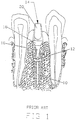
- Fig. 1 shows a prior art system comprising an implant 10 disposed in an osteotomy site in the jaw of a patient.
- Implant 10 has a bore 12 formed with a self-holding taper and mounts therein an abutment 14 having a post portion 16 formed with a matching self-holding taper so that the abutment can be locked in place by tapping the abutment along the longitudinal axis of the post portion with at least a selected force.
- Abutment 14 has a central portion or base 18 formed with a smooth curved outer surface configuration and a head portion 20 which serves to mount a prosthesis thereon.
- a crown or other prosthesis is typically fabricated by a relatively labor intensive and time consuming process involving the burnishing of platinum foil on the head of an abutment which is then built upon and shaped to fit within the space available between contiguous teeth, as shown in Fig. 1 , or prosthesis, and opposing teeth or prosthesis (not shown).
- the foil has to be removed, as by scraping, before the prosthesis can be permanently attached to the abutment mounted in the implant. If cement is used in attaching to the abutment, care must be taken to avoid having extraneous cement on the outer surface which would irritate the gingiva.
- fabricating a prosthesis is simplified by first forming the crown utilizing an abutment analog.
- the abutment analog and the permanent abutment are formed with an identical shelf extending between the upstanding part of the head portion and the crown.
- the crown with or without a sleeve core, is separately fabricated on the analog abutment and formed With an end face having a configuration selected to match the configuration of the shoulder, e.g., having the same slope angle.
- the crown is then received on and cemented to the abutment thereby integrating the crown and abutment so that the prosthesis can be finished and polished extraorally.
- the finished integrated abutment crown preferably having a post portion with a self-holding taper, is then inserted into the implant, its angular orientation adjusted as desired and finally tapped into locking engagement in the implant as a single unit utilizing a customized seating device.
- cement margins between the crown and the abutment portion are entirely eliminated, as will be discussed below.
- an integrated abutment crown 22 is shown having an abutment portion 24 and a crown portion 26 indicated in dashed lines.
- Abutment portion 24 is formed of suitable biocompatible material such as titanium or titanium alloy and has a central portion 24a having a smooth curved surface which typically is circular in a horizontal cross section (as shown in the drawing) but can be of other configurations, such as elliptical. In the following discussion it will be considered as circular for the example given. Central portion 24a has a downwardly (with reference to the orientation shown in the drawing) extending post portion 24b for receipt in the bore of an implant such as shown in Fig. 1 . Although various attachment mechanisms can be employed for attaching the abutment portion to the implant, a generally cylindrical post having a self-holding taper matching a self-holding taper of a bore of the implant, as in the above referenced patents, is preferred.
- a nose 24c extends upwardly from central portion 24a and a shelf 24d extends from the maximum circumferential portion of the central portion to nose 24c and is joined to the nose by a smooth curved surface.
- the nose is generally conical but can be of any suitable configuration for supporting the crown material and has a free end 24e formed with a smooth curved surface.
- the curved smooth surface facilitates the incremental chemical and mechanical addition of various prosthetic materials to be discussed and to minimize stress concentration.
- the outer portion of the shelf may be at a single height about its circumference, i.e., the distance from the extremity of the free portion of the nose being constant about its periphery, or it may be varied, as indicated by dashed line 24f, to adjust to anatomical features, such as following the gingival contour.
- the angle that the outer circumferential portion of the shelf makes with a plane perpendicular to the longitudinal axis of nose 24c can be of any selected degree, however it is preferred that the shelf slope upwardly toward the nose at an angle of between approximately 10 to 40 degrees with the said plane.
- Crown portion 26 is applied directly to the surface of the head portion comprising nose 24c and shelf 24d.
- a suitable non-shouldered abutment portion is selected and tried in an analog implant in a model of the osteotomy site which includes at least adjacent and opposite dentition.
- Implant analogs such as those shown in copending, coassigned application SN 10/093,991, filed 03/07/2002 , can be used.
- the gingival height is marked and shoulder 24d is formed, or a suitable abutment portion having a preformed shoulder is selected.
- the head portion of the abutment portion is preferably sand blasted with suitable media, such as 50 micron alumina oxide, and then cleaned with 95 per cent ethyl alcohol in an ultrasonic bath for approximately five minutes.
- suitable media such as 50 micron alumina oxide
- the abutment portion is air dried with an oil free compressed air source or, if not available, by using a hair dryer.
- a metal coupler #C313 of DRM
- a suitable instrument such as a brush. Air is blown on each of the coats to remove excess liquid and the coats gently dried. A slightly cloudy or milky appearance indicates sufficient coverage.
- the abutment portion is baked in an oven for five minutes at approximately 120 degrees C with no vacuum.
- the abutment portion is then opaqued with a neutral metal opaque powder (#C421 of DRM). This step is required for certain shades and is optional for other shades. Approximately two drops of metal opaque liquid (#C318 of DRM) and one heaping spatular tip of neutral metal opaque powder (#C421 of DRM) is taken with the powder incorporated into the liquid in three incremental steps, and spatulated to form a smooth creamy mix. A single coat is applied and the abutment portion then baked at approximately 120 degrees C for five minutes preferably with a vacuum to increase bond strength. A ceramo coupler (#B204 of DRM) is applied and gently air dried. Ceramo coupler is required between two opaque layers. The abutment portion is bench cooled for one minute and a thin coat of modeling liquid (#C312 of DRM) is applied if a second layer of metal opaque is not going to be applied.
- a neutral metal opaque powder #C421 of DRM
- a second metal opaque layer of appropriate shade may be applied.
- two drops of opaque liquid is incorporated into one heaping spatular tip of neutral opaque powder in three incremental steps and spatulated to form a smooth creamy mix.
- a single coat is applied with a brush. While the degree of mixing is not critical, the coat should be applied quickly.
- the abutment portion is then oven baked at approximately 120 degrees C for five minutes with vacuum; again vacuum is not essential but does increase bond strength.
- the abutment portion is then bench cooled for one minute and then ceramo coupler applied and gently air dried. Modeling liquid (#C312 of DRM) is applied and light cured for two minutes.
- the crown is then built up in four applications of
- a flat strip of opaque dentin (A3 - #C338 of DRM) is patted out on a glass slab; the opaque dentin is applied to the surface extending to the cervical margins all around the abutment portion while avoiding air inclusions; this application is repeated for 40 to 70 per cent of the crown thickness; the result is light cured for four minutes.
- a flat strip of dentin (A3 - #C328 of DRM) is patted out on a glass slab; the dentin is applied directly onto the opaque layer and anatomical features are placed; intrinsic stains are incorporated as required; the result is light cured for two minutes.
- a flat strip of enamel (A3 - #C377 of DRM) is patted out on a glass slab; the enamel is applied directly to the dentin layer; the morphology is shaped and contacts and margins applied; when the intrinsic characterization is completed, the enamel, is light cured for two minutes.
- the incisal (Clear - #311 of DRM) is applied directly onto the enamel and characterized by using different opacities; the morphology is shaped and occlusion is adjusted; after stain pits, fissures etc., the incisal is light cured for two minutes.
- Finishing is performed using a superior grade diamond fine cut carbide bur for obtaining a final unpolished crown. Polishing is then performed using silicone discs to remove oxide layers and cuts, a nylon bristle brush for smoothing the surface and a buff wheel used with paste.
- Repairs to existing integrated abutment crowns can be made intraorally by reducing existing material as necessary, then cleaning with 95 per cent ethyl alcohol and air drying, applying ceramo coupler and drying and then applying modeling liquid, light curing for one minute and adding appropriate material, as described above. Such repairs can result from a need to add a contact point, alter the crown contour, correct the color of the post having undergone a color change, join adjacent units and repair fractures or seating divets.
- angulated integrated abutment crowns made in accordance with the invention can be notched to provide a directional seating platform. Subsequently the resulting divot can be re-contoured after seating of the prosthesis.
- various materials can be used for fabricating the crown by directly bonding or attaching the material by chemical or mechanical means without the use of cement, for example, ceramics and porcelains, polymers, polyceramic resins, glass ionomers and other composite materials which are capable of being chromatically and aesthetically similar to adjacent dentition as well as having the ability of withstanding the various forces of mastication, bruxing and light trauma and can be cured by means which are not injurious to the material of the crown or the abutment while having sufficient bonding to the abutment portion. It will be realized that the specific steps of application would be adjusted for the particular materials selected, as required.
- the invention also provides the ability to add prosthetic material only to a portion of the head portion of the abutment portion since a sleeve is not required, as well as to add prosthetic material below the height of contour of the abutment portion which is not possible with sleeve type systems.
- a method for providing an integrated abutment crown is provided in which materials in various forms can be used in providing different characterizations as well as an abutment portion that has dimensions consistent with clinical realities.
- abutment portion could be attached to the abutment portion to facilitate the efficiency and accuracy of fabrication of the prosthesis.
- abutments also can be preformed with a shelf, if desired.
- several standard variations could be provided to fit different requirements. This approach would allow making the abutment in a more easily controlled high quality environment and to make it convenient and more expeditious for the addition of the crown material. It is therefore the intention that the appended claims be interpreted as broadly as possible in view of the prior art to include all such variations and modification.
Landscapes
- Health & Medical Sciences (AREA)
- Oral & Maxillofacial Surgery (AREA)
- Dentistry (AREA)
- Epidemiology (AREA)
- Life Sciences & Earth Sciences (AREA)
- Animal Behavior & Ethology (AREA)
- General Health & Medical Sciences (AREA)
- Public Health (AREA)
- Veterinary Medicine (AREA)
- Orthopedic Medicine & Surgery (AREA)
- Plastic & Reconstructive Surgery (AREA)
- Dental Prosthetics (AREA)
Claims (7)
- Pilier (22) destiné à être utilisé avec un implant (10), ledit implant présentant une première extrémité et une seconde extrémité, un axe longitudinal traversant la première extrémité, et un alésage (12) formé à travers la première extrémité et s'étendant le long de l'axe longitudinal, le pilier comprenant une partie centrale (24a) située entre une partie de tige (24b) et une partie de tête (24c, 24d), la partie de tige (24b) ayant un axe longitudinal et pouvant être accueillie dans l'alésage dudit implant (10), la partie centrale (24a) étant formée avec une surface extérieure légèrement incurvée qui s'étend à partir d'un diamètre relativement important pour atteindre progressivement un diamètre inférieur où la partie centrale rejoint la partie de tige, la partie de tête ayant un axe longitudinal et présentant un nez (24c) qui s'étend le long de l'axe longitudinal jusqu'à une extrémité libre (24e),
un plateau (24d) étant formé entre la partie centrale (24a) et le nez (24c),
le plateau (24d) ayant une partie externe et une partie interne, la partie externe formant un angle choisi avec un plan perpendiculaire à l'axe longitudinal de la partie de tête et la partie interne formant une surface légèrement incurvée avec le nez (24c), le plateau (24d) et le nez (24c) étant conçus pour supporter le matériau de la couronne qu'ils accueillent ; caractérisé en ce que :l'extrémité libre (24e) du nez est arrondie ; etla partie centrale (24a) présente une circonférence et la distance qui sépare l'extrémité libre du nez (24c) et la partie externe du plateau (24d) varie suivant la circonférence de la partie centrale (24a) conformément à un profil gingival choisi. - Pilier (22) selon la revendication 1, dans lequel les axes longitudinaux de la partie de tête (24c, 24d) et de la partie de tige (24b) sont principalement colinéaires.
- Pilier (22) selon la revendication 1, dans lequel les axes longitudinaux de la partie de tête (24c, 24d) et de la partie de tige (24b) ne sont pas colinéaires.
- Pilier (22) selon la revendication 1, dans lequel la partie de tige (24b) est cylindrique sans biseau et est apte à être fixée sur un implant (10) grâce à un moyen de fixation.
- Pilier (22) selon la revendication 1, dans lequel la partie de tête (24c, 24d) comporte une surface rugueuse afin d'augmenter la rétention du matériau prosthétique appliqué directement sur la surface du pilier.
- Pilier (22) selon la revendication 1, comprenant en outre un matériau prosthétique comprenant une couche opaque appliquée sur la partie de tête (24c, 24d) et comprenant en outre une pièce prosthétique en forme de dent lui permettant de s'adapter sur la partie de tête en vue d'une fixation ultérieure sur celle-ci et conçue pour une sculpture et un polissage finals afin de correspondre à une application clinique spécifique.
- Pilier (22) selon la revendication 1, comprenant en outre un matériau prosthétique appliqué sur la partie de tête (24c, 24d).
Applications Claiming Priority (2)
| Application Number | Priority Date | Filing Date | Title |
|---|---|---|---|
| US10/662,624 US6991462B2 (en) | 2002-09-16 | 2003-09-15 | Dental implant system and method |
| PCT/US2004/028378 WO2005032392A2 (fr) | 2003-09-15 | 2004-08-30 | Systeme et procede d'implant dentaire |
Publications (3)
| Publication Number | Publication Date |
|---|---|
| EP1663045A2 EP1663045A2 (fr) | 2006-06-07 |
| EP1663045A4 EP1663045A4 (fr) | 2009-06-03 |
| EP1663045B1 true EP1663045B1 (fr) | 2016-04-20 |
Family
ID=34421965
Family Applications (1)
| Application Number | Title | Priority Date | Filing Date |
|---|---|---|---|
| EP04782797.7A Not-in-force EP1663045B1 (fr) | 2003-09-15 | 2004-08-30 | Systeme d'implant dentaire |
Country Status (10)
| Country | Link |
|---|---|
| US (1) | US6991462B2 (fr) |
| EP (1) | EP1663045B1 (fr) |
| JP (1) | JP2007505649A (fr) |
| KR (1) | KR20060082079A (fr) |
| BR (1) | BRPI0414316B1 (fr) |
| CA (1) | CA2534455C (fr) |
| HK (1) | HK1084316A1 (fr) |
| IL (1) | IL173469A0 (fr) |
| WO (1) | WO2005032392A2 (fr) |
| ZA (1) | ZA200601221B (fr) |
Families Citing this family (16)
| Publication number | Priority date | Publication date | Assignee | Title |
|---|---|---|---|---|
| US7291013B2 (en) * | 2002-06-28 | 2007-11-06 | Zimmer Dental, Inc. | Organic shaped interface for dental implant devices |
| WO2004054464A2 (fr) * | 2002-12-13 | 2004-07-01 | Stefan Neumeyer | Pilier pour un implant dentaire, implant dentaire comprenant un tel pilier et procede pour produire une prothese dentaire par utilisation de cet implant dentaire |
| US7179089B2 (en) * | 2003-10-20 | 2007-02-20 | Prosthosolve, Llc | Abutment system and method for preparing the same |
| US20080206709A1 (en) * | 2007-02-27 | 2008-08-28 | Lannan William G | Gingival support sleeve |
| WO2010022541A1 (fr) * | 2008-08-27 | 2010-03-04 | 辰庚事业有限公司 | Prothèse dentaire artificielle complétée et implantée en une fois avec fontion rapide et technologie pour celle-ci |
| KR100912271B1 (ko) * | 2008-10-20 | 2009-08-17 | 주식회사 쎄타텍 | 크라운 일체형 지대주 및 그 제작방법 |
| WO2011056450A2 (fr) * | 2009-10-28 | 2011-05-12 | 3M Innovative Properties Company | Articles de type implants dentaires et procédés associés |
| EP2603161A1 (fr) * | 2010-08-11 | 2013-06-19 | 3M Innovative Properties Company | Couronnes dentaires revêtues et leur procédé de fabrication |
| EP2603159A1 (fr) | 2010-08-11 | 2013-06-19 | 3M Innovative Properties Company | Articles dentaires dotés d'un revêtement esthétique et résistant à l'abrasion et leurs procédés de fabrication |
| WO2012027091A1 (fr) | 2010-08-11 | 2012-03-01 | 3M Innovative Properties Company | Articles dentaires comprenant revêtement céramique et à microparticules et leur procédé de fabrication |
| ES2363021B1 (es) * | 2010-12-27 | 2012-02-24 | Terrats Mecanizados, S.L. | Aditamiento protésico mejorado. |
| ES2391184B1 (es) * | 2011-04-28 | 2013-10-02 | Medical Media Training S.L. | Pilar dental. |
| TWI524881B (zh) | 2011-08-12 | 2016-03-11 | 王濟源 | 能夠收容以多種角度製作的核冠並在附著帽後用作牙齦成形器的基台和利用該基台的種植體補綴物的製作方法 |
| US8747112B2 (en) | 2011-12-30 | 2014-06-10 | Nobel Biocare Services Ag | Abutment position locator |
| ITMI20132131A1 (it) * | 2013-12-19 | 2015-06-20 | Heraeus Kulzer Gmbh | Procedimento di stratificazione sopra un'interfaccia sagomata per la realizzazione di sovrastrutture di tipo migliorato per protesi e sovrastruttura per protesi dentale realizzata con questo procedimento |
| US10098712B2 (en) * | 2015-01-07 | 2018-10-16 | Bicon, Llc | Integrated dental implant abutments |
Family Cites Families (9)
| Publication number | Priority date | Publication date | Assignee | Title |
|---|---|---|---|---|
| USRE33796E (en) * | 1987-01-28 | 1992-01-14 | Core-Vent Corporation | Coping insert for use with a dental implant |
| US5007835A (en) * | 1989-08-17 | 1991-04-16 | Maurice Valen | Dental implant |
| US5125839A (en) * | 1990-09-28 | 1992-06-30 | Abraham Ingber | Dental implant system |
| GB2274062B (en) * | 1993-01-07 | 1996-11-13 | Leeds Precision Components Ltd | Tooth securement |
| US5376004A (en) * | 1993-11-18 | 1994-12-27 | Mena; Raul | Dental implant device |
| DE19620394C1 (de) * | 1996-05-21 | 1997-09-18 | Degussa | Prothetischer Aufbaupfosten für Zahnimplantate |
| US6290500B1 (en) * | 1997-12-10 | 2001-09-18 | Diro, Inc. | Dental implant system and method |
| US6592370B2 (en) * | 2000-09-14 | 2003-07-15 | Diro, Inc. | Abutment for dental implant and associated components for use therewith |
| KR100440680B1 (ko) * | 2002-01-15 | 2004-07-21 | 주식회사 내이 | 인공치아 구조 |
-
2003
- 2003-09-15 US US10/662,624 patent/US6991462B2/en not_active Expired - Lifetime
-
2004
- 2004-08-30 ZA ZA200601221A patent/ZA200601221B/en unknown
- 2004-08-30 WO PCT/US2004/028378 patent/WO2005032392A2/fr active Application Filing
- 2004-08-30 CA CA2534455A patent/CA2534455C/fr not_active Expired - Fee Related
- 2004-08-30 BR BRPI0414316A patent/BRPI0414316B1/pt not_active IP Right Cessation
- 2004-08-30 EP EP04782797.7A patent/EP1663045B1/fr not_active Not-in-force
- 2004-08-30 JP JP2006526159A patent/JP2007505649A/ja active Pending
- 2004-08-30 KR KR1020067005193A patent/KR20060082079A/ko not_active Application Discontinuation
-
2006
- 2006-01-31 IL IL173469A patent/IL173469A0/en not_active IP Right Cessation
- 2006-06-13 HK HK06106731.5A patent/HK1084316A1/zh not_active IP Right Cessation
Also Published As
| Publication number | Publication date |
|---|---|
| BRPI0414316A (pt) | 2006-10-31 |
| WO2005032392A2 (fr) | 2005-04-14 |
| US20040063070A1 (en) | 2004-04-01 |
| ZA200601221B (en) | 2007-06-27 |
| IL173469A0 (en) | 2006-06-11 |
| WO2005032392A3 (fr) | 2006-05-18 |
| KR20060082079A (ko) | 2006-07-14 |
| HK1084316A1 (zh) | 2006-07-28 |
| CA2534455A1 (fr) | 2005-04-14 |
| CA2534455C (fr) | 2013-05-21 |
| WO2005032392B1 (fr) | 2006-07-20 |
| JP2007505649A (ja) | 2007-03-15 |
| BRPI0414316B1 (pt) | 2016-07-12 |
| EP1663045A2 (fr) | 2006-06-07 |
| US6991462B2 (en) | 2006-01-31 |
| EP1663045A4 (fr) | 2009-06-03 |
Similar Documents
| Publication | Publication Date | Title |
|---|---|---|
| US6290500B1 (en) | Dental implant system and method | |
| EP1663045B1 (fr) | Systeme d'implant dentaire | |
| US5419702A (en) | Dental restoration on artificial root fixtures | |
| US7179089B2 (en) | Abutment system and method for preparing the same | |
| US5846079A (en) | Single tooth dental restoration system | |
| EP1523284B1 (fr) | Prothèse dentale | |
| US6666684B1 (en) | Impression and foundation system for implant-supported prosthesis | |
| US6325628B1 (en) | Temporary implant components, system and method | |
| CA2600556C (fr) | Assemblage de pivot pour un implant dentaire | |
| US20020168613A1 (en) | Near net tooth shaped ceramic crown | |
| US20090081618A1 (en) | System and method for immediate loading of fixed hybrid dental prostheses | |
| KR20170023890A (ko) | 맞춤형 치과용 임플란트 어버트먼트 및 임프레션 포스트 용 몰드 | |
| US20150173864A1 (en) | Abutment assembly for dental implants | |
| US20090017421A1 (en) | Method of Preparing an Artificial Dental Prosthetic and Seating Thereof | |
| USRE36126E (en) | Dental restoration on artificial root fixtures | |
| US20080008981A1 (en) | Abutment set for a dental implant | |
| US20160346066A1 (en) | Margin Ring and Method of Making Dental Crown Using the Margin Ring | |
| CN114145868A (zh) | 全瓷制作的可摘义齿结构及其制作方法 | |
| CN212592509U (zh) | 多植体修复的被动位夹具 | |
| Ozkan et al. | Stud Attachments Used in Tooth-Supported Overdenture | |
| Restorations | 13 Laboratory Fabrication of Full-Arch Implant-Supported Restorations | |
| Messing et al. | The Crowning of Vital Teeth |
Legal Events
| Date | Code | Title | Description |
|---|---|---|---|
| PUAI | Public reference made under article 153(3) epc to a published international application that has entered the european phase |
Free format text: ORIGINAL CODE: 0009012 |
|
| PUAK | Availability of information related to the publication of the international search report |
Free format text: ORIGINAL CODE: 0009015 |
|
| 17P | Request for examination filed |
Effective date: 20060316 |
|
| AK | Designated contracting states |
Kind code of ref document: A2 Designated state(s): AT BE BG CH CY CZ DE DK EE ES FI FR GB GR HU IE IT LI LU MC NL PL PT RO SE SI SK TR |
|
| AX | Request for extension of the european patent |
Extension state: AL HR LT LV MK |
|
| REG | Reference to a national code |
Ref country code: HK Ref legal event code: DE Ref document number: 1084316 Country of ref document: HK |
|
| RIC1 | Information provided on ipc code assigned before grant |
Ipc: A61C 8/00 20060101AFI20060627BHEP |
|
| R17D | Deferred search report published (corrected) |
Effective date: 20060720 |
|
| RIC1 | Information provided on ipc code assigned before grant |
Ipc: A61C 5/10 20060101AFI20060913BHEP Ipc: A61C 13/087 20060101ALI20060913BHEP Ipc: A61C 8/00 20060101ALI20060913BHEP Ipc: A61C 13/083 20060101ALI20060913BHEP |
|
| R17D | Deferred search report published (corrected) |
Effective date: 20060518 |
|
| DAX | Request for extension of the european patent (deleted) | ||
| R17D | Deferred search report published (corrected) |
Effective date: 20060720 |
|
| A4 | Supplementary search report drawn up and despatched |
Effective date: 20090507 |
|
| 17Q | First examination report despatched |
Effective date: 20091217 |
|
| GRAP | Despatch of communication of intention to grant a patent |
Free format text: ORIGINAL CODE: EPIDOSNIGR1 |
|
| INTG | Intention to grant announced |
Effective date: 20151028 |
|
| GRAS | Grant fee paid |
Free format text: ORIGINAL CODE: EPIDOSNIGR3 |
|
| GRAA | (expected) grant |
Free format text: ORIGINAL CODE: 0009210 |
|
| AK | Designated contracting states |
Kind code of ref document: B1 Designated state(s): AT BE BG CH CY CZ DE DK EE ES FI FR GB GR HU IE IT LI LU MC NL PL PT RO SE SI SK TR |
|
| REG | Reference to a national code |
Ref country code: GB Ref legal event code: FG4D |
|
| REG | Reference to a national code |
Ref country code: CH Ref legal event code: EP Ref country code: DE Ref legal event code: R081 Ref document number: 602004049118 Country of ref document: DE Owner name: BICON, LLC, BOSTON, US Free format text: FORMER OWNER: DEBBIE, LLC., BOSTON, MASS., US |
|
| REG | Reference to a national code |
Ref country code: AT Ref legal event code: REF Ref document number: 791527 Country of ref document: AT Kind code of ref document: T Effective date: 20160515 |
|
| REG | Reference to a national code |
Ref country code: IE Ref legal event code: FG4D |
|
| REG | Reference to a national code |
Ref country code: DE Ref legal event code: R096 Ref document number: 602004049118 Country of ref document: DE |
|
| REG | Reference to a national code |
Ref country code: AT Ref legal event code: MK05 Ref document number: 791527 Country of ref document: AT Kind code of ref document: T Effective date: 20160420 |
|
| REG | Reference to a national code |
Ref country code: NL Ref legal event code: MP Effective date: 20160420 |
|
| PG25 | Lapsed in a contracting state [announced via postgrant information from national office to epo] |
Ref country code: PL Free format text: LAPSE BECAUSE OF FAILURE TO SUBMIT A TRANSLATION OF THE DESCRIPTION OR TO PAY THE FEE WITHIN THE PRESCRIBED TIME-LIMIT Effective date: 20160420 Ref country code: NL Free format text: LAPSE BECAUSE OF FAILURE TO SUBMIT A TRANSLATION OF THE DESCRIPTION OR TO PAY THE FEE WITHIN THE PRESCRIBED TIME-LIMIT Effective date: 20160420 Ref country code: FI Free format text: LAPSE BECAUSE OF FAILURE TO SUBMIT A TRANSLATION OF THE DESCRIPTION OR TO PAY THE FEE WITHIN THE PRESCRIBED TIME-LIMIT Effective date: 20160420 |
|
| REG | Reference to a national code |
Ref country code: DE Ref legal event code: R079 Ref document number: 602004049118 Country of ref document: DE Free format text: PREVIOUS MAIN CLASS: A61C0005100000 Ipc: A61C0005770000 |
|
| PG25 | Lapsed in a contracting state [announced via postgrant information from national office to epo] |
Ref country code: AT Free format text: LAPSE BECAUSE OF FAILURE TO SUBMIT A TRANSLATION OF THE DESCRIPTION OR TO PAY THE FEE WITHIN THE PRESCRIBED TIME-LIMIT Effective date: 20160420 Ref country code: GR Free format text: LAPSE BECAUSE OF FAILURE TO SUBMIT A TRANSLATION OF THE DESCRIPTION OR TO PAY THE FEE WITHIN THE PRESCRIBED TIME-LIMIT Effective date: 20160721 Ref country code: ES Free format text: LAPSE BECAUSE OF FAILURE TO SUBMIT A TRANSLATION OF THE DESCRIPTION OR TO PAY THE FEE WITHIN THE PRESCRIBED TIME-LIMIT Effective date: 20160420 Ref country code: SE Free format text: LAPSE BECAUSE OF FAILURE TO SUBMIT A TRANSLATION OF THE DESCRIPTION OR TO PAY THE FEE WITHIN THE PRESCRIBED TIME-LIMIT Effective date: 20160420 Ref country code: PT Free format text: LAPSE BECAUSE OF FAILURE TO SUBMIT A TRANSLATION OF THE DESCRIPTION OR TO PAY THE FEE WITHIN THE PRESCRIBED TIME-LIMIT Effective date: 20160822 |
|
| PG25 | Lapsed in a contracting state [announced via postgrant information from national office to epo] |
Ref country code: BE Free format text: LAPSE BECAUSE OF FAILURE TO SUBMIT A TRANSLATION OF THE DESCRIPTION OR TO PAY THE FEE WITHIN THE PRESCRIBED TIME-LIMIT Effective date: 20160420 |
|
| REG | Reference to a national code |
Ref country code: DE Ref legal event code: R097 Ref document number: 602004049118 Country of ref document: DE |
|
| PG25 | Lapsed in a contracting state [announced via postgrant information from national office to epo] |
Ref country code: DK Free format text: LAPSE BECAUSE OF FAILURE TO SUBMIT A TRANSLATION OF THE DESCRIPTION OR TO PAY THE FEE WITHIN THE PRESCRIBED TIME-LIMIT Effective date: 20160420 Ref country code: EE Free format text: LAPSE BECAUSE OF FAILURE TO SUBMIT A TRANSLATION OF THE DESCRIPTION OR TO PAY THE FEE WITHIN THE PRESCRIBED TIME-LIMIT Effective date: 20160420 Ref country code: CZ Free format text: LAPSE BECAUSE OF FAILURE TO SUBMIT A TRANSLATION OF THE DESCRIPTION OR TO PAY THE FEE WITHIN THE PRESCRIBED TIME-LIMIT Effective date: 20160420 Ref country code: RO Free format text: LAPSE BECAUSE OF FAILURE TO SUBMIT A TRANSLATION OF THE DESCRIPTION OR TO PAY THE FEE WITHIN THE PRESCRIBED TIME-LIMIT Effective date: 20160420 Ref country code: SK Free format text: LAPSE BECAUSE OF FAILURE TO SUBMIT A TRANSLATION OF THE DESCRIPTION OR TO PAY THE FEE WITHIN THE PRESCRIBED TIME-LIMIT Effective date: 20160420 |
|
| PLBE | No opposition filed within time limit |
Free format text: ORIGINAL CODE: 0009261 |
|
| STAA | Information on the status of an ep patent application or granted ep patent |
Free format text: STATUS: NO OPPOSITION FILED WITHIN TIME LIMIT |
|
| 26N | No opposition filed |
Effective date: 20170123 |
|
| PG25 | Lapsed in a contracting state [announced via postgrant information from national office to epo] |
Ref country code: MC Free format text: LAPSE BECAUSE OF FAILURE TO SUBMIT A TRANSLATION OF THE DESCRIPTION OR TO PAY THE FEE WITHIN THE PRESCRIBED TIME-LIMIT Effective date: 20160420 |
|
| REG | Reference to a national code |
Ref country code: CH Ref legal event code: PL |
|
| PG25 | Lapsed in a contracting state [announced via postgrant information from national office to epo] |
Ref country code: CH Free format text: LAPSE BECAUSE OF NON-PAYMENT OF DUE FEES Effective date: 20160831 Ref country code: LI Free format text: LAPSE BECAUSE OF NON-PAYMENT OF DUE FEES Effective date: 20160831 |
|
| REG | Reference to a national code |
Ref country code: FR Ref legal event code: ST Effective date: 20170428 |
|
| PG25 | Lapsed in a contracting state [announced via postgrant information from national office to epo] |
Ref country code: SI Free format text: LAPSE BECAUSE OF FAILURE TO SUBMIT A TRANSLATION OF THE DESCRIPTION OR TO PAY THE FEE WITHIN THE PRESCRIBED TIME-LIMIT Effective date: 20160420 |
|
| REG | Reference to a national code |
Ref country code: IE Ref legal event code: MM4A |
|
| REG | Reference to a national code |
Ref country code: HK Ref legal event code: GR Ref document number: 1084316 Country of ref document: HK |
|
| PG25 | Lapsed in a contracting state [announced via postgrant information from national office to epo] |
Ref country code: FR Free format text: LAPSE BECAUSE OF NON-PAYMENT OF DUE FEES Effective date: 20160831 Ref country code: IE Free format text: LAPSE BECAUSE OF NON-PAYMENT OF DUE FEES Effective date: 20160830 |
|
| PG25 | Lapsed in a contracting state [announced via postgrant information from national office to epo] |
Ref country code: LU Free format text: LAPSE BECAUSE OF NON-PAYMENT OF DUE FEES Effective date: 20160830 |
|
| REG | Reference to a national code |
Ref country code: DE Ref legal event code: R082 Ref document number: 602004049118 Country of ref document: DE Representative=s name: MEISSNER BOLTE PATENTANWAELTE RECHTSANWAELTE P, DE Ref country code: DE Ref legal event code: R081 Ref document number: 602004049118 Country of ref document: DE Owner name: BICON, LLC, BOSTON, US Free format text: FORMER OWNER: DEBBIE, LLC., BOSTON, MASS., US |
|
| REG | Reference to a national code |
Ref country code: GB Ref legal event code: 732E Free format text: REGISTERED BETWEEN 20180308 AND 20180314 |
|
| PG25 | Lapsed in a contracting state [announced via postgrant information from national office to epo] |
Ref country code: HU Free format text: LAPSE BECAUSE OF FAILURE TO SUBMIT A TRANSLATION OF THE DESCRIPTION OR TO PAY THE FEE WITHIN THE PRESCRIBED TIME-LIMIT; INVALID AB INITIO Effective date: 20040830 Ref country code: CY Free format text: LAPSE BECAUSE OF FAILURE TO SUBMIT A TRANSLATION OF THE DESCRIPTION OR TO PAY THE FEE WITHIN THE PRESCRIBED TIME-LIMIT Effective date: 20160420 |
|
| PG25 | Lapsed in a contracting state [announced via postgrant information from national office to epo] |
Ref country code: TR Free format text: LAPSE BECAUSE OF FAILURE TO SUBMIT A TRANSLATION OF THE DESCRIPTION OR TO PAY THE FEE WITHIN THE PRESCRIBED TIME-LIMIT Effective date: 20160420 |
|
| PG25 | Lapsed in a contracting state [announced via postgrant information from national office to epo] |
Ref country code: BG Free format text: LAPSE BECAUSE OF FAILURE TO SUBMIT A TRANSLATION OF THE DESCRIPTION OR TO PAY THE FEE WITHIN THE PRESCRIBED TIME-LIMIT Effective date: 20160420 |
|
| PGFP | Annual fee paid to national office [announced via postgrant information from national office to epo] |
Ref country code: DE Payment date: 20180829 Year of fee payment: 15 Ref country code: IT Payment date: 20180822 Year of fee payment: 15 |
|
| PGFP | Annual fee paid to national office [announced via postgrant information from national office to epo] |
Ref country code: GB Payment date: 20180828 Year of fee payment: 15 |
|
| REG | Reference to a national code |
Ref country code: DE Ref legal event code: R119 Ref document number: 602004049118 Country of ref document: DE |
|
| GBPC | Gb: european patent ceased through non-payment of renewal fee |
Effective date: 20190830 |
|
| PG25 | Lapsed in a contracting state [announced via postgrant information from national office to epo] |
Ref country code: DE Free format text: LAPSE BECAUSE OF NON-PAYMENT OF DUE FEES Effective date: 20200303 |
|
| PG25 | Lapsed in a contracting state [announced via postgrant information from national office to epo] |
Ref country code: GB Free format text: LAPSE BECAUSE OF NON-PAYMENT OF DUE FEES Effective date: 20190830 Ref country code: IT Free format text: LAPSE BECAUSE OF NON-PAYMENT OF DUE FEES Effective date: 20190830 |