EP1662678B1 - TDMA-Kommunikationsvorrichtung - Google Patents
TDMA-Kommunikationsvorrichtung Download PDFInfo
- Publication number
- EP1662678B1 EP1662678B1 EP05257258A EP05257258A EP1662678B1 EP 1662678 B1 EP1662678 B1 EP 1662678B1 EP 05257258 A EP05257258 A EP 05257258A EP 05257258 A EP05257258 A EP 05257258A EP 1662678 B1 EP1662678 B1 EP 1662678B1
- Authority
- EP
- European Patent Office
- Prior art keywords
- slot
- time
- station
- transmit
- out value
- Prior art date
- Legal status (The legal status is an assumption and is not a legal conclusion. Google has not performed a legal analysis and makes no representation as to the accuracy of the status listed.)
- Ceased
Links
Images


Classifications
-
- H—ELECTRICITY
- H04—ELECTRIC COMMUNICATION TECHNIQUE
- H04B—TRANSMISSION
- H04B7/00—Radio transmission systems, i.e. using radiation field
- H04B7/24—Radio transmission systems, i.e. using radiation field for communication between two or more posts
- H04B7/26—Radio transmission systems, i.e. using radiation field for communication between two or more posts at least one of which is mobile
- H04B7/2643—Radio transmission systems, i.e. using radiation field for communication between two or more posts at least one of which is mobile using time-division multiple access [TDMA]
- H04B7/2656—Radio transmission systems, i.e. using radiation field for communication between two or more posts at least one of which is mobile using time-division multiple access [TDMA] for structure of frame, burst
-
- H—ELECTRICITY
- H04—ELECTRIC COMMUNICATION TECHNIQUE
- H04W—WIRELESS COMMUNICATION NETWORKS
- H04W28/00—Network traffic management; Network resource management
- H04W28/16—Central resource management; Negotiation of resources or communication parameters, e.g. negotiating bandwidth or QoS [Quality of Service]
- H04W28/26—Resource reservation
-
- H—ELECTRICITY
- H04—ELECTRIC COMMUNICATION TECHNIQUE
- H04W—WIRELESS COMMUNICATION NETWORKS
- H04W72/00—Local resource management
- H04W72/04—Wireless resource allocation
-
- H—ELECTRICITY
- H04—ELECTRIC COMMUNICATION TECHNIQUE
- H04W—WIRELESS COMMUNICATION NETWORKS
- H04W74/00—Wireless channel access
- H04W74/04—Scheduled access
Definitions
- the present invention relates generally to a Time Division Multiple Access (TDMA) communications apparatus for performing TDMA communication in which each frame is divided into a plurality of time slots and every participating station transmits information in allocated slots. More particularly, the invention pertains to slot allocation for a TDMA communications apparatus.
- TDMA Time Division Multiple Access
- each successive frame is divided into a plurality of time slots based on a common time reference (time base) obtained from the global positioning system (GPS), for example, according to a prescribed time division scheme to thereby establish accurate slot synchronization among a plurality of participating stations (e.g. mobile units such as ships).
- the participating stations carry out TDMA communication while reserving (allocating) slots for their own transmission of information and messages.
- this kind of communication system such as the Universal Automatic Identification System (UAIS)
- UAIS Universal Automatic Identification System
- it is essential for every participating station to communicate data in accordance with a defined protocol.
- SOTDMA Self-Organized Time Division Multiple Access
- a participating station When transmitting a message in a slot in a particular frame, a participating station can announce a time-out value together with a slot number to be reserved for future transmissions.
- the time-out value thus announced which is normally selected from a range of "3" to "7", is a preliminary indication of the station's intention to use the same slot in several frames succeeding to the current frame.
- one station selects and announces a time-out value "4" when transmitting a message in a particular slot in the current frame, for example, that station successively reserves the same slot in the four succeeding frames while decrementing the time-out value from "4" to "3", "2", "1" and "0".
- the station announces the time-out value "4" when transmitting a message in a slot in a first frame.
- the station announces the time-out value "3" and definitely reserves the same slot in a third frame when transmitting a message in a second frame.
- the station announces the time-out value "2" and definitely reserves the same slot in a fourth frame when transmitting a message in the third frame.
- the station announces the time-out value "1" and definitely reserves the same slot in a fifth frame when transmitting a message in the fourth frame.
- the station announces the time-out value "0" when transmitting a message in the fifth frame.
- a TDMA communications apparatus preliminarily reserves, or pre-reserves, the same slot in as many successive frames as specified by the time-out value and definitely reserves, or allocates, that slot at a point of transmission in the slot in each successive frame while decrementing the time-out value by 1.
- the TDMA communications apparatus of each station decrements the time-out value one by one in this fashion, all other stations can recognize for how many frames the relevant slot should not be allocated for their own use referring to the time-out value transmitted from that TDMA communications apparatus.
- the TDMA communications apparatus selects and announces a desired slot number specifying a slot to be pre-preserved for future transmissions and announces that slot number together with a new time-out value when transmitting a message as described in Japanese Patent Application Publication No. 2003-057579 , for example.
- FIG. 6 is an explanatory diagram showing a transmit slot allocation conflict which can occur under the currently used SOTDMA protocol.
- station A and station B transmits in two successive slots (e.g., slot No. 100 and slot No. 101) in a particular frame and the time-out value reaches a specific value ("0" in a case where the time-out value is decremented from one frame to the next as stated above) on both stations A, B in the same frame, there is a possibility that a slot number specifying a slot to be pre-preserved for future transmissions by station A coincides (conflicts) with a slot number specifying a slot to be pre-preserved for future transmissions by station B.
- a transmitter section of station A edits a transmit message including a slot number (slot No. 99 in frame c as illustrated in FIG. 6 ) to be pre-preserved for future transmissions and a time-out value. Then, station A transmits the message to station B and other participating stations in slot No. 100.
- a receiver section of station B receives the message transmitted by station A in slot No. 100 and analyzes the message in slot No. 101. Therefore, station B recognizes the next slot number (slot No. 99 in frame c as illustrated in FIG. 6 ) to be allocated to station A at a point in time in slot No. 101.
- a transmitter section of station B edits a transmit message including a slot number (slot No. 99 in frame c as illustrated in FIG. 6 ) to be pre-preserved for future transmissions and a time-out value. Then, station B transmits the message the other participating stations in slot No. 101.
- station B may select and announce a slot number (slot No. 99 in frame c as illustrated in FIG. 6 ) specifying the slot to be pre-preserved for future transmissions before knowing that station A has pre-preserved the same slot for future transmissions. Should such a situation occur, the slot number allocated to station A conflicts with the slot number allocated to station B.
- slot number slot No. 99 in frame c as illustrated in FIG. 6
- a TDMA communications apparatus for carrying out communication with one or more other such apparatus using TDMA technology in which a frame is divided into a plurality of slots in accordance with a prescribed time division scheme, said apparatus being arranged to transmit in the same slot allocated in as many successive frames as specified by a time-out value which is decremented by 1 from one frame to the next, said apparatus including processing means (1) for reserving a new slot for future transmissions together with an initial time-out value at a point in time when a previously set time-out value reaches a specific value, characterised in that said processing means (1) is arranged to detect a time-out value set by any other apparatus for either of the slots adjacent to the slot to be allocated by said one apparatus and to set the initial time-out value at a value differing from the detected time-out value of the other apparatus for the slot of said apparatus to be allocated at a point in time when the one apparatus reserves the new slot.
- the TDMA communications apparatus thus structured examines whether transmit slots adjacent to a transmit slot to be pre-reserved for future transmissions by the own station are pre-reserved by any of other stations when the own station is going to set a slot number specifying the transmit slot to be pre-reserved. If either of the transmit slots adjacent to the transmit slot to be pre-reserved for own use is pre-reserved by any of the other stations, the TDMA communications apparatus finds out the time-out value set for each of the adjacent transmit slots.
- the TDMA communications apparatus sets for own future transmissions an initial time-out value different from the time-out value set by any of the other stations and transmits the initial time-out value together with the slot number specifying the transmit slot to be pre-reserved for the own station. If TDMA communication is carried out in autonomous and continuous mode in this form of transmit slot allocation scheme, the same time-out value is not set in three successive slots including the transmit slot to be pre-reserved for the own station and it is also possible to prevent two stations from reserving two successive slots for their future transmissions.
- the processing means may be arranged to cancel transmission in the newly reserved slot if it detects that the time-out value set by another apparatus for a slot adjacent to the slot of said one apparatus to be allocated has reached said specific value in a slot in which the time-out value of said one apparatus has also reached said specific value, and further to detect in a succeeding slot that the slot newly reserved by the one apparatus for future transmissions coincides with a slot newly reserved by the other station, the time-out value of which has reached said same specific value.
- the processing means cancels transmission in the newly reserved slot if it detects that the time-out value set by the other station for a slot adjacent to the slot of own station to be allocated has reached the aforementioned specific value in a slot in which the time-out value of the own station has also reached the specific value and further detects in a succeeding slot that the slot newly reserved by the own station for future transmissions coincides with a slot newly reserved by the other station of which time-out value has reached the same specific value. This serves to prevent transmit slot allocation conflict even when the same transmit slot is reserved by the own station and another station.
- the processing means may be arranged to reset the time-out value of the one apparatus to said specific value if it detects that the time-out value set for the slot newly reserved for the one apparatus coincides with the time-out value set by the other apparatus for a newly reserved slot thereof adjacent to the slot of the one apparatus to be allocated.
- the processing means resets the time-out value of the own station to the aforementioned specific value if the time-out value set for the slot newly reserved by the own station coincides with the time-out value set by the other station for a newly reserved slot thereof adjacent to the slot of the own station to be allocated even when the time-out value set by the own station is equal to the aforementioned specific value. According to this arrangement, even if another station reserves a slot adjacent to the slot reserved by the own station with the same time-out value as the own station after the own station has reserved a slot with a different time-out value set by another station, the processing means resets the time-out value of the own station. Thus, time-out values of two adjacent slots do not coincide with each other.
- time-out values of two stations which transmit in two successive slots do not simultaneously become the aforementioned specific value. Therefore, the two stations do not reserve their new transmit slots in the two successive slots and this prevents the two stations from reserving the same transmit slot for future transmissions in a reliable manner. Accordingly, it is possible to structure a TDMA communications apparatus which can carry out TDMA communication while preventing transmit slot allocation conflicts in a reliable fashion.
- a TDMA communications apparatus constructed in accordance with the invention detects this conflict situation and cancels transmission in the slot in which the conflict is expected to occur. This makes it possible to structure a TDMA communications apparatus which can prevent transmit slot allocation conflicts in a more reliable fashion.
- FIGS. 1 to 5 a TDMA communications apparatus according to a preferred embodiment of the present invention is described with reference to FIGS. 1 to 5 .
- the TDMA communications apparatus of the invention is of a type which operates in accordance with operating rules and procedures employed in a currently implemented TDMA communication system and, in the context of discussion throughout this Specification, the expression "a specific value (time-out value)" means the number "0".
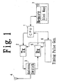
- FIG. 1 is a general block diagram of the TDMA communications apparatus according to the embodiment of the invention.
- a transmitter section 2 converts transmit data edited for own station by a central processing unit (CPU) 1 into a radio frequency (RF) transmit signal and outputs the RF transmit signal in accordance with a timing signal generated by a timing pulse generator 6.
- CPU central processing unit
- RF radio frequency
- the transmitter section 2 receives binary bit data from the CPU 1 with specific timing as will be later discussed, modulates a carrier containing binary bit data information by using a Gaussian Minimum Shift Keying Frequency Modulation (GMSK/FM) coding scheme, and amplifies and outputs a GMSK/FM-modulated signal to an antenna switch 3.
- the binary bit data is message data structured in accordance with a predefined format containing a body text of message including Maritime Mobile Service Identity (MMSI, or station number) and position information, a transmit slot number and next transmission allocation information.
- the next transmission allocation information includes message data indicating a protocol, such as SOTDMA or Incremental Time Division Multiple Access (ITDMA), and information according to the respective protocols.
- the antenna switch 3 Controlled by a transmit/receive switching signal fed from the CPU 1, the antenna switch 3 outputs the RF transmit signal delivered from the transmitter section 2 to an antenna 4 in a transmit slot and outputs an RF receive signal containing transmit data received by the antenna 4 from another participating station (other stations) to a receiver section 5.
- the antenna 4 transmits the RF transmit signal and receives the incoming RF receive signal.
- the receiver section 5 demodulates and decodes the RF receive signal received by the antenna 4 and fed through the antenna switch 3 to acquire the transmit data sent from the other stations and delivers the transmit data to the CPU 1.
- the CPU 1 outputs a timing control signal to be used for slot synchronization to the timing pulse generator 6 in accordance with a timing signal, such as a one pulse-per-second (LPPS) signal fed from a global positioning system (GPS) receiver (not shown).
- a timing signal such as a one pulse-per-second (LPPS) signal fed from a global positioning system (GPS) receiver (not shown).
- the CPU 1 also analyzes the transmit data of the other stations fed from the receiver section 5 and, upon acquiring transmit data from a newly set reference station, performs frame synchronization by adjusting the own station's slot number in accordance with the reference station's slot number.
- the CPU 1 acquires from the transmit data of the other participating stations fed from the receiver section 5 a message and transmit slot allocation information sent from each of the other participating stations and writes the transmit slot allocation information thus acquired in a slot map 70 within a memory 7. Additionally, the CPU 1 configures transmit slot allocation information including a slot number specifying a transmit slot to be pre-reserved for future transmissions by the own station and a new time-out value (an initial time-out value in a case where a slot number is to be newly set) by a later-described procedure and edits transmit data of the own station containing the transmit slot allocation information and other pieces of information to be included in the own station's transmit message. The CPU 1 outputs this transmit data to the transmitter section 2 with proper timing for a predetermined transmit slot.
- An integer defining the aforementioned initial time-out value is randomly selected from a range of "3" to "7" when a station sets (transmits) a slot number specifying a transmit slot to be pre-reserved for future transmissions. Then, priority is given to that station to use the pre-reserved transmit slot designated by the slot number for a period of as many successive frames as specified by the initial time-out value.
- the time-out value begins from the initial time-out value and is successively decremented by 1 from one frame to the next, or each time the TDMA communications apparatus transmits the RF transmit signal (transmit data). When the TDMA communications apparatus transmits the next time after the time-out value has reached "0", the TDMA communications apparatus sets a new slot number specifying a transmit slot to be pre-reserved for future transmissions and a new time-out value.
- the TDMA communications apparatus allocates for its own next transmission a transmit slot of the same slot number in a next frame as already pre-reserved.
- the TDMA communications apparatus sets a new slot number specifying a transmit slot to be pre-reserved for future transmissions together with a new time-out value specifying a particular number of succeeding frames which is predetermined within a specific period, or a Selection Interval (SI), in such a way that the slot number of the pre-reserved transmit slot will not conflict with those slot numbers which have been known to be already pre-reserved by other stations upon analyzing messages received from the other stations.
- SI Selection Interval
- the CPU 1 When setting a new slot number specifying a transmit slot to be pre-reserved for future transmissions, the CPU 1 examines whether transmit slots adjacent to the transmit slot to be pre-reserved for own use are pre-reserved by any of the other stations based on the transmit slot allocation information stored in the slot map 70 of the memory 7. If either of the transmit slots adjacent to the transmit slot to be pre-reserved for own use is pre-reserved by any of the other stations, the CPU 1 finds out the time-out value set for each such transmit slot pre-reserved by another station.
- the CPU 1 sets for own future transmissions an initial time-out value different from the time-out value set by any of the other stations by selecting a proper integer from the aforementioned range of "3" to "7".
- This form of transmit slot allocation is hereinafter referred to as conflict-preventing transmit slot allocation scheme.
- the CPU 1 sets a time-out value for future transmissions by the own station by the aforementioned conflict-preventing transmit slot allocation scheme, however, another station may next pre-reserve a transmit slot adjacent to the transmit slot pre-reserved for use by the own station with the same time-out value. Should such a situation occur, the CPU 1 of the own station takes one of the following actions based on the transmit slot allocation information stored in the slot map 70 of the memory 7:
- the CPU 1 performing operations (1) and (2) above corresponds, respectively, to time-out value setting means and transmission stop means of claims appended to the present Specification of the invention.
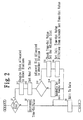
- FIG. 2 is a flowchart showing a conflict-preventing transmit slot allocation procedure
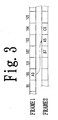
- FIG. 3 is a conceptual diagram of the conflict-preventing transmit slot allocation procedure.
- numerals shown at the top indicates slot numbers of each frame, and alphanumeric symbols written in slots (shown by rectangles) each include a letter indicating a station and a number indicating a time-out value (or an initial time-out value), wherein "A" designates the own station and "B", "C", and so on designate other stations.
- the CPU 1 of the TDMA communications apparatus of the embodiment examines whether a slot to be now allocated for a next transmission is a first slot (step S1).
- the "first slot” means either a slot in which the own station actually transmits for the first time or a slot to be allocated after the time-out value has reached "0" in a preceding frame.
- step S1 If the slot to be now allocated is not the first slot (No in step S1), the CPU 1 decrements the time-out value by 1 from that in the preceding frame (step S2) and generates, or edits, new transmit slot allocation information (step S3). If the slot to be now allocated is the first slot (Yes in step S1), on the other hand, the CPU 1 examines whether there are any slots already allocated for future transmissions by other stations within the Selection Interval SI in a frame in which the next transmission of the own station is to be allocated referring to the transmit slot allocation information stored in the slot map 70 of the memory 7 and finds out a free (or unreserved) slot within the Selection Interval SI (step S11). Then, the CPU 1 allocates the free slot as a next transmit slot of the own station and sets the slot number of the free slot as the slot number of the next transmit slot of the own station (step S12).
- the CPU 1 examines whether a slot adjacent to the next transmit slot of the own station is allocated to any of the other stations (step S13). If neither of the slots adjacent to the next transmit slot of the own station is allocated to any other station, the CPU 1 randomly selects one of integers "3" to "7" and sets the selected integer as the initial time-out value (step S14). Then, the CPU 1 edits transmit data (step S3).
- the CPU 1 examines the time-out value set by that station for the adjacent slot (step S15). Then, the CPU 1 of the TDMA communications apparatus of the own station sets an initial time-out value differing from the time-out value already set by the other station for the adjacent slot (step S16) and edits transmit data (step S3). If both slots adjacent to the next transmit slot of the own station are already allocated to two other stations, the CPU 1 of the own station sets an initial time-out value differing from the time-out values already set by the two other stations for both adjacent slots.
- step S1 the CPU 1 of the TDMA communications apparatus of the own station finds out free slots from among slot Nos. 100 to 105 within the Selection Interval SI in frame 2 (steps S1, S11).
- the CPU 1 selects slot No. 103 as a next transmit slot of the own station from among free slots 100, 101, 103, 105 thus found, for example, (step S12). Subsequently, the CPU 1 detects that slot No.
- step S13, S15 the CPU 1 of the own station sets an initial time-out value "5" differing from the time-out values "7" and "6" already set by stations B and C for the next transmit slot of the own station (step S16). Then, the CPU 1 edits transmit data (step S3) and transmits the same in slot No. 100 in the current frame 1.
- the other stations including stations B and C recognize that slot No. 103 in frame 2 has been allocated to station A for a next transmission by analyzing the transmit data received from station A in slot No. 100 in frame 1.
- the time-out value of the own station becomes "0" in a frame differing from a frame in which the time-out value of either of stations B and C becomes “0".
- the time-out values of multiple stations will not become "0" in successive slots of the same frame.
- This arrangement of the embodiment helps prevent different stations from newly allocating successive slots for future transmissions.
- the arrangement of the embodiment also helps prevent a station which is going to allocate a next transmit slot at a slot immediately succeeding to a transmit slot already allocated to another station from setting a slot number specifying the next transmit slot before recognizing the slot number of the transmit slot already allocated to the latter station. Consequently, the TDMA communications apparatus of the embodiment serves to prevent transmit slot allocation conflicts among multiple stations carrying out the TDMA communication.
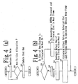
- FIG. 4A is a flowchart showing a procedure for updating the slot map 70 upon receiving transmit data from another station.
- the CPU 1 analyzes transmit slot allocation information contained in the received transmit data (step S21) and judges whether a new transmit slot allocation is included in the transmit slot allocation information (step S22). If a new transmit slot allocation is included is included, the CPU 1 updates the slot map 70 in the memory 7 by writing a slot number specifying a transmit slot to be allocated to that station (step S23).
- the CPU 1 detects that a new transmit slot has been allocated by another station with the same time-out value as the own station at a slot adjacent to the next transmit slot of the own station at this point, the CPU 1 of the own station resets the time-out value to "0" and newly allocates a next transmit slot.
- the CPU 1 of the own station If the time-out value set for neither of slots preceding and succeeding to the next transmit slot of the own station allocated is "0", the CPU 1 of the own station newly allocates a next transmit slot as discussed above. If the time-out value set by another station for one of the slots preceding and succeeding to the next transmit slot of the own station allocated is "0" and the time-out value set by the own station is not "0", however, the CPU 1 of the own station does not immediately resets the time-out value to "0” but normally decrements the time-out value for one or more frames and resets the time-out value of the own station to "0" upon confirming that neither of the slots preceding and succeeding to the next transmit slot of the own station allocated is "0".
- the own station sets a different time-out value anew by performing the aforementioned operating procedure.
- This arrangement of the embodiment helps prevent such a situation that the time-out value set by the own station and the time-out value set by another station become "0" in succession in two adjacent transmit slots. transmit slot already allocated to the latter station. Consequently, the TDMA communications apparatus of the embodiment serves to prevent transmit slot allocation conflicts among multiple stations in a more reliable fashion.
- FIG. 4B is a flowchart showing the procedure for preventing transmit slot conflicts
- FIG. 5 is a conceptual diagram of the procedure for preventing transmit slot conflicts.
- the CPU 1 of the own station analyzes the received transmit data and, if a new transmit slot allocation is found in the received transmit data, the CPU 1 writes a slot number specifying a transmit slot to be allocated to that station in the slot map 70 stored in the memory 7 (steps S21, S22, S23) as already discussed with reference to FIG. 4A .
- the CPU 1 examines whether a transmit slot of the own station is allocated within a next Selection Interval SI (step S31).
- step S31 If there is a transmit slot of the own station is allocated within a next Selection Interval SI (Yes in step S31), the CPU 1 causes the TDMA communications apparatus of the own station to transmit in the autonomous and continuous mode of the SOTDMA protocol and perform transmit slot allocation operation (step S35).
- step S31 If there is no transmit slot of the own station is allocated within the next Selection Interval SI (No in step S31), or if the CPU 1 finds that a slot which the CPU 1 intended to allocate as a next transmit slot of the own station has just been allocated to another station, the CPU 1 cancels allocation of that slot (step S32).
- the CPU 1 randomly selects one of free slots available within the next Selection Interval SI in which the CPU 1 intended to allocate as a next transmit slot of the own station (step S33) and, then, the CPU 1 calculates an offset value to the selected slot and performs ITDMA transmit operation (step S34).
- the selected slot is reserved anew as the next transmit slot of the own station.
- the CPU 1 can reserve the same slot in the next frame as in SOTDMA communication by maintaining a frame keep flag in an ON state (step S34).
- the TDMA communications apparatus of the embodiment prevents transmit slot allocation conflicts by canceling transmission in a slot of the own station once allocated according to the above-described operating procedure when a conflict with a next transmit slot of another station is expected to occur. Furthermore, the TDMA communications apparatus of the embodiment can prevent the transmit slot allocation conflict by re-allocating a free slot within the same Selection Interval SI as the next transmit slot of the own station without changing the report rate.
- the invention is also applicable to a TDMA communications apparatus which edits a transmit message in a slot other than the slot immediately preceding the allocated transmit slot of the own station.
- the CPU of the TDMA communications apparatus does not provide a sufficiently high throughput, the CPU can not edit a transmit message in a timely fashion within a slot immediately preceding an allocated transmit slot of the own station.
Landscapes
- Engineering & Computer Science (AREA)
- Computer Networks & Wireless Communication (AREA)
- Signal Processing (AREA)
- Mobile Radio Communication Systems (AREA)
- Time-Division Multiplex Systems (AREA)
Claims (3)
- TDMA-Kommunikationsvorrichtung zum Ausführen der Kommunikation mit einem oder mehreren anderen solchen Vorrichtungen mit Hilfe der TDMA-Technologie, bei welcher ein Bildfeld gemäß einem vorgeschriebenen Zeitteilungssystem in mehrere Steckplätze geteilt ist, wobei die Vorrichtung in den gleichen Steckplatz übertragen werden kann, der wie in vielen aufeinander folgenden Bildfeldern nach der Spezifizierung durch einen Zeitbegrenzungswert zugeordnet wird, der von einem Bildfeld zum nächsten um 1 inkrementiert wird, wobei die Vorrichtung ein Verarbeitungsmittel (1) zum Reservieren eines neuen Steckplatzes für zukünftige Übertragungen zusammen mit einem anfänglichen Zeitbegrenzungswert zu einem Zeitpunkt umfasst, an dem ein vorher eingestellter Zeitbegrenzungswert einen speziellen Wert erreicht, dadurch gekennzeichnet, dass das Verarbeitungsmittel (1) einen von einer anderen Vorrichtung eingestellten Zeitbegrenzungswert für jeden der Steckplätze detektieren kann, der dem durch die eine Vorrichtung zuzuordnenden Steckplatz benachbart ist und den anfänglichen Zeitbegrenzungswert auf einen Wert einstellen kann, der sich von dem detektierten Zeitbegrenzungswert der anderen Vorrichtung für den Steckplatz der Vorrichtung unterscheidet, der zu einem Zeitpunkt zuzuordnen ist, an welchem sich die eine Vorrichtung den neuen Steckplatz reserviert.
- TDMA-Kommunikationsvorrichtung nach Anspruch 1, wobei das Verarbeitungsmittel die Übertragung in den neu reservierten Steckplatz annullieren kann, wenn sie detektiert, dass der von der anderen Vorrichtung eingestellte Zeitbegrenzungswert für einen Steckplatz, der dem zuzuordnenden Steckplatz der einen Vorrichtung benachbart ist, einen speziellen Wert in einem Steckplatz erreicht hat, in welchem der Zeitbegrenzungswert für die eine Vorrichtung ebenfalls einen speziellen Wert erreicht hat, und außerdem in einem nachfolgenden Steckplatz detektieren kann, dass der durch die eine Vorrichtung für zukünftige Übertragungen neu reservierte Steckplatz mit einem von der anderen Vorrichtung neu reservierten Steckplatz übereinstimmt, dessen Zeitbegrenzungswert den gleichen speziellen Wert erreicht hat.
- TDMA-Kommunikationsvorrichtung nach Anspruch 1 oder 2, den wobei das Verarbeitungsmittel den Zeitbegrenzungswert der einen Vorrichtung auf den speziellen Wert umstellen kann, wenn sie detektiert, dass der für die eine Vorrichtung neu reservierte Steckplatz mit dem Zeitbegrenzungswert übereinstimmt, welchen die andere Vorrichtung für einen neu reservierten Steckplatz eingestellt hat, der dem zuzuordnenden Steckplatz der einen Vorrichtung benachbart ist.
Applications Claiming Priority (1)
| Application Number | Priority Date | Filing Date | Title |
|---|---|---|---|
| JP2004342860A JP4486483B2 (ja) | 2004-11-26 | 2004-11-26 | Tdma通信装置 |
Publications (2)
| Publication Number | Publication Date |
|---|---|
| EP1662678A1 EP1662678A1 (de) | 2006-05-31 |
| EP1662678B1 true EP1662678B1 (de) | 2008-04-02 |
Family
ID=35677476
Family Applications (1)
| Application Number | Title | Priority Date | Filing Date |
|---|---|---|---|
| EP05257258A Ceased EP1662678B1 (de) | 2004-11-26 | 2005-11-25 | TDMA-Kommunikationsvorrichtung |
Country Status (4)
| Country | Link |
|---|---|
| US (1) | US7620022B2 (de) |
| EP (1) | EP1662678B1 (de) |
| JP (1) | JP4486483B2 (de) |
| DE (1) | DE602005005767T2 (de) |
Families Citing this family (20)
| Publication number | Priority date | Publication date | Assignee | Title |
|---|---|---|---|---|
| JP4762067B2 (ja) * | 2006-07-11 | 2011-08-31 | 富士通株式会社 | 移動体通信装置及びプログラム |
| WO2008023638A1 (en) * | 2006-08-21 | 2008-02-28 | Panasonic Corporation | Wireless communication system, communication control method and communication node |
| CA2680118A1 (en) * | 2007-03-16 | 2008-09-25 | Nigel Waites | Improved boot in a media player with external memory |
| DE202007005371U1 (de) * | 2007-04-12 | 2008-05-15 | Weatherdock Ag | Gerät zur Aufnahme von AIS-Telegrammen |
| US7876865B2 (en) | 2007-06-08 | 2011-01-25 | COM DEV International Ltd | System and method for decoding automatic identification system signals |
| US20090161797A1 (en) * | 2007-06-08 | 2009-06-25 | Cowles Philip R | Satellite detection of automatic identification system signals |
| JP5259137B2 (ja) * | 2007-08-10 | 2013-08-07 | ヤマハ発動機株式会社 | 接続機器およびプログラム |
| JP5253112B2 (ja) * | 2008-11-28 | 2013-07-31 | 三洋電機株式会社 | 報知方法および無線装置 |
| US8780788B2 (en) | 2009-09-25 | 2014-07-15 | Com Dev International Ltd. | Systems and methods for decoding automatic identification system signals |
| US9331774B2 (en) | 2010-06-09 | 2016-05-03 | Exactearth Ltd. | Systems and methods for segmenting a satellite field of view for detecting radio frequency signals |
| JP5832811B2 (ja) * | 2011-08-05 | 2015-12-16 | 京セラ株式会社 | 無線基地局及び無線通信システム |
| US9015567B2 (en) | 2012-04-12 | 2015-04-21 | Com Dev International Ltd. | Methods and systems for consistency checking and anomaly detection in automatic identification system signal data |
| US9692586B2 (en) * | 2014-04-21 | 2017-06-27 | National Instruments Corporation | Flexible real time scheduler for time division duplexing and/or frequency division duplexing |
| US9867180B2 (en) * | 2015-12-17 | 2018-01-09 | Honeywell International Inc. | Cognitive allocation of TDMA resources in the presence of a radio altimeter |
| US10177868B2 (en) | 2015-12-17 | 2019-01-08 | Honeywell International Inc. | Systems and methods to synchronize wireless devices in the presence of a FMCW radio altimeter |
| US10725170B2 (en) | 2015-12-17 | 2020-07-28 | Honeywell International Inc. | Frequency modulated continuous wave radio altimeter spectral monitoring |
| DK3226609T3 (da) * | 2016-04-01 | 2019-09-02 | Ericsson Telefon Ab L M | Fremgangsmåde til scheduling af køretøj-til-køretøj-kommunikationer |
| CN109478939B (zh) * | 2016-07-29 | 2021-02-12 | 古野电气株式会社 | Tdma通信装置、tdma通信方法 |
| US10299266B2 (en) | 2017-03-20 | 2019-05-21 | Honeywell International Inc. | Delay calculation in wireless systems |
| CN115802472A (zh) * | 2021-09-10 | 2023-03-14 | 中兴通讯股份有限公司 | 信元流的发送方法、装置、网络设备和存储介质 |
Family Cites Families (19)
| Publication number | Priority date | Publication date | Assignee | Title |
|---|---|---|---|---|
| US4891805A (en) * | 1988-06-13 | 1990-01-02 | Racal Data Communications Inc. | Multiplexer with dynamic bandwidth allocation |
| US5187707A (en) * | 1990-12-03 | 1993-02-16 | Northern Telecom Limited | Packet data flow control for an isdn D-channel |
| US5594727A (en) * | 1994-09-19 | 1997-01-14 | Summa Four, Inc. | Telephone switch providing dynamic allocation of time division multiplex resources |
| US5719868A (en) * | 1995-10-05 | 1998-02-17 | Rockwell International | Dynamic distributed, multi-channel time division multiple access slot assignment method for a network of nodes |
| US6026485A (en) * | 1996-01-24 | 2000-02-15 | Sun Microsystems, Inc. | Instruction folding for a stack-based machine |
| US5673253A (en) * | 1996-02-29 | 1997-09-30 | Siemens Business Communication Systems | Dynamic allocation of telecommunications resources |
| US5987523A (en) * | 1997-06-04 | 1999-11-16 | International Business Machines Corporation | Applet redirection for controlled access to non-orginating hosts |
| US6459681B1 (en) * | 1998-11-13 | 2002-10-01 | Sprint Communications Company L.P. | Method and system for connection admission control |
| US7006530B2 (en) * | 2000-12-22 | 2006-02-28 | Wi-Lan, Inc. | Method and system for adaptively obtaining bandwidth allocation requests |
| US6665301B1 (en) * | 1999-06-03 | 2003-12-16 | Fujitsu Network Communications, Inc. | Transmission slot allocation method and map for virtual tunnels in a transmission line |
| AU6615600A (en) * | 1999-07-29 | 2001-02-19 | Foxboro Company, The | Methods and apparatus for object-based process control |
| US20030149986A1 (en) * | 1999-08-10 | 2003-08-07 | Mayfield William W. | Security system for defeating satellite television piracy |
| US6944148B1 (en) * | 1999-09-10 | 2005-09-13 | Pulse-Link, Inc. | Apparatus and method for managing variable-sized data slots within a time division multiple access frame |
| EP1290529B1 (de) * | 2000-05-15 | 2006-03-01 | Konstantinos Amouris | Verfahren zum dynamischen zuteilen von zeitschlitzen eines gemeinsamen tdma-rundsendekanals zu einem netzwerk von sender/empfaengerknoten |
| JP2003057579A (ja) | 2001-08-17 | 2003-02-26 | Ricoh Co Ltd | レーザ光源装置とそれを搭載した画像形成装置 |
| KR100439186B1 (ko) * | 2001-12-28 | 2004-07-05 | 한국전자통신연구원 | 자바 가상머신의 멀티 쓰레드 시스템에서의 동기화 장치및 방법 |
| JP4014517B2 (ja) * | 2003-03-04 | 2007-11-28 | 古野電気株式会社 | Tdma通信装置 |
| US20040216096A1 (en) * | 2003-04-28 | 2004-10-28 | Alan Messer | Partitioning of structured programs |
| US7516459B2 (en) * | 2004-02-20 | 2009-04-07 | Intel Corporation | Methods and apparatus to optimize managed application program interfaces |
-
2004
- 2004-11-26 JP JP2004342860A patent/JP4486483B2/ja not_active Expired - Fee Related
-
2005
- 2005-11-25 EP EP05257258A patent/EP1662678B1/de not_active Ceased
- 2005-11-25 DE DE602005005767T patent/DE602005005767T2/de not_active Expired - Lifetime
- 2005-11-28 US US11/287,401 patent/US7620022B2/en active Active
Also Published As
| Publication number | Publication date |
|---|---|
| US20060114862A1 (en) | 2006-06-01 |
| DE602005005767T2 (de) | 2009-05-07 |
| US7620022B2 (en) | 2009-11-17 |
| EP1662678A1 (de) | 2006-05-31 |
| JP4486483B2 (ja) | 2010-06-23 |
| DE602005005767D1 (de) | 2008-05-15 |
| JP2006157291A (ja) | 2006-06-15 |
Similar Documents
| Publication | Publication Date | Title |
|---|---|---|
| US7620022B2 (en) | TDMA communications apparatus | |
| US7957755B2 (en) | Mobile station, radio access network apparatus, mobile communication system and broadcast information transmitting and receiving method | |
| AU669038B2 (en) | Method of measuring adjacent base stations in TDMA radio system and TDMA radio system | |
| US20080107095A1 (en) | Method and apparatus for a communication system operating in a licensed rf and an unlicensed rf band | |
| US5586122A (en) | Time division multiple access mobile wireless telecommunication system | |
| US7561591B2 (en) | TDMA communications apparatus | |
| US20140105193A1 (en) | Methods and arrangements in a radio communication system | |
| JP2004312728A (ja) | 多元接続通信システム | |
| US7852904B2 (en) | Method and apparatus for reducing data collisions in a frequency hopping communication system | |
| EP1266534B1 (de) | Spreizspektrumkommunikationssystem mit frequenzspringen | |
| EP1695583B1 (de) | Verfahren und vorrichtung zur bestimmung des inhalts von einer basisstation zu sendenden bursts | |
| EP2341749B1 (de) | Funkkommunikationssystem, funkkommunikationsverfahren, funkkommunikationsendgerät, relaisvorrichtung und relaissystem | |
| US20060206601A1 (en) | Method of designating a future network coordinator | |
| US20120195293A1 (en) | Method, and associated apparatus, for communicating data at reduced transmission latency in radio communication system having slotted interface | |
| EP3379860B1 (de) | Relaisvorrichtung und relaissystem | |
| CN102308658A (zh) | 共享的上行链路通知突发(sunb) | |
| EP3226609A1 (de) | Verfahren zur planung von kommunikation von fahrzeug zu fahrzeug | |
| WO2021051328A1 (zh) | 信息发送、接收方法、装置、设备及存储介质 | |
| US20060068819A1 (en) | Radio base station system, channel assignment method and channel assignment program | |
| KR101490138B1 (ko) | 듀얼―비콘 무선 네트워크들에서 동기화 방법 및 시스템 | |
| JP2003158764A (ja) | 無線通信システム | |
| US20080198837A1 (en) | System and method for transmitting and receiving signal in communication system | |
| JP2000032530A (ja) | デジタル移動通信ランダムアクセス制御方法 | |
| CN121510083A (zh) | 信息传输方法、装置、电子设备及计算机可读存储介质 | |
| EP1816886B1 (de) | Kommunikation von Daten mit verringerter Übertragungslatenzzeit in einem Funkkommunikationssystem mit TDMA Radioschnittstelle |
Legal Events
| Date | Code | Title | Description |
|---|---|---|---|
| PUAI | Public reference made under article 153(3) epc to a published international application that has entered the european phase |
Free format text: ORIGINAL CODE: 0009012 |
|
| AK | Designated contracting states |
Kind code of ref document: A1 Designated state(s): AT BE BG CH CY CZ DE DK EE ES FI FR GB GR HU IE IS IT LI LT LU LV MC NL PL PT RO SE SI SK TR |
|
| AX | Request for extension of the european patent |
Extension state: AL BA HR MK YU |
|
| 17P | Request for examination filed |
Effective date: 20061025 |
|
| 17Q | First examination report despatched |
Effective date: 20061227 |
|
| AKX | Designation fees paid |
Designated state(s): DE GB |
|
| GRAP | Despatch of communication of intention to grant a patent |
Free format text: ORIGINAL CODE: EPIDOSNIGR1 |
|
| GRAS | Grant fee paid |
Free format text: ORIGINAL CODE: EPIDOSNIGR3 |
|
| GRAA | (expected) grant |
Free format text: ORIGINAL CODE: 0009210 |
|
| AK | Designated contracting states |
Kind code of ref document: B1 Designated state(s): DE GB |
|
| REG | Reference to a national code |
Ref country code: GB Ref legal event code: FG4D |
|
| REF | Corresponds to: |
Ref document number: 602005005767 Country of ref document: DE Date of ref document: 20080515 Kind code of ref document: P |
|
| PLBE | No opposition filed within time limit |
Free format text: ORIGINAL CODE: 0009261 |
|
| STAA | Information on the status of an ep patent application or granted ep patent |
Free format text: STATUS: NO OPPOSITION FILED WITHIN TIME LIMIT |
|
| 26N | No opposition filed |
Effective date: 20090106 |
|
| PGFP | Annual fee paid to national office [announced via postgrant information from national office to epo] |
Ref country code: GB Payment date: 20231006 Year of fee payment: 19 |
|
| PGFP | Annual fee paid to national office [announced via postgrant information from national office to epo] |
Ref country code: DE Payment date: 20230929 Year of fee payment: 19 |
|
| P01 | Opt-out of the competence of the unified patent court (upc) registered |
Free format text: CASE NUMBER: UPC_APP_325039/2023 Effective date: 20230523 |
|
| REG | Reference to a national code |
Ref country code: DE Ref legal event code: R119 Ref document number: 602005005767 Country of ref document: DE |
|
| GBPC | Gb: european patent ceased through non-payment of renewal fee |
Effective date: 20241125 |
|
| PG25 | Lapsed in a contracting state [announced via postgrant information from national office to epo] |
Ref country code: DE Free format text: LAPSE BECAUSE OF NON-PAYMENT OF DUE FEES Effective date: 20250603 |
|
| PG25 | Lapsed in a contracting state [announced via postgrant information from national office to epo] |
Ref country code: GB Free format text: LAPSE BECAUSE OF NON-PAYMENT OF DUE FEES Effective date: 20241125 |