EP1662533A1 - Elément détachable fixé sur un disjoncteur - Google Patents
Elément détachable fixé sur un disjoncteur Download PDFInfo
- Publication number
- EP1662533A1 EP1662533A1 EP04405730A EP04405730A EP1662533A1 EP 1662533 A1 EP1662533 A1 EP 1662533A1 EP 04405730 A EP04405730 A EP 04405730A EP 04405730 A EP04405730 A EP 04405730A EP 1662533 A1 EP1662533 A1 EP 1662533A1
- Authority
- EP
- European Patent Office
- Prior art keywords
- housing
- lever
- component
- component according
- hook
- Prior art date
- Legal status (The legal status is an assumption and is not a legal conclusion. Google has not performed a legal analysis and makes no representation as to the accuracy of the status listed.)
- Granted
Links
- 230000001681 protective effect Effects 0.000 claims abstract description 36
- 230000007935 neutral effect Effects 0.000 claims description 8
- 238000003780 insertion Methods 0.000 claims description 2
- 230000037431 insertion Effects 0.000 claims description 2
- 239000004020 conductor Substances 0.000 description 5
- 238000005304 joining Methods 0.000 description 5
- 238000001746 injection moulding Methods 0.000 description 4
- 125000000524 functional group Chemical group 0.000 description 3
- 238000009434 installation Methods 0.000 description 2
- 230000010354 integration Effects 0.000 description 2
- 238000004519 manufacturing process Methods 0.000 description 2
- 239000000463 material Substances 0.000 description 2
- 238000000034 method Methods 0.000 description 2
- 239000003795 chemical substances by application Substances 0.000 description 1
- 238000009826 distribution Methods 0.000 description 1
- 230000000694 effects Effects 0.000 description 1
- 238000005516 engineering process Methods 0.000 description 1
- 239000011810 insulating material Substances 0.000 description 1
- 238000003825 pressing Methods 0.000 description 1
Images


Classifications
-
- H—ELECTRICITY
- H01—ELECTRIC ELEMENTS
- H01H—ELECTRIC SWITCHES; RELAYS; SELECTORS; EMERGENCY PROTECTIVE DEVICES
- H01H71/00—Details of the protective switches or relays covered by groups H01H73/00 - H01H83/00
- H01H71/02—Housings; Casings; Bases; Mountings
- H01H71/0264—Mountings or coverplates for complete assembled circuit breakers, e.g. snap mounting in panel
- H01H71/0271—Mounting several complete assembled circuit breakers together
-
- H—ELECTRICITY
- H01—ELECTRIC ELEMENTS
- H01H—ELECTRIC SWITCHES; RELAYS; SELECTORS; EMERGENCY PROTECTIVE DEVICES
- H01H71/00—Details of the protective switches or relays covered by groups H01H73/00 - H01H83/00
- H01H71/02—Housings; Casings; Bases; Mountings
- H01H71/0207—Mounting or assembling the different parts of the circuit breaker
- H01H2071/0242—Assembling parts of a circuit breaker by using snap mounting techniques
-
- H—ELECTRICITY
- H01—ELECTRIC ELEMENTS
- H01H—ELECTRIC SWITCHES; RELAYS; SELECTORS; EMERGENCY PROTECTIVE DEVICES
- H01H71/00—Details of the protective switches or relays covered by groups H01H73/00 - H01H83/00
- H01H71/002—Details of the protective switches or relays covered by groups H01H73/00 - H01H83/00 with provision for switching the neutral conductor
-
- H—ELECTRICITY
- H01—ELECTRIC ELEMENTS
- H01H—ELECTRIC SWITCHES; RELAYS; SELECTORS; EMERGENCY PROTECTIVE DEVICES
- H01H71/00—Details of the protective switches or relays covered by groups H01H73/00 - H01H83/00
- H01H71/10—Operating or release mechanisms
- H01H71/12—Automatic release mechanisms with or without manual release
- H01H71/46—Automatic release mechanisms with or without manual release having means for operating auxiliary contacts additional to the main contacts
- H01H71/462—Automatic release mechanisms with or without manual release having means for operating auxiliary contacts additional to the main contacts housed in a separate casing, juxtaposed to and having the same general contour as the main casing
Definitions
- the present invention relates to a component for releasably attaching to an electrical protective device according to the preamble of claim 1.
- the coupled with such a component protective device is preferably used in low-voltage distributors on the basis of a mounting rail or a socket with parallel guided and held on the socket busbars.
- the installation circuit breakers are designed as circuit breakers.
- the live components and systems are therefore protected against the consequences of overload and short-circuit currents.
- Protective devices designed as surge arresters protect the components and systems against overvoltage.
- Components with specific functional groups can be detachably fastened to the protective devices, which can be installed together with the protective device in the low-voltage distributor or removed from the distributor.
- a built-in part of the type mentioned above is described in the technical catalog smiss-line S "Innovation with System - Protection devices with plug-in technology" from. ABB Switzerland AG, Normelec / CMC Components PO Box CH-9048 Zurich / Switzerland.
- the known installation part has a box-shaped housing for receiving a functional group.
- a preferred fitting is a Neutral conductor separator or a contact block with auxiliary or with signal contacts, which are each assigned to a designed as a switch protection device.
- the previously known component has at the corners of one side of a substantially box-shaped component housing four each formed as snap hooks connecting elements.
- two of these snap hooks are snapped into two corresponding recesses of the protective device and the component pivoted slightly in the manner of a hinge until it rests with its hook-carrying side of the housing on the device.
- the remaining two snap hooks snap into two corresponding recesses on the protection device and thus secure the component to the protection device.
- two of the snap-in connections must be opened simultaneously. This is relatively expensive. Depending on the manual dexterity of the installer, damage to one of these connections can not be ruled out.
- the object is to provide a component of the type mentioned above, which can be attached in a simple and rapid manner to a protective device and conveniently released again when needed from the device.
- a snap element is provided with a biasing force acted upon two-armed lever, the first arm carries a lockable on the protective device hook and the second arm carries a finger grip.
- the lever is first pivoted in a predetermined direction during assembly of the component and protective device and thereby loaded with biasing force.
- the biasing force causes a pivoting of the lever in the opposite direction.
- This snaps the hook to form a positive connection in a recess of the protection device. Due to the positive connection of the snap connection thus formed, the component is securely fixed to the protection device. If necessary, the component can be easily removed from the protection device by actuating the finger grip be solved. In this operation, a biasing force is generated in the lever, which quickly and easily repeals the positive connection of the snap connection. The component can now be easily removed from the protection device.
- the desired biasing force is generally achieved with a spring.
- a pivot axis is guided through the pivot point of the two-armed lever, which contains at least one torsion bar attached to the housing and the lever. Since the pivot axis includes a torsion bar, the desired biasing force can be generated by twisting the torsion bar. An additional spring otherwise required for generating the biasing force can therefore be saved.
- the pivot axis comprises two torsion bars, which together with the lever are an integral part of the housing.
- the housing is generally formed of a polymeric material, then the snap element together with a part of the housing can be made in one piece in a suitable method for mass production, for example by injection molding.
- a secure and against the action of unwanted external forces protected integration of the snap element into the housing is achieved when the finger grip is mounted in an opening of the housing.
- the diameter of the housing opening may be smaller than the diameter of a finger, since the finger grip can thus only be pressed into the housing via a defined path when actuated.
- Overstretching of the snap element is avoided by serving as a stop for the finger boundary of the opening.
- a good access to the finger grip and thus a convenient assembly and disassembly are ensured when the housing opening arranged on a side facing away from the support side of the housing and the two-armed lever is designed as an angle lever.
- a fixedly arranged and designed as a hook connecting element is provided on the support side. With only two fasteners a good attachment is already achieved when the provided on the lever Hook and the fixed arranged hook on the support side facing each other diagonally.
- a constructive unit containing the component according to the invention and the protective device fixedly connected therewith can have as a protective device a switch which is intended to be plugged into a low-voltage distributor, in particular with a busbar-supporting plug-in socket or with a mounting rail.
- the component is then designed as a neutral conductor separator or as a contact block for receiving auxiliary or signal contacts of the switch.
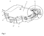
- FIGS. 1 to 6 show a structural unit 1 which has been formed by assembling a protective device 2 designed as a circuit breaker and a component 3 designed as a neutral conductor separator. This unit is intended for insertion into a low-voltage distributor, in particular on the basis of a plug-in base system or a mounting rail.
- the component 3 has a substantially box-shaped housing 4 made of a polymeric insulating material.
- the housing 4 contains interconnected parts, one of which rests on the protective device 2 as the lower part 4 'and the other is a freely accessible upper part 4.
- the housing 4 accommodates the active part that can be connected to a neutral conductor of the distributor and not visible in the figures of neutral neutralizer.
- the component 3 can also be designed as a contact block.
- the correspondingly formed housing 4 then takes on instead of the neutral conductor active auxiliary or signal contacts of the then executed as a switch protection device 2.
- the housing 4 can also accommodate a different functional group.
- the component 3 next to the housing 4 and enclosed by the housing and therefore not apparent function group contains two on the housing 4 held connecting elements 5 and 6 (Fig. 2), with which it is detachably connected to the protective device 2.
- the two connecting elements 5, 6 are guided to a side 7 of the housing 4 formed by the lower part 4 ', which serves to support the protective device 2 (FIGS. 3 and 4).
- the connecting element 5 is formed as a hook and fixedly disposed on the edge of the housing lower part 4 'on the housing side.
- the connecting element 6 is designed as a snap element and has a two-armed lever 8, the first arm carries a lockable on the protective device 2 hook 9 and the second arm carries a finger grip 10.
- the component 3 is hooked with the hook 5 on a recess 18 of the protective device 5 ( Figure 3) and positively applied by pivoting with the housing side 7 to the protective device 2.
- the hook 9 is first guided by striking its downwardly facing joining surface 14 at an undercut 15 of the protective device 2 in the counterclockwise direction to the right.
- the lever 9 is pivoted counterclockwise.
- the lever 9 is loaded during pivoting with a clockwise acting biasing force, which causes the hook 9 engages in the further joining operation in the undercut 15.
- the component 3 is now fixed via two connecting elements 5, 6 positively on the protective device 2.
- the two connecting elements namely the hook 5 and the executed as a twistable snap hook lever 9, each other on the housing side 7 diagonally opposite. Due to this positioning of the two connecting elements, the component 3 is held in a particularly stable position on the protective device 2.
- Other fasteners are then dispensable in general.
- retaining pins 19 may be formed in the housing side, which are inserted into corresponding recesses 20 of the protective device 2.
- the lever 8 When snapping the apparent from Fig.2 position of the two-armed lever 8 is reached, in which the finger grip 10 is an opening 16 of the housing 4 practically flush.
- the lever 8 is pivoted by pressing the finger grip 10 in the direction of arrow 17 against the force of the two torsion bars 12, 13 in the apparent from Figure 3 position.
- the finger grip 10 is arranged in the opening 16 of the housing 2 and the diameter of the housing opening 16 is smaller than the diameter of a finger
- the lever 8 can be pivoted only by a small angle, typically in the range between 5 ° and 15 ° become.
- the opening wall 16 limiting housing wall acts like a stop that secures the snap element 6 from overstretching. If necessary, an additional overstretch protection designed as a stop can be provided inside the housing.
- the finger grip 10 is pressed far enough into the housing, the positive locking is released and the component 3 can now be easily removed from the protective device 2, whereby the apparent from Fig.4 state is reached, in which the protective device 2 and the component. 3 completely separated from each other.
- the finger grip 9 is rotated out of the housing opening 15 by a small angular range, which is typically between 1 ° and 5 °.
- the housing opening 16 is located on a side facing away from the housing side 7 of the housing 4.
Landscapes
- Details Of Connecting Devices For Male And Female Coupling (AREA)
- Lock And Its Accessories (AREA)
- Switch Cases, Indication, And Locking (AREA)
- Fixed Capacitors And Capacitor Manufacturing Machines (AREA)
- Cable Accessories (AREA)
- Burglar Alarm Systems (AREA)
Priority Applications (4)
| Application Number | Priority Date | Filing Date | Title |
|---|---|---|---|
| DE502004011911T DE502004011911D1 (de) | 2004-11-24 | 2004-11-24 | Bauteil zum lösbaren Befestigen an einem elektrischen Schutzgerät |
| AT04405730T ATE488856T1 (de) | 2004-11-24 | 2004-11-24 | Bauteil zum lösbaren befestigen an einem elektrischen schutzgerät |
| EP04405730A EP1662533B1 (fr) | 2004-11-24 | 2004-11-24 | Elément détachable fixé sur un disjoncteur |
| ES04405730T ES2356241T3 (es) | 2004-11-24 | 2004-11-24 | Componente para la fijación desprendible en un aparato de protección eléctrica. |
Applications Claiming Priority (1)
| Application Number | Priority Date | Filing Date | Title |
|---|---|---|---|
| EP04405730A EP1662533B1 (fr) | 2004-11-24 | 2004-11-24 | Elément détachable fixé sur un disjoncteur |
Publications (2)
| Publication Number | Publication Date |
|---|---|
| EP1662533A1 true EP1662533A1 (fr) | 2006-05-31 |
| EP1662533B1 EP1662533B1 (fr) | 2010-11-17 |
Family
ID=34932380
Family Applications (1)
| Application Number | Title | Priority Date | Filing Date |
|---|---|---|---|
| EP04405730A Active EP1662533B1 (fr) | 2004-11-24 | 2004-11-24 | Elément détachable fixé sur un disjoncteur |
Country Status (4)
| Country | Link |
|---|---|
| EP (1) | EP1662533B1 (fr) |
| AT (1) | ATE488856T1 (fr) |
| DE (1) | DE502004011911D1 (fr) |
| ES (1) | ES2356241T3 (fr) |
Cited By (6)
| Publication number | Priority date | Publication date | Assignee | Title |
|---|---|---|---|---|
| DE102006023464A1 (de) * | 2006-05-18 | 2007-11-22 | Siemens Ag | Sensorbaugruppe mit einem an einer Wand montierbaren Gehäuse |
| EP2180494A1 (fr) * | 2008-10-27 | 2010-04-28 | General Electric Company | Cale isolante auxiliaire sans outil |
| WO2011091822A1 (fr) * | 2010-01-26 | 2011-08-04 | Abb Ag | Dispositif de commutation d'installation comportant deux moitiés de boîtier encliquetables |
| WO2013064186A1 (fr) * | 2011-11-03 | 2013-05-10 | Abb Ab | Bloc de contact auxiliaire |
| ITRM20130495A1 (it) * | 2013-09-06 | 2015-03-07 | Bticino Spa | Apparecchio elettrico modulare comprendente elementi di accoppiamento per accoppiare detto apparecchio con un ulteriore apparecchio elettrico modulare |
| EP4113567A4 (fr) * | 2020-10-21 | 2023-10-18 | Fuji Electric Fa Components & Systems Co., Ltd. | Unité de contact auxiliaire |
Citations (4)
| Publication number | Priority date | Publication date | Assignee | Title |
|---|---|---|---|---|
| FR2550907A1 (fr) * | 1983-08-17 | 1985-02-22 | Merlin Gerin | Dispositif d'assemblage de modules d'appareillage electrique |
| EP0223622A1 (fr) * | 1985-10-09 | 1987-05-27 | Telemecanique | Dispositif d'assemblage de blocs modulaires d'appareillage électrique |
| EP0375568A1 (fr) | 1988-12-14 | 1990-06-27 | Merlin Gerin | Dispositif d'assemblage modulaire d'un disjoncteur différentiel multipolaire |
| EP0986136A2 (fr) * | 1998-09-08 | 2000-03-15 | GEWISS S.p.A. | Dispositif de liaison de sécurité en particulier pour appareils électriques modulaires |
-
2004
- 2004-11-24 ES ES04405730T patent/ES2356241T3/es active Active
- 2004-11-24 EP EP04405730A patent/EP1662533B1/fr active Active
- 2004-11-24 DE DE502004011911T patent/DE502004011911D1/de active Active
- 2004-11-24 AT AT04405730T patent/ATE488856T1/de not_active IP Right Cessation
Patent Citations (4)
| Publication number | Priority date | Publication date | Assignee | Title |
|---|---|---|---|---|
| FR2550907A1 (fr) * | 1983-08-17 | 1985-02-22 | Merlin Gerin | Dispositif d'assemblage de modules d'appareillage electrique |
| EP0223622A1 (fr) * | 1985-10-09 | 1987-05-27 | Telemecanique | Dispositif d'assemblage de blocs modulaires d'appareillage électrique |
| EP0375568A1 (fr) | 1988-12-14 | 1990-06-27 | Merlin Gerin | Dispositif d'assemblage modulaire d'un disjoncteur différentiel multipolaire |
| EP0986136A2 (fr) * | 1998-09-08 | 2000-03-15 | GEWISS S.p.A. | Dispositif de liaison de sécurité en particulier pour appareils électriques modulaires |
Cited By (14)
| Publication number | Priority date | Publication date | Assignee | Title |
|---|---|---|---|---|
| DE102006023464A1 (de) * | 2006-05-18 | 2007-11-22 | Siemens Ag | Sensorbaugruppe mit einem an einer Wand montierbaren Gehäuse |
| DE102006023464B4 (de) * | 2006-05-18 | 2010-04-15 | Continental Automotive Gmbh | Sensorbaugruppe mit einem an einer Wand montierbaren Gehäuse |
| US8210037B2 (en) | 2006-05-18 | 2012-07-03 | Continental Automotive Gmbh | Sensor module with a housing which may be mounted on a wall |
| EP2180494A1 (fr) * | 2008-10-27 | 2010-04-28 | General Electric Company | Cale isolante auxiliaire sans outil |
| CN101728095A (zh) * | 2008-10-27 | 2010-06-09 | 通用电气公司 | 无需工具的辅助接触块 |
| WO2011091822A1 (fr) * | 2010-01-26 | 2011-08-04 | Abb Ag | Dispositif de commutation d'installation comportant deux moitiés de boîtier encliquetables |
| WO2013064186A1 (fr) * | 2011-11-03 | 2013-05-10 | Abb Ab | Bloc de contact auxiliaire |
| US8921713B2 (en) | 2011-11-03 | 2014-12-30 | Abb Ab | Auxiliary contact block |
| RU2578127C2 (ru) * | 2011-11-03 | 2016-03-20 | Абб Текнолоджи Лтд. | Блок вспомогательных контактов |
| ITRM20130495A1 (it) * | 2013-09-06 | 2015-03-07 | Bticino Spa | Apparecchio elettrico modulare comprendente elementi di accoppiamento per accoppiare detto apparecchio con un ulteriore apparecchio elettrico modulare |
| EP2846345A1 (fr) * | 2013-09-06 | 2015-03-11 | Bticino S.P.A. | Appareil électrique modulaire comprenant des éléments de couplage pour coupler ledit appareil à un autre appareil électrique modulaire |
| CN104427809A (zh) * | 2013-09-06 | 2015-03-18 | 布蒂克诺公司 | 模块化电气设备和包括彼此耦接模块化电气设备的部件组 |
| RU2668286C2 (ru) * | 2013-09-06 | 2018-09-28 | Бтичино С.П.А. | Модульное электрическое устройство, содержащее соединительные элементы для соединения с другим модульным электрическим устройством |
| EP4113567A4 (fr) * | 2020-10-21 | 2023-10-18 | Fuji Electric Fa Components & Systems Co., Ltd. | Unité de contact auxiliaire |
Also Published As
| Publication number | Publication date |
|---|---|
| DE502004011911D1 (de) | 2010-12-30 |
| EP1662533B1 (fr) | 2010-11-17 |
| ATE488856T1 (de) | 2010-12-15 |
| ES2356241T3 (es) | 2011-04-06 |
Similar Documents
| Publication | Publication Date | Title |
|---|---|---|
| EP2018646B1 (fr) | Commutateur, en particulier sectionneur a coupure en charge | |
| EP1701369B1 (fr) | Disjoncteur électromécanique | |
| WO2001069738A1 (fr) | Plaque d'adaptation et systeme pour monter un composant sur un support de montage | |
| EP0436881B1 (fr) | Dérivateur de surtensions | |
| DE19525438A1 (de) | Sammelschienen-Adaptersystem | |
| EP3510676B1 (fr) | Module de protection contre les surtensions pour un connecteur modulaire | |
| DE202021000293U1 (de) | Datenaustauschgerät und Anordnung | |
| DE102007015470A1 (de) | Schnappbefestigung zur Befestigung eines Gehäuses | |
| EP1662533B1 (fr) | Elément détachable fixé sur un disjoncteur | |
| WO2019110414A1 (fr) | Adaptateur pour le montage de composants électrotechniques | |
| DE10003349A1 (de) | Halterungseinrichtung zur Befestigung wenigstens eines elektrischen Schaltgerätes auf einer Hutprofiltragschiene | |
| DE102015014163A1 (de) | Vorrichtung zum thermischen Auslösen, Abtrennen und/oder Signalisieren des Zustandes eines Überspannungsschutzgerätes | |
| EP1638123B1 (fr) | Disjoncteur avec prise de contact déplaçable | |
| DE102006006914B4 (de) | Vorrichtung zur Befestigung eines Steckverbinders auf einem Tragelement | |
| EP1715500B1 (fr) | interrupteur auxiliaire distributeur électrique à basse tension | |
| DE102015111885A1 (de) | Sicherung für Stromverteiler | |
| DE102006060231B4 (de) | Elektrisches/elektronisches Installationsgerät | |
| EP0976310A1 (fr) | Appareil electrique a deux capots de boitier identiques | |
| EP0649192A2 (fr) | Dispositif d'installation électrique avec module supplémentaire | |
| EP1376793B1 (fr) | Adaptateur pour l'installation de blocs de connection dans des dispositifs de distribution électrique | |
| EP2656366B1 (fr) | Câblage étoile-triangle, en particulier pour un circuit de protection sur une plaque de montage | |
| EP1289085A1 (fr) | Module enfichable pour distributeur moyenne tension | |
| EP0123040A2 (fr) | Plaque à bornes pour des appareils électriques ou électroniques, par exemple pour un interrupteur de protection contre la surintensité | |
| DE102015017297B4 (de) | Schmelzsicherung sowie Verbindungsanordnung mit einer solchen Schmelzsicherung | |
| DE19534690B4 (de) | Abgangskasten für Schienenverteiler |
Legal Events
| Date | Code | Title | Description |
|---|---|---|---|
| PUAI | Public reference made under article 153(3) epc to a published international application that has entered the european phase |
Free format text: ORIGINAL CODE: 0009012 |
|
| AK | Designated contracting states |
Kind code of ref document: A1 Designated state(s): AT BE BG CH CY CZ DE DK EE ES FI FR GB GR HU IE IS IT LI LU MC NL PL PT RO SE SI SK TR |
|
| AX | Request for extension of the european patent |
Extension state: AL HR LT LV MK YU |
|
| 17P | Request for examination filed |
Effective date: 20060819 |
|
| AKX | Designation fees paid |
Designated state(s): AT BE BG CH CY CZ DE DK EE ES FI FR GB GR HU IE IS IT LI LU MC NL PL PT RO SE SI SK TR |
|
| 17Q | First examination report despatched |
Effective date: 20080506 |
|
| GRAP | Despatch of communication of intention to grant a patent |
Free format text: ORIGINAL CODE: EPIDOSNIGR1 |
|
| RIN1 | Information on inventor provided before grant (corrected) |
Inventor name: SCHEFFER, KATJA Inventor name: SCHALK, ADELBERT |
|
| GRAS | Grant fee paid |
Free format text: ORIGINAL CODE: EPIDOSNIGR3 |
|
| GRAA | (expected) grant |
Free format text: ORIGINAL CODE: 0009210 |
|
| AK | Designated contracting states |
Kind code of ref document: B1 Designated state(s): AT BE BG CH CY CZ DE DK EE ES FI FR GB GR HU IE IS IT LI LU MC NL PL PT RO SE SI SK TR |
|
| REG | Reference to a national code |
Ref country code: GB Ref legal event code: FG4D Free format text: NOT ENGLISH |
|
| REG | Reference to a national code |
Ref country code: CH Ref legal event code: EP |
|
| REG | Reference to a national code |
Ref country code: IE Ref legal event code: FG4D |
|
| REF | Corresponds to: |
Ref document number: 502004011911 Country of ref document: DE Date of ref document: 20101230 Kind code of ref document: P |
|
| REG | Reference to a national code |
Ref country code: NL Ref legal event code: VDEP Effective date: 20101117 |
|
| REG | Reference to a national code |
Ref country code: ES Ref legal event code: FG2A Ref document number: 2356241 Country of ref document: ES Kind code of ref document: T3 Effective date: 20110406 |
|
| BERE | Be: lapsed |
Owner name: ABB SCHWEIZ A.G. Effective date: 20101130 |
|
| PG25 | Lapsed in a contracting state [announced via postgrant information from national office to epo] |
Ref country code: CY Free format text: LAPSE BECAUSE OF FAILURE TO SUBMIT A TRANSLATION OF THE DESCRIPTION OR TO PAY THE FEE WITHIN THE PRESCRIBED TIME-LIMIT Effective date: 20101117 Ref country code: NL Free format text: LAPSE BECAUSE OF FAILURE TO SUBMIT A TRANSLATION OF THE DESCRIPTION OR TO PAY THE FEE WITHIN THE PRESCRIBED TIME-LIMIT Effective date: 20101117 Ref country code: SI Free format text: LAPSE BECAUSE OF FAILURE TO SUBMIT A TRANSLATION OF THE DESCRIPTION OR TO PAY THE FEE WITHIN THE PRESCRIBED TIME-LIMIT Effective date: 20101117 Ref country code: IS Free format text: LAPSE BECAUSE OF FAILURE TO SUBMIT A TRANSLATION OF THE DESCRIPTION OR TO PAY THE FEE WITHIN THE PRESCRIBED TIME-LIMIT Effective date: 20110317 Ref country code: SE Free format text: LAPSE BECAUSE OF FAILURE TO SUBMIT A TRANSLATION OF THE DESCRIPTION OR TO PAY THE FEE WITHIN THE PRESCRIBED TIME-LIMIT Effective date: 20101117 Ref country code: FI Free format text: LAPSE BECAUSE OF FAILURE TO SUBMIT A TRANSLATION OF THE DESCRIPTION OR TO PAY THE FEE WITHIN THE PRESCRIBED TIME-LIMIT Effective date: 20101117 Ref country code: PT Free format text: LAPSE BECAUSE OF FAILURE TO SUBMIT A TRANSLATION OF THE DESCRIPTION OR TO PAY THE FEE WITHIN THE PRESCRIBED TIME-LIMIT Effective date: 20110317 Ref country code: BG Free format text: LAPSE BECAUSE OF FAILURE TO SUBMIT A TRANSLATION OF THE DESCRIPTION OR TO PAY THE FEE WITHIN THE PRESCRIBED TIME-LIMIT Effective date: 20110217 |
|
| REG | Reference to a national code |
Ref country code: IE Ref legal event code: FD4D |
|
| PG25 | Lapsed in a contracting state [announced via postgrant information from national office to epo] |
Ref country code: MC Free format text: LAPSE BECAUSE OF NON-PAYMENT OF DUE FEES Effective date: 20101130 Ref country code: GR Free format text: LAPSE BECAUSE OF FAILURE TO SUBMIT A TRANSLATION OF THE DESCRIPTION OR TO PAY THE FEE WITHIN THE PRESCRIBED TIME-LIMIT Effective date: 20110218 |
|
| REG | Reference to a national code |
Ref country code: CH Ref legal event code: PL |
|
| PG25 | Lapsed in a contracting state [announced via postgrant information from national office to epo] |
Ref country code: CZ Free format text: LAPSE BECAUSE OF FAILURE TO SUBMIT A TRANSLATION OF THE DESCRIPTION OR TO PAY THE FEE WITHIN THE PRESCRIBED TIME-LIMIT Effective date: 20101117 Ref country code: CH Free format text: LAPSE BECAUSE OF NON-PAYMENT OF DUE FEES Effective date: 20101130 Ref country code: LI Free format text: LAPSE BECAUSE OF NON-PAYMENT OF DUE FEES Effective date: 20101130 Ref country code: IE Free format text: LAPSE BECAUSE OF FAILURE TO SUBMIT A TRANSLATION OF THE DESCRIPTION OR TO PAY THE FEE WITHIN THE PRESCRIBED TIME-LIMIT Effective date: 20101117 Ref country code: EE Free format text: LAPSE BECAUSE OF FAILURE TO SUBMIT A TRANSLATION OF THE DESCRIPTION OR TO PAY THE FEE WITHIN THE PRESCRIBED TIME-LIMIT Effective date: 20101117 |
|
| PG25 | Lapsed in a contracting state [announced via postgrant information from national office to epo] |
Ref country code: PL Free format text: LAPSE BECAUSE OF FAILURE TO SUBMIT A TRANSLATION OF THE DESCRIPTION OR TO PAY THE FEE WITHIN THE PRESCRIBED TIME-LIMIT Effective date: 20101117 Ref country code: RO Free format text: LAPSE BECAUSE OF FAILURE TO SUBMIT A TRANSLATION OF THE DESCRIPTION OR TO PAY THE FEE WITHIN THE PRESCRIBED TIME-LIMIT Effective date: 20101117 Ref country code: DK Free format text: LAPSE BECAUSE OF FAILURE TO SUBMIT A TRANSLATION OF THE DESCRIPTION OR TO PAY THE FEE WITHIN THE PRESCRIBED TIME-LIMIT Effective date: 20101117 Ref country code: BE Free format text: LAPSE BECAUSE OF NON-PAYMENT OF DUE FEES Effective date: 20101130 Ref country code: SK Free format text: LAPSE BECAUSE OF FAILURE TO SUBMIT A TRANSLATION OF THE DESCRIPTION OR TO PAY THE FEE WITHIN THE PRESCRIBED TIME-LIMIT Effective date: 20101117 |
|
| PLBE | No opposition filed within time limit |
Free format text: ORIGINAL CODE: 0009261 |
|
| STAA | Information on the status of an ep patent application or granted ep patent |
Free format text: STATUS: NO OPPOSITION FILED WITHIN TIME LIMIT |
|
| 26N | No opposition filed |
Effective date: 20110818 |
|
| REG | Reference to a national code |
Ref country code: DE Ref legal event code: R097 Ref document number: 502004011911 Country of ref document: DE Effective date: 20110818 |
|
| REG | Reference to a national code |
Ref country code: AT Ref legal event code: MM01 Ref document number: 488856 Country of ref document: AT Kind code of ref document: T Effective date: 20101124 |
|
| PG25 | Lapsed in a contracting state [announced via postgrant information from national office to epo] |
Ref country code: AT Free format text: LAPSE BECAUSE OF NON-PAYMENT OF DUE FEES Effective date: 20101124 |
|
| PG25 | Lapsed in a contracting state [announced via postgrant information from national office to epo] |
Ref country code: LU Free format text: LAPSE BECAUSE OF NON-PAYMENT OF DUE FEES Effective date: 20101124 Ref country code: HU Free format text: LAPSE BECAUSE OF FAILURE TO SUBMIT A TRANSLATION OF THE DESCRIPTION OR TO PAY THE FEE WITHIN THE PRESCRIBED TIME-LIMIT Effective date: 20110518 |
|
| PG25 | Lapsed in a contracting state [announced via postgrant information from national office to epo] |
Ref country code: TR Free format text: LAPSE BECAUSE OF FAILURE TO SUBMIT A TRANSLATION OF THE DESCRIPTION OR TO PAY THE FEE WITHIN THE PRESCRIBED TIME-LIMIT Effective date: 20101117 |
|
| PGFP | Annual fee paid to national office [announced via postgrant information from national office to epo] |
Ref country code: ES Payment date: 20141126 Year of fee payment: 11 Ref country code: GB Payment date: 20141119 Year of fee payment: 11 |
|
| REG | Reference to a national code |
Ref country code: FR Ref legal event code: PLFP Year of fee payment: 12 |
|
| GBPC | Gb: european patent ceased through non-payment of renewal fee |
Effective date: 20151124 |
|
| PG25 | Lapsed in a contracting state [announced via postgrant information from national office to epo] |
Ref country code: GB Free format text: LAPSE BECAUSE OF NON-PAYMENT OF DUE FEES Effective date: 20151124 |
|
| REG | Reference to a national code |
Ref country code: FR Ref legal event code: PLFP Year of fee payment: 13 |
|
| REG | Reference to a national code |
Ref country code: ES Ref legal event code: FD2A Effective date: 20161230 |
|
| PG25 | Lapsed in a contracting state [announced via postgrant information from national office to epo] |
Ref country code: ES Free format text: LAPSE BECAUSE OF NON-PAYMENT OF DUE FEES Effective date: 20151125 |
|
| REG | Reference to a national code |
Ref country code: FR Ref legal event code: PLFP Year of fee payment: 14 |
|
| PGFP | Annual fee paid to national office [announced via postgrant information from national office to epo] |
Ref country code: FR Payment date: 20181123 Year of fee payment: 15 Ref country code: IT Payment date: 20181126 Year of fee payment: 15 |
|
| PG25 | Lapsed in a contracting state [announced via postgrant information from national office to epo] |
Ref country code: FR Free format text: LAPSE BECAUSE OF NON-PAYMENT OF DUE FEES Effective date: 20191130 Ref country code: IT Free format text: LAPSE BECAUSE OF NON-PAYMENT OF DUE FEES Effective date: 20191124 |
|
| PGFP | Annual fee paid to national office [announced via postgrant information from national office to epo] |
Ref country code: DE Payment date: 20231121 Year of fee payment: 20 |