EP1662533A1 - Removably fixed component on a circuit breaker - Google Patents
Removably fixed component on a circuit breaker Download PDFInfo
- Publication number
- EP1662533A1 EP1662533A1 EP04405730A EP04405730A EP1662533A1 EP 1662533 A1 EP1662533 A1 EP 1662533A1 EP 04405730 A EP04405730 A EP 04405730A EP 04405730 A EP04405730 A EP 04405730A EP 1662533 A1 EP1662533 A1 EP 1662533A1
- Authority
- EP
- European Patent Office
- Prior art keywords
- housing
- lever
- component
- component according
- hook
- Prior art date
- Legal status (The legal status is an assumption and is not a legal conclusion. Google has not performed a legal analysis and makes no representation as to the accuracy of the status listed.)
- Granted
Links
- 230000001681 protective effect Effects 0.000 claims abstract description 36
- 230000007935 neutral effect Effects 0.000 claims description 8
- 238000003780 insertion Methods 0.000 claims description 2
- 230000037431 insertion Effects 0.000 claims description 2
- 239000004020 conductor Substances 0.000 description 5
- 238000005304 joining Methods 0.000 description 5
- 238000001746 injection moulding Methods 0.000 description 4
- 125000000524 functional group Chemical group 0.000 description 3
- 238000009434 installation Methods 0.000 description 2
- 230000010354 integration Effects 0.000 description 2
- 238000004519 manufacturing process Methods 0.000 description 2
- 239000000463 material Substances 0.000 description 2
- 238000000034 method Methods 0.000 description 2
- 239000003795 chemical substances by application Substances 0.000 description 1
- 238000009826 distribution Methods 0.000 description 1
- 230000000694 effects Effects 0.000 description 1
- 238000005516 engineering process Methods 0.000 description 1
- 239000011810 insulating material Substances 0.000 description 1
- 238000003825 pressing Methods 0.000 description 1
Images


Classifications
-
- H—ELECTRICITY
- H01—ELECTRIC ELEMENTS
- H01H—ELECTRIC SWITCHES; RELAYS; SELECTORS; EMERGENCY PROTECTIVE DEVICES
- H01H71/00—Details of the protective switches or relays covered by groups H01H73/00 - H01H83/00
- H01H71/02—Housings; Casings; Bases; Mountings
- H01H71/0264—Mountings or coverplates for complete assembled circuit breakers, e.g. snap mounting in panel
- H01H71/0271—Mounting several complete assembled circuit breakers together
-
- H—ELECTRICITY
- H01—ELECTRIC ELEMENTS
- H01H—ELECTRIC SWITCHES; RELAYS; SELECTORS; EMERGENCY PROTECTIVE DEVICES
- H01H71/00—Details of the protective switches or relays covered by groups H01H73/00 - H01H83/00
- H01H71/02—Housings; Casings; Bases; Mountings
- H01H71/0207—Mounting or assembling the different parts of the circuit breaker
- H01H2071/0242—Assembling parts of a circuit breaker by using snap mounting techniques
-
- H—ELECTRICITY
- H01—ELECTRIC ELEMENTS
- H01H—ELECTRIC SWITCHES; RELAYS; SELECTORS; EMERGENCY PROTECTIVE DEVICES
- H01H71/00—Details of the protective switches or relays covered by groups H01H73/00 - H01H83/00
- H01H71/002—Details of the protective switches or relays covered by groups H01H73/00 - H01H83/00 with provision for switching the neutral conductor
-
- H—ELECTRICITY
- H01—ELECTRIC ELEMENTS
- H01H—ELECTRIC SWITCHES; RELAYS; SELECTORS; EMERGENCY PROTECTIVE DEVICES
- H01H71/00—Details of the protective switches or relays covered by groups H01H73/00 - H01H83/00
- H01H71/10—Operating or release mechanisms
- H01H71/12—Automatic release mechanisms with or without manual release
- H01H71/46—Automatic release mechanisms with or without manual release having means for operating auxiliary contacts additional to the main contacts
- H01H71/462—Automatic release mechanisms with or without manual release having means for operating auxiliary contacts additional to the main contacts housed in a separate casing, juxtaposed to and having the same general contour as the main casing
Definitions
- the present invention relates to a component for releasably attaching to an electrical protective device according to the preamble of claim 1.
- the coupled with such a component protective device is preferably used in low-voltage distributors on the basis of a mounting rail or a socket with parallel guided and held on the socket busbars.
- the installation circuit breakers are designed as circuit breakers.
- the live components and systems are therefore protected against the consequences of overload and short-circuit currents.
- Protective devices designed as surge arresters protect the components and systems against overvoltage.
- Components with specific functional groups can be detachably fastened to the protective devices, which can be installed together with the protective device in the low-voltage distributor or removed from the distributor.
- a built-in part of the type mentioned above is described in the technical catalog smiss-line S "Innovation with System - Protection devices with plug-in technology" from. ABB Switzerland AG, Normelec / CMC Components PO Box CH-9048 Zurich / Switzerland.
- the known installation part has a box-shaped housing for receiving a functional group.
- a preferred fitting is a Neutral conductor separator or a contact block with auxiliary or with signal contacts, which are each assigned to a designed as a switch protection device.
- the previously known component has at the corners of one side of a substantially box-shaped component housing four each formed as snap hooks connecting elements.
- two of these snap hooks are snapped into two corresponding recesses of the protective device and the component pivoted slightly in the manner of a hinge until it rests with its hook-carrying side of the housing on the device.
- the remaining two snap hooks snap into two corresponding recesses on the protection device and thus secure the component to the protection device.
- two of the snap-in connections must be opened simultaneously. This is relatively expensive. Depending on the manual dexterity of the installer, damage to one of these connections can not be ruled out.
- the object is to provide a component of the type mentioned above, which can be attached in a simple and rapid manner to a protective device and conveniently released again when needed from the device.
- a snap element is provided with a biasing force acted upon two-armed lever, the first arm carries a lockable on the protective device hook and the second arm carries a finger grip.
- the lever is first pivoted in a predetermined direction during assembly of the component and protective device and thereby loaded with biasing force.
- the biasing force causes a pivoting of the lever in the opposite direction.
- This snaps the hook to form a positive connection in a recess of the protection device. Due to the positive connection of the snap connection thus formed, the component is securely fixed to the protection device. If necessary, the component can be easily removed from the protection device by actuating the finger grip be solved. In this operation, a biasing force is generated in the lever, which quickly and easily repeals the positive connection of the snap connection. The component can now be easily removed from the protection device.
- the desired biasing force is generally achieved with a spring.
- a pivot axis is guided through the pivot point of the two-armed lever, which contains at least one torsion bar attached to the housing and the lever. Since the pivot axis includes a torsion bar, the desired biasing force can be generated by twisting the torsion bar. An additional spring otherwise required for generating the biasing force can therefore be saved.
- the pivot axis comprises two torsion bars, which together with the lever are an integral part of the housing.
- the housing is generally formed of a polymeric material, then the snap element together with a part of the housing can be made in one piece in a suitable method for mass production, for example by injection molding.
- a secure and against the action of unwanted external forces protected integration of the snap element into the housing is achieved when the finger grip is mounted in an opening of the housing.
- the diameter of the housing opening may be smaller than the diameter of a finger, since the finger grip can thus only be pressed into the housing via a defined path when actuated.
- Overstretching of the snap element is avoided by serving as a stop for the finger boundary of the opening.
- a good access to the finger grip and thus a convenient assembly and disassembly are ensured when the housing opening arranged on a side facing away from the support side of the housing and the two-armed lever is designed as an angle lever.
- a fixedly arranged and designed as a hook connecting element is provided on the support side. With only two fasteners a good attachment is already achieved when the provided on the lever Hook and the fixed arranged hook on the support side facing each other diagonally.
- a constructive unit containing the component according to the invention and the protective device fixedly connected therewith can have as a protective device a switch which is intended to be plugged into a low-voltage distributor, in particular with a busbar-supporting plug-in socket or with a mounting rail.
- the component is then designed as a neutral conductor separator or as a contact block for receiving auxiliary or signal contacts of the switch.
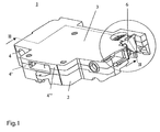
- FIGS. 1 to 6 show a structural unit 1 which has been formed by assembling a protective device 2 designed as a circuit breaker and a component 3 designed as a neutral conductor separator. This unit is intended for insertion into a low-voltage distributor, in particular on the basis of a plug-in base system or a mounting rail.
- the component 3 has a substantially box-shaped housing 4 made of a polymeric insulating material.
- the housing 4 contains interconnected parts, one of which rests on the protective device 2 as the lower part 4 'and the other is a freely accessible upper part 4.
- the housing 4 accommodates the active part that can be connected to a neutral conductor of the distributor and not visible in the figures of neutral neutralizer.
- the component 3 can also be designed as a contact block.
- the correspondingly formed housing 4 then takes on instead of the neutral conductor active auxiliary or signal contacts of the then executed as a switch protection device 2.
- the housing 4 can also accommodate a different functional group.
- the component 3 next to the housing 4 and enclosed by the housing and therefore not apparent function group contains two on the housing 4 held connecting elements 5 and 6 (Fig. 2), with which it is detachably connected to the protective device 2.
- the two connecting elements 5, 6 are guided to a side 7 of the housing 4 formed by the lower part 4 ', which serves to support the protective device 2 (FIGS. 3 and 4).
- the connecting element 5 is formed as a hook and fixedly disposed on the edge of the housing lower part 4 'on the housing side.
- the connecting element 6 is designed as a snap element and has a two-armed lever 8, the first arm carries a lockable on the protective device 2 hook 9 and the second arm carries a finger grip 10.
- the component 3 is hooked with the hook 5 on a recess 18 of the protective device 5 ( Figure 3) and positively applied by pivoting with the housing side 7 to the protective device 2.
- the hook 9 is first guided by striking its downwardly facing joining surface 14 at an undercut 15 of the protective device 2 in the counterclockwise direction to the right.
- the lever 9 is pivoted counterclockwise.
- the lever 9 is loaded during pivoting with a clockwise acting biasing force, which causes the hook 9 engages in the further joining operation in the undercut 15.
- the component 3 is now fixed via two connecting elements 5, 6 positively on the protective device 2.
- the two connecting elements namely the hook 5 and the executed as a twistable snap hook lever 9, each other on the housing side 7 diagonally opposite. Due to this positioning of the two connecting elements, the component 3 is held in a particularly stable position on the protective device 2.
- Other fasteners are then dispensable in general.
- retaining pins 19 may be formed in the housing side, which are inserted into corresponding recesses 20 of the protective device 2.
- the lever 8 When snapping the apparent from Fig.2 position of the two-armed lever 8 is reached, in which the finger grip 10 is an opening 16 of the housing 4 practically flush.
- the lever 8 is pivoted by pressing the finger grip 10 in the direction of arrow 17 against the force of the two torsion bars 12, 13 in the apparent from Figure 3 position.
- the finger grip 10 is arranged in the opening 16 of the housing 2 and the diameter of the housing opening 16 is smaller than the diameter of a finger
- the lever 8 can be pivoted only by a small angle, typically in the range between 5 ° and 15 ° become.
- the opening wall 16 limiting housing wall acts like a stop that secures the snap element 6 from overstretching. If necessary, an additional overstretch protection designed as a stop can be provided inside the housing.
- the finger grip 10 is pressed far enough into the housing, the positive locking is released and the component 3 can now be easily removed from the protective device 2, whereby the apparent from Fig.4 state is reached, in which the protective device 2 and the component. 3 completely separated from each other.
- the finger grip 9 is rotated out of the housing opening 15 by a small angular range, which is typically between 1 ° and 5 °.
- the housing opening 16 is located on a side facing away from the housing side 7 of the housing 4.
Abstract
Description
Die vorliegende Erfindung bezieht sich auf ein Bauteil zum lösbaren Befestigen an einem elektrischen Schutzgerät nach dem Oberbegriff von Patentanspruch 1. Das mit einem solchen Bauteil gekoppelte Schutzgerät wird bevorzugt eingesetzt in Niederspannungsverteilern auf der Basis einer Tragschiene oder eines Stecksockels mit parallel geführten und auf dem Stecksockel gehaltenen Sammelschienen. In Niederspannungsverteilern wird der aus einem Niederspannungsnetz gelieferte Strom mit Hilfe von Installationseinbauschaltern auf Komponenten, wie Leitungen, Motoren oder Apparate, oder auf Anlagen verteilt. Die Installationseinbauschalter sind als Schutzschalter ausgeführt. Die stromführenden Komponenten und Anlagen sind daher vor den Folgen von Überlast- und Kurzschlussströmen geschützt. Als Überspannungsableiter ausgeführte Schutzgeräte schützen die Komponenten und Anlagen vor Überspannung. An den Schutzgeräten können Bauteile mit bestimmten Funktionsgruppen lösbar befestigt werden, welche zusammen mit dem Schutzgerät im Niederspannungsverteiler installiert oder wieder aus dem Verteiler ausgebaut werden können.The present invention relates to a component for releasably attaching to an electrical protective device according to the preamble of
Ein Einbauteil der eingangs genannten Art ist beschrieben im Technischen Katalog smiss-line S "Innovation mit System - Schutzgeräte mit Stecktechnik" der Fa. ABB Schweiz AG, Normelec/CMC Components Postfach CH-9048 Zürich/Schweiz. Das vorbekannte Einbauteil weist ein kastenförmiges Gehäuse zur Aufnahme einer Funktionsgruppe auf. Ein bevorzugtes Einbauteil ist ein Neutralleitertrenner oder ein Kontaktblock mit Hilfs- oder mit Signalkontakten, welche jeweils einem als Schalter ausgeführten Schutzgerät zugeordnet sind.A built-in part of the type mentioned above is described in the technical catalog smiss-line S "Innovation with System - Protection devices with plug-in technology" from. ABB Switzerland AG, Normelec / CMC Components PO Box CH-9048 Zurich / Switzerland. The known installation part has a box-shaped housing for receiving a functional group. A preferred fitting is a Neutral conductor separator or a contact block with auxiliary or with signal contacts, which are each assigned to a designed as a switch protection device.
Das vorbekannte Bauteil weist an den Ecken einer Seite eines im wesentlichen kastenförmig ausgeführten Bauteilgehäuses vier jeweils als Schnapphaken ausgebildete Verbindungselemente auf. Zum Befestigen am Schutzgerät werden zwei dieser Schnapphaken in zwei entsprechende Vertiefungen des Schutzgerätes eingerastet und das Bauteil nach Art eines Scharniers geringfügig geschwenkt bis es mit seiner hakentragenden Gehäuseseite am Schutzgerät aufliegt. Die verbleibenden zwei Schnapphaken rasten dabei in zwei entsprechende Vertiefungen am Schutzgerät ein und setzen so das Bauteil am Schutzgerät fest. Zum Lösen des Bauteils vom Schutzgerät sind zwei der Schnappverbindungen gleichzeitig zu öffnen. Dies ist relativ aufwendig. Je nach manueller Geschicklichkeit des Monteurs ist hierbei zudem eine Beschädigung einer dieser Verbindungen nicht auszuschliessen.The previously known component has at the corners of one side of a substantially box-shaped component housing four each formed as snap hooks connecting elements. To attach to the protective device, two of these snap hooks are snapped into two corresponding recesses of the protective device and the component pivoted slightly in the manner of a hinge until it rests with its hook-carrying side of the housing on the device. The remaining two snap hooks snap into two corresponding recesses on the protection device and thus secure the component to the protection device. To release the component from the protective device, two of the snap-in connections must be opened simultaneously. This is relatively expensive. Depending on the manual dexterity of the installer, damage to one of these connections can not be ruled out.
Der Erfindung, wie sie in den Patentansprüchen angegeben ist, liegt die Aufgabe zugrunde, ein Bauteil der eingangs genannten Art zu schaffen, welches in einfacher und rascher Weise an einem Schutzgerät befestigt und bei Bedarf wieder bequem vom Schutzgerät gelöst werden kann.The invention, as indicated in the claims, the object is to provide a component of the type mentioned above, which can be attached in a simple and rapid manner to a protective device and conveniently released again when needed from the device.
Beim Bauteil nach der Erfindung ist ein Schnappelement vorgesehen mit einem mit Vorspannkraft beaufschlagbaren zweiarmigen Hebel, dessen erster Arm einen am Schutzgerät arretierbaren Haken und dessen zweiter Arm einen Fingergriff trägt. Mit einem derart gestalteten Schnappelement wird beim Zusammenfügen von Bauteil und Schutzgerät der Hebel zunächst in einer vorgegebenen Richtung geschwenkt und dabei mit Vorspannkraft belastet. Im weiteren Verlauf des Fügevorgangs verursacht die Vorspannkraft ein Schwenken des Hebels in Gegenrichtung. Hierbei schnappt der Haken unter Bildung eines Formschlusses in eine Vertiefung des Schutzgeräts ein. Durch den Formschluss der so gebildeten Schnappverbindung ist das Bauteil sicher am Schutzgerät festgesetzt. Bei Bedarf kann das Bauteil durch Betätigung des Fingergriffs bequem vom Schutzgerät gelöst werden. Bei dieser Betätigung wird im Hebel eine Vorspannkraft erzeugt, welche den Formschluss der Schnappverbindung rasch und bequem aufhebt. Das Bauteil kann nun sehr einfach vom Schutzgerät entfernt werden.In the component according to the invention, a snap element is provided with a biasing force acted upon two-armed lever, the first arm carries a lockable on the protective device hook and the second arm carries a finger grip. With a snap element designed in this way, the lever is first pivoted in a predetermined direction during assembly of the component and protective device and thereby loaded with biasing force. In the course of the joining process, the biasing force causes a pivoting of the lever in the opposite direction. This snaps the hook to form a positive connection in a recess of the protection device. Due to the positive connection of the snap connection thus formed, the component is securely fixed to the protection device. If necessary, the component can be easily removed from the protection device by actuating the finger grip be solved. In this operation, a biasing force is generated in the lever, which quickly and easily repeals the positive connection of the snap connection. The component can now be easily removed from the protection device.
Die erwünschte Vorspannkraft wird im allgemeinen mit einer Feder erreicht. Um Teile am Bauteil nach der Erfindung einzusparen, ist durch den Drehpunkt des zweiarmigen Hebels eine Schwenkachse geführt, welche mindestens einen am Gehäuse und am Hebel befestigten Torsionsstab enthält. Da die Schwenkachse einen Torsionsstab enthält, kann die erwünschte Vorspannkraft durch Verdrehen des Torsionsstabs erzeugt werden. Eine zur Erzeugung der Vorspannkraft sonst benötigte zusätzliche Feder kann daher eingespart werden.The desired biasing force is generally achieved with a spring. To save parts on the component according to the invention, a pivot axis is guided through the pivot point of the two-armed lever, which contains at least one torsion bar attached to the housing and the lever. Since the pivot axis includes a torsion bar, the desired biasing force can be generated by twisting the torsion bar. An additional spring otherwise required for generating the biasing force can therefore be saved.
Mit Vorteil enthält die Schwenkachse zwei Torsionsstäbe, welche zusammen mit dem Hebel integrierender Bestandteil des Gehäuses sind. Da das Gehäuse im allgemeinen aus einem polymeren Werkstoff gebildet ist, kann dann nämlich das Schnappelement zusammen mit einem Teil des Gehäuses einstückig in einem für eine Massenfertigung geeigneten Verfahren hergestellt werden, beispielsweise durch Spritzguss.Advantageously, the pivot axis comprises two torsion bars, which together with the lever are an integral part of the housing. Namely, since the housing is generally formed of a polymeric material, then the snap element together with a part of the housing can be made in one piece in a suitable method for mass production, for example by injection molding.
Eine sichere und vor der Einwirkung unerwünschter äusserer Kräfte geschützte Integration des Schnappelements in das Gehäuse wird erreicht, wenn der Fingergriff in einer Öffnung des Gehäuses gelagert ist. Hierbei kann der Durchmesser der Gehäuseöffnung kleiner als der Durchmesser eines Fingers sein, da so bei einer Betätigung der Fingergriff nur über einen definierten Weg ins Gehäuse gedrückt werden kann. Ein Überdehnen des Schnappelements wird durch die als Anschlag für den Finger dienende Begrenzung der Öffnung vermieden. Ein guter Zugang zum Fingergriff und damit eine bequeme Montage und Demontage sind sichergestellt, wenn die Gehäuseöffnung an einer von der Auflageseite abgewandten Seite des Gehäuses angeordnet und der zweiarmige Hebel als Winkelhebel ausgeführt ist.A secure and against the action of unwanted external forces protected integration of the snap element into the housing is achieved when the finger grip is mounted in an opening of the housing. In this case, the diameter of the housing opening may be smaller than the diameter of a finger, since the finger grip can thus only be pressed into the housing via a defined path when actuated. Overstretching of the snap element is avoided by serving as a stop for the finger boundary of the opening. A good access to the finger grip and thus a convenient assembly and disassembly are ensured when the housing opening arranged on a side facing away from the support side of the housing and the two-armed lever is designed as an angle lever.
Um das Zusammenfügen und Lösen von Bauteil und Schutzgerät zu erleichtern, ist an der Auflageseite ein feststehend angeordnetes und als Haken ausgeführtes Verbindungselement vorgesehen. Mit lediglich zwei Verbindungselementen wird bereits dann eine gute Befestigung erreicht, wenn der am Hebel vorgesehene Haken und der feststehend angeordnete Haken an der Auflageseite einander diagonal gegenüberstehen.In order to facilitate the assembly and release of component and protective device, a fixedly arranged and designed as a hook connecting element is provided on the support side. With only two fasteners a good attachment is already achieved when the provided on the lever Hook and the fixed arranged hook on the support side facing each other diagonally.
Eine das Bauteil nach der Erfindung und das damit fest verbundene Schutzgerät enthaltende Baueinheit kann als Schutzgerät einen Schalter aufweisen, welcher zum Einstecken in einen Niederspannungsverteiler, insbesondere mit einem sammelschienentragenden Stecksockel oder mit einer Tragschiene, bestimmt ist. Das Bauteil ist dann als Neutralleitertrenner ausgeführt oder als Kontaktblock zur Aufnahme von Hilfs- oder Signalkontakten des Schalters.A constructive unit containing the component according to the invention and the protective device fixedly connected therewith can have as a protective device a switch which is intended to be plugged into a low-voltage distributor, in particular with a busbar-supporting plug-in socket or with a mounting rail. The component is then designed as a neutral conductor separator or as a contact block for receiving auxiliary or signal contacts of the switch.
Anhand von Zeichnungen wird nachfolgend ein Ausführungsbeispiel der Erfindung näher erläutert. Hierbei zeigt:
- Fig.1
- in perspektivischer Darstellung eine Baueinheit, welche durch Zusammenfügen einer Ausführungsform eines Bauteils nach der Erfindung und eines Schutzgerätes gebildet ist,
- Fig.2
- eine Aufsicht auf einen längs II - II geführten Schnitt durch die Baueinheit nach Fig.1,
- Fig.3
- eine Aufsicht auf einen längs II - II geführten Schnitt durch die Baueinheit nach Fig.1 beim Entfernen des Bauteils vom Schutzgerät,
- Fig.4
- eine Aufsicht auf einen längs II - II geführten Schnitt durch die Baueinheit nach Fig.1 nach dem Entfernen des Bauteils vom Schutzgerät,
- Fig.5
- in Vergrösserung ein umrandet dargestellter Abschnitt der Baueinheit nach Fig.1, und
- Fig.6
- eine Ansicht auf einen längs VI - VI geführten Schnitt durch den Abschnitt gemäss Fig.5.
- Fig.1
- a perspective view of a structural unit, which is formed by joining together an embodiment of a component according to the invention and a protective device,
- Fig.2
- a plan view of a longitudinal II - II guided section through the assembly of Figure 1,
- Figure 3
- a plan view of a longitudinal II - II guided section through the assembly of Figure 1 when removing the component from the protection device,
- Figure 4
- a plan view of a longitudinal II - II guided section through the assembly of Figure 1 after removal of the component from the protective device,
- Figure 5
- in enlargement an outlined portion of the assembly of Figure 1, and
- Figure 6
- a view of a longitudinal VI - VI guided section through the section according to Figure 5.
In allen Figuren beziehen sich gleiche Bezugszeichen auf gleichwirkende Teile. In den Figuren 1 bis 6 ist eine Baueinheit 1 dargestellt, welche durch Zusammenfügen eines als Schutzschalter ausgeführten Schutzgeräts 2 und eines als Neutralleitertrenner ausgeführten Bauteils 3 gebildet wurde. Diese Baueinheit ist zum Einstecken in einen Niederspannungsverteiler, insbesondere auf der Basis eines Stecksockelsystems oder einer Tragschiene, bestimmt. Gemäss Fig.1 weist das Bauteil 3 ein im wesentlichen kastenförmiges Gehäuse 4 aus einem polymeren Isoliermaterial auf. Das Gehäuse 4 enthält durch Zusammenfügen miteinander verbundene Teile, von eines auf dem Schutzgerät 2 als Unterteil 4' aufliegt und das andere ein frei zugängliches Oberteil 4" ist. Das Gehäuse 4 nimmt das mit einem Neutralleiter des Verteilers verbindbare, aus den Figuren nicht ersichtliche Aktivteil des Neutralleitertrenners auf.In all figures, like reference numerals refer to like-acting parts. FIGS. 1 to 6 show a
Das Bauteil 3 kann auch als Kontaktblock ausgeführt sein. Das entsprechend ausgebildete Gehäuse 4 nimmt dann anstelle des Neutralleiteraktivteits Hilfs- oder Signalkontakte des dann als Schalter ausgeführten Schutzgeräts 2 auf. Anstelle der Aktivteile bzw. der Hilfs- oder Signalkontakte kann das Gehäuse 4 auch eine andere Funktionsgruppe aufnehmen. In jedem Fall enthält das Bauteil 3 neben dem Gehäuse 4 und der vom Gehäuse umschlossenen und daher nicht ersichtlichen Funktionsgruppe zwei am Gehäuse 4 gehaltene Verbindungselemente 5 und 6 (Fig. 2), mit denen es lösbar mit dem Schutzgerät 2 verbunden ist. Die beiden Verbindungselemente 5, 6 sind an eine vom Unterteil 4' gebildete Seite 7 des Gehäuses 4 geführt, die der Auflage des Schutzgeräts 2 dient (Figuren 3 und 4). Wie in den Figuren 2 bis 4 dargestellt, ist das Verbindungselement 5 als Haken ausgebildet und feststehend am Rande des Gehäuseunterteils 4' an der Gehäuseseite 7 angeordnet. Das Verbindungselement 6 ist als Schnappelement ausgebildet und weist einen zweiarmigen Hebel 8 auf, dessen erster Arm einen am Schutzgerät 2 arretierbaren Haken 9 und dessen zweiter Arm einen Fingergriff 10 trägt.The
In den Figuren 5 und 6 ist dargestellt, dass durch den Drehpunkt des zweiarmigen Hebels 8 eine Schwenkachse 11 geführt ist, welche zwei am Hebel 8 befestigte Torsionsstäbe 12, 13 enthält. Beide Torsionsstäbe 12, 13 und der Hebel 8 sind ersichtlich integrierender Bestandteil des Gehäuses 4. Diese Integration wird durch Spritzgiessen eines polymeren Werkstoffs erreicht. Hierbei wird bei der Fertigung des Oberteils 4" des Gehäuses 4 ein geeignet ausgebildetes Spritzwerkzeug verwendet, dem nach dem Spritzgiessen ein Werkstück entnommen werden kann, in das einstückig das Oberteil 4", die beiden Torsionsstäbe 12, 13 und der Hebel 8 eingeformt sind. Um Kerbwirkungen gering zu halten, sind die Torsionsstäbe 12, 13 im allgemeinen jeweils als Rundstab ausgeführt. Ihre Masse liegen im Millimeterbereich und betragen für die Stablänge bzw. den Stabdurchmesser typischerweise 2 bis 6 Millimeter bzw. 1 bis 3 Millimeter.In the figures 5 and 6 it is shown that through the pivot point of the two-
Zum Befestigen des Bauteils 3 am Schutzgerät 2 wird das Bauteil 3 mit dem Haken 5 an einer Vertiefung 18 des Schutzgeräts 5 eingehängt (Fig.3) und durch Schwenken formschlüssig mit der Gehäuseseite 7 an das Schutzgerät 2 angelegt. Beim Anlegen an das Schutzgerät 2 wird der Haken 9 durch Anschlagen seiner nach unten weisenden Fügefläche 14 an einer Hinterschneidung 15 des Schutzgeräts 2 zunächst im Gegenuhrzeigersinn nach rechts geführt. Hierbei wird der Hebel 9 im Gegenuhrzeigersinn geschwenkt. Infolge seiner drehbaren Lagerung an den beiden Torsionsstäben 12 und 13 wird der Hebel 9 beim Schwenken mit einer im Uhrzeigersinn wirkenden Vorspannkraft belastet, welche bewirkt, dass der Haken 9 beim weiteren Fügevorgang in der Hinterschneidung 15 einrastet.To attach the
Wie Fig.2 entnommen werden kann, ist das Bauteil 3 nun über zwei Verbindungselemente 5, 6 formschlüssig am Schutzgerät 2 festgesetzt. Die beiden Verbindungselemente, nämlich der Haken 5 und der als tordierbarer Schnapphaken ausgeführte Hebel 9, stehen einander an der Gehäuseseite 7 diagonal gegenüber. Durch diese Positionierung der beiden Verbindungselemente wird das Bauteil 3 besonders lagestabil am Schutzgerät 2 gehalten. Weitere Verbindungselemente sind dann im allgemeinen entbehrlich. Zur Erhöhung der Stabilität können in die Gehäuseseite 7 Haltezapfen 19 eingeformt sein, welche in entsprechende Vertiefungen 20 des Schutzgerätes 2 eingeschoben sind.As can be seen from Figure 2, the
Beim Einrasten wird die aus Fig.2 ersichtliche Position des zweiarmigen Hebels 8 erreicht, bei der der Fingergriff 10 eine Öffnung 16 des Gehäuses 4 praktisch bündig abschliesst. Zum Lösen des mit dem Schutzgerät 2 fest verbundenen Bauteils 3 wird der Hebel 8 durch Drücken des Fingergriffs 10 in Richtung eines Pfeils 17 entgegen der Kraft der beiden Torsionsstäbe 12, 13 in die aus Fig.3 ersichtliche Lage geschwenkt. Dadurch, dass der Fingergriff 10 in der Öffnung 16 des Gehäuses 2 angeordnet ist und der Durchmesser der Gehäuseöffnung 16 kleiner als der Durchmesser eines Fingers ist, kann der Hebel 8 lediglich um einen kleinen Winkel, typischerweise im Bereich zwischen 5° und 15°, geschwenkt werden. Die die Öffnung 16 begrenzende Gehäusewand wirkt hierbei wie ein Anschlag, der das Schnappelement 6 vor Überdehnung sichert. Falls erforderlich kann im Gehäuseinneren ein als Anschlag ausgeführter zusätzlicher Überdehnschutz vorgesehen sein.When snapping the apparent from Fig.2 position of the two-
Sobald der Fingergriff 10 weit genug ins Gehäuse eingedrückt ist, wird der Formschluss der Verrastung aufgehoben und das Bauteil 3 kann nun vom Schutzgerät 2 leicht abgenommen werden, wodurch der aus Fig.4 ersichtliche Zustand erreicht ist, in dem das Schutzgerät 2 und das Bauteil 3 vollständig voneinder getrennt sind. Nach der Demontage ist der Fingergriff 9 um einen kleinen Winkelbereich, welcher typischerweise zwischen 1 ° und 5° liegt, aus der Gehäuseöffnung 15 herausgedreht.Once the
Die Gehäuseöffnung 16 befindet sich an einer von der Gehäuseseite 7 abgewandten Seite des Gehäuses 4. Durch diese Positionierung und durch gleichzeitige Ausbildung des zweiarmigen Hebels 8 als Winkelhebel ist der Fingergriff 10 bequem zugänglich, so dass Bauteil 3 und Schutzgerät 2 äusserst bequem miteinander verbunden oder voneinander gelöst werden können.The
- 11
- Baueinheitunit
- 22
- Schutzgerätapparatus
- 33
- Bauteil, NeutralleitertrennerComponent, Neutral Disconnector
- 44
- Gehäusecasing
- 4'4 '
- GehäuseunterteilHousing bottom
- 4"4 '
- GehäuseoberteilHousing top
- 5, 65, 6
- Verbindungselementefasteners
- 77
- Gehäuseseitecase side
- 88th
- zweiarmiger Hebeltwo-armed lever
- 99
- Hakenhook
- 1010
- Fingergrifffinger grip
- 1111
- Schwenkachseswivel axis
- 12, 1312, 13
- Torsionsstäbetorsion bars
- 1414
- Fügeflächejoining surface
- 1515
- Hinterschneidungundercut
- 1616
- Gehäuseöffnunghousing opening
- 1717
- Pfeilarrow
- 1818
- Vertiefungdeepening
- 1919
- Haltezapfenretaining pins
- 2020
- Vertiefungdeepening
Claims (11)
Priority Applications (4)
| Application Number | Priority Date | Filing Date | Title |
|---|---|---|---|
| DE502004011911T DE502004011911D1 (en) | 2004-11-24 | 2004-11-24 | Component for releasable attachment to an electrical protection device |
| ES04405730T ES2356241T3 (en) | 2004-11-24 | 2004-11-24 | COMPONENT FOR REMOVABLE FIXATION IN AN ELECTRICAL PROTECTION APPLIANCE. |
| AT04405730T ATE488856T1 (en) | 2004-11-24 | 2004-11-24 | COMPONENT FOR DETACHABLE ATTACHMENT TO AN ELECTRICAL PROTECTIVE DEVICE |
| EP04405730A EP1662533B1 (en) | 2004-11-24 | 2004-11-24 | Removably fixed component on a circuit breaker |
Applications Claiming Priority (1)
| Application Number | Priority Date | Filing Date | Title |
|---|---|---|---|
| EP04405730A EP1662533B1 (en) | 2004-11-24 | 2004-11-24 | Removably fixed component on a circuit breaker |
Publications (2)
| Publication Number | Publication Date |
|---|---|
| EP1662533A1 true EP1662533A1 (en) | 2006-05-31 |
| EP1662533B1 EP1662533B1 (en) | 2010-11-17 |
Family
ID=34932380
Family Applications (1)
| Application Number | Title | Priority Date | Filing Date |
|---|---|---|---|
| EP04405730A Active EP1662533B1 (en) | 2004-11-24 | 2004-11-24 | Removably fixed component on a circuit breaker |
Country Status (4)
| Country | Link |
|---|---|
| EP (1) | EP1662533B1 (en) |
| AT (1) | ATE488856T1 (en) |
| DE (1) | DE502004011911D1 (en) |
| ES (1) | ES2356241T3 (en) |
Cited By (6)
| Publication number | Priority date | Publication date | Assignee | Title |
|---|---|---|---|---|
| DE102006023464A1 (en) * | 2006-05-18 | 2007-11-22 | Siemens Ag | Sensor assembly with a wall mountable housing |
| EP2180494A1 (en) * | 2008-10-27 | 2010-04-28 | General Electric Company | Tool free auxiliary contact block |
| WO2011091822A1 (en) * | 2010-01-26 | 2011-08-04 | Abb Ag | Installation switchgear having lockable housing halves |
| WO2013064186A1 (en) * | 2011-11-03 | 2013-05-10 | Abb Ab | An auxiliary contact block |
| ITRM20130495A1 (en) * | 2013-09-06 | 2015-03-07 | Bticino Spa | MODULAR ELECTRICAL APPLIANCE INCLUDING COUPLING ELEMENTS TO CONNECT THE APPLIANCE WITH AN ADDITIONAL MODULAR ELECTRICAL APPLIANCE |
| EP4113567A4 (en) * | 2020-10-21 | 2023-10-18 | Fuji Electric Fa Components & Systems Co., Ltd. | Auxiliary contact unit |
Citations (4)
| Publication number | Priority date | Publication date | Assignee | Title |
|---|---|---|---|---|
| FR2550907A1 (en) * | 1983-08-17 | 1985-02-22 | Merlin Gerin | DEVICE FOR ASSEMBLING ELECTRICAL EQUIPMENT MODULES |
| EP0223622A1 (en) * | 1985-10-09 | 1987-05-27 | Telemecanique | Assembling device for modular units of electrical equipment |
| EP0375568A1 (en) | 1988-12-14 | 1990-06-27 | Merlin Gerin | Modulator assembly device for a multipole differential circuit breaker |
| EP0986136A2 (en) * | 1998-09-08 | 2000-03-15 | GEWISS S.p.A. | Safety connection device, particularly for modular electrical devices |
-
2004
- 2004-11-24 DE DE502004011911T patent/DE502004011911D1/en active Active
- 2004-11-24 EP EP04405730A patent/EP1662533B1/en active Active
- 2004-11-24 ES ES04405730T patent/ES2356241T3/en active Active
- 2004-11-24 AT AT04405730T patent/ATE488856T1/en not_active IP Right Cessation
Patent Citations (4)
| Publication number | Priority date | Publication date | Assignee | Title |
|---|---|---|---|---|
| FR2550907A1 (en) * | 1983-08-17 | 1985-02-22 | Merlin Gerin | DEVICE FOR ASSEMBLING ELECTRICAL EQUIPMENT MODULES |
| EP0223622A1 (en) * | 1985-10-09 | 1987-05-27 | Telemecanique | Assembling device for modular units of electrical equipment |
| EP0375568A1 (en) | 1988-12-14 | 1990-06-27 | Merlin Gerin | Modulator assembly device for a multipole differential circuit breaker |
| EP0986136A2 (en) * | 1998-09-08 | 2000-03-15 | GEWISS S.p.A. | Safety connection device, particularly for modular electrical devices |
Cited By (14)
| Publication number | Priority date | Publication date | Assignee | Title |
|---|---|---|---|---|
| DE102006023464A1 (en) * | 2006-05-18 | 2007-11-22 | Siemens Ag | Sensor assembly with a wall mountable housing |
| DE102006023464B4 (en) * | 2006-05-18 | 2010-04-15 | Continental Automotive Gmbh | Sensor assembly with a wall mountable housing |
| US8210037B2 (en) | 2006-05-18 | 2012-07-03 | Continental Automotive Gmbh | Sensor module with a housing which may be mounted on a wall |
| EP2180494A1 (en) * | 2008-10-27 | 2010-04-28 | General Electric Company | Tool free auxiliary contact block |
| CN101728095A (en) * | 2008-10-27 | 2010-06-09 | 通用电气公司 | Tool free auxiliary contact block |
| WO2011091822A1 (en) * | 2010-01-26 | 2011-08-04 | Abb Ag | Installation switchgear having lockable housing halves |
| WO2013064186A1 (en) * | 2011-11-03 | 2013-05-10 | Abb Ab | An auxiliary contact block |
| US8921713B2 (en) | 2011-11-03 | 2014-12-30 | Abb Ab | Auxiliary contact block |
| RU2578127C2 (en) * | 2011-11-03 | 2016-03-20 | Абб Текнолоджи Лтд. | Unit of auxiliary contacts |
| ITRM20130495A1 (en) * | 2013-09-06 | 2015-03-07 | Bticino Spa | MODULAR ELECTRICAL APPLIANCE INCLUDING COUPLING ELEMENTS TO CONNECT THE APPLIANCE WITH AN ADDITIONAL MODULAR ELECTRICAL APPLIANCE |
| EP2846345A1 (en) * | 2013-09-06 | 2015-03-11 | Bticino S.P.A. | Modular electrical apparatus comprising coupling elements for coupling said apparatus to a further modular electrical apparatus |
| CN104427809A (en) * | 2013-09-06 | 2015-03-18 | 布蒂克诺公司 | Modular electrical apparatus and part assembly comprising coupled modular electrical apparatuses |
| RU2668286C2 (en) * | 2013-09-06 | 2018-09-28 | Бтичино С.П.А. | Modular electrical device comprising connecting elements for connecting with another modular electrical device |
| EP4113567A4 (en) * | 2020-10-21 | 2023-10-18 | Fuji Electric Fa Components & Systems Co., Ltd. | Auxiliary contact unit |
Also Published As
| Publication number | Publication date |
|---|---|
| ES2356241T3 (en) | 2011-04-06 |
| EP1662533B1 (en) | 2010-11-17 |
| ATE488856T1 (en) | 2010-12-15 |
| DE502004011911D1 (en) | 2010-12-30 |
Similar Documents
| Publication | Publication Date | Title |
|---|---|---|
| EP2018646B1 (en) | Switching device, in particular fused interrupters | |
| EP1701369B1 (en) | Electromechanical circuit breaker | |
| WO2001069738A1 (en) | Adapter plate and system for mounting a component on an assembly base | |
| DE4000717C2 (en) | Surge arresters | |
| DE19525438A1 (en) | Busbar adapter system | |
| EP3510676B1 (en) | Overvoltage protection module for a modular plug connector | |
| DE202021000293U1 (en) | Data exchange device and arrangement | |
| DE102007015470A1 (en) | Snap fastening for fastening a housing | |
| EP1662533B1 (en) | Removably fixed component on a circuit breaker | |
| WO2019110414A1 (en) | Adapter for installing electrotechnical components | |
| DE10003349A1 (en) | Holding device for fastening at least one electrical switching device on a top-hat rail | |
| DE3802074A1 (en) | Plastic housing, which can be snapped onto an apparatus supporting rail, for electrical service apparatuses | |
| EP1638123B1 (en) | Protective switch with slidable contact-plug | |
| DE102006006914B4 (en) | Device for fixing a connector on a support element | |
| EP1715500B1 (en) | Auxiliary switch for low-voltage electrical distribution board | |
| DE102015111885A1 (en) | Fuse for power distributor | |
| DE102006060231B4 (en) | Electrical / electronic installation device | |
| EP0555665B1 (en) | Outlet box, especially for busways | |
| EP1376793B1 (en) | Adapter for the installation of terminal blocks in electric distribution devices | |
| DE3729616C2 (en) | ||
| EP2656366B1 (en) | Star-delta wiring, especially for a protection circuit on a mounting plate | |
| EP1289085A1 (en) | Plug-in module for a medium voltage distributor | |
| EP1662534B1 (en) | Module for releasably latching to a circiut breaker | |
| EP0123040A2 (en) | Terminal board for electric and electronic apparatuses, e.g. overcurrent protection switches | |
| DE102015017297B4 (en) | Fusible link and connection arrangement with such a fuse |
Legal Events
| Date | Code | Title | Description |
|---|---|---|---|
| PUAI | Public reference made under article 153(3) epc to a published international application that has entered the european phase |
Free format text: ORIGINAL CODE: 0009012 |
|
| AK | Designated contracting states |
Kind code of ref document: A1 Designated state(s): AT BE BG CH CY CZ DE DK EE ES FI FR GB GR HU IE IS IT LI LU MC NL PL PT RO SE SI SK TR |
|
| AX | Request for extension of the european patent |
Extension state: AL HR LT LV MK YU |
|
| 17P | Request for examination filed |
Effective date: 20060819 |
|
| AKX | Designation fees paid |
Designated state(s): AT BE BG CH CY CZ DE DK EE ES FI FR GB GR HU IE IS IT LI LU MC NL PL PT RO SE SI SK TR |
|
| 17Q | First examination report despatched |
Effective date: 20080506 |
|
| GRAP | Despatch of communication of intention to grant a patent |
Free format text: ORIGINAL CODE: EPIDOSNIGR1 |
|
| RIN1 | Information on inventor provided before grant (corrected) |
Inventor name: SCHEFFER, KATJA Inventor name: SCHALK, ADELBERT |
|
| GRAS | Grant fee paid |
Free format text: ORIGINAL CODE: EPIDOSNIGR3 |
|
| GRAA | (expected) grant |
Free format text: ORIGINAL CODE: 0009210 |
|
| AK | Designated contracting states |
Kind code of ref document: B1 Designated state(s): AT BE BG CH CY CZ DE DK EE ES FI FR GB GR HU IE IS IT LI LU MC NL PL PT RO SE SI SK TR |
|
| REG | Reference to a national code |
Ref country code: GB Ref legal event code: FG4D Free format text: NOT ENGLISH |
|
| REG | Reference to a national code |
Ref country code: CH Ref legal event code: EP |
|
| REG | Reference to a national code |
Ref country code: IE Ref legal event code: FG4D |
|
| REF | Corresponds to: |
Ref document number: 502004011911 Country of ref document: DE Date of ref document: 20101230 Kind code of ref document: P |
|
| REG | Reference to a national code |
Ref country code: NL Ref legal event code: VDEP Effective date: 20101117 |
|
| REG | Reference to a national code |
Ref country code: ES Ref legal event code: FG2A Ref document number: 2356241 Country of ref document: ES Kind code of ref document: T3 Effective date: 20110406 |
|
| BERE | Be: lapsed |
Owner name: ABB SCHWEIZ A.G. Effective date: 20101130 |
|
| PG25 | Lapsed in a contracting state [announced via postgrant information from national office to epo] |
Ref country code: CY Free format text: LAPSE BECAUSE OF FAILURE TO SUBMIT A TRANSLATION OF THE DESCRIPTION OR TO PAY THE FEE WITHIN THE PRESCRIBED TIME-LIMIT Effective date: 20101117 Ref country code: NL Free format text: LAPSE BECAUSE OF FAILURE TO SUBMIT A TRANSLATION OF THE DESCRIPTION OR TO PAY THE FEE WITHIN THE PRESCRIBED TIME-LIMIT Effective date: 20101117 Ref country code: SI Free format text: LAPSE BECAUSE OF FAILURE TO SUBMIT A TRANSLATION OF THE DESCRIPTION OR TO PAY THE FEE WITHIN THE PRESCRIBED TIME-LIMIT Effective date: 20101117 Ref country code: IS Free format text: LAPSE BECAUSE OF FAILURE TO SUBMIT A TRANSLATION OF THE DESCRIPTION OR TO PAY THE FEE WITHIN THE PRESCRIBED TIME-LIMIT Effective date: 20110317 Ref country code: SE Free format text: LAPSE BECAUSE OF FAILURE TO SUBMIT A TRANSLATION OF THE DESCRIPTION OR TO PAY THE FEE WITHIN THE PRESCRIBED TIME-LIMIT Effective date: 20101117 Ref country code: FI Free format text: LAPSE BECAUSE OF FAILURE TO SUBMIT A TRANSLATION OF THE DESCRIPTION OR TO PAY THE FEE WITHIN THE PRESCRIBED TIME-LIMIT Effective date: 20101117 Ref country code: PT Free format text: LAPSE BECAUSE OF FAILURE TO SUBMIT A TRANSLATION OF THE DESCRIPTION OR TO PAY THE FEE WITHIN THE PRESCRIBED TIME-LIMIT Effective date: 20110317 Ref country code: BG Free format text: LAPSE BECAUSE OF FAILURE TO SUBMIT A TRANSLATION OF THE DESCRIPTION OR TO PAY THE FEE WITHIN THE PRESCRIBED TIME-LIMIT Effective date: 20110217 |
|
| REG | Reference to a national code |
Ref country code: IE Ref legal event code: FD4D |
|
| PG25 | Lapsed in a contracting state [announced via postgrant information from national office to epo] |
Ref country code: MC Free format text: LAPSE BECAUSE OF NON-PAYMENT OF DUE FEES Effective date: 20101130 Ref country code: GR Free format text: LAPSE BECAUSE OF FAILURE TO SUBMIT A TRANSLATION OF THE DESCRIPTION OR TO PAY THE FEE WITHIN THE PRESCRIBED TIME-LIMIT Effective date: 20110218 |
|
| REG | Reference to a national code |
Ref country code: CH Ref legal event code: PL |
|
| PG25 | Lapsed in a contracting state [announced via postgrant information from national office to epo] |
Ref country code: CZ Free format text: LAPSE BECAUSE OF FAILURE TO SUBMIT A TRANSLATION OF THE DESCRIPTION OR TO PAY THE FEE WITHIN THE PRESCRIBED TIME-LIMIT Effective date: 20101117 Ref country code: CH Free format text: LAPSE BECAUSE OF NON-PAYMENT OF DUE FEES Effective date: 20101130 Ref country code: LI Free format text: LAPSE BECAUSE OF NON-PAYMENT OF DUE FEES Effective date: 20101130 Ref country code: IE Free format text: LAPSE BECAUSE OF FAILURE TO SUBMIT A TRANSLATION OF THE DESCRIPTION OR TO PAY THE FEE WITHIN THE PRESCRIBED TIME-LIMIT Effective date: 20101117 Ref country code: EE Free format text: LAPSE BECAUSE OF FAILURE TO SUBMIT A TRANSLATION OF THE DESCRIPTION OR TO PAY THE FEE WITHIN THE PRESCRIBED TIME-LIMIT Effective date: 20101117 |
|
| PG25 | Lapsed in a contracting state [announced via postgrant information from national office to epo] |
Ref country code: PL Free format text: LAPSE BECAUSE OF FAILURE TO SUBMIT A TRANSLATION OF THE DESCRIPTION OR TO PAY THE FEE WITHIN THE PRESCRIBED TIME-LIMIT Effective date: 20101117 Ref country code: RO Free format text: LAPSE BECAUSE OF FAILURE TO SUBMIT A TRANSLATION OF THE DESCRIPTION OR TO PAY THE FEE WITHIN THE PRESCRIBED TIME-LIMIT Effective date: 20101117 Ref country code: DK Free format text: LAPSE BECAUSE OF FAILURE TO SUBMIT A TRANSLATION OF THE DESCRIPTION OR TO PAY THE FEE WITHIN THE PRESCRIBED TIME-LIMIT Effective date: 20101117 Ref country code: BE Free format text: LAPSE BECAUSE OF NON-PAYMENT OF DUE FEES Effective date: 20101130 Ref country code: SK Free format text: LAPSE BECAUSE OF FAILURE TO SUBMIT A TRANSLATION OF THE DESCRIPTION OR TO PAY THE FEE WITHIN THE PRESCRIBED TIME-LIMIT Effective date: 20101117 |
|
| PLBE | No opposition filed within time limit |
Free format text: ORIGINAL CODE: 0009261 |
|
| STAA | Information on the status of an ep patent application or granted ep patent |
Free format text: STATUS: NO OPPOSITION FILED WITHIN TIME LIMIT |
|
| 26N | No opposition filed |
Effective date: 20110818 |
|
| REG | Reference to a national code |
Ref country code: DE Ref legal event code: R097 Ref document number: 502004011911 Country of ref document: DE Effective date: 20110818 |
|
| REG | Reference to a national code |
Ref country code: AT Ref legal event code: MM01 Ref document number: 488856 Country of ref document: AT Kind code of ref document: T Effective date: 20101124 |
|
| PG25 | Lapsed in a contracting state [announced via postgrant information from national office to epo] |
Ref country code: AT Free format text: LAPSE BECAUSE OF NON-PAYMENT OF DUE FEES Effective date: 20101124 |
|
| PG25 | Lapsed in a contracting state [announced via postgrant information from national office to epo] |
Ref country code: LU Free format text: LAPSE BECAUSE OF NON-PAYMENT OF DUE FEES Effective date: 20101124 Ref country code: HU Free format text: LAPSE BECAUSE OF FAILURE TO SUBMIT A TRANSLATION OF THE DESCRIPTION OR TO PAY THE FEE WITHIN THE PRESCRIBED TIME-LIMIT Effective date: 20110518 |
|
| PG25 | Lapsed in a contracting state [announced via postgrant information from national office to epo] |
Ref country code: TR Free format text: LAPSE BECAUSE OF FAILURE TO SUBMIT A TRANSLATION OF THE DESCRIPTION OR TO PAY THE FEE WITHIN THE PRESCRIBED TIME-LIMIT Effective date: 20101117 |
|
| PGFP | Annual fee paid to national office [announced via postgrant information from national office to epo] |
Ref country code: ES Payment date: 20141126 Year of fee payment: 11 Ref country code: GB Payment date: 20141119 Year of fee payment: 11 |
|
| REG | Reference to a national code |
Ref country code: FR Ref legal event code: PLFP Year of fee payment: 12 |
|
| GBPC | Gb: european patent ceased through non-payment of renewal fee |
Effective date: 20151124 |
|
| PG25 | Lapsed in a contracting state [announced via postgrant information from national office to epo] |
Ref country code: GB Free format text: LAPSE BECAUSE OF NON-PAYMENT OF DUE FEES Effective date: 20151124 |
|
| REG | Reference to a national code |
Ref country code: FR Ref legal event code: PLFP Year of fee payment: 13 |
|
| REG | Reference to a national code |
Ref country code: ES Ref legal event code: FD2A Effective date: 20161230 |
|
| PG25 | Lapsed in a contracting state [announced via postgrant information from national office to epo] |
Ref country code: ES Free format text: LAPSE BECAUSE OF NON-PAYMENT OF DUE FEES Effective date: 20151125 |
|
| REG | Reference to a national code |
Ref country code: FR Ref legal event code: PLFP Year of fee payment: 14 |
|
| PGFP | Annual fee paid to national office [announced via postgrant information from national office to epo] |
Ref country code: FR Payment date: 20181123 Year of fee payment: 15 Ref country code: IT Payment date: 20181126 Year of fee payment: 15 |
|
| PG25 | Lapsed in a contracting state [announced via postgrant information from national office to epo] |
Ref country code: FR Free format text: LAPSE BECAUSE OF NON-PAYMENT OF DUE FEES Effective date: 20191130 Ref country code: IT Free format text: LAPSE BECAUSE OF NON-PAYMENT OF DUE FEES Effective date: 20191124 |
|
| PGFP | Annual fee paid to national office [announced via postgrant information from national office to epo] |
Ref country code: DE Payment date: 20231121 Year of fee payment: 20 |