EP1376793B1 - Adapter for the installation of terminal blocks in electric distribution devices - Google Patents
Adapter for the installation of terminal blocks in electric distribution devices Download PDFInfo
- Publication number
- EP1376793B1 EP1376793B1 EP20030013689 EP03013689A EP1376793B1 EP 1376793 B1 EP1376793 B1 EP 1376793B1 EP 20030013689 EP20030013689 EP 20030013689 EP 03013689 A EP03013689 A EP 03013689A EP 1376793 B1 EP1376793 B1 EP 1376793B1
- Authority
- EP
- European Patent Office
- Prior art keywords
- adapter
- strip
- connection
- adapter according
- latching
- Prior art date
- Legal status (The legal status is an assumption and is not a legal conclusion. Google has not performed a legal analysis and makes no representation as to the accuracy of the status listed.)
- Expired - Fee Related
Links
Images

Classifications
-
- H—ELECTRICITY
- H02—GENERATION; CONVERSION OR DISTRIBUTION OF ELECTRIC POWER
- H02B—BOARDS, SUBSTATIONS OR SWITCHING ARRANGEMENTS FOR THE SUPPLY OR DISTRIBUTION OF ELECTRIC POWER
- H02B1/00—Frameworks, boards, panels, desks, casings; Details of substations or switching arrangements
- H02B1/015—Boards, panels, desks; Parts thereof or accessories therefor
- H02B1/04—Mounting thereon of switches or of other devices in general, the switch or device having, or being without, casing
- H02B1/052—Mounting on rails
-
- H—ELECTRICITY
- H02—GENERATION; CONVERSION OR DISTRIBUTION OF ELECTRIC POWER
- H02B—BOARDS, SUBSTATIONS OR SWITCHING ARRANGEMENTS FOR THE SUPPLY OR DISTRIBUTION OF ELECTRIC POWER
- H02B1/00—Frameworks, boards, panels, desks, casings; Details of substations or switching arrangements
- H02B1/015—Boards, panels, desks; Parts thereof or accessories therefor
- H02B1/04—Mounting thereon of switches or of other devices in general, the switch or device having, or being without, casing
- H02B1/042—Mounting on perforated supports by means of screws or locking members
Definitions
- the invention relates to an adapter for the installation of terminal block modules in electrical distribution devices, wherein the adapter comprises means for connection to at least one such module and means for connection to a Hutprofilaschiene comprising elastically latching hook elements on the opposite longitudinal edges of the Hutprofilaschiene.
- Adapters of this kind go out of the EP 0 610 710 A1 as well as the DE 297 06 755 U1 out.
- the former document describes two U-shaped, a module receiving adapter parts, which are displaceable against the module in its entirety by spring elements with engagement of the hook elements on the Hutprofilaschiene.
- the from the DE 297 06 755 U1 known adapter comprises a latchable on the Hutprofilaschiene support plate which is bolted to a module-carrying headband, wherein the headband can be attached to the support plate in different positions.
- terminal strips for electrical distribution devices in particular PE / N terminal strips of modules, which are connected to a common carrier strip, which is held at their ends to support frames, for example, projecting from the bottom of a distribution box.
- the object of the present invention is to expand the possible uses of such terminal block modules used to form connection strips.
- an adapter of the type mentioned above which is characterized in that the adapter is designed as an adapter strip in the form of an elongated angle profile and the elastically latching hook elements for engaging the adapter bar on the longitudinal edges of the Hutprofilaschiene both parallel and transverse to Hutprofiltrögerschiene are provided.
- this invention provides solution options with respect to the installation of terminal block modules or terminal blocks formed therefrom. Ultimately, this makes it possible to make better use of the space available in distribution devices.
- the adapter may further comprise means for selectively connecting to at least one other to the Hutprofil schiene different, used in distribution devices carrier element.
- the further carrier element is a carrier rail or a carrier plate.
- Such support elements are usually used in distributor devices in addition to Hutprofil as a component carrier.
- the adapter can expediently be attached with the aid of projecting domes, which have a bottom opening for a screw connection to the carrier plate.
- the connecting means of the adapter on connecting elements which are used multiple times in the context of the connection of the adapter with different support elements and / or with a support member in different arrangements.
- the effort required to produce the connecting devices can thus be reduced.
- the adapter strip can be provided with predetermined breaking points for adapting the strip length to different lengths of terminal strip modules.
- the inner sides of the angle profile form a seat for the terminal block module, wherein the module, for example, on one of the angle leg via a laterally attached to its housing terminal with snap on the angle leg can be plugged and for positive retention on the bar further with a housing projection into a recess in engages the other angle leg.
- the above-mentioned dome for the screw connection with the support plate may be formed, while on the other leg, the mentioned elastically latching form-fitting connection elements are mounted.
- the angle profile expediently remains open at the ends and even ends flush with the terminal block module.
- the strips can then be placed against each other under direct juxtaposition of the terminal block modules and used for the electrical connection of the modules for direct juxtaposition of the module sized connection bridges.
- the dome are arranged near or on the longitudinal center line of the leg concerned. With parallel attachment of the adapter strip on a DIN rail, the dome then find place within the hat profile.
- the elastically latching positive connection elements in the manner of a rocker arm with a carrier rail engaging behind latching lug are formed on a Hebelarmende.
- the rocker arm e.g. in its longitudinal center can be connected via elastically bendable webs with one of the angle leg, can be solved by applying force to the Rastnqse opposite end of the lever from its entanglement with the support rail.
- the locking lug is adapted to be adapted to different support rail thicknesses step-shaped.
- Vorteifhaft attacks are also provided for the system against a side surface of the support rail, which prevent a displacement of the adapter bar transverse to the support rail.
- the solution of the positive connection between the adapter strip and carrier rail can then be solved only by operating the rocker-shaped connection element, as described above.
- connection means for connecting the adapter bar to a carrier rail are formed in an array both longitudinally and transversely thereto.
- an elastic locking lip provided and formed in the bar an opening for the introduction of a tool for releasing the locking connection by bending the locking lip.
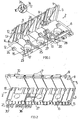
- the adapter strip 2 is formed in its rough outlines as an angle section with a leg 5 and a leg 6 angled to 90 °.
- the adapter strip 2 has in the relevant embodiment, five predetermined breaking points 7, which by opposing one another Grooves are formed on both leg sides, which extend transversely over both the leg 5 and the leg 6.
- openings 8 are formed for the engagement of locking lugs of a Kirsten terminal connection module, wherein in the considered embodiment, seven such openings are provided.
- Two projections 9 arranged at the longitudinal ends of the leg 5 serve as lateral fixing stops for the module.
- the two locking elements 10 are attached, which are connected by connecting webs 11 elastically connected to the leg 5.
- the two locking elements 10 each have at one end a locking lug 12.
- the locking lug 12 is formed stepwise with a first stage 34 and a second stage 35.
- In the grid spacing of the predetermined breaking points further webs 13 are mounted in triangular form on the leg 5 on the outside. Some of these webs have a stop lug 14 at a free triangle corner.
- the leg 6 is provided at its free, the angled opposite longitudinal edge with a chamfer 15, which carries a numbering inscription. From the leg 6 are outside the outside of three dome 16 with a bottom opening 17 before.
- the leg 6 has, at its longitudinal edge facing the leg 5, recesses 18 for engagement of a lug on the housing of a terminal connection module which can be plugged onto the adapter strip.
- recesses 18 When separating the strip at a predetermined breaking point, further such recesses 18 open on two sides arise.
- hook-shaped connecting elements 23 are provided on the leg 6 on the outside at the free longitudinal edge in the relevant embodiment. Further such hook connecting elements 24 are arranged between the free longitudinal edge and the bend in a row parallel to the longitudinal edge or the bend.
- One of the hook connection elements 23 and one of the hook connection elements 24 has in each case an additional hook part 25 or 26, which protrudes in the longitudinal direction of the adapter strip.
- the hook parts opposite an elastic, curved locking lip 27 and a stop 28 are formed.
- the free end of the bent latching lip 27 projects into an opening 36 formed in the leg 6.
- leg 6 has numerous depressions to avoid accumulation of material.
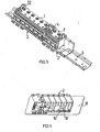
- the adapter bar 2 can be both parallel and transverse to the longitudinal direction of a DIN rail 3 'attach.
- the hook connection elements 23 engage behind a hat rim 29 of the hat profile when the adapter strip is tilted slightly onto the top-hat rail 3 'and is displaced transversely thereto.
- the stop lugs 14 of the webs 13 come to rest against the edge surface of the hat brim 30 and the webs 13 sit on the hat brim 30.
- a transverse displacement of the adapter strip 2 under release of the locking elements 10 from the hooking position is excluded by the stop lugs 14.
- the locking elements 10 are tilted by exerting a compressive force on the locking lug 12 opposite end of the lever bending the connecting webs 11 and thereby brought the locking lug 12 from the Verhakungseingriff with the brim 30.
- the adapter strip 2 can now tilt back again and remove the hooking elements 23 from the top-hat rail 3 'by releasing the entanglements.
- the hook parts 25 and 26, the curved locking lip 27 and the stop 28 are used, as is made Fig. 4 evident.
- the hook parts 25 and 26 engage over the brim 30 of the hat profile rail 3 '. After a rotation of the bar then engages the lip 27 at the hat brim 29 a.
- the elastic locking lip 27 can be bent by an engaging into the opening 36 tool.
- a plurality of adapter strips 2 and 2 ' can be strung together to form a longer terminal strip on the DIN rail 3 and on the juxtaposed adapter strips Klemman gleichrucnmodule 1 and 1' plugged. by completing the Klemman gleichrucnmodule flush with the longitudinal end of the adapter bar, they are also within the longer terminal block directly to each other and can be electrically connected to each other over this case provided standard bridges.
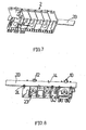
- FIG. 6 Referring to where the adapter strip 2 is shown in connection with a support plate 31.
- the installable in an electrical distribution device carrier plate 31 has holes for a screw connection, wherein fastening screws 32 are guided through the bottom openings 17 in the domes 16.
- FIGS. 7 and 8 show a further mounting option on a installable in a distribution device carrier element, which is formed in the case in question by a flat carrier rail 33 with a rectangular cross-section.
- the hook connecting elements 24 are used, which engage over the edge of the support rail 33. Because of the greater thickness of the rail 33 relative to the crown thickness of the cap profile rail 3 ', the lugs 12 engage with their step 34.
Description
Die Erfindung betrifft einen Adapter für die Installation von Anschlussleistenmodulen in elektrischen Verteilereinrichtungen, wobei der Adapter Einrichtungen zur Verbindung mit wenigstens einem solchen Modul sowie Einrichtungen zur Verbindung mit einer Hutprofilträgerschiene aufweist, welche an den einander gegenüberliegenden Längsrändern der Hutprofilträgerschiene elastisch einrastende Hakenelemente umfasst.The invention relates to an adapter for the installation of terminal block modules in electrical distribution devices, wherein the adapter comprises means for connection to at least one such module and means for connection to a Hutprofilträgerschiene comprising elastically latching hook elements on the opposite longitudinal edges of the Hutprofilträgerschiene.
Adapter solcher Art gehen aus der
Aus der
Der vorliegenden Erfindung liegt die Aufgabe zugrunde, die Einsatzmöglichkeiten solcher, zur Bildung von Anschlussleisten verwendeter Anschlussleistenmodule zu erweitern.The object of the present invention is to expand the possible uses of such terminal block modules used to form connection strips.
Diese Aufgabe wird durch einen Adapter der eingangs erwähnten Art gelöst, der dadurch gekennzeichnet ist, dass der Adapter als Adapterleiste in der Form eines länglichen Winkelprofils ausgebildet ist und die elastisch einrastenden Hakenelemente zum Einrasten der Adapterleiste an den Längsrändern der Hutprofilträgerschiene sowohl parallel als auch quer zur Hutprofiltrögerschiene vorgesehen sind.This object is achieved by an adapter of the type mentioned above, which is characterized in that the adapter is designed as an adapter strip in the form of an elongated angle profile and the elastically latching hook elements for engaging the adapter bar on the longitudinal edges of the Hutprofilträgerschiene both parallel and transverse to Hutprofiltrögerschiene are provided.
Vorteilhaft ergeben sich durch diese Erfindungslösung Variationsmöglichkeiten in bezug auf die Installation von Anschlussleistenmodulen bzw. daraus gebildeten Anschlussleisten. Letztlich lässt sich hierdurch der in Verteilereinrichtungen zur Verfügung stehende Bauraum besser nutzen.Advantageously, this invention provides solution options with respect to the installation of terminal block modules or terminal blocks formed therefrom. Ultimately, this makes it possible to make better use of the space available in distribution devices.
Der Adapter kann ferner Einrichtungen zur wahlweisen Verbindung mit wenigstens einem weiteren zu der Hutprofilträgerschiene unterschiedlichen, in Verteilereinrichtungen verwendeten Trägerelement aufweisen.The adapter may further comprise means for selectively connecting to at least one other to the Hutprofilträgerschiene different, used in distribution devices carrier element.
Vorzugsweise handelt es sich bei dem weiteren Trägerelement um eine Trägerschiene oder eine Trägerplatte. Solche Trägerelemente werden in Verteilereinrichtungen neben Hutprofilträgerschienen üblicherweise als Bauteilträger eingesetzt.Preferably, the further carrier element is a carrier rail or a carrier plate. Such support elements are usually used in distributor devices in addition to Hutprofilträgerschienen as a component carrier.
Durch die elastisch einrastenden Hakenelemente lässt sich bequem mit geringem Arbeitsaufwand eine Verbindung zwischen dem Adapter und dem betreffenden Trägerelement herstellen.Due to the elastically latching hook elements can be easily with little effort a connection between the adapter and the support element concerned produce.
An der Trägerplatte lässt sich der Adapter zweckmäßig mit Hilfe vorstehender Dome anbringen, die eine Bodenöffnung für eine Schraubverbindung mit der Trägerplatte aufweisen.On the carrier plate, the adapter can expediently be attached with the aid of projecting domes, which have a bottom opening for a screw connection to the carrier plate.
In weiterer Ausgestaltung der Erfindung weisen die Verbindungseinrichtungen des Adapters Verbindungselemente auf, die im Rahmen der Verbindung des Adapters mit unterschiedlichen Trägerelementen oder/und mit einem Trägerelement in dazu unterschiedlichen Anordnungen mehrfach nutzbar sind. Vorteilhaft kann so der zur Herstellung der Verbindungseinrichtungen erforderliche Aufwand verringert werden.In a further embodiment of the invention, the connecting means of the adapter on connecting elements, which are used multiple times in the context of the connection of the adapter with different support elements and / or with a support member in different arrangements. Advantageously, the effort required to produce the connecting devices can thus be reduced.
Die Adapterleiste kann mit Sollbruchstellen zur Anpassung der Leistenlänge an unterschiedliche Längen von Anschlussleistenmodulen versehen sein.The adapter strip can be provided with predetermined breaking points for adapting the strip length to different lengths of terminal strip modules.
Vorzugsweise bilden die Innenseiten des Winkelprofils einen Sitz für den Anschlussleistenmodul, wobei der Modul z.B. auf einen der Winkelschenkel über eine an seinem Gehäuse seitlich angebrachte Klemme unter Einrastung an dem Winkelschenkel aufsteckbar ist und zur formschlüssigen Halterung an der Leiste ferner mit einem Gehäusevorsprung in eine Ausnehmung in dem anderen Winkelschenkel eingreift.Preferably, the inner sides of the angle profile form a seat for the terminal block module, wherein the module, for example, on one of the angle leg via a laterally attached to its housing terminal with snap on the angle leg can be plugged and for positive retention on the bar further with a housing projection into a recess in engages the other angle leg.
An einem der Schenkel des Winkelprofils können die obengenannten Dome für die Schraubverbindung mit der Trägerplatte gebildet sein, während an dem anderen Schenkel die erwähnten elastisch einrastenden Formschlussverbindungselemente angebracht sind.On one of the legs of the angle profile, the above-mentioned dome for the screw connection with the support plate may be formed, while on the other leg, the mentioned elastically latching form-fitting connection elements are mounted.
Zur Stabilisierung können die beiden zueinander im Winkel stehenden Leistenschenkel an den Leistenenden durch einen Quersteg verbunden sein. Zweckmäßig bleibt das Winkelprofil an den Enden jedoch offen und schließt gar bündig mit dem Anschlussleistenmodul ab. Die Leisten können dann unter unmittelbarer Aneinanderreihung der Anschlussleistenmodule aneinandergesetzt und zur elektrischen Verbindung der Module für unmittelbare Aneinanderreihung der Module bemessene Verbindungsbrücken verwendet werden.To stabilize the two mutually angled inguinal leg can be connected to the strip ends by a crosspiece. However, the angle profile expediently remains open at the ends and even ends flush with the terminal block module. The strips can then be placed against each other under direct juxtaposition of the terminal block modules and used for the electrical connection of the modules for direct juxtaposition of the module sized connection bridges.
Zweckmäßig sind die Dome nahe oder auf der Längsmittellinie des betreffenden Schenkels angeordnet. Bei paralleler Anbringung der Adapterleiste auf einer Hutprofilschiene finden die Dome dann innerhalb des Hutprofils Platz.Suitably, the dome are arranged near or on the longitudinal center line of the leg concerned. With parallel attachment of the adapter strip on a DIN rail, the dome then find place within the hat profile.
In weiterer vorteilhafter Ausgestaltung der Erfindung sind die elastisch einrastenden Formschlussverbindungselemente in der Art eines Kipphebels mit einer die Trägerschiene hintergreifenden Rastnase an einem Hebelarmende ausgebildet. Der Kipphebel, der z.B. in seiner Längsmitte über elastisch verbiegbare Stege mit einem der Winkelschenkel verbunden sein kann, lässt sich durch Kraftausübung auf das der Rastnqse entgegengesetzte Hebelende aus seiner Verhakung mit der Trägerschiene lösen.In a further advantageous embodiment of the invention, the elastically latching positive connection elements in the manner of a rocker arm with a carrier rail engaging behind latching lug are formed on a Hebelarmende. The rocker arm, e.g. in its longitudinal center can be connected via elastically bendable webs with one of the angle leg, can be solved by applying force to the Rastnqse opposite end of the lever from its entanglement with the support rail.
Zweckmäßig ist die Rastnase zur Anpassung an unterschiedliche Trägerschienendicken stufenförmig ausgebildet.Suitably, the locking lug is adapted to be adapted to different support rail thicknesses step-shaped.
Vorteifhaft sind darüber hinaus Anschläge für die Anlage gegen eine Seitenfläche der Trägerschiene vorgesehen, welche eine Verschiebung der Adapterleiste quer zur Trägerschiene verhindern. Die Lösung der Formschlussverbindung zwischen Adapterleiste und Trägerschiene kann dann nur durch Betätigung des Kipphebel-Formschlussverbindungselements gelöst werden, wie oben beschrieben.Vorteifhaft attacks are also provided for the system against a side surface of the support rail, which prevent a displacement of the adapter bar transverse to the support rail. The solution of the positive connection between the adapter strip and carrier rail can then be solved only by operating the rocker-shaped connection element, as described above.
In der bevorzugten Ausführungsform sind Verbindungseinrichtungen zur Verbindung der Adapterleiste mit einer Trägerschiene in einer Anordnung sowohl längs als auch quer dazu gebildet.In the preferred embodiment, connection means for connecting the adapter bar to a carrier rail are formed in an array both longitudinally and transversely thereto.
Zur Verbindung der Adapterleiste in Querstellung mit der Trägerschiene kann eine elastische Rastlippe vorgesehen und in der Leiste eine Öffnung zur Einführung eines Werkzeugs zum Lösen der Rastverbindung durch Verbiegung der Rastlippe gebildet sein. Zweckmäßig ragt ein freies Ende der Rastlippe für das Werkzeug leicht zugänglich in die Öffnung hinein.To connect the adapter bar in the transverse position with the support rail, an elastic locking lip provided and formed in the bar an opening for the introduction of a tool for releasing the locking connection by bending the locking lip. Appropriately protrudes a free end of the locking lip for the tool easily accessible into the opening.
Die Erfindung soll nun anhand eines Ausführungsbeispiels und der beiliegenden, sich auf dieses Ausführungsbeispiel beziehenden Zeichnungen näher erläutert werden. Es zeigen:
- Fig. 1
- einen Adapter nach der Erfindung in einer perspektivischen Ansicht,
- Fig. 2
- den Adapter von
Fig. 1 in einer zu der Ansicht vonFig. 1 entgegengesetzten perspektivischen Ansicht, - Fig. 3
- den Adapter von
Fig. 1 in verschiedenen Befestigungspositionen an einer Hutschiene in einer perspektivischen Ansicht, - Fig. 4
- die Hutschiene mit dem Adapter gemäß
Fig. 3 in einer zu der Ansicht vonFig. 3 entgegengesetzten perspektivischen Ansicht, - Fig. 5
- über Adapter gemäß
Fig. 1 an einer Hutschiene angebrachte Klemmanschlussmodule für die Bildung einer Klemmleiste, - Fig. 6
- den Adapter von
Fig. 1 in Verbindung mit einer Trägerplatte, - Fig. 7
- den Adapter von
Fig. 1 in Verbindung mit einer Trägerschiene in einer perspektivischen Ansicht, und - Fig. 8
- die Trägerschiene mit dem Adapter gemäß
Fig. 7 in einer zu der Ansicht vonFig. 7 entgegengesetzten perspektivischen Ansicht.
- Fig. 1
- an adapter according to the invention in a perspective view,
- Fig. 2
- the adapter of
Fig. 1 in one to the view ofFig. 1 opposite perspective view, - Fig. 3
- the adapter of
Fig. 1 in different mounting positions on a DIN rail in a perspective view, - Fig. 4
- the DIN rail with the adapter according to
Fig. 3 in one to the view ofFig. 3 opposite perspective view, - Fig. 5
- via adapter according to
Fig. 1 Clamp connection modules mounted on a DIN rail for the formation of a terminal strip, - Fig. 6
- the adapter of
Fig. 1 in connection with a carrier plate, - Fig. 7
- the adapter of
Fig. 1 in conjunction with a carrier rail in a perspective view, and - Fig. 8
- the carrier rail with the adapter according to
Fig. 7 in one to the view ofFig. 7 opposite perspective view.
Es wird zunächst auf
Wie insbesondere aus den
Am freien Längsrand des Schenkels 5 sind Öffnungen 8 für den Eingriff von Rastnasen eines aufzusteckenden Klemmanschlussleistenmoduls gebildet, wobei in dem betrachteten Ausführungsbeispiel sieben solche Öffnungen vorgesehen sind. Zwei an den Längsenden des Schenkels 5 angeordnete Vorsprünge 9 dienen als seitliche Befestigungsanschläge für den Modul.At the free longitudinal edge of the
An dem Schenkel 5 sind außenseitig zwei in der Art eines Kipphebels verschwenkbare Rastelemente 10 angebracht, die durch Verbindungsstege 11 elastisch mit dem Schenkel 5 verbunden sind. Die beiden Rastelemente 10 weisen jeweils an einem Ende eine Rastnase 12 auf. Die Rastnase 12 ist stufenförmig mit einer ersten Stufe 34 und einer zweiten Stufe 35 ausgebildet.
Im Rasterabstand der Sollbruchstellen sind an dem Schenkel 5 außenseitig ferner Stege 13 in Dreieckform angebracht. Einige dieser Stege weisen eine Anschlagnase 14 an einer freien Dreiecksecke auf.On the
In the grid spacing of the predetermined breaking points
Der Schenkel 6 ist an seinem freien, der Abwinklung gegenüberliegenden Längsrand mit einer Abschrägung 15 versehen, die eine Numerierungsbeschriftung trägt. Von dem Schenkel 6 stehen außenseitig ferner drei Dome 16 mit einer Bodenöffnung 17 vor.The leg 6 is provided at its free, the angled opposite longitudinal edge with a
Innenseitig weist der Schenkel 6 an seinem dem Schenkel 5 zugewandten Längsrand Ausnehmungen 18 für den Eingriff einer Nase am Gehäuse eines auf die Adapterleiste aufsteckbaren Klemmanschlussleistenmoduls auf. Beim Trennen der Leiste an einer Sollbruchstelle entstehen weitere solche nach zwei Seiten hin offene Ausnehmungen 18.On the inside, the leg 6 has, at its longitudinal edge facing the
An den freien Längsrand der Schräge 15 schließen sich über Sollbruchstellen 19 mit Kennzeichnungssymbolen beschriftete Tafeln 20 mit Steckfüßen 21 an, welche in Öffnungen 22 an den Klemmanschlussleistenmodulen 1,1 ' einsteckbar sind (
Ferner sind an dem Schenkel 6 außenseitig am freien Längsrand in dem betreffenden Ausführungsbeispiel sieben hakenförmig ausgebildete Verbindungselemente 23 vorgesehen. Weitere derartige Hakenverbindungselemente 24 sind zwischen dem freien Längsrand und der Abwinklung in einer zum Längsrand bzw. der Abwinklung parallelen Reihe angeordnet.Furthermore, seven hook-shaped connecting
Eines der Hakenverbindungselemente 23 und eines der Hakenverbindungselemente 24 weist jeweils einen zusätzlichen Hakenteil 25 bzw. 26 auf, welcher in Längsrichtung der Adapterleiste vorsteht. Den Hakenteilen gegenüberliegend sind eine elastische, gebogene Rastlippe 27 und ein Anschlag 28 gebildet. Das freie Ende der gebogenen Rastlippe 27 ragt in eine im Schenkel 6 gebildete Öffnung 36 hinein.One of the
Im übrigen weist der Schenkel 6 zahlreiche Einsenkungen zur Vermeidung von Materialhäufungen auf.Moreover, the leg 6 has numerous depressions to avoid accumulation of material.
Im folgenden wird die Funktionsweise der vorangehend beschriebenen Adapterleiste anhand der
Wie aus
Zum Lösen der Adapterleiste 2 von der Hutprofilschiene 3' werden die Rastelemente 10 durch Ausübung einer Druckkraft auf das der Rastnase 12 entgegengesetzte Hebelende unter Verbiegung der Verbindungsstege 11 gekippt und dadurch die Rastnase 12 aus dem Verhakungseingriff mit der Krempe 30 gebracht. Die Adapterleiste 2 lässt sich nun wieder ankippen und unter Lösung der Verhakungen mit den Hakenverbindungselementen 23 von der Hutprofilschiene 3' abnehmen.To release the
Bei der gezeigten Querbefestigung kommen die Hakenteile 25 und 26, die gebogene Rastlippe 27 sowie der Anschlag 28 zum Einsatz, wie dies aus
Zur Lösung der Rastverbindung lässt sich die elastische Rastlippe 27 durch ein in die Öffnung 36 eingreifendes Werkzeug verbiegen.To solve the locking connection, the
Wie
Es wird nun auf
Wie insbesondere aus
Claims (15)
- Adapter for the installation of connecting modules (1) in electrical distribution devices, wherein the adapter (2) has devices for connection to at least one such module (1) as well as devices for connection to a top-hat profile mounting rail (3), which comprise hook elements which latch in elastically on the mutually opposite longitudinal edges of the top-hat profile mounting rail (3),
characterized in that
the adapter is an adapter strip (2)in the form of an elongate angled profile, and in that hook elements (10, 12, 24-27), which latch in elastically, for latching the adapter strip (2) in, are provided on the longitudinal edges of the top-hat profile mounting rail (3), both parallel to and transversely with respect to the top-hat profile mounting rail (3). - Adapter according to Claim 1,
characterized in that
the adapter (2) furthermore has devices for selective connection to at least one further mounting element (31, 33) which is not the same as the top-hat profile mounting rail (3) and is used in distribution devices. - Adapter according to Claim 2.
characterized in that
the further mounting element is a mounting rail (33) or a mounting plate (31). - Adapter according to Claim 3,
characterized in that
the connection devices have domes (16), which project from the adapter (2)and have a bottom opening (17) for a screw connection of the adapter (2) to the mounting plate (31). - Adapter according to one of Claims 1 to 4,
characterized in that
the connection devices have connection elements (10, 12; 23, 25; 24, 26) which can be used more than once in the course of connection of the adapter (2) to different mounting elements (3; 33) and/or to a mounting element (3), in arrangements which differ from the mounting element (3). - Adapter according to one of Claims 1 to 5,
characterized in that
the adapter strip (2) is designed to form a terminal connecting strip which has at least one connecting strip module (1, 1'). - Adapter according to Claim 6,
characterized in that
the adapter strip (2) has weak points (7) in order to match the strip length to different lengths of connecting strip modules (1'). - Adapter according to one of Claims 4 to 7,
characterized in that
the domes (16) are connected to a limb (6) of the angled profile, and the hook elements (10, 12) which latch in elastically are connected to another limb (5). - Adapter according to Claim 8,
characterized in that
the domes (16) are arranged on the longitudinal centre line of the relevant limb (6). - Adapter according to Claim 8 or 9,
characterized in that
the hook elements (10, 12) which latch in elastically are in the form of a toggle lever having a latching tab (12), which engages behind the mounting rail (3; 33), at one lever arm end. - Adapter according to Claim 10,
characterized in that
the latching tab (12) which is formed at the lever arm end is stepped for matching to different thicknesses of mounting rails (3; 33). - Adapter according to one of Claims 1 to 11,
characterized in that
stops (14) are provided, which prevent the adapter strip (2) from being moved transversely with respect to the mounting rail (3; 33), in the opposite direction to the latching-in direction, with the latching connection by the hook elements (10, 12), which latch in elastically, being released. - Adapter according to one of Claims 1 to 12,
characterized in that
a latching lip (27) is provided for connection of the adapter strip (2) to the mounting rail (3') in the lateral position, and an opening (36) is formed in the adapter strip (2), for insertion of a tool in order to release the latching connection by bending the latching lip (27). - Adapter according to Claim 13,
characterized in that
a free end of the latching lip (27) projects into the opening (36). - Adapter according to one of Claims 7 to 14,
characterized in that
the adapter strip (2) ends flush with the connecting strip module (1) at at least one longitudinal end.
Applications Claiming Priority (2)
| Application Number | Priority Date | Filing Date | Title |
|---|---|---|---|
| DE2002128418 DE10228418A1 (en) | 2002-06-25 | 2002-06-25 | Adapter for the installation of terminal block modules in electrical distribution systems |
| DE10228418 | 2002-06-25 |
Publications (2)
| Publication Number | Publication Date |
|---|---|
| EP1376793A1 EP1376793A1 (en) | 2004-01-02 |
| EP1376793B1 true EP1376793B1 (en) | 2010-04-28 |
Family
ID=29716648
Family Applications (1)
| Application Number | Title | Priority Date | Filing Date |
|---|---|---|---|
| EP20030013689 Expired - Fee Related EP1376793B1 (en) | 2002-06-25 | 2003-06-17 | Adapter for the installation of terminal blocks in electric distribution devices |
Country Status (3)
| Country | Link |
|---|---|
| EP (1) | EP1376793B1 (en) |
| DE (2) | DE10228418A1 (en) |
| ES (1) | ES2343173T3 (en) |
Families Citing this family (3)
| Publication number | Priority date | Publication date | Assignee | Title |
|---|---|---|---|---|
| DE102012014975A1 (en) * | 2012-07-25 | 2014-05-15 | Friedrich Lütze GmbH | Mounting system for the arrangement of, for example, electrical devices, especially in cabinets |
| DE202017106054U1 (en) | 2017-10-05 | 2019-01-10 | Wago Verwaltungsgesellschaft Mbh | Fastening device for fastening an electrical component to a mounting rail of the installation technology |
| DE202017106653U1 (en) * | 2017-11-03 | 2019-02-05 | Weidmüller Interface GmbH & Co. KG | Arrangement with a mounting rail and lined up housings |
Family Cites Families (7)
| Publication number | Priority date | Publication date | Assignee | Title |
|---|---|---|---|---|
| FR2118911B1 (en) * | 1970-12-23 | 1974-06-07 | Bassani Spa | |
| DE3800809C2 (en) * | 1988-01-14 | 1999-06-02 | Efen Elektrotech Fab | Device carrier system for busbars |
| DE9301558U1 (en) * | 1993-02-04 | 1993-03-25 | Siemens Ag, 8000 Muenchen, De | |
| DE29706755U1 (en) * | 1997-04-15 | 1997-06-05 | Rehau Ag & Co | Mounting device |
| DE19906571C2 (en) * | 1999-02-17 | 2001-02-01 | Kaiser Gmbh & Co | Mounting plate for functional elements |
| DE19945817C2 (en) * | 1999-09-20 | 2001-09-13 | Hager Electro Gmbh | Busbar |
| DE10013111B4 (en) * | 2000-03-17 | 2006-11-02 | Aeg Niederspannungstechnik Gmbh & Co Kg | Adapter plate and system for attaching a component to a mounting pad |
-
2002
- 2002-06-25 DE DE2002128418 patent/DE10228418A1/en not_active Withdrawn
-
2003
- 2003-06-17 DE DE50312654T patent/DE50312654D1/en not_active Expired - Lifetime
- 2003-06-17 EP EP20030013689 patent/EP1376793B1/en not_active Expired - Fee Related
- 2003-06-17 ES ES03013689T patent/ES2343173T3/en not_active Expired - Lifetime
Also Published As
| Publication number | Publication date |
|---|---|
| DE10228418A1 (en) | 2004-01-22 |
| DE50312654D1 (en) | 2010-06-10 |
| EP1376793A1 (en) | 2004-01-02 |
| ES2343173T3 (en) | 2010-07-26 |
Similar Documents
| Publication | Publication Date | Title |
|---|---|---|
| DE10315668B4 (en) | terminal | |
| EP2400611B1 (en) | Power distribution panel | |
| EP3284139B1 (en) | Spring clip | |
| EP1186081A1 (en) | Adapter plate and system for mounting a component on an assembly base | |
| DE202013104785U1 (en) | Series device arrangement with a power bus system | |
| EP0010251B1 (en) | Device for the internal mounting of installation equipment | |
| DE102012206597B4 (en) | Busbar adapter | |
| DE202017100907U1 (en) | clamp | |
| EP3257121A1 (en) | Arrangement of multiple latching feet for an assembly, and assembly | |
| WO2008119651A1 (en) | Snap fastener for fastening a housing | |
| DE2748065A1 (en) | PLUG ARRANGEMENT AND FASTENING EQUIPMENT AND HOUSING THEREFORE | |
| DE1765978B1 (en) | CIRCUIT BLOCK FOR ELECTRICAL CONNECTION USING PLUG CONNECTIONS OF ELECTRICAL CIRCUIT ELEMENTS | |
| EP0221201A1 (en) | Case for electric and electronic circuits | |
| EP2858186A1 (en) | Busbar adapter | |
| EP1376793B1 (en) | Adapter for the installation of terminal blocks in electric distribution devices | |
| EP1520330A1 (en) | Support for module cases | |
| DE19860961C1 (en) | Electrical device with a connecting device for connection to a second electrical device | |
| DE102005047045B3 (en) | Connection adapter e.g. bus bar adapter, for energy distribution device, has opening that is formed such that contact of connection unit is arranged in connection direction to produce connection with contact of device in mounted condition | |
| EP2544012A1 (en) | Connecting device for an electricity meter | |
| EP1580854A1 (en) | Label holding device for an electrical cabinet | |
| DE4305844C2 (en) | Connectors | |
| DE19846577C2 (en) | Electrical device with a connection clip and a connection clip receptacle for connection to a second electrical device | |
| DE102012206599B4 (en) | Busbar adapter with at least one contact | |
| WO2013143930A1 (en) | System module for building electrical installation technology and door communication technology | |
| EP1217693B1 (en) | Terminal block |
Legal Events
| Date | Code | Title | Description |
|---|---|---|---|
| PUAI | Public reference made under article 153(3) epc to a published international application that has entered the european phase |
Free format text: ORIGINAL CODE: 0009012 |
|
| AK | Designated contracting states |
Kind code of ref document: A1 Designated state(s): AT BE BG CH CY CZ DE DK EE ES FI FR GB GR HU IE IT LI LU MC NL PT RO SE SI SK TR |
|
| AX | Request for extension of the european patent |
Extension state: AL LT LV MK |
|
| 17P | Request for examination filed |
Effective date: 20040619 |
|
| AKX | Designation fees paid |
Designated state(s): DE ES FR SE |
|
| 17Q | First examination report despatched |
Effective date: 20090422 |
|
| GRAP | Despatch of communication of intention to grant a patent |
Free format text: ORIGINAL CODE: EPIDOSNIGR1 |
|
| RAP1 | Party data changed (applicant data changed or rights of an application transferred) |
Owner name: HAGER ELECTRO GMBH & CO. KG |
|
| GRAS | Grant fee paid |
Free format text: ORIGINAL CODE: EPIDOSNIGR3 |
|
| GRAA | (expected) grant |
Free format text: ORIGINAL CODE: 0009210 |
|
| AK | Designated contracting states |
Kind code of ref document: B1 Designated state(s): DE ES FR SE |
|
| REF | Corresponds to: |
Ref document number: 50312654 Country of ref document: DE Date of ref document: 20100610 Kind code of ref document: P |
|
| REG | Reference to a national code |
Ref country code: SE Ref legal event code: TRGR |
|
| REG | Reference to a national code |
Ref country code: ES Ref legal event code: FG2A Ref document number: 2343173 Country of ref document: ES Kind code of ref document: T3 |
|
| PLBE | No opposition filed within time limit |
Free format text: ORIGINAL CODE: 0009261 |
|
| STAA | Information on the status of an ep patent application or granted ep patent |
Free format text: STATUS: NO OPPOSITION FILED WITHIN TIME LIMIT |
|
| 26N | No opposition filed |
Effective date: 20110131 |
|
| REG | Reference to a national code |
Ref country code: DE Ref legal event code: R082 Ref document number: 50312654 Country of ref document: DE Representative=s name: PATENTANWAELTE BERNHARDT/WOLFF PARTNERSCHAFT, DE Ref country code: DE Ref legal event code: R082 Ref document number: 50312654 Country of ref document: DE Representative=s name: CABINET NUSS, FR |
|
| REG | Reference to a national code |
Ref country code: DE Ref legal event code: R082 Ref document number: 50312654 Country of ref document: DE Representative=s name: CABINET NUSS, FR |
|
| REG | Reference to a national code |
Ref country code: FR Ref legal event code: PLFP Year of fee payment: 14 |
|
| REG | Reference to a national code |
Ref country code: FR Ref legal event code: PLFP Year of fee payment: 15 |
|
| REG | Reference to a national code |
Ref country code: FR Ref legal event code: PLFP Year of fee payment: 16 |
|
| PGFP | Annual fee paid to national office [announced via postgrant information from national office to epo] |
Ref country code: FR Payment date: 20180626 Year of fee payment: 16 |
|
| PGFP | Annual fee paid to national office [announced via postgrant information from national office to epo] |
Ref country code: SE Payment date: 20180627 Year of fee payment: 16 |
|
| PGFP | Annual fee paid to national office [announced via postgrant information from national office to epo] |
Ref country code: ES Payment date: 20180702 Year of fee payment: 16 Ref country code: DE Payment date: 20180627 Year of fee payment: 16 |
|
| REG | Reference to a national code |
Ref country code: DE Ref legal event code: R119 Ref document number: 50312654 Country of ref document: DE |
|
| REG | Reference to a national code |
Ref country code: SE Ref legal event code: EUG |
|
| PG25 | Lapsed in a contracting state [announced via postgrant information from national office to epo] |
Ref country code: SE Free format text: LAPSE BECAUSE OF NON-PAYMENT OF DUE FEES Effective date: 20190618 |
|
| PG25 | Lapsed in a contracting state [announced via postgrant information from national office to epo] |
Ref country code: DE Free format text: LAPSE BECAUSE OF NON-PAYMENT OF DUE FEES Effective date: 20200101 |
|
| PG25 | Lapsed in a contracting state [announced via postgrant information from national office to epo] |
Ref country code: FR Free format text: LAPSE BECAUSE OF NON-PAYMENT OF DUE FEES Effective date: 20190630 |
|
| REG | Reference to a national code |
Ref country code: ES Ref legal event code: FD2A Effective date: 20201028 |
|
| PG25 | Lapsed in a contracting state [announced via postgrant information from national office to epo] |
Ref country code: ES Free format text: LAPSE BECAUSE OF NON-PAYMENT OF DUE FEES Effective date: 20190618 |