EP1376793B1 - Adaptateur pour l'installation de blocs de connection dans des dispositifs de distribution électrique - Google Patents
Adaptateur pour l'installation de blocs de connection dans des dispositifs de distribution électrique Download PDFInfo
- Publication number
- EP1376793B1 EP1376793B1 EP20030013689 EP03013689A EP1376793B1 EP 1376793 B1 EP1376793 B1 EP 1376793B1 EP 20030013689 EP20030013689 EP 20030013689 EP 03013689 A EP03013689 A EP 03013689A EP 1376793 B1 EP1376793 B1 EP 1376793B1
- Authority
- EP
- European Patent Office
- Prior art keywords
- adapter
- strip
- connection
- adapter according
- latching
- Prior art date
- Legal status (The legal status is an assumption and is not a legal conclusion. Google has not performed a legal analysis and makes no representation as to the accuracy of the status listed.)
- Expired - Fee Related
Links
Images

Classifications
-
- H—ELECTRICITY
- H02—GENERATION; CONVERSION OR DISTRIBUTION OF ELECTRIC POWER
- H02B—BOARDS, SUBSTATIONS OR SWITCHING ARRANGEMENTS FOR THE SUPPLY OR DISTRIBUTION OF ELECTRIC POWER
- H02B1/00—Frameworks, boards, panels, desks, casings; Details of substations or switching arrangements
- H02B1/015—Boards, panels, desks; Parts thereof or accessories therefor
- H02B1/04—Mounting thereon of switches or of other devices in general, the switch or device having, or being without, casing
- H02B1/052—Mounting on rails
-
- H—ELECTRICITY
- H02—GENERATION; CONVERSION OR DISTRIBUTION OF ELECTRIC POWER
- H02B—BOARDS, SUBSTATIONS OR SWITCHING ARRANGEMENTS FOR THE SUPPLY OR DISTRIBUTION OF ELECTRIC POWER
- H02B1/00—Frameworks, boards, panels, desks, casings; Details of substations or switching arrangements
- H02B1/015—Boards, panels, desks; Parts thereof or accessories therefor
- H02B1/04—Mounting thereon of switches or of other devices in general, the switch or device having, or being without, casing
- H02B1/042—Mounting on perforated supports by means of screws or locking members
Definitions
- the invention relates to an adapter for the installation of terminal block modules in electrical distribution devices, wherein the adapter comprises means for connection to at least one such module and means for connection to a Hutprofilaschiene comprising elastically latching hook elements on the opposite longitudinal edges of the Hutprofilaschiene.
- Adapters of this kind go out of the EP 0 610 710 A1 as well as the DE 297 06 755 U1 out.
- the former document describes two U-shaped, a module receiving adapter parts, which are displaceable against the module in its entirety by spring elements with engagement of the hook elements on the Hutprofilaschiene.
- the from the DE 297 06 755 U1 known adapter comprises a latchable on the Hutprofilaschiene support plate which is bolted to a module-carrying headband, wherein the headband can be attached to the support plate in different positions.
- terminal strips for electrical distribution devices in particular PE / N terminal strips of modules, which are connected to a common carrier strip, which is held at their ends to support frames, for example, projecting from the bottom of a distribution box.
- the object of the present invention is to expand the possible uses of such terminal block modules used to form connection strips.
- an adapter of the type mentioned above which is characterized in that the adapter is designed as an adapter strip in the form of an elongated angle profile and the elastically latching hook elements for engaging the adapter bar on the longitudinal edges of the Hutprofilaschiene both parallel and transverse to Hutprofiltrögerschiene are provided.
- this invention provides solution options with respect to the installation of terminal block modules or terminal blocks formed therefrom. Ultimately, this makes it possible to make better use of the space available in distribution devices.
- the adapter may further comprise means for selectively connecting to at least one other to the Hutprofil schiene different, used in distribution devices carrier element.
- the further carrier element is a carrier rail or a carrier plate.
- Such support elements are usually used in distributor devices in addition to Hutprofil as a component carrier.
- the adapter can expediently be attached with the aid of projecting domes, which have a bottom opening for a screw connection to the carrier plate.
- the connecting means of the adapter on connecting elements which are used multiple times in the context of the connection of the adapter with different support elements and / or with a support member in different arrangements.
- the effort required to produce the connecting devices can thus be reduced.
- the adapter strip can be provided with predetermined breaking points for adapting the strip length to different lengths of terminal strip modules.
- the inner sides of the angle profile form a seat for the terminal block module, wherein the module, for example, on one of the angle leg via a laterally attached to its housing terminal with snap on the angle leg can be plugged and for positive retention on the bar further with a housing projection into a recess in engages the other angle leg.
- the above-mentioned dome for the screw connection with the support plate may be formed, while on the other leg, the mentioned elastically latching form-fitting connection elements are mounted.
- the angle profile expediently remains open at the ends and even ends flush with the terminal block module.
- the strips can then be placed against each other under direct juxtaposition of the terminal block modules and used for the electrical connection of the modules for direct juxtaposition of the module sized connection bridges.
- the dome are arranged near or on the longitudinal center line of the leg concerned. With parallel attachment of the adapter strip on a DIN rail, the dome then find place within the hat profile.
- the elastically latching positive connection elements in the manner of a rocker arm with a carrier rail engaging behind latching lug are formed on a Hebelarmende.
- the rocker arm e.g. in its longitudinal center can be connected via elastically bendable webs with one of the angle leg, can be solved by applying force to the Rastnqse opposite end of the lever from its entanglement with the support rail.
- the locking lug is adapted to be adapted to different support rail thicknesses step-shaped.
- Vorteifhaft attacks are also provided for the system against a side surface of the support rail, which prevent a displacement of the adapter bar transverse to the support rail.
- the solution of the positive connection between the adapter strip and carrier rail can then be solved only by operating the rocker-shaped connection element, as described above.
- connection means for connecting the adapter bar to a carrier rail are formed in an array both longitudinally and transversely thereto.
- an elastic locking lip provided and formed in the bar an opening for the introduction of a tool for releasing the locking connection by bending the locking lip.
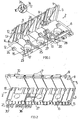
- the adapter strip 2 is formed in its rough outlines as an angle section with a leg 5 and a leg 6 angled to 90 °.
- the adapter strip 2 has in the relevant embodiment, five predetermined breaking points 7, which by opposing one another Grooves are formed on both leg sides, which extend transversely over both the leg 5 and the leg 6.
- openings 8 are formed for the engagement of locking lugs of a Kirsten terminal connection module, wherein in the considered embodiment, seven such openings are provided.
- Two projections 9 arranged at the longitudinal ends of the leg 5 serve as lateral fixing stops for the module.
- the two locking elements 10 are attached, which are connected by connecting webs 11 elastically connected to the leg 5.
- the two locking elements 10 each have at one end a locking lug 12.
- the locking lug 12 is formed stepwise with a first stage 34 and a second stage 35.
- In the grid spacing of the predetermined breaking points further webs 13 are mounted in triangular form on the leg 5 on the outside. Some of these webs have a stop lug 14 at a free triangle corner.
- the leg 6 is provided at its free, the angled opposite longitudinal edge with a chamfer 15, which carries a numbering inscription. From the leg 6 are outside the outside of three dome 16 with a bottom opening 17 before.
- the leg 6 has, at its longitudinal edge facing the leg 5, recesses 18 for engagement of a lug on the housing of a terminal connection module which can be plugged onto the adapter strip.
- recesses 18 When separating the strip at a predetermined breaking point, further such recesses 18 open on two sides arise.
- hook-shaped connecting elements 23 are provided on the leg 6 on the outside at the free longitudinal edge in the relevant embodiment. Further such hook connecting elements 24 are arranged between the free longitudinal edge and the bend in a row parallel to the longitudinal edge or the bend.
- One of the hook connection elements 23 and one of the hook connection elements 24 has in each case an additional hook part 25 or 26, which protrudes in the longitudinal direction of the adapter strip.
- the hook parts opposite an elastic, curved locking lip 27 and a stop 28 are formed.
- the free end of the bent latching lip 27 projects into an opening 36 formed in the leg 6.
- leg 6 has numerous depressions to avoid accumulation of material.
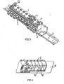
- the adapter bar 2 can be both parallel and transverse to the longitudinal direction of a DIN rail 3 'attach.
- the hook connection elements 23 engage behind a hat rim 29 of the hat profile when the adapter strip is tilted slightly onto the top-hat rail 3 'and is displaced transversely thereto.
- the stop lugs 14 of the webs 13 come to rest against the edge surface of the hat brim 30 and the webs 13 sit on the hat brim 30.
- a transverse displacement of the adapter strip 2 under release of the locking elements 10 from the hooking position is excluded by the stop lugs 14.
- the locking elements 10 are tilted by exerting a compressive force on the locking lug 12 opposite end of the lever bending the connecting webs 11 and thereby brought the locking lug 12 from the Verhakungseingriff with the brim 30.
- the adapter strip 2 can now tilt back again and remove the hooking elements 23 from the top-hat rail 3 'by releasing the entanglements.
- the hook parts 25 and 26, the curved locking lip 27 and the stop 28 are used, as is made Fig. 4 evident.
- the hook parts 25 and 26 engage over the brim 30 of the hat profile rail 3 '. After a rotation of the bar then engages the lip 27 at the hat brim 29 a.
- the elastic locking lip 27 can be bent by an engaging into the opening 36 tool.
- a plurality of adapter strips 2 and 2 ' can be strung together to form a longer terminal strip on the DIN rail 3 and on the juxtaposed adapter strips Klemman gleichrucnmodule 1 and 1' plugged. by completing the Klemman gleichrucnmodule flush with the longitudinal end of the adapter bar, they are also within the longer terminal block directly to each other and can be electrically connected to each other over this case provided standard bridges.
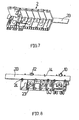
- FIG. 6 Referring to where the adapter strip 2 is shown in connection with a support plate 31.
- the installable in an electrical distribution device carrier plate 31 has holes for a screw connection, wherein fastening screws 32 are guided through the bottom openings 17 in the domes 16.
- FIGS. 7 and 8 show a further mounting option on a installable in a distribution device carrier element, which is formed in the case in question by a flat carrier rail 33 with a rectangular cross-section.
- the hook connecting elements 24 are used, which engage over the edge of the support rail 33. Because of the greater thickness of the rail 33 relative to the crown thickness of the cap profile rail 3 ', the lugs 12 engage with their step 34.
Claims (15)
- Adaptateur pour l'installation de modules de connexion (1) dans des dispositifs de distribution électrique, ledit adaptateur (2) comprenant des moyens pour la liaison avec au moins un module (1) de ce type ainsi que des moyens pour la liaison en avec un rail porteur à profil en chapeau (3), lesquels comportent des éléments en crochet qui s'enclenchent de façon élastique sur les bordures longitudinales mutuellement opposées du rail porteur à profil en chapeau (3),
caractérisé en ce que l'adaptateur est réalisé comme une barrette adaptatrice (2) sous la forme d'un profilé en équerre allongé, et en ce qu'il est prévu des éléments en crochet à enclenchement élastique (10, 12, 24-27) pour l'enclenchement de la barrette adaptatrice (2) sur les bordures longitudinales du rail porteur à profil en chapeau (3) à la fois parallèlement et également transversalement au rail porteur à profilé en chapeau (3). - Adaptateur selon la revendication 1,
caractérisé en ce que l'adaptateur (2) comprend en outre des moyens pour la liaison sélective avec au moins un élément porteur (31, 33) différent du rail porteur à profil en chapeau (3) et utilisé dans des dispositifs distributeurs. - Adaptateur selon la revendication 2,
caractérisé en ce que l'autre élément porteur est un rail porteur (33) ou une plaque porteuse (31). - Adaptateur selon la revendication 3,
caractérisé en ce que les moyens de liaison comportent des coupoles (16) qui dépassent de l'adaptateur (2), avec une ouverture de fond (17) pour une liaison vissée de l'adaptateur (2) avec la plaque porteuse (31). - Adaptateur selon l'une des revendications 1 à 4,
caractérisé en ce que les moyens de liaison comprennent des éléments de liaison (10, 12 ; 23, 25 ; 24, 26) qui sont utilisables dans le cadre de la liaison de l'adaptateur (2) avec différents éléments porteurs (3 ; 33) et/ou avec un élément porteur (3) dans différents agencements vis-à-vis de l'élément porteur (3). - Adaptateur selon l'une des revendications 1 à 5,
caractérisé en ce que la barrette adaptatrice (2) est réalisée pour la formation d'une barrette de connecteurs à bornes qui comprend au moins un module de barrette de connexion (1, 1'). - Adaptateur selon la revendication 6,
caractérisé en ce que la barrette adaptatrice (2) comprend des emplacements de rupture de consigne (7) pour adapter la longueur de la barrette à des modules de barrettes de connexion (1') de longueurs différentes. - Adaptateur selon l'une des revendications 4 à 7,
caractérisé en ce que les coupoles (16) sont reliées à une branche (6) du profil en équerre, et les éléments en crochets à enclenchement élastique (10, 12) sont reliés à une autre branche (5). - Adaptateur selon la revendication 8,
caractérisé en ce que les coupoles (16) sont agencées sur la ligne médiane longitudinale de la branche concernée (6). - Adaptateur selon la revendication 8 ou 9,
caractérisé en ce que les éléments en crochet à enclenchement élastique (10, 12) sont réalisés à la manière d'un levier basculant avec un ergot d'enclenchement (12), qui engage le rail porteur (3 ; 33) par l'arrière, sur une extrémité du bras de levier. - Adaptateur selon la revendication 10,
caractérisé en ce que l'ergot d'enclenchement (12) formé à l'extrémité du bras de levier est réalisé en forme de gradins en vue de l'adaptation à des rails porteurs (3 ; 33) d'épaisseurs différentes. - Adaptateur selon l'une des revendications 1 à 11,
caractérisé en ce qu'il est prévu des butées (14) qui empêchent un déplacement de la barrette adaptatrice (2) transversalement au rail porteur (3 ; 33) avec détachement de la liaison à enclenchement par les éléments en crochets à enclenchement élastique (12, 10) à l'encontre de la direction d'enclenchement. - Adaptateur selon l'une des revendications 1 à 12,
caractérisé en ce que, pour la liaison de la barrette adaptatrice (2) en position transversale avec le rail porteur (3'), il est prévu une lèvre d'enclenchement (27) et une ouverture (36) est formée dans la barrette adaptatrice (2) pour introduire un outil afin de détacher la liaison enclenchée, par déformation de la lèvre d'enclenchement (27). - Adaptateur selon la revendication 13,
caractérisé en ce qu'une extrémité libre de la lèvre d'enclenchement (27) pénètre dans l'ouverture (36). - Adaptateur selon l'une des revendications 7 à 14,
caractérisé en ce que la barrette adaptatrice se raccorde à au moins une extrémité longitudinale en affleurement avec le module de barrette de connexion (1).
Applications Claiming Priority (2)
| Application Number | Priority Date | Filing Date | Title |
|---|---|---|---|
| DE10228418 | 2002-06-25 | ||
| DE2002128418 DE10228418A1 (de) | 2002-06-25 | 2002-06-25 | Adapter für die Installation von Anschlussleistenmodulen in elektrischen Verteilereinrichtungen |
Publications (2)
| Publication Number | Publication Date |
|---|---|
| EP1376793A1 EP1376793A1 (fr) | 2004-01-02 |
| EP1376793B1 true EP1376793B1 (fr) | 2010-04-28 |
Family
ID=29716648
Family Applications (1)
| Application Number | Title | Priority Date | Filing Date |
|---|---|---|---|
| EP20030013689 Expired - Fee Related EP1376793B1 (fr) | 2002-06-25 | 2003-06-17 | Adaptateur pour l'installation de blocs de connection dans des dispositifs de distribution électrique |
Country Status (3)
| Country | Link |
|---|---|
| EP (1) | EP1376793B1 (fr) |
| DE (2) | DE10228418A1 (fr) |
| ES (1) | ES2343173T3 (fr) |
Families Citing this family (3)
| Publication number | Priority date | Publication date | Assignee | Title |
|---|---|---|---|---|
| DE102012014975A1 (de) * | 2012-07-25 | 2014-05-15 | Friedrich Lütze GmbH | Montagesystem für die Anordnung von beispielsweise elektrischen Einrichtungen insbesondere in Schaltschränken |
| DE202017106054U1 (de) | 2017-10-05 | 2019-01-10 | Wago Verwaltungsgesellschaft Mbh | Befestigungseinrichtung zur Befestigung eines Elektrobauteils an einer Tragschiene der Installationstechnik |
| DE202017106653U1 (de) | 2017-11-03 | 2019-02-05 | Weidmüller Interface GmbH & Co. KG | Anordnung mit einer Tragschiene und darauf aneinandergereihten Gehäusen |
Family Cites Families (7)
| Publication number | Priority date | Publication date | Assignee | Title |
|---|---|---|---|---|
| FR2118911B1 (fr) * | 1970-12-23 | 1974-06-07 | Bassani Spa | |
| DE3800809C2 (de) * | 1988-01-14 | 1999-06-02 | Efen Elektrotech Fab | Geräteträgersystem für Stromsammelschienen |
| DE9301558U1 (fr) * | 1993-02-04 | 1993-03-25 | Siemens Ag, 8000 Muenchen, De | |
| DE29706755U1 (de) * | 1997-04-15 | 1997-06-05 | Rehau Ag & Co | Montagevorrichtung |
| DE19906571C2 (de) * | 1999-02-17 | 2001-02-01 | Kaiser Gmbh & Co | Montageplatte für Funktionselemente |
| DE19945817C2 (de) * | 1999-09-20 | 2001-09-13 | Hager Electro Gmbh | Sammelanschlußleiste |
| DE10013111B4 (de) * | 2000-03-17 | 2006-11-02 | Aeg Niederspannungstechnik Gmbh & Co Kg | Adapterplatte und System zur Anbringung eines Bauelementes auf eine Montageunterlage |
-
2002
- 2002-06-25 DE DE2002128418 patent/DE10228418A1/de not_active Withdrawn
-
2003
- 2003-06-17 EP EP20030013689 patent/EP1376793B1/fr not_active Expired - Fee Related
- 2003-06-17 ES ES03013689T patent/ES2343173T3/es not_active Expired - Lifetime
- 2003-06-17 DE DE50312654T patent/DE50312654D1/de not_active Expired - Lifetime
Also Published As
| Publication number | Publication date |
|---|---|
| EP1376793A1 (fr) | 2004-01-02 |
| ES2343173T3 (es) | 2010-07-26 |
| DE50312654D1 (de) | 2010-06-10 |
| DE10228418A1 (de) | 2004-01-22 |
Similar Documents
| Publication | Publication Date | Title |
|---|---|---|
| DE10315668B4 (de) | Anschlußklemme | |
| EP2400611B1 (fr) | Tableau de distribution électrique | |
| EP3284139B1 (fr) | Borne à ressort | |
| EP1186081A1 (fr) | Plaque d'adaptation et systeme pour monter un composant sur un support de montage | |
| DE202013104785U1 (de) | Reihenbausteinanordnung mit einem Energiebussystem | |
| EP0010251B1 (fr) | Dispositif pour la fixation d'appareils d'installation | |
| DE102012206597B4 (de) | Sammelschienenadapter | |
| DE202017100907U1 (de) | Klemme | |
| EP3257121A1 (fr) | Ensemble de plusieurs pieds encliquetables pour module et module | |
| WO2008119651A1 (fr) | Fixation par encliquetage pour fixer un boîtier | |
| DE2748065A1 (de) | Steckeranordnung und befestigungsmittel sowie gehaeuse hierfuer | |
| DE1765978B1 (de) | Schaltungsblock zum elektrischen verbinden mittels steck verbindungen von elektrischen schaltungselementen | |
| EP0221201A1 (fr) | Boîtier pour circuits électriques et électroniques | |
| EP2858186A1 (fr) | Adaptateur de barre omnibus | |
| EP1376793B1 (fr) | Adaptateur pour l'installation de blocs de connection dans des dispositifs de distribution électrique | |
| EP1520330A1 (fr) | Support pour boitier de modules | |
| DE19860961C1 (de) | Elektrisches Gerät mit einer Verbindungseinrichtung zur Verbindung mit einem zweiten elektrischen Gerät | |
| DE102005047045B3 (de) | Anschlussadapter | |
| EP2544012A1 (fr) | Dispositif de connexion pour un compteur d'électricité | |
| EP1580854A1 (fr) | Dispositif porte-étiquette pour armoire électrique | |
| DE4305844C2 (de) | Steckverbinder | |
| DE19846577C2 (de) | Elektrisches Gerät mit einem Verbindungsclip und einer Verbindungsclipaufnahme zur Verbindung mit einem zweiten elektrischen Gerät | |
| DE102012206599B4 (de) | Sammelschienenadapter mit wenigstens einer Kontaktaufnahme | |
| EP2831970A1 (fr) | Module de système destiné au génie électrique d'immeubles et au génie des systèmes portiers de communication | |
| EP1217693B1 (fr) | Réglette de raccordement |
Legal Events
| Date | Code | Title | Description |
|---|---|---|---|
| PUAI | Public reference made under article 153(3) epc to a published international application that has entered the european phase |
Free format text: ORIGINAL CODE: 0009012 |
|
| AK | Designated contracting states |
Kind code of ref document: A1 Designated state(s): AT BE BG CH CY CZ DE DK EE ES FI FR GB GR HU IE IT LI LU MC NL PT RO SE SI SK TR |
|
| AX | Request for extension of the european patent |
Extension state: AL LT LV MK |
|
| 17P | Request for examination filed |
Effective date: 20040619 |
|
| AKX | Designation fees paid |
Designated state(s): DE ES FR SE |
|
| 17Q | First examination report despatched |
Effective date: 20090422 |
|
| GRAP | Despatch of communication of intention to grant a patent |
Free format text: ORIGINAL CODE: EPIDOSNIGR1 |
|
| RAP1 | Party data changed (applicant data changed or rights of an application transferred) |
Owner name: HAGER ELECTRO GMBH & CO. KG |
|
| GRAS | Grant fee paid |
Free format text: ORIGINAL CODE: EPIDOSNIGR3 |
|
| GRAA | (expected) grant |
Free format text: ORIGINAL CODE: 0009210 |
|
| AK | Designated contracting states |
Kind code of ref document: B1 Designated state(s): DE ES FR SE |
|
| REF | Corresponds to: |
Ref document number: 50312654 Country of ref document: DE Date of ref document: 20100610 Kind code of ref document: P |
|
| REG | Reference to a national code |
Ref country code: SE Ref legal event code: TRGR |
|
| REG | Reference to a national code |
Ref country code: ES Ref legal event code: FG2A Ref document number: 2343173 Country of ref document: ES Kind code of ref document: T3 |
|
| PLBE | No opposition filed within time limit |
Free format text: ORIGINAL CODE: 0009261 |
|
| STAA | Information on the status of an ep patent application or granted ep patent |
Free format text: STATUS: NO OPPOSITION FILED WITHIN TIME LIMIT |
|
| 26N | No opposition filed |
Effective date: 20110131 |
|
| REG | Reference to a national code |
Ref country code: DE Ref legal event code: R082 Ref document number: 50312654 Country of ref document: DE Representative=s name: PATENTANWAELTE BERNHARDT/WOLFF PARTNERSCHAFT, DE Ref country code: DE Ref legal event code: R082 Ref document number: 50312654 Country of ref document: DE Representative=s name: CABINET NUSS, FR |
|
| REG | Reference to a national code |
Ref country code: DE Ref legal event code: R082 Ref document number: 50312654 Country of ref document: DE Representative=s name: CABINET NUSS, FR |
|
| REG | Reference to a national code |
Ref country code: FR Ref legal event code: PLFP Year of fee payment: 14 |
|
| REG | Reference to a national code |
Ref country code: FR Ref legal event code: PLFP Year of fee payment: 15 |
|
| REG | Reference to a national code |
Ref country code: FR Ref legal event code: PLFP Year of fee payment: 16 |
|
| PGFP | Annual fee paid to national office [announced via postgrant information from national office to epo] |
Ref country code: FR Payment date: 20180626 Year of fee payment: 16 |
|
| PGFP | Annual fee paid to national office [announced via postgrant information from national office to epo] |
Ref country code: SE Payment date: 20180627 Year of fee payment: 16 |
|
| PGFP | Annual fee paid to national office [announced via postgrant information from national office to epo] |
Ref country code: ES Payment date: 20180702 Year of fee payment: 16 Ref country code: DE Payment date: 20180627 Year of fee payment: 16 |
|
| REG | Reference to a national code |
Ref country code: DE Ref legal event code: R119 Ref document number: 50312654 Country of ref document: DE |
|
| REG | Reference to a national code |
Ref country code: SE Ref legal event code: EUG |
|
| PG25 | Lapsed in a contracting state [announced via postgrant information from national office to epo] |
Ref country code: SE Free format text: LAPSE BECAUSE OF NON-PAYMENT OF DUE FEES Effective date: 20190618 |
|
| PG25 | Lapsed in a contracting state [announced via postgrant information from national office to epo] |
Ref country code: DE Free format text: LAPSE BECAUSE OF NON-PAYMENT OF DUE FEES Effective date: 20200101 |
|
| PG25 | Lapsed in a contracting state [announced via postgrant information from national office to epo] |
Ref country code: FR Free format text: LAPSE BECAUSE OF NON-PAYMENT OF DUE FEES Effective date: 20190630 |
|
| REG | Reference to a national code |
Ref country code: ES Ref legal event code: FD2A Effective date: 20201028 |
|
| PG25 | Lapsed in a contracting state [announced via postgrant information from national office to epo] |
Ref country code: ES Free format text: LAPSE BECAUSE OF NON-PAYMENT OF DUE FEES Effective date: 20190618 |