EP1662151B1 - Hydraulic drive apparatus - Google Patents
Hydraulic drive apparatus Download PDFInfo
- Publication number
- EP1662151B1 EP1662151B1 EP04771548A EP04771548A EP1662151B1 EP 1662151 B1 EP1662151 B1 EP 1662151B1 EP 04771548 A EP04771548 A EP 04771548A EP 04771548 A EP04771548 A EP 04771548A EP 1662151 B1 EP1662151 B1 EP 1662151B1
- Authority
- EP
- European Patent Office
- Prior art keywords
- cylinder
- arm
- hydraulic
- hydraulic cylinder
- boom
- Prior art date
- Legal status (The legal status is an assumption and is not a legal conclusion. Google has not performed a legal analysis and makes no representation as to the accuracy of the status listed.)
- Expired - Fee Related
Links
Images


Classifications
-
- F—MECHANICAL ENGINEERING; LIGHTING; HEATING; WEAPONS; BLASTING
- F15—FLUID-PRESSURE ACTUATORS; HYDRAULICS OR PNEUMATICS IN GENERAL
- F15B—SYSTEMS ACTING BY MEANS OF FLUIDS IN GENERAL; FLUID-PRESSURE ACTUATORS, e.g. SERVOMOTORS; DETAILS OF FLUID-PRESSURE SYSTEMS, NOT OTHERWISE PROVIDED FOR
- F15B11/00—Servomotor systems without provision for follow-up action; Circuits therefor
- F15B11/02—Systems essentially incorporating special features for controlling the speed or actuating force of an output member
- F15B11/024—Systems essentially incorporating special features for controlling the speed or actuating force of an output member by means of differential connection of the servomotor lines, e.g. regenerative circuits
-
- E—FIXED CONSTRUCTIONS
- E02—HYDRAULIC ENGINEERING; FOUNDATIONS; SOIL SHIFTING
- E02F—DREDGING; SOIL-SHIFTING
- E02F9/00—Component parts of dredgers or soil-shifting machines, not restricted to one of the kinds covered by groups E02F3/00 - E02F7/00
- E02F9/20—Drives; Control devices
-
- E—FIXED CONSTRUCTIONS
- E02—HYDRAULIC ENGINEERING; FOUNDATIONS; SOIL SHIFTING
- E02F—DREDGING; SOIL-SHIFTING
- E02F9/00—Component parts of dredgers or soil-shifting machines, not restricted to one of the kinds covered by groups E02F3/00 - E02F7/00
- E02F9/20—Drives; Control devices
- E02F9/22—Hydraulic or pneumatic drives
- E02F9/2221—Control of flow rate; Load sensing arrangements
- E02F9/2225—Control of flow rate; Load sensing arrangements using pressure-compensating valves
-
- E—FIXED CONSTRUCTIONS
- E02—HYDRAULIC ENGINEERING; FOUNDATIONS; SOIL SHIFTING
- E02F—DREDGING; SOIL-SHIFTING
- E02F9/00—Component parts of dredgers or soil-shifting machines, not restricted to one of the kinds covered by groups E02F3/00 - E02F7/00
- E02F9/20—Drives; Control devices
- E02F9/22—Hydraulic or pneumatic drives
- E02F9/2278—Hydraulic circuits
- E02F9/2296—Systems with a variable displacement pump
-
- F—MECHANICAL ENGINEERING; LIGHTING; HEATING; WEAPONS; BLASTING
- F15—FLUID-PRESSURE ACTUATORS; HYDRAULICS OR PNEUMATICS IN GENERAL
- F15B—SYSTEMS ACTING BY MEANS OF FLUIDS IN GENERAL; FLUID-PRESSURE ACTUATORS, e.g. SERVOMOTORS; DETAILS OF FLUID-PRESSURE SYSTEMS, NOT OTHERWISE PROVIDED FOR
- F15B11/00—Servomotor systems without provision for follow-up action; Circuits therefor
- F15B11/16—Servomotor systems without provision for follow-up action; Circuits therefor with two or more servomotors
-
- F—MECHANICAL ENGINEERING; LIGHTING; HEATING; WEAPONS; BLASTING
- F15—FLUID-PRESSURE ACTUATORS; HYDRAULICS OR PNEUMATICS IN GENERAL
- F15B—SYSTEMS ACTING BY MEANS OF FLUIDS IN GENERAL; FLUID-PRESSURE ACTUATORS, e.g. SERVOMOTORS; DETAILS OF FLUID-PRESSURE SYSTEMS, NOT OTHERWISE PROVIDED FOR
- F15B21/00—Common features of fluid actuator systems; Fluid-pressure actuator systems or details thereof, not covered by any other group of this subclass
- F15B21/14—Energy-recuperation means
-
- F—MECHANICAL ENGINEERING; LIGHTING; HEATING; WEAPONS; BLASTING
- F15—FLUID-PRESSURE ACTUATORS; HYDRAULICS OR PNEUMATICS IN GENERAL
- F15B—SYSTEMS ACTING BY MEANS OF FLUIDS IN GENERAL; FLUID-PRESSURE ACTUATORS, e.g. SERVOMOTORS; DETAILS OF FLUID-PRESSURE SYSTEMS, NOT OTHERWISE PROVIDED FOR
- F15B2211/00—Circuits for servomotor systems
- F15B2211/20—Fluid pressure source, e.g. accumulator or variable axial piston pump
- F15B2211/205—Systems with pumps
- F15B2211/20507—Type of prime mover
- F15B2211/20523—Internal combustion engine
-
- F—MECHANICAL ENGINEERING; LIGHTING; HEATING; WEAPONS; BLASTING
- F15—FLUID-PRESSURE ACTUATORS; HYDRAULICS OR PNEUMATICS IN GENERAL
- F15B—SYSTEMS ACTING BY MEANS OF FLUIDS IN GENERAL; FLUID-PRESSURE ACTUATORS, e.g. SERVOMOTORS; DETAILS OF FLUID-PRESSURE SYSTEMS, NOT OTHERWISE PROVIDED FOR
- F15B2211/00—Circuits for servomotor systems
- F15B2211/20—Fluid pressure source, e.g. accumulator or variable axial piston pump
- F15B2211/205—Systems with pumps
- F15B2211/2053—Type of pump
- F15B2211/20546—Type of pump variable capacity
-
- F—MECHANICAL ENGINEERING; LIGHTING; HEATING; WEAPONS; BLASTING
- F15—FLUID-PRESSURE ACTUATORS; HYDRAULICS OR PNEUMATICS IN GENERAL
- F15B—SYSTEMS ACTING BY MEANS OF FLUIDS IN GENERAL; FLUID-PRESSURE ACTUATORS, e.g. SERVOMOTORS; DETAILS OF FLUID-PRESSURE SYSTEMS, NOT OTHERWISE PROVIDED FOR
- F15B2211/00—Circuits for servomotor systems
- F15B2211/20—Fluid pressure source, e.g. accumulator or variable axial piston pump
- F15B2211/205—Systems with pumps
- F15B2211/20576—Systems with pumps with multiple pumps
-
- F—MECHANICAL ENGINEERING; LIGHTING; HEATING; WEAPONS; BLASTING
- F15—FLUID-PRESSURE ACTUATORS; HYDRAULICS OR PNEUMATICS IN GENERAL
- F15B—SYSTEMS ACTING BY MEANS OF FLUIDS IN GENERAL; FLUID-PRESSURE ACTUATORS, e.g. SERVOMOTORS; DETAILS OF FLUID-PRESSURE SYSTEMS, NOT OTHERWISE PROVIDED FOR
- F15B2211/00—Circuits for servomotor systems
- F15B2211/30—Directional control
- F15B2211/305—Directional control characterised by the type of valves
- F15B2211/30525—Directional control valves, e.g. 4/3-directional control valve
-
- F—MECHANICAL ENGINEERING; LIGHTING; HEATING; WEAPONS; BLASTING
- F15—FLUID-PRESSURE ACTUATORS; HYDRAULICS OR PNEUMATICS IN GENERAL
- F15B—SYSTEMS ACTING BY MEANS OF FLUIDS IN GENERAL; FLUID-PRESSURE ACTUATORS, e.g. SERVOMOTORS; DETAILS OF FLUID-PRESSURE SYSTEMS, NOT OTHERWISE PROVIDED FOR
- F15B2211/00—Circuits for servomotor systems
- F15B2211/30—Directional control
- F15B2211/305—Directional control characterised by the type of valves
- F15B2211/3056—Assemblies of multiple valves
- F15B2211/30565—Assemblies of multiple valves having multiple valves for a single output member, e.g. for creating higher valve function by use of multiple valves like two 2/2-valves replacing a 5/3-valve
- F15B2211/3058—Assemblies of multiple valves having multiple valves for a single output member, e.g. for creating higher valve function by use of multiple valves like two 2/2-valves replacing a 5/3-valve having additional valves for interconnecting the fluid chambers of a double-acting actuator, e.g. for regeneration mode or for floating mode
-
- F—MECHANICAL ENGINEERING; LIGHTING; HEATING; WEAPONS; BLASTING
- F15—FLUID-PRESSURE ACTUATORS; HYDRAULICS OR PNEUMATICS IN GENERAL
- F15B—SYSTEMS ACTING BY MEANS OF FLUIDS IN GENERAL; FLUID-PRESSURE ACTUATORS, e.g. SERVOMOTORS; DETAILS OF FLUID-PRESSURE SYSTEMS, NOT OTHERWISE PROVIDED FOR
- F15B2211/00—Circuits for servomotor systems
- F15B2211/30—Directional control
- F15B2211/31—Directional control characterised by the positions of the valve element
- F15B2211/3105—Neutral or centre positions
- F15B2211/3116—Neutral or centre positions the pump port being open in the centre position, e.g. so-called open centre
-
- F—MECHANICAL ENGINEERING; LIGHTING; HEATING; WEAPONS; BLASTING
- F15—FLUID-PRESSURE ACTUATORS; HYDRAULICS OR PNEUMATICS IN GENERAL
- F15B—SYSTEMS ACTING BY MEANS OF FLUIDS IN GENERAL; FLUID-PRESSURE ACTUATORS, e.g. SERVOMOTORS; DETAILS OF FLUID-PRESSURE SYSTEMS, NOT OTHERWISE PROVIDED FOR
- F15B2211/00—Circuits for servomotor systems
- F15B2211/30—Directional control
- F15B2211/315—Directional control characterised by the connections of the valve or valves in the circuit
- F15B2211/3157—Directional control characterised by the connections of the valve or valves in the circuit being connected to a pressure source, an output member and a return line
- F15B2211/31576—Directional control characterised by the connections of the valve or valves in the circuit being connected to a pressure source, an output member and a return line having a single pressure source and a single output member
-
- F—MECHANICAL ENGINEERING; LIGHTING; HEATING; WEAPONS; BLASTING
- F15—FLUID-PRESSURE ACTUATORS; HYDRAULICS OR PNEUMATICS IN GENERAL
- F15B—SYSTEMS ACTING BY MEANS OF FLUIDS IN GENERAL; FLUID-PRESSURE ACTUATORS, e.g. SERVOMOTORS; DETAILS OF FLUID-PRESSURE SYSTEMS, NOT OTHERWISE PROVIDED FOR
- F15B2211/00—Circuits for servomotor systems
- F15B2211/30—Directional control
- F15B2211/32—Directional control characterised by the type of actuation
- F15B2211/329—Directional control characterised by the type of actuation actuated by fluid pressure
-
- F—MECHANICAL ENGINEERING; LIGHTING; HEATING; WEAPONS; BLASTING
- F15—FLUID-PRESSURE ACTUATORS; HYDRAULICS OR PNEUMATICS IN GENERAL
- F15B—SYSTEMS ACTING BY MEANS OF FLUIDS IN GENERAL; FLUID-PRESSURE ACTUATORS, e.g. SERVOMOTORS; DETAILS OF FLUID-PRESSURE SYSTEMS, NOT OTHERWISE PROVIDED FOR
- F15B2211/00—Circuits for servomotor systems
- F15B2211/40—Flow control
- F15B2211/405—Flow control characterised by the type of flow control means or valve
- F15B2211/40507—Flow control characterised by the type of flow control means or valve with constant throttles or orifices
-
- F—MECHANICAL ENGINEERING; LIGHTING; HEATING; WEAPONS; BLASTING
- F15—FLUID-PRESSURE ACTUATORS; HYDRAULICS OR PNEUMATICS IN GENERAL
- F15B—SYSTEMS ACTING BY MEANS OF FLUIDS IN GENERAL; FLUID-PRESSURE ACTUATORS, e.g. SERVOMOTORS; DETAILS OF FLUID-PRESSURE SYSTEMS, NOT OTHERWISE PROVIDED FOR
- F15B2211/00—Circuits for servomotor systems
- F15B2211/40—Flow control
- F15B2211/405—Flow control characterised by the type of flow control means or valve
- F15B2211/40515—Flow control characterised by the type of flow control means or valve with variable throttles or orifices
-
- F—MECHANICAL ENGINEERING; LIGHTING; HEATING; WEAPONS; BLASTING
- F15—FLUID-PRESSURE ACTUATORS; HYDRAULICS OR PNEUMATICS IN GENERAL
- F15B—SYSTEMS ACTING BY MEANS OF FLUIDS IN GENERAL; FLUID-PRESSURE ACTUATORS, e.g. SERVOMOTORS; DETAILS OF FLUID-PRESSURE SYSTEMS, NOT OTHERWISE PROVIDED FOR
- F15B2211/00—Circuits for servomotor systems
- F15B2211/40—Flow control
- F15B2211/415—Flow control characterised by the connections of the flow control means in the circuit
- F15B2211/41527—Flow control characterised by the connections of the flow control means in the circuit being connected to an output member and a directional control valve
- F15B2211/41545—Flow control characterised by the connections of the flow control means in the circuit being connected to an output member and a directional control valve being connected to multiple output members
-
- F—MECHANICAL ENGINEERING; LIGHTING; HEATING; WEAPONS; BLASTING
- F15—FLUID-PRESSURE ACTUATORS; HYDRAULICS OR PNEUMATICS IN GENERAL
- F15B—SYSTEMS ACTING BY MEANS OF FLUIDS IN GENERAL; FLUID-PRESSURE ACTUATORS, e.g. SERVOMOTORS; DETAILS OF FLUID-PRESSURE SYSTEMS, NOT OTHERWISE PROVIDED FOR
- F15B2211/00—Circuits for servomotor systems
- F15B2211/40—Flow control
- F15B2211/42—Flow control characterised by the type of actuation
- F15B2211/428—Flow control characterised by the type of actuation actuated by fluid pressure
-
- F—MECHANICAL ENGINEERING; LIGHTING; HEATING; WEAPONS; BLASTING
- F15—FLUID-PRESSURE ACTUATORS; HYDRAULICS OR PNEUMATICS IN GENERAL
- F15B—SYSTEMS ACTING BY MEANS OF FLUIDS IN GENERAL; FLUID-PRESSURE ACTUATORS, e.g. SERVOMOTORS; DETAILS OF FLUID-PRESSURE SYSTEMS, NOT OTHERWISE PROVIDED FOR
- F15B2211/00—Circuits for servomotor systems
- F15B2211/60—Circuit components or control therefor
- F15B2211/635—Circuits providing pilot pressure to pilot pressure-controlled fluid circuit elements
- F15B2211/6355—Circuits providing pilot pressure to pilot pressure-controlled fluid circuit elements having valve means
-
- F—MECHANICAL ENGINEERING; LIGHTING; HEATING; WEAPONS; BLASTING
- F15—FLUID-PRESSURE ACTUATORS; HYDRAULICS OR PNEUMATICS IN GENERAL
- F15B—SYSTEMS ACTING BY MEANS OF FLUIDS IN GENERAL; FLUID-PRESSURE ACTUATORS, e.g. SERVOMOTORS; DETAILS OF FLUID-PRESSURE SYSTEMS, NOT OTHERWISE PROVIDED FOR
- F15B2211/00—Circuits for servomotor systems
- F15B2211/70—Output members, e.g. hydraulic motors or cylinders or control therefor
- F15B2211/71—Multiple output members, e.g. multiple hydraulic motors or cylinders
- F15B2211/7114—Multiple output members, e.g. multiple hydraulic motors or cylinders with direct connection between the chambers of different actuators
-
- F—MECHANICAL ENGINEERING; LIGHTING; HEATING; WEAPONS; BLASTING
- F15—FLUID-PRESSURE ACTUATORS; HYDRAULICS OR PNEUMATICS IN GENERAL
- F15B—SYSTEMS ACTING BY MEANS OF FLUIDS IN GENERAL; FLUID-PRESSURE ACTUATORS, e.g. SERVOMOTORS; DETAILS OF FLUID-PRESSURE SYSTEMS, NOT OTHERWISE PROVIDED FOR
- F15B2211/00—Circuits for servomotor systems
- F15B2211/80—Other types of control related to particular problems or conditions
- F15B2211/88—Control measures for saving energy
Abstract
Description
- This invention relates to a hydraulic drive systemmounted on a construction machine such as a hydraulic excavator to permit a combined operation of plural hydraulic cylinders.
- There have conventionally been proposed hydraulic control systems, each of which is mounted on a hydraulic excavator and has a main hydraulic pump and a boom cylinder and arm cylinder as a first hydraulic cylinder and second hydraulic cylinder driven by pressure oil delivered from the main hydraulic pump. This conventional art is provided with a directional control valve for a boom as a first directional control valve for controlling a flow of pressure oil to be fed from the main hydraulic pump to the boom cylinder, a directional control valve for an arm as a second directional control valve for controlling a flow of pressure oil to be fed from the main hydraulic pump to the arm cylinder, a boom control device as a first control device for selectively controlling the directional control valve for the boom, and an arm control device as a second control device for performing a switching control of the directional control valve for the arm, and is also provided with a communication control means for communicating a rod chamber of the boom cylinder and a bottom chamber of the arm cylinder with each other when a bottom pressure of the arm cylinder has increased to a high pressure equal to or higher than a predetermined pressure. (see, for example,
JP-A-2002-339907 - When the bottom pressure of an arm cylinder has become high as a result of digging work or the like of earth in a combined boom-arm operation performed by feeding pressure oil to both of a bottom chamber of a boom cylinder and a bottom chamber of the arm cylinder, the above-described conventional art can effectively use pressure oil in a rod chamber of the boom cylinder, which was conventionally drained, for an acceleration of the arm cylinder in its extending direction, and can realize an improvement in the efficiency of the work.
- In some work, however, the bottom pressure of the arm cylinder may not become high upon performing a combined boom-arm operation as in work involving a crowding operation of a bucket in the air. Even in such work, it is desired to realize an acceleration of the arm cylinder, that is, a second hydraulic cylinder.
- With a view to meeting the above-describe desire, the present invention has as an object the provision of a hydraulic drive system which, in a combined operation to be performed by feeding pressure oil to both of bottomcombers of a first hydraulic cylinder and second hydraulic cylinder, can effectively use pressure oil in a rod chamber of the first hydraulic cylinder, which was conventionally drained into a reservoir, irrespective of the level of a bottompressure in the second hydraulic cylinder.
- To achieve the above-described object, the present invention is characterized in that, in a hydraulic drive system provided with a main hydraulic pump, a first hydraulic cylinder and second hydraulic cylinder driven by pressure oil delivered from the main hydraulic pump, a first directional control valve for controlling a flow of pressure oil to be fed from the main hydraulic pump to the first hydraulic cylinder, a second directional control valve for controlling a flow of pressure oil to be fed from the main hydraulic pump to the second hydraulic cylinder, a first control device for selectively controlling the first directional control valve, and a second control device for selectively controlling the second directional control valve, the hydraulic drive system is provided with a communication control means for communicating a rod chamber of the first hydraulic cylinder and a bottom chamber of the second hydraulic cylinder with each other when a stroke of the second control device has increased to at least a predetermined amount.
- According to the present invention constructed as described above, when the stroke of the second control device has increased to at least the predetermined amount upon performing a combined operation of these first hydraulic cylinder and second hydraulic cylinder by controlling the first control device and second control device to switch the first directional control valve and second directional control valve and feeding pressure oil from the main hydraulic pump to the bottom chambers of the first hydraulic cylinder and second hydraulic cylinder via the first directional control valve and second directional control valve, respectively, the communication control means is actuated to feed the pressure oil in a rod chamber of the first hydraulic cylinder to the bottom chamber of the second hydraulic cylinder. Described specifically, the pressure oil delivered from the main hydraulic pump and fed via the second directional control valve and the pressure oil fed from the rod chamber of the first hydraulic cylinder are combined and fed to the bottom chamber of the second hydraulic cylinder, and as a result, an acceleration can be achieved in the extending direction of the second hydraulic cylinder irrespective of the level of pressure oil in the bottom chamber of the second hydraulic cylinder. As described above, the pressure oil in the rod chamber of the first hydraulic cylinder, which was conventionally drained into the reservoir, can be effectively used for the selective acceleration of the second hydraulic cylinder.
- The present invention can also be characterized in that in the above-described invention, the communication control means may comprise a communication line capable of communicating the rod chamber of the first hydraulic cylinder and the bottom chamber of the second hydraulic cylinder with each other, a check valve arranged on the communication line to prevent a flow of pressure oil from the bottom chamber of the second hydraulic cylinder toward the rod chamber of the first hydraulic cylinder, and a selector valve for feeding pressure oil in the rod chamber of the first hydraulic cylinder to the bottom chamber of the second hydraulic cylinder via the communication line.
- According to the present invention constructed as described immediately above, when the stroke of the second control device has increased to at least the predetermined amount upon performing a combined operation of these first hydraulic cylinder and second hydraulic cylinder by feeding pressure oil from the main hydraulic pump to the bottom chambers of the first hydraulic cylinder and second hydraulic cylinder, respectively, the selector valve is switched to maintain the communication line in a communicating state, and as a result, the pressure oil in the rod chamber of the first hydraulic cylinder is fed to the bottom chamber of the second hydraulic cylinder via the communication line and check valve. Described specifically, the pressure oil fed to the bottom chamber of the second hydraulic cylinder via the second directional control valve and the pressure oil fed from the rod chamber of the first hydraulic cylinder are combined and fed to the bottom chamber of the second hydraulic cylinder, and as a result, an acceleration can be achieved in the extending direction of the second hydraulic cylinder.
- When the stroke of the second control device is so small that it does not reach the predetermined amount upon performing a combined operation of the first hydraulic cylinder and second hydraulic cylinder as mentioned above, the selector valve is held to communicate the communication line with the reservoir, and a result, the pressure oil in the rod chamber of the first hydraulic cylinder is drained into the reservoir. In this case, to the bottom chamber of the second hydraulic cylinder, pressure oil is fed only via the second directional control valve so that no acceleration is achieved in the extending direction of the second hydraulic cylinder.
- The present invention can also be characterized in that in the above-described invention, the selector valve may include a variable restrictor.
- According to the present invention constructed as described immediately above, the opening of the variable restrictor included in the selector valve changes depending upon the stroke of the second control device. Described specifically, when the stroke of the second control device is relatively small although it is equal to or greater than the predetermined amount, the opening of the variable restrictor in the selector valve becomes smaller so that the flow rate of pressure oil from the rod chamber of the first hydraulic cylinder, which is to be fed to the communication line via the variable restrictor, is reduced. When the stroke of the second control device is equal to or greater than the predetermined amount and is relatively large, on the other hand, the opening of the variable restrictor in the selector valve becomes large so that the flow rate of pressure oil from the rod chamber of the first hydraulic cylinder, which is to be fed to the communication line via the variable restrictor, can be increased.
- The present invention can also be characterized that the above-described invention may further comprise a branch line connected at an end thereof to a main line, which connects the first directional control valve and the rod chamber of the first hydraulic cylinder with each other, and at an opposite end thereof to the selector valve.
- According to the present invention constructed as described immediately above, when the stroke of the second control device has increased to at least the predetermined amount upon performing a combined operation of these first hydraulic cylinder and second hydraulic cylinder, the pressure oil in the rod chamber of the first hydraulic cylinder is fed to the bottom chamber of the second hydraulic cylinder from the communication line without going through the first directional control valve. It is, therefore, possible to reduce a pressure loss compared with feeding the pressure oil through the first directional control valve insofar as the diameter of the branch line is set sufficiently large.
- The present invention can also be characterized in that the above-described invention may further comprise a stroke detector for detecting a stroke of the second control device and outputting an electrical signal, and a controller for outputting, responsive to the signal outputted from the stroke detector, a control signal to selectively control the selector valve.
- According to the present invention constructed as described immediately above, when it is detected by the stroke detector that the stroke of the second control device has increased to at least the predetermined amount, the electrical signal outputted from the stroke detector is inputted to the controller. As a result, a control signal for switching the selector valve is outputted from the controller so that the selector valve is switched to maintain the communication line in the communicating state. The pressure oil in the rod chamber of the first hydraulic cylinder is, therefore, fed to the bottom chamber of the second hydraulic cylinder via the communication line and check valve.
- The present invention can also be characterized in that in the above-described invention, the controller may include a function generator for outputting a value which becomes gradually greater as the stroke of the second control device increases.
- According to the present invention constructed as described immediately above, a value which becomes gradually greater as the stroke of the second control device increases is determined at the function generator, and a control signal corresponding to the thus-determined value is outputted from the controller to control the amount of switching of the selector valve. It is, therefore, possible to control the speed of the second hydraulic cylinder which is in a state accelerated corresponding to the stroke of the second control device.
- The present invention can also be characterized in that in the above-described invention, the selector valve may be a pilot-controlled selector valve, and the hydraulic drive system may be provided with an electric-hydraulic converter for outputting a control pressure corresponding to the control signal outputted from the controller and a control line communicating the electric-hydraulic converter and the pilot-controlled selector valve with each other.
- According to the present invention constructed as described immediately above, when a control signal outputted from the controller is fed to the electric-hydraulic converter, a pilot pressure corresponding to the value of the control signal is applied from the electric-hydraulic converter to the control chamber of the pilot-controlled selector valve via the control line so that the amount of switching of the selector valve is controlled depending upon the level of the pilot pressure.
- The present invention can also be characterized in that in the above-described invention, the first hydraulic cylinder and second hydraulic cylinder may comprise a boom cylinder and arm cylinder, respectively, the first directional control valve and second directional control valve may comprise a center-bypass-type, directional control valve for a boom and directional control valve for an arm, respectively, and the first control device and second control device may comprise a boom control device and arm control device, respectively.
- According to the present invention constructed as described immediately above, when the stroke of the arm control device has increased to at least the predetermined amount upon performing a combined operation of the boom cylinder and arm cylinder by controlling the boom control device and arm control device to switch the directional control valve for the boom and the directional control valve for the arm and feeding pressure oil from the main hydraulic pump to the bottom chambers of these boom cylinder and arm cylinder via the directional control valve for the boom and the directional control valve for the arm, that is, upon performing a combined operation of boom raising and arm crowding, the communication control means is actuated such that the pressure oil in the rod chamber of the boom cylinder is fed to the bottom chamber of the arm cylinder. Described specifically, the pressure oil delivered from the main hydraulic pump and fed via the directional control valve for the arm and the pressure oil fed from the rod chamber of the boom cylinder are combined and fed to the bottom chamber of the arm cylinder, and as a result, an acceleration in the extending direction of the arm cylinder, that is, an acceleration in arm crowding can be realized.
- According to the invention constructed as described immediately above, upon performing a combined operation by feeding oil pressure to the bottom chambers of the first hydraulic cylinder and second hydraulic cylinder, respectively, the pressure oil in the rod chamber of the first hydraulic cylinder, which was conventionally drained into the reservoir, can be effectively used depending upon the stroke of the second control device, which controls the second hydraulic cylinder, irrespective of the level of the bottom pressure of the second hydraulic cylinder, and compared with the conventional art, it is thus possible to perform more work with effective use of pressure oil.
-
-
FIG. 1 is a hydraulic circuit diagram showing a first embodiment of the hydraulic drive system according to the present invention. -
FIG. 2 is a characteristic diagram illustrating a relation between an arm pilot pressure and a flow rate through a communication line, which is available in the first embodiment shown inFIG. 1 . -
FIG. 3 is a hydraulic circuit diagram showing a second embodiment of the present invention. -
FIG. 4 is a hydraulic circuit diagram showing a third embodiment of the present invention. -
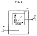
FIG. 5 is a diagram illustrating the construction of an essential part of a controller which the third embodiment shown inFIG. 4 is provided with. - Best modes for carrying out the hydraulic drive system according to the present invention will hereinafter be described based on the drawings.
-
FIG. 1 is a circuit diagram showing the first embodiment of the hydraulic drive system according to the present invention. - Not only the first embodiment shown in
FIG. 1 but also the second and third embodiments to be described subsequently herein are arranged on construction machines, for example, on hydraulic excavators, and each comprises a hydraulic drive system of the center bypass type for driving, for example, aboom cylinder 6 as a first hydraulic cylinder and an arm cylinder 7 as a second hydraulic cylinder. Theboom cylinder 6 is provided with abottom chamber 6a and arod chamber 6b, and the arm cylinder 7 is likewise provided with abottom chamber 7a and arod chamber 7b. - The first embodiment is also provided with an
engine 20, a mainhydraulic pump 21 andpilot pump 22 driven by theengine 20, a first directional control valve for controlling a flow of pressure oil to be fed to theboom cylinder 6, i.e., a center-bypass-typedirectional control valve 23 for the boom, a second directional control valve for controlling a flow of pressure oil to be fed to the arm cylinder 7, i.e., a center-bypass-typedirectional control valve 24 for the arm. Also provided are a first control device for selectively controlling thedirectional control valve 23 for the boom, i.e., aboom control device 25 and a second control device for selectively controlling thedirectional control valve 24 for the arm, i.e., anarm control device 26. -
Lines hydraulic pump 21, thedirectional control valve 24 for the arm is arranged on theline 27, and thedirectional control valve 23 for the boom is arranged on theline 28. - The
directional control valve 23 for the boom and thebottom chamber 6a of theboom cylinder 6 are connected via amain line 29a, while thedirectional control valve 23 for the boom and therod chamber 6b of theboom cylinder 6 are connected via amain line 29b. Thedirectional control valve 24 for the arm and thebottom chamber 7a of the arm cylinder 7 are connected via amain line 30a, while thedirectional control valve 24 for the arm and therod chamber 7b of the arm cylinder 7 are connected via amain line 30b. - The
boom control device 25 andarm control device 26 are composed, for example, of pilot control devices which produce pilotpressures, andareconnectedtothepilotpump22. Further, theboom control device 25 is connected to control chambers of thedirectional control valve 23 for the boom viapilot lines arm control device 26 is connected to control chambers of thedirectional control valve 24 for the arm viapilot lines - This first embodiment is provided with a communication control means for communicating the
rod chamber 6b of theboom cylinder 6, which makes up the first hydraulic cylinder, and thebottom chamber 7a of the arm cylinder 7, which makes up the second hydraulic cylinder, with each other especially when the stroke of the arm control device as the second control device has increased to a predetermined amount S or greater. - As shown by way of example in
FIG. 1 , this communication control means comprises acommunication line 40 capable of communicating therod chamber 6b of theboom cylinder 6 and thebottom chamber 7a of the arm cylinder 7 with each other, acheck valve 41 arranged on thecommunication line 40 to prevent a flow of pressure oil from thebottom chamber 7a of the arm cylinder 7 toward therod chamber 6b of theboom cylinder 6, and aselector valve 52 for feeding pressure fluid in therod chamber 6b of theboom cylinder 6 to thebottom chamber 7a of the arm cylinder 7 via thecommunication line 40 when the stroke of thearm control device 26 has increased to the predetermined amount S or greater. Thisselector valve 52 comprises a pilot control device which is switched by an arm pilot pressure guided via acontrol line 52a connected to thepilot line 26a. - Also arranged are a
line 46 connected at an end thereof to the part of thecommunication line 40 located on an upstream side of thecheck valve 41 and at an opposite end thereof to areservoir 43, and a pilot-controlledcheck valve 47 arranged on theline 46 such that responsive to a predetermined control of the boom control device as the first control device, for example, an operation to feed pressure oil to thepilot line 25b to perform boom lowering, theline 46 is opened. The above-describedpilot line 25b and pilot-controlledcheck valve 47 are connected together by acontrol line 48. - In the first embodiment constructed as described above, combined operations of the
boom cylinder 6 and the arm cylinder 7 are performed as will be described hereinafter. - When the
boom control device 25 is controlled to feed a pilot pressure to thepilot line 25a such that thedirectional control valve 23 for the boom is switched into the left position as shown inFIG. 1 and further, thearm control device 26 is controlled to feed a pilot pressure to thepilot line 26a such that thedirectional control valve 24 for the arm is switched into the left position as shown inFIG. 1 , pressure oil delivered from the mainhydraulic pump 21 is fed to thebottom chamber 6a of theboom cylinder 6 via theline 28, thedirectional control valve 23 for the boom and themain line 29a, and further, the pressure oil delivered from the mainhydraulic pump 21 is also fed to thebottom chamber 7a of the arm cylinder 7 via theline 27, thedirectional control valve 24 for the arm and themain line 30a. As a result, theboom cylinder 6 and arm cylinder 7 are both operated in extending directions to perform a combined operation of boom raising and arm crowding. - During the above-described combined operation, the
pilot line 25b of the boom operating system is not fed with the pilot pressure, and remains under the same pressure as the reservoir pressure. Therefore, thecontrol line 48 takes the reservoir pressure so that the pilot-controlledcheck valve 47 remains in a closed position to prevent communication between thecommunication line 40 and thereservoir 43 via theline 46. - In a state that the stroke of the
arm control device 26 is smaller than the predetermined amount S, the force of an arm pilot pressure corresponding to the is smaller than the spring force of theselector valve 52 , and therefore, thisselector valve 52 is held in the right position shown inFIG. 1 . In this state, therod chamber 6b of theboom cylinder 6 is in communication with thereservoir 43 via themain line 29b, thedirectional control valve 23 for the boom, thereservoir line 42, and theselector valve 52. During an extending operation of theboom cylinder 6, the pressure oil in therod chamber 6b of theboom cylinder 6 is, therefore, returned to thereservoir 43, and the pressure oil in therod chamber 6b is not fed to thecommunication line 40. - When the stroke of the
arm control device 26 increases to the predetermined amount S or greater from such a state as described above, the force produced by an arm pilot pressure guided corresponding to the stroke via thecontrol line 52a becomes greater than the spring force of theselector valve 52 so that theselector valve 52 tends to be switched toward the left position inFIG. 1 . When this state is established, thereservoir line 42 begins to be closed by theselector valve 52 so that a predetermined portion of the pressure oil, which has been guided from therod chamber 6b of theboom cylinder 6 into themain line 29b, thedirectional control valve 23 for the boom and thereservoir line 42, is fed to thecommunication line 40 via thecheck valve 41. As illustrated inFIG. 2 , the flow rate at which the predetermined portion of the pressure oil is fed at this time increases with the arm pilot pressure which corresponds to the stroke of thearm control device 26. It is to be noted that inFIG. 2 , "S" indicates the above-mentioned predetermined stroke and "F" indicates the stroke at the time of a full stroke. The pressure oil fed to thecommunication line 40 is fed to thebottom chamber 7a of the arm cylinder 7 via themain line 30a. Described specifically, the pressure oil delivered from the mainhydraulic pump 21 and fed via thedirectional control valve 24 for the arm and the pressure oil fed from therod chamber 6b of theboom cylinder 6 are combined and fed to thebottom chamber 7a of the arm cylinder 7. As a result, an acceleration of thearm cylinder 6 in the extending direction can be realized. In other words, the operating speed of arm crowding can be rendered faster. - When the
boom control device 25 is controlled to feed a pilot pressure to thepilot line 25b such that thedirectional control valve 23 for the boom is switched into the right position shown inFIG. 1 and further, thearmcontrol device 26 is controlled to feed a pilot pressure to thepilot line 26a such that thedirectional control valve 24 for the arm is switched into the left position, pressure oil delivered from the mainhydraulic pump 21 is fed to therod chamber 6b of theboom cylinder 6 via theline 28, thedirectional control valve 23 for the boom and themain line 29b, and as mentioned above, the pressure oil delivered from the mainhydraulic pump 21 is also fed to thebottom chamber 7a of the arm cylinder 7 via theline 27, thedirectional control valve 24 for the arm and themain line 30a. As a result, theboom cylinder 6 is operated in a retracting direction and the arm cylinder 7 is operated in the extending direction so that a combined operation of boom lowering and arm crowding is performed. - As the pilot pressure is being fed to the
pilot line 25b in the boom operating system during such a combined operation, a control pressure is guided into thecontrol line 48 so that the pilot-controlledcheck valve 47 is operated to open theline 46. As a result, the part of thecommunication line 40 on the upstream side of theselector valve 52 is brought into communication with thereservoir 43. - When the stroke of the
second control device 26 increases to the predetermined amount S or greater, theselector valve 52 tends to be switched toward the left position inFIG. 1 as mentioned above. The part of thecommunication line 40 is, however, in communication with thereservoir 43 via the pilot-controlledcheck valve 47 and theline 46 as mentioned above. Consequently, thebottom chamber 6a of theboom cylinder 6 is brought into a state communicated with thereservoir 43. - In this state, the pressure oil in the
bottom chamber 6a of theboom cylinder 6 is returned to thereservoir 43 via themain line 29a and thedirectional control valve 23 for the boom. The pressure oil in thebottom chamber 6a of theboom cylinder 6 is, therefore, not fed to thebottom chamber 7a of the arm cylinder 7 via thecommunication line 40 so that no acceleration is performed in arm crowding. - Upon performing a combined operation including arm dumping in which pressure oil is fed to the
rod chamber 7b of the arm cylinder 7, thebottom chamber 7a of the arm cylinder 7 is brought into communication with thereservoir 43. No pressure is, therefore, developed in thecommunication line 40 so that no acceleration of the arm cylinder 7 is performed. - In the first embodiment constructed as described above, during a combined operation of boom raising and arm crowding, the pressure oil in the
rod chamber 6a of theboom cylinder 6 can be combined to thebottom chamber 7a of the arm cylinder 7 as a result of a control of thesecond control device 26 irrespective of the level of the bottom pressure in the arm cylinder 7. This makes it possible to effectively use the pressure oil in therod chamber 6a of theboom cylinder 6, the pressure oil having heretofore been simply drained into thereservoir 43, for the acceleration of the arm cylinder 7 and hence, to achieve an improvement in the efficiency of the work. It is possible to improve the efficiency of work, for example, not only in digging work of earth that the pressure in thebottom chamber 7a of the arm cylinder 7 becomes higher but also in work by a crowding control of a bucket in the air that the pressure in thebottom chamber 7a of the arm cylinder 7 becomes lower. As a result, it is possible to accelerate any work that can effectively use the pressure oil in therod chamber 6a of theboom cylinder 6. - Even when the stroke of the
arm control device 26 is the predetermined amount S or greater, an acceleration of the arm cylinder 7, in other words, an acceleration of the operating speed of arm crowding can be reduced by opening the pilot-controlledcheck valve 47 when boom lowering which requires retraction of theboom cylinder 6 is performed. It is, therefore, possible to continue the desired working performance by combined operations of boom lowering and arm crowding. -
FIG. 3 is a hydraulic circuit diagram showing a second embodiment of the present invention. - This second embodiment is provided with a
branch line 56, which is connected at an end thereof to themain line 29b communicating thedirectional control valve 23 for the boom and therod chamber 6b of theboom cylinder 6 with each other, and at an opposite end thereof to aselector valve 64 which constitutes the communication control means. Theselector valve 64 has avariable restrictor 64a, is arranged on areservoir line 42, and is interposed at a point of connection between thebranch line 56 and thecommunication line 40. - The second embodiment is also provided with a
bypass line 61, a pilot-controlledcheck valve 62 arranged on thebypass line 61, and acontrol line 63 connected at an end thereof to thepilot line 25b in the boom control system and at an opposite end thereof to the pilot-controlledcheck valve 62. Thebypass line 61 communicates a part of thereservoir line 42, said part being located on an upstream side of theselector valve 64, and another part of thereservoir line 42, said part being located on a downstream side of theselector valve 64, with each other. - A control chamber, which is arranged opposite a spring case of the
selector valve 64, and thepilot line 26a in the arm control system, are connected with each other by acontrol line 64b. Further, the control chamber, which is arranged opposite the spring case of theselector valve 64, and thepilot line 25a in the boom control system, are connected with each other by acontrol line 65. The remaining construction is similar to that in the above-described first embodiment. - In this second embodiment, where the stroke of the
boom control device 25 is relatively small when upon performing a combined operation of boom raising and arm crowding, the stroke of thearm control device 26 has increased to the predetermined amount S or greater and theselector valve 64 is about to be switched into the right position, a control pressure to be fed to the control chamber of theselector valve 64 via thepilot line 25a andcontrol line 65 as a result of the control of theboom control device 25 is relatively low, and as a result, the amount of switching of theselector valve 64 is small, the opening of thevariable restrictor 64a included in theselector valve 64 becomes relatively small. Through this reduced opening, the pressure oil in therod chamber 6b of theboom cylinder 6 can be fed at a relatively low flow rate to thebottom chamber 7a of the arm cylinder 7 via thebranch line 56, thevariable restrictor 64a of theselector valve 64, thecheck valve 41 and thecommunication line 40. As a consequence, the speed of the arm cylinder 7 which is in an accelerated state can be made relatively slow. - Where the stroke of the
boom control device 25 is relatively large, the control pressure to be fed to the control chamber of theselector valve 64 via thecontrol line 65 as a result of the control of theboom control device 25 becomes higher, and as a result, the opening of thevariable restrictor 64a in theselector valve 64 becomes large. Through this enlarged opening, the pressure oil in therod chamber 6b of theboom cylinder 6 can be fed at a high flow rate to thebottom chamber 7a of the arm cylinder 7. As a consequence, the speed of the arm cylinder 7 which is in an accelerated state can be made still faster. - When upon performing a combined operation of boom lowering and arm crowding, the stroke of the
arm control device 26 has increased to the predetermined amount S or greater and theselector valve 64 becomes prone to be switched into the right position inFIG. 3 and further, theboom control device 25 is controlled and a control pressure is applied to the pilot-controlledvariable restrictor 62 via thepilot line 25b andcontrol line 63, the pilot-controlledvariable restrictor 62 is opened, the pressure oil in thebottom chamber 6a of theboom cylinder 6 is returned to thereservoir 43 via themain line 29a, thedirectional control valve 23 for the boom, thereservoir line 42, theline 61 and the pilot-controlledcheck valve 62. It, therefore, becomes possible to perform the desired retracting operation of theboom cylinder 6, namely, the boom lowering operation. - Even when during such a combined operation of boom lowering and arm crowding, the stroke of the
arm control device 26 has increased to the predetermined amount S or greater and theselector valve 64 tends to be switched into the right position inFIG. 3 , thebypass line 25a in the boom control system is brought to the reservoir pressure, thecontrol line 65 is also brought to the reservoir pressure, and therefore, thevariable restrictor 64a in theselector valve 64 is closed. As a consequence, the pressure oil in therod chamber 6b of theboom cylinder 6 is not combined into thebottom chamber 7a of the arm cylinder 7. - According to the second embodiment constructed as described above, the pressure oil in the
rod chamber 6a of theboom cylinder 6, as in the above-described first embodiment, can be combined into thebottom chamber 7a of the arm cylinder 7 irrespective of the level of the bottom pressure of the arm cylinder 7 as a result of a control of thesecond control device 26 upon performing a combined operation of boom raising and arm crowding. In particular, it is also possible to control the flow rate through the communication line, that is, the acceleration of the arm cylinder 7 by relying upon the stroke of theboom control device 25 which controls theboom cylinder 6. - When the stroke of the
arm control device 26 has increased to the predetermined amount S or greater in the combined operation of the boom raising and arm crowding, the pressure oil in therod chamber 6b of theboom cylinder 6 is fed from thecommunication line 40 to thebottom chamber 7a of the arm cylinder 7 via thebranch line 56, that is, without going through thedirectional control valve 23 for the boom. Compared with the feeding of the pressure oil through thedirectional control valve 23 for the boom, it is, therefore, possible to reduce the pressure loss and hence, the energy loss provided that the diameter of thebranch line 56 is set sufficiently large. -
FIG. 4 is a hydraulic circuit showing a third embodiment of the present invention, andFIG. 5 is a diagram illustrating the construction of an essential part of a controller which the third embodiment shown inFIG. 4 is provided with. - The third embodiment shown in these
FIGS. 4 and5 is constructed that a communication control means for communicating therod chamber 6b of the boom cylinder as the first hydraulic cylinder and thebottom chamber 7a of the arm cylinder 7 with each other when the stroke of thearm control device 26 as the second control device has increased the predetermined amount S or greater is arranged on thepilot line 26a, and that the third embodiment includes a stroke detector, i.e., an armpilot pressure detector 67 for detecting an arm pilot pressure, which corresponds to the stroke of thearm control device 26, and outputting an electrical signal, acontroller 68 for outputting a control signal to selectively control aselector valve 44 responsive to the signal outputted from the armpilot pressure detector 67, an electric-hydraulic converter 69 for outputting a control pressure corresponding to the value of the control signal outputted from thecontroller 68, and acontrol line 57a communicating the electric-hydraulic converter 69 and the control chamber of theselector valve 44 with each other. As illustrated inFIG. 5 , thecontroller 68 includes a function generator 68a for outputting a value which becomes gradually greater as the arm pilot pressure corresponding to the stroke of thearm control device 26 increases. The remaining elements of the construction are similar to the corresponding elements in the above-described first embodiment shown inFIG. 1 . - According to the third embodiment constructed as described above, especially when upon performing a combined operation of boom raising and arm crowding, the
boom control device 25 is controlled to feed a pilot pressure to thepilot line 25a and to switch thedirectional control valve 23 into the left position and thearm control device 26 is controlled to feed a pilot pressure to thepilot line 26a and to switch thedirectional control valve 24 for the arm into the left position, as illustrated inFIG. 4 , the pressure oil delivered from the mainhydraulic pump 1 is fed to thebottom chamber 6a of theboom cylinder 6 and thebottom chamber 7a of the arm cylinder 7. As a result, theboom cylinder 6 and arm cylinder 7 both operate in their extending directions so that the combined operation of boom raising and arm crowding is performed. - During this combined operation, the pilot pressure is not fed to the
pilot line 25b in the boom control system so that thepilot line 25b is brought to the reservoir pressure. Accordingly, thecontrol line 48 is brought to the reservoir pressure, the pilot-controlledcheck valve 47 is maintained in a closed state, and the communication of thecommunication line 40 with thereservoir 43 via theline 46 is prevented. - When the stroke of the
arm control device 26 is smaller than the predetermined amount S, the signal value detected by the armpilot pressure detector 67 is small so that the signal value outputted from the function generator 68a of thecontroller 68 shown inFIG. 5 becomes smaller. The control signal of the small value is outputted from thecontroller 68 to the electric-hydraulic converter 69. The electric-hydraulic converter 69 outputs a relatively low control pressure to thecontrol line 57a. In this state, the force by the control pressure applied to the control chamber of theselector value 44 is smaller than the spring force so that theselector valve 44 is held in the right position depicted inFIG. 4 . Accordingly, the pressure oil in therod chamber 6b of theboom cylinder 6 is not fed to thecommunication line 40 during the extending operation of theboom cylinder 6. - When the stroke of the
arm control device 26 has increased to the predetermined amount S or greater in the above state, the signal value detected by the armpilot pressure detector 67 becomes large so that the signal value outputted from the function generator 68a of thecontroller 68 depicted inFIG. 5 becomes greater. The control signal of this large value is outputted from thecontroller 68 to the electric-hydraulic converter 69. Responsive to the control signal, the electric-hydraulic converter 69 outputs a high control pressure to thecontrol line 57a. As a result, the force by the control pressure applied to the control chamber of theselector valve 44 becomes greater than the spring force so that theselector valve 44 tends to be switched into the left position inFIG. 4 . When this state has been achieved, thereservoir line 42 is cut off by theselector valve 44 so that the pressure oil, which has been guided from therod chamber 6b of theboom cylinder 6 to themain line 29a, thedirectional control valve 23 for the boom and thereservoir line 42, is fed to thecommunication line 40 via thecheck valve 41. The pressure oil fed from thecommunication line 40 is fed to thebottom chamber 7a of the arm cylinder 7 via themain line 30a. Described specifically, the pressure oil fed via thedirectional control valve 24 for the arm and the pressure oil fed from therod chamber 6b of theboom cylinder 6 are combined and fed to thebottom chamber 7a of the arm cylinder 7. As a result, an acceleration can be realized in the extending direction of thearm cylinder 6, and therefore, the operating speed of arm crowding can be made faster. - In the third embodiment constructed as described above, as in the above-described first embodiment shown in
FIG. 1 , the pressure oil in therod chamber 6a of theboom cylinder 6, which was conventionally drained into thereservoir 43, can also be effectively used for the acceleration of the arm cylinder 7 irrespective of the level of the bottom pressure of the arm cylinder 7, and therefore, an improvement can be realized in the efficiency of work. - Corresponding to the stroke of the
arm control device 26, this third embodiment can also achieve an acceleration of the arm cylinder 7 based on the function relation in the function generator 68a of thecontroller 68 so that in conformity with the operator's control sensation, the arm cylinder 7 can be smoothly accelerated to perform an arm crowding operation.
Claims (8)
- A hydraulic drive system provided with a main hydraulic pump, a first hydraulic cylinder and second hydraulic cylinder driven by pressure oil delivered from said main hydraulic pump, a first directional control valve for controlling a flow of pressure oil to be fed from said main hydraulic pump to said first hydraulic cylinder, a second directional control valve for controlling a flow of pressure oil to be fed from said main hydraulic pump to said second hydraulic cylinder, a first control device for selectively controlling said first directional control valve, and a second control device for selectively controlling said second directional control valve, characterized in that said hydraulic drive system is provided with a communication control means for communicating a rod chamber of said first hydraulic cylinder and a bottom chamber of said second hydraulic cylinder with each other, said communication control means is activated as a result of a control signal of said second control device irrespective of the level of bottom chamber pressure in said second hydraulic cylinder, when a stroke of said second control device has increased to at least a predetermined amount.
- A hydraulic drive system according to claim 1, wherein said communication control means comprises a communication line capable of communicating said rod chamber of said first hydraulic cylinder and said bottom chamber of said second hydraulic cylinder with each other, a check valve arranged on said communication line to prevent a flow of pressure oil
from said bottom chamber of said second hydraulic cylinder toward said rod chamber of said first hydraulic cylinder, and a selector valve for feeding pressure oil in said rod chamber of said first hydraulic cylinder to said bottom chamber of said second hydraulic cylinder via said communication line. - A hydraulic drive system according to claim 2, wherein said selector valve includes a variable restrictor.
- A hydraulic drive system according to claim 2, further comprising a branch line connected at an end thereof to a main line, which connects said first directional control valve and said rod chamber of said first hydraulic cylinder with each other, and at an opposite end thereof to said selector valve.
- A hydraulic drive system according to claim 2, further comprising a stroke detector for detecting a stroke of said second control device and outputting an electrical signal, and a controller for outputting, responsive to the signal outputted from said stroke detector, a control signal to selectively control said selector valve.
- A hydraulic drive system according to claim 5, wherein said controller includes a function generator for outputting a value which becomes gradually greater as said stroke of said second control device increases.
- A hydraulic drive system according to claim 5, wherein said selector valve is a pilot-controlled selector valve, and said hydraulic drive system is provided with an electric-hydraulic converter for outputting a control pressure corresponding to the control signal outputted from said controller and a control line communicating said electric-hydraulic converter and said pilot-controlled selector valve with each other.
- A hydraulic drive system according to claim 1, wherein said first hydraulic cylinder and second hydraulic cylinder comprise a boom cylinder and arm cylinder, respectively, said first directional control valve and second directional control valve comprise a center-bypass-type, directional control valve for a boom and directional control valve for an arm, respectively, and said first control device and second control device comprise a boom control device and arm control device, respectively.
Applications Claiming Priority (2)
| Application Number | Priority Date | Filing Date | Title |
|---|---|---|---|
| JP2003290485A JP4410512B2 (en) | 2003-08-08 | 2003-08-08 | Hydraulic drive |
| PCT/JP2004/011564 WO2005015029A1 (en) | 2003-08-08 | 2004-08-05 | Hydraulic drive apparatus |
Publications (3)
| Publication Number | Publication Date |
|---|---|
| EP1662151A1 EP1662151A1 (en) | 2006-05-31 |
| EP1662151A4 EP1662151A4 (en) | 2009-11-11 |
| EP1662151B1 true EP1662151B1 (en) | 2011-11-30 |
Family
ID=34131589
Family Applications (1)
| Application Number | Title | Priority Date | Filing Date |
|---|---|---|---|
| EP04771548A Expired - Fee Related EP1662151B1 (en) | 2003-08-08 | 2004-08-05 | Hydraulic drive apparatus |
Country Status (6)
| Country | Link |
|---|---|
| US (1) | US7895833B2 (en) |
| EP (1) | EP1662151B1 (en) |
| JP (1) | JP4410512B2 (en) |
| KR (1) | KR101061668B1 (en) |
| CN (1) | CN1833108B (en) |
| WO (1) | WO2005015029A1 (en) |
Families Citing this family (22)
| Publication number | Priority date | Publication date | Assignee | Title |
|---|---|---|---|---|
| JP4766950B2 (en) * | 2005-08-11 | 2011-09-07 | 日立建機株式会社 | Hydraulic drive device for work machine |
| JP4827789B2 (en) * | 2007-04-18 | 2011-11-30 | カヤバ工業株式会社 | Hydraulic actuator speed controller |
| JP5078552B2 (en) * | 2007-10-29 | 2012-11-21 | 清之 細田 | System with multiple drive cylinders |
| JP5427370B2 (en) * | 2008-06-16 | 2014-02-26 | ナブテスコ株式会社 | Multiple direction switching valve with bucket translation function |
| CN102094600B (en) * | 2011-01-24 | 2013-11-20 | 浙江海洋学院 | Hydraulic pumping device with energy recovery function |
| JP5301601B2 (en) * | 2011-03-31 | 2013-09-25 | 住友建機株式会社 | Construction machinery |
| US9181070B2 (en) * | 2011-05-13 | 2015-11-10 | Kabushiki Kaisha Kobe Seiko Sho | Hydraulic driving apparatus for working machine |
| CN102995697B (en) * | 2011-09-15 | 2015-02-11 | 住友建机株式会社 | Hydraulic loop of construction machine |
| CN102442528B (en) * | 2011-09-19 | 2013-09-04 | 大连维乐液压制造有限公司 | Hydraulic station for feeding trolley |
| DE102011119945A1 (en) * | 2011-12-01 | 2013-06-06 | Liebherr-Hydraulikbagger Gmbh | hydraulic system |
| KR101908135B1 (en) * | 2012-01-30 | 2018-10-15 | 두산인프라코어 주식회사 | Boom Actuating System of Hybrid Excavator and Control Method |
| JP5901381B2 (en) * | 2012-03-26 | 2016-04-06 | Kyb株式会社 | Construction machine control equipment |
| JP6003229B2 (en) * | 2012-05-24 | 2016-10-05 | コベルコ建機株式会社 | Boom drive device for construction machinery |
| JP6220227B2 (en) * | 2013-10-31 | 2017-10-25 | 川崎重工業株式会社 | Hydraulic excavator drive system |
| CN104006018A (en) * | 2014-05-22 | 2014-08-27 | 江苏大学 | Bending machine hydraulic synchronous system controlled by flow distributing and collecting valve |
| JP6360824B2 (en) * | 2015-12-22 | 2018-07-18 | 日立建機株式会社 | Work machine |
| US10352335B2 (en) * | 2015-12-22 | 2019-07-16 | Kubota Corporation | Hydraulic system of work machine |
| JP6495857B2 (en) * | 2016-03-31 | 2019-04-03 | 日立建機株式会社 | Construction machinery |
| CN105971946B (en) * | 2016-06-30 | 2018-07-20 | 张枫 | A kind of hydraulic pressure well lid by the quick open and close of energy storage device |
| JP6941517B2 (en) * | 2017-09-15 | 2021-09-29 | 川崎重工業株式会社 | Hydraulic drive system for construction machinery |
| CN114017405B (en) * | 2021-11-18 | 2022-07-01 | 燕山大学 | Emergency driving hydraulic system of rescue vehicle hoisting mechanical arm and driving method thereof |
| CN114352587A (en) * | 2021-12-27 | 2022-04-15 | 江苏指南润滑液压科技有限公司 | Intelligent heliostat hydraulic drive system |
Family Cites Families (13)
| Publication number | Priority date | Publication date | Assignee | Title |
|---|---|---|---|---|
| JPS55119838A (en) | 1979-03-09 | 1980-09-13 | Sanyo Kiki Kk | Hydraulic control circuit in loader |
| JPS60179504A (en) | 1984-02-28 | 1985-09-13 | Mitsubishi Heavy Ind Ltd | Energy recycle circuit |
| JPS60208610A (en) | 1984-03-30 | 1985-10-21 | Toshiba Mach Co Ltd | Power regenerating hydraulic circuit of hydraulic cylinder |
| DK167322B1 (en) | 1991-10-28 | 1993-10-11 | Danfoss As | HYDRAULIC CIRCUIT |
| US5797310A (en) * | 1997-01-29 | 1998-08-25 | Eaton Corporation | Dual self level valve |
| US6389953B1 (en) * | 1998-09-24 | 2002-05-21 | Delta Power Company | Hydraulic leveling control system for a loader type vehicle |
| JP3923242B2 (en) * | 2000-07-14 | 2007-05-30 | 株式会社小松製作所 | Actuator control device for hydraulic drive machine |
| JP4562948B2 (en) * | 2001-05-17 | 2010-10-13 | 日立建機株式会社 | Hydraulic drive |
| JP2003120604A (en) | 2001-10-11 | 2003-04-23 | Shin Caterpillar Mitsubishi Ltd | Hydraulic circuit |
| US6715403B2 (en) | 2001-10-12 | 2004-04-06 | Caterpillar Inc | Independent and regenerative mode fluid control system |
| EP1541872B1 (en) * | 2002-07-09 | 2007-08-29 | Hitachi Construction Machinery Co., Ltd. | Hydraulic drive unit |
| JP3816893B2 (en) * | 2003-04-17 | 2006-08-30 | 日立建機株式会社 | Hydraulic drive |
| JP3992644B2 (en) * | 2003-05-19 | 2007-10-17 | ナブテスコ株式会社 | Multiple direction switching valve with bucket translation function |
-
2003
- 2003-08-08 JP JP2003290485A patent/JP4410512B2/en not_active Expired - Fee Related
-
2004
- 2004-08-05 KR KR1020067002585A patent/KR101061668B1/en active IP Right Grant
- 2004-08-05 CN CN2004800226040A patent/CN1833108B/en not_active Expired - Fee Related
- 2004-08-05 US US10/567,583 patent/US7895833B2/en not_active Expired - Fee Related
- 2004-08-05 EP EP04771548A patent/EP1662151B1/en not_active Expired - Fee Related
- 2004-08-05 WO PCT/JP2004/011564 patent/WO2005015029A1/en active Application Filing
Also Published As
| Publication number | Publication date |
|---|---|
| CN1833108A (en) | 2006-09-13 |
| JP2005061477A (en) | 2005-03-10 |
| US7895833B2 (en) | 2011-03-01 |
| EP1662151A1 (en) | 2006-05-31 |
| CN1833108B (en) | 2010-05-26 |
| EP1662151A4 (en) | 2009-11-11 |
| WO2005015029A1 (en) | 2005-02-17 |
| US20080223205A1 (en) | 2008-09-18 |
| KR20060063935A (en) | 2006-06-12 |
| JP4410512B2 (en) | 2010-02-03 |
| KR101061668B1 (en) | 2011-09-01 |
Similar Documents
| Publication | Publication Date | Title |
|---|---|---|
| EP1662151B1 (en) | Hydraulic drive apparatus | |
| EP0887476B1 (en) | Hydraulic drive system for construction machine | |
| EP0781888B1 (en) | Hydraulic circuit for hydraulic shovel | |
| CN1789571B (en) | Hydraulic control device of an excavator with improved loading performance on a slope | |
| EP2711559B1 (en) | Hydraulic drive device for working machine | |
| EP2530208A1 (en) | Hydraulic work machine | |
| EP2660478B1 (en) | Boom-swivel compound drive hydraulic control system of construction machine | |
| EP2354331A2 (en) | Hydraulic drive device for hydraulic excavator | |
| EP1630303B1 (en) | Hydraulic drive device | |
| EP2103747A1 (en) | Hydraulic drive device for hydraulic excavator | |
| EP1541872B1 (en) | Hydraulic drive unit | |
| EP1388670B1 (en) | Hydraulic driving unit | |
| JPH04194405A (en) | Separation/confluence selecting device for plural pump in load sensing system | |
| EP1069316B1 (en) | Method and device for controllably feeding hydraulic oil | |
| JPS6323401B2 (en) | ||
| US8763388B2 (en) | Hydraulic system having a backpressure control valve | |
| EP3885586B1 (en) | Drive device for hydraulic cylinder in work machine | |
| KR100592545B1 (en) | An apparatus for controlling a boom down in an excavator | |
| JP2707413B2 (en) | Hydraulic construction machinery equipped with a variable displacement hydraulic pump | |
| KR200257578Y1 (en) | A flow rate controlling apparatus for operating boom of an excavator | |
| JPS58193906A (en) | Hydraulic circuit for construction machine | |
| JP2001039672A (en) | Construction machinery with crane function | |
| JP2749317B2 (en) | Hydraulic drive | |
| JP2024025818A (en) | excavator | |
| JP2020200888A (en) | Hydraulic driving device |
Legal Events
| Date | Code | Title | Description |
|---|---|---|---|
| PUAI | Public reference made under article 153(3) epc to a published international application that has entered the european phase |
Free format text: ORIGINAL CODE: 0009012 |
|
| 17P | Request for examination filed |
Effective date: 20060306 |
|
| AK | Designated contracting states |
Kind code of ref document: A1 Designated state(s): BE DE GB IT SE |
|
| DAX | Request for extension of the european patent (deleted) | ||
| RBV | Designated contracting states (corrected) |
Designated state(s): BE DE GB IT SE |
|
| RIN1 | Information on inventor provided before grant (corrected) |
Inventor name: KAJITA, YUSUKE,HITACHI CONSTRUCTION MACHINERY CO Inventor name: KARASAWA, HIDEO Inventor name: ISHIKAWA, KOJI |
|
| A4 | Supplementary search report drawn up and despatched |
Effective date: 20090903 |
|
| 17Q | First examination report despatched |
Effective date: 20110121 |
|
| GRAP | Despatch of communication of intention to grant a patent |
Free format text: ORIGINAL CODE: EPIDOSNIGR1 |
|
| GRAS | Grant fee paid |
Free format text: ORIGINAL CODE: EPIDOSNIGR3 |
|
| GRAA | (expected) grant |
Free format text: ORIGINAL CODE: 0009210 |
|
| AK | Designated contracting states |
Kind code of ref document: B1 Designated state(s): BE DE GB IT SE |
|
| REG | Reference to a national code |
Ref country code: GB Ref legal event code: FG4D |
|
| REG | Reference to a national code |
Ref country code: DE Ref legal event code: R096 Ref document number: 602004035545 Country of ref document: DE Effective date: 20120301 |
|
| REG | Reference to a national code |
Ref country code: SE Ref legal event code: TRGR |
|
| PG25 | Lapsed in a contracting state [announced via postgrant information from national office to epo] |
Ref country code: BE Free format text: LAPSE BECAUSE OF FAILURE TO SUBMIT A TRANSLATION OF THE DESCRIPTION OR TO PAY THE FEE WITHIN THE PRESCRIBED TIME-LIMIT Effective date: 20111130 |
|
| PLBE | No opposition filed within time limit |
Free format text: ORIGINAL CODE: 0009261 |
|
| STAA | Information on the status of an ep patent application or granted ep patent |
Free format text: STATUS: NO OPPOSITION FILED WITHIN TIME LIMIT |
|
| 26N | No opposition filed |
Effective date: 20120831 |
|
| REG | Reference to a national code |
Ref country code: DE Ref legal event code: R097 Ref document number: 602004035545 Country of ref document: DE Effective date: 20120831 |
|
| PGFP | Annual fee paid to national office [announced via postgrant information from national office to epo] |
Ref country code: GB Payment date: 20150805 Year of fee payment: 12 |
|
| PGFP | Annual fee paid to national office [announced via postgrant information from national office to epo] |
Ref country code: SE Payment date: 20150811 Year of fee payment: 12 |
|
| PGFP | Annual fee paid to national office [announced via postgrant information from national office to epo] |
Ref country code: IT Payment date: 20150827 Year of fee payment: 12 |
|
| REG | Reference to a national code |
Ref country code: SE Ref legal event code: EUG |
|
| GBPC | Gb: european patent ceased through non-payment of renewal fee |
Effective date: 20160805 |
|
| PG25 | Lapsed in a contracting state [announced via postgrant information from national office to epo] |
Ref country code: SE Free format text: LAPSE BECAUSE OF NON-PAYMENT OF DUE FEES Effective date: 20160806 |
|
| PG25 | Lapsed in a contracting state [announced via postgrant information from national office to epo] |
Ref country code: GB Free format text: LAPSE BECAUSE OF NON-PAYMENT OF DUE FEES Effective date: 20160805 |
|
| PG25 | Lapsed in a contracting state [announced via postgrant information from national office to epo] |
Ref country code: IT Free format text: LAPSE BECAUSE OF NON-PAYMENT OF DUE FEES Effective date: 20160805 |
|
| PGFP | Annual fee paid to national office [announced via postgrant information from national office to epo] |
Ref country code: DE Payment date: 20210630 Year of fee payment: 18 |
|
| REG | Reference to a national code |
Ref country code: DE Ref legal event code: R119 Ref document number: 602004035545 Country of ref document: DE |
|
| PG25 | Lapsed in a contracting state [announced via postgrant information from national office to epo] |
Ref country code: DE Free format text: LAPSE BECAUSE OF NON-PAYMENT OF DUE FEES Effective date: 20230301 |