JP5078552B2 - System with multiple drive cylinders - Google Patents
System with multiple drive cylinders Download PDFInfo
- Publication number
- JP5078552B2 JP5078552B2 JP2007280068A JP2007280068A JP5078552B2 JP 5078552 B2 JP5078552 B2 JP 5078552B2 JP 2007280068 A JP2007280068 A JP 2007280068A JP 2007280068 A JP2007280068 A JP 2007280068A JP 5078552 B2 JP5078552 B2 JP 5078552B2
- Authority
- JP
- Japan
- Prior art keywords
- region
- shaft
- base
- path
- fluid
- Prior art date
- Legal status (The legal status is an assumption and is not a legal conclusion. Google has not performed a legal analysis and makes no representation as to the accuracy of the status listed.)
- Active
Links
Images


Classifications
-
- B—PERFORMING OPERATIONS; TRANSPORTING
- B30—PRESSES
- B30B—PRESSES IN GENERAL
- B30B7/00—Presses characterised by a particular arrangement of the pressing members
- B30B7/02—Presses characterised by a particular arrangement of the pressing members having several platens arranged one above the other
-
- B—PERFORMING OPERATIONS; TRANSPORTING
- B30—PRESSES
- B30B—PRESSES IN GENERAL
- B30B1/00—Presses, using a press ram, characterised by the features of the drive therefor, pressure being transmitted directly, or through simple thrust or tension members only, to the press ram or platen
- B30B1/32—Presses, using a press ram, characterised by the features of the drive therefor, pressure being transmitted directly, or through simple thrust or tension members only, to the press ram or platen by plungers under fluid pressure
- B30B1/34—Presses, using a press ram, characterised by the features of the drive therefor, pressure being transmitted directly, or through simple thrust or tension members only, to the press ram or platen by plungers under fluid pressure involving a plurality of plungers acting on the platen
-
- B—PERFORMING OPERATIONS; TRANSPORTING
- B30—PRESSES
- B30B—PRESSES IN GENERAL
- B30B15/00—Details of, or accessories for, presses; Auxiliary measures in connection with pressing
- B30B15/16—Control arrangements for fluid-driven presses
-
- B—PERFORMING OPERATIONS; TRANSPORTING
- B30—PRESSES
- B30B—PRESSES IN GENERAL
- B30B7/00—Presses characterised by a particular arrangement of the pressing members
- B30B7/02—Presses characterised by a particular arrangement of the pressing members having several platens arranged one above the other
- B30B7/023—Feeding or discharging means
Landscapes
- Engineering & Computer Science (AREA)
- Mechanical Engineering (AREA)
- Physics & Mathematics (AREA)
- Fluid Mechanics (AREA)
- Press Drives And Press Lines (AREA)
- Fluid-Pressure Circuits (AREA)
Description
本発明は、複数の駆動シリンダを含む駆動機構によりスライド部材をベースに対して駆動(スライド)させるシステムに関するものである。 The present invention relates to a system for driving (sliding) a slide member with respect to a base by a drive mechanism including a plurality of drive cylinders.
特許文献1には、水性又は油性クーラント含有の切削又は研磨屑を、シリンダ内に投入し、シリンダ内径と微少隙間をもって摺動可能にされたピストンをシリンダに押し込むことにより、シリンダ内の空気及び切削又は研磨屑の含有クーラントを少なくとも微少隙間より排出し、切削又は研磨屑を固形化する固形化方法および固形化装置が開示されている。この特許文献1において開示されている固形化方法および固形化装置によれば、ピストンは、メイン油圧シリンダと、ピストンをシリンダに押しこむための油圧シリンダの断面積がメイン油圧シリンダより小さくされたサブ油圧シリンダが取り付けられている。
In
特許文献1に開示されている切削又は研磨屑の固形化方法は、サブ油圧シリンダのみの押し込み力によりシリンダ内の切削又は研磨屑のクーラント含有量を減量する第1の工程と、少なくともメイン油圧シリンダの押し込み力によりシリンダ内の切削又は研磨屑を固形化する第2の工程とからなる。特許文献1の固形化装置は、サブ油圧シリンダがピストンをシリンダに押し込み、シリンダ内の切削または研磨屑のクーラント含有量を減量するための供給圧力を制御する圧力制御弁と、シリンダ内の切削または研磨屑のクーラント含有量を減量するためにサブ油圧シリンダの速度を制御する速度制御弁と、サブ油圧シリンダの供給圧力があらかじめ定められた所定の圧力に達したときに、メイン油圧シリンダがシリンダ内の切削又は研磨屑を固形化するためにピストンをシリンダに押し込めるようにメイン油圧シリンダに油圧を供給するようにされた切換弁と、油圧装置とを有している。
特許文献1に開示されている装置は、1つのメイン油圧シリンダと、2つのサブ油圧シリンダとを備えており、第1の工程においては、2つのサブ油圧シリンダのみを駆動させ、ピストンをシリンダに押し込んでいる。上記第1の工程のような場合、典型的には、メイン油圧シリンダ内は負圧になり、メイン油圧シリンダ内に油(オイル)が流入する。したがって、メイン油圧シリンダが抵抗となり、エネルギーロスが生じる。
The device disclosed in
メイン油圧シリンダなどのメイン駆動シリンダと、サブ油圧シリンダなどのサブ駆動シリンダとを含むシステムにおいて、サブ駆動シリンダのみでピストンなどのスライド部材を駆動(スライド)させる場合には、そのシステムは、簡易な構造で、しかも、メイン駆動シリンダによる抵抗を減らす機構を備えていることが望ましい。 In a system including a main drive cylinder such as a main hydraulic cylinder and a sub drive cylinder such as a sub hydraulic cylinder, when a slide member such as a piston is driven (slid) only by the sub drive cylinder, the system is simple. It is desirable to have a structure and a mechanism for reducing the resistance caused by the main drive cylinder.
本発明の一態様は、第1の方向に互いに対向するベースおよびスライド部材と、ベースに対してスライド部材を駆動する駆動装置とを有するシステムである。駆動装置は、タンク内の駆動流体を加圧供給する加圧装置と、加圧装置により供給される駆動流体の流れを制御可能な流体回路と、駆動流体により駆動される少なくとも1つのメイン駆動シリンダと、駆動流体により駆動される複数のサブ駆動シリンダとを備える。流体回路は、複数のサブ駆動シリンダのシャフト側の領域と少なくとも1つのメイン駆動シリンダのシャフトとは反対側の領域とを連通させる第1の経路と、この第1の経路を開閉する第1のバルブと、第1の経路を介して供給される余剰の駆動流体をチェックバルブを介してタンクに戻す経路とを含み、複数のサブ駆動シリンダのシャフト側の領域の容積の総変化量は、少なくとも1つのメイン駆動シリンダのシャフトとは反対側の領域の容積の総変化量よりも大きい。 One embodiment of the present invention is a system including a base and a slide member that face each other in a first direction, and a drive device that drives the slide member with respect to the base. The driving device includes a pressurizing device that pressurizes and supplies the driving fluid in the tank, a fluid circuit that can control a flow of the driving fluid supplied by the pressurizing device, and at least one main driving cylinder that is driven by the driving fluid. And a plurality of sub drive cylinders driven by the drive fluid. The fluid circuit includes a first path that connects a region on the shaft side of the plurality of sub drive cylinders and a region on the opposite side of the shaft of at least one main drive cylinder, and a first path that opens and closes the first path. And a path for returning surplus drive fluid supplied via the first path to the tank via the check valve, and the total amount of change in the volume of the region on the shaft side of the plurality of sub drive cylinders is at least It is larger than the total amount of change in the volume of the region opposite to the shaft of one main drive cylinder .
このシステムによれば、複数のサブ駆動シリンダ(以降、サブシリンダとも呼ぶ)のシャフトとは反対側の領域(以降、サブシリンダのa側)に加圧装置から駆動流体が供給され、ベースに対してスライド部材を近づけるとき(スライド部材をベースの方向に押すとき)に、第1のバルブにより第1の経路を開くことにより、少なくとも1つのメイン駆動シリンダ(以降、メインシリンダとも呼ぶ)のシャフトとは反対側の領域(以降、メインシリンダのA側)と複数のサブ駆動シリンダのシャフト側の領域(以降、サブシリンダのb側)とが第1の経路を介して連通され、複数のサブシリンダのb側から、メインシリンダのA側に駆動流体が供給される。したがって、サブ駆動シリンダのみでスライド部材を駆動(スライド)させたときに、メイン駆動シリンダによる抵抗(負荷)を低減できる。 According to this system, the driving fluid is supplied from the pressurizing device to a region (hereinafter referred to as a side of the sub cylinder) opposite to the shaft of the plurality of sub driving cylinders (hereinafter also referred to as sub cylinders). When the slide member is moved closer (when the slide member is pushed toward the base), the first path is opened by the first valve, so that the shaft of at least one main drive cylinder (hereinafter also referred to as main cylinder) Is connected to a region on the opposite side (hereinafter referred to as A side of the main cylinder) and a region on the shaft side of the plurality of sub drive cylinders (hereinafter referred to as b side of the sub cylinder) via the first path. The driving fluid is supplied from the b side to the A side of the main cylinder. Therefore, when the slide member is driven (slid) only by the sub drive cylinder, the resistance (load) by the main drive cylinder can be reduced.
このシステムにおいて、メイン駆動シリンダの内径(断面積)は、サブ駆動シリンダの内径(断面積)よりも大きい。したがって、内径(断面積)の小さいサブ駆動シリンダでスライド部材を駆動させることにより、高速でスライド部材を駆動でき、さらに、メイン駆動シリンダの抵抗も減るので、作動油などの駆動流体を供給する加圧装置の負荷を低減できる。 In this system, the inner diameter (cross-sectional area) of the main drive cylinder is larger than the inner diameter (cross-sectional area) of the sub drive cylinder. Therefore, by driving the slide member with a sub drive cylinder having a small inner diameter (cross-sectional area), the slide member can be driven at a high speed and the resistance of the main drive cylinder is also reduced. The load on the pressure device can be reduced.
このシステムにおいて、メイン駆動シリンダが複数設けられている場合には、それぞれのメイン駆動シリンダの内径や形状は、必ずしも同じでなくてもよい。また、それぞれのサブ駆動シリンダの内径や形状は、必ずしも同じでなくてもよい。さらに、このシステムは、加圧装置を内蔵したものであってもよく、また、加圧装置は、このシステムとは別に設けてもよい。 In this system, when a plurality of main drive cylinders are provided, the inner diameters and shapes of the main drive cylinders are not necessarily the same. Further, the inner diameter and the shape of each sub drive cylinder are not necessarily the same. Further, this system may include a pressurizing device, and the pressurizing device may be provided separately from this system.
したがって、複数のサブ駆動シリンダのシャフト側の領域の容積の総変化量Wbは、少なくとも1つのメイン駆動シリンダのシャフトとは反対側の領域の容積の総変化量WAよりも大きくすることが好ましい。容積の総変化量とは、シリンダのピストンが動いたときに変化する容積の総和を示す。具体的には、シャフト側の領域(メインシリンダのB側またはサブシリンダのb側)であれば、シリンダ内側の断面積からシャフトの断面積を引いたものの総和であり、シャフトとは反対側の領域(メインシリンダのA側またはサブシリンダのa側)であればシリンダ内側の断面積に対応する値である。サブ駆動シリンダのみでスライド部材を駆動させるときに、複数のサブシリンダのb側の容積の総変化量Wbが、メインシリンダのA側の容積の総変化量WAよりも大きければ、複数のサブシリンダのb側から押し出される駆動流体により、メインシリンダのA側の容積の変化を補償でき、メイン駆動シリンダが抵抗となるのを抑制できる。 Therefore, it is preferable that the total volume change amount Wb of the region on the shaft side of the plurality of sub drive cylinders is larger than the total volume change amount WA of the region on the side opposite to the shaft of at least one main drive cylinder. The total change amount of the volume indicates the sum of the volumes that change when the piston of the cylinder moves. Specifically, if the region is on the shaft side (B side of the main cylinder or b side of the sub-cylinder), it is the sum of the cross-sectional area inside the cylinder minus the cross-sectional area of the shaft, on the opposite side of the shaft In the region (A side of the main cylinder or a side of the sub cylinder), the value corresponds to the cross-sectional area inside the cylinder. When the slide member is driven only by the sub drive cylinder, if the total change amount Wb of the b side volume of the plurality of sub cylinders is larger than the total change amount WA of the A side volume of the main cylinder, the plurality of sub cylinders The driving fluid pushed out from the b side can compensate for the change in volume on the A side of the main cylinder, and can suppress the main driving cylinder from becoming a resistance.
すなわち、少なくとも1つのメイン駆動シリンダが互いに同形状であって、複数のサブ駆動シリンダが互いに同形状であれば、以下の式(1−1)を満たす。
n×WA < m×Wb・・・(1−1)
なお、式(1−1)において、nはメイン駆動シリンダの数、mはサブ駆動シリンダの数を表している。
That is, if at least one main drive cylinder has the same shape and a plurality of sub drive cylinders have the same shape, the following expression (1-1) is satisfied .
n × WA <m × Wb (1-1)
In equation (1-1), n represents the number of main drive cylinders, and m represents the number of sub drive cylinders.
流体回路は、さらに、少なくとも1つのメイン駆動シリンダのシャフト側の領域(B側)と少なくとも1つのメイン駆動シリンダのシャフトとは反対側の領域(A側)とを連通させる第2の経路と、この第2の経路を開閉する第2のバルブとを含むようにしてもよい。 The fluid circuit further includes a second path that communicates a region on the shaft side (B side) of the at least one main drive cylinder with a region opposite to the shaft of the at least one main drive cylinder (A side); You may make it include the 2nd valve | bulb which opens and closes this 2nd path | route.
サブ駆動シリンダのa側に駆動流体を供給して、ベースに対してスライド部材を近づけるときに、第1のバルブにより第1の経路を開くとともに、第2のバルブにより第2の経路を開くことにより、少なくとも1つのメイン駆動シリンダのシャフトとは反対側の領域(A側)に、第1の経路を介して、複数のサブ駆動シリンダのシャフト側の領域(b側)から駆動流体が供給されるとともに、第2の経路を介して、少なくとも1つのメイン駆動シリンダのシャフト側の領域(B側)からも駆動流体が供給される。サブ駆動シリンダがメイン駆動シリンダに対して、さらに小型であっても、サブ駆動シリンダのみでスライド部材を駆動させたときのメイン駆動シリンダの抵抗を低減できる。 When supplying the driving fluid to the a side of the sub drive cylinder and bringing the slide member closer to the base, the first valve opens the first path and the second valve opens the second path. Thus, the driving fluid is supplied from the region (b side) on the shaft side of the plurality of sub drive cylinders to the region (A side) opposite to the shaft of at least one main drive cylinder via the first path. In addition, the driving fluid is also supplied from the shaft side region (B side) of at least one main driving cylinder via the second path. Even if the sub drive cylinder is smaller than the main drive cylinder, the resistance of the main drive cylinder when the slide member is driven only by the sub drive cylinder can be reduced.
この場合、複数のサブ駆動シリンダのシャフト側の領域(b側)の容積の総変化量Wbと、少なくとも1つのメイン駆動シリンダのシャフト側の領域(B側)の容積の総変化量WBとの和は、少なくとも1つのメイン駆動シリンダのシャフトとは反対側の領域(A側)の容積の総変化量WAよりも大きい。複数のサブシリンダのb側と、メインシリンダのB側とから吐出される駆動流体により、メインシリンダのA側の容積変化を補償できる。 In this case, the total change amount Wb of the volume on the shaft side (b side) of the plurality of sub drive cylinders and the total change amount WB of the volume on the shaft side region (B side) of at least one main drive cylinder. The sum is larger than the total change amount WA of the volume of the region (A side) opposite to the shaft of at least one main drive cylinder . The change in volume on the A side of the main cylinder can be compensated by the driving fluid discharged from the b side of the plurality of sub cylinders and the B side of the main cylinder.
本発明の一実施形態は、少なくとも1つのメイン駆動シリンダが互いに同形状であって、複数のサブ駆動シリンダが互いに同形状であるものである。この場合、メイン駆動シリンダが抵抗になることを抑止するためには、以下の式(2−1)を満たすようにしてもよい。
n×WA < m×Wb+n×WB・・・(2−1)
In one embodiment of the present invention, at least one main drive cylinder has the same shape, and the plurality of sub drive cylinders have the same shape. In this case, in order to prevent the main drive cylinder from becoming a resistance, the following equation (2-1) may be satisfied.
n × WA <m × Wb + n × WB (2-1)
このシステムは、複数の駆動シリンダを含むシステムであり、例えば、プレスシステムなどに好適に用いることができる。このシステムをプレスシステムに適用する場合、このシステムは、さらに、スライド部材がベースに対して第1の方向に移動するように、スライド部材を支持するフレームと、ベースとスライド部材との間に設置されるプレスアセンブリと、加圧装置とを有することが好ましい。 This system is a system including a plurality of drive cylinders, and can be suitably used for, for example, a press system. When this system is applied to a press system, the system is further installed between the base and the slide member so that the slide member moves in the first direction with respect to the base. It is preferable to have a press assembly and a pressurizing device.
さらに、ベースは、プレスアセンブリを後方に移動するためのローラであって、移動するときにベースの表面に突出するローラを備えていることが好ましい。また、このプレスシステムは、ベースの後方に配置された第1の後方ベースであって、プレスアセンブリの移動方向を変換可能な第1のローラが、それらの接触面がベースのローラの接触面とほぼ同じ高さになるように設置されている第1の後方ベースと、第1の後方ベースに隣接する第2の後方ベースであって、第1の後方ベースとの間でプレスアセンブリを移動可能な第2のローラが、それらの接触面が第1のローラの接触面とほぼ同じ高さになるように設置されている第2の後方ベースと、第1の後方ベースに対し、第2の後方ベースとは異なる方向で隣接する第3の後方ベースであって、第1の後方ベースとの間でプレスアセンブリを移動可能な第3のローラが、それらの接触面が第1のローラの接触面とほぼ同じ高さになるように設置されている第3の後方ベースとを有することが好ましい。 Furthermore, it is preferable that the base includes a roller for moving the press assembly rearward and protruding on the surface of the base when moving. Further, the press system is a first rear base disposed behind the base, the first roller capable of changing the moving direction of the press assembly, the contact surface of which is a contact surface of the base roller. The press assembly can be moved between a first rear base, which is installed to be substantially the same height, and a second rear base adjacent to the first rear base, the first rear base. The second roller is disposed so that the contact surfaces thereof are substantially the same height as the contact surface of the first roller, and the second roller is A third rear base that is adjacent to the rear base in a direction different from the rear base, the third roller being capable of moving the press assembly with the first rear base, the contact surfaces of which are in contact with the first roller So that it is almost the same height as the surface It is preferred to have a third rearward base being location.
当該システムは、スライド部材よりも上方に位置するように、フレームに固定された第1のルーフと、第1ないし第3の後方ベースの上方であって、第1のルーフと同程度の高さに固定された第2のルーフとを有することがさらに好ましい。そして、第1のルーフの上に、少なくとも1つのメイン駆動シリンダ、複数のサブ駆動シリンダ、および流体回路を設け、第2のルーフの上に、加圧装置を設けることが好ましい。 The system includes a first roof fixed to the frame so as to be positioned above the slide member, and above the first to third rear bases and at a height similar to the first roof. And a second roof secured to the housing. Preferably, at least one main drive cylinder, a plurality of sub drive cylinders, and a fluid circuit are provided on the first roof, and a pressurizing device is provided on the second roof.
このシステムでは、典型的には、複数のサブ駆動シリンダによりスライド部材をベースに対して近づけ、その後、さらにメイン駆動シリンダによりスライド部材に力を加えて、プレスアセブリにセットされたワークなどに押圧を与える(プレスする)ことにより、ワークなどをプレス加工する。内径の小さいサブ駆動シリンダのみにより、メイン駆動シリンダの抵抗が小さな状態でスライド部材を駆動させるため、スライド部材を比較的高速で下降させることができる。プレスを行う際には、内径の大きい、少なくともメイン駆動シリンダを併用することにより、ワークを加圧できる。 In this system, typically, the slide member is brought close to the base by a plurality of sub drive cylinders, and then a force is further applied to the slide member by the main drive cylinder to press the work set on the press assembly. (Press) to press work. Since only the sub drive cylinder having a small inner diameter drives the slide member with a small resistance of the main drive cylinder, the slide member can be lowered at a relatively high speed. When pressing, the workpiece can be pressurized by using at least the main drive cylinder having a large inner diameter.
このプレスシステムは、ベース上(ベースとスライド部材との間)のプレスアセンブリを、第1の後方ベースを介して(通して)、第2または第3の後方ベースのいずれか一方へ移動させることができる。また、第2または第3の後方ベースの他方に予め他のプレスアセンブリを用意しておくことにより、プレスアセンブリを交換できる。 The press system moves a press assembly on the base (between the base and the slide member) through the first rear base to either the second or third rear base. Can do. In addition, by preparing another press assembly in advance on the other of the second or third rear base, the press assembly can be exchanged.
このプレスシステムでは、そのような金型交換を行うためのスペースを覆う第2のルーフを、加圧装置の設置場所として利用できる。すなわち、第1のルーフの上のスペースを、少なくとも1つのメイン駆動シリンダ、複数のサブ駆動シリンダ、および流体回路を設置するスペースとして利用でき、第2のルーフの上のスペースを、加圧装置を設置するためのスペースとして利用できる。したがって、少なくとも1つのメイン駆動シリンダ、複数のサブ駆動シリンダ、流体回路および加圧装置を、ルーフの上に設けることにより、プレスシステム全体を小型化できる。流体回路と加圧装置とをほぼ同じ高さで近接して設置できるため、流体回路と加圧装置との間における配管長および高低差による圧力損失を低減できる。 In this press system, the second roof that covers the space for performing such mold replacement can be used as a place for installing the pressurizing device. That is, the space on the first roof can be used as a space for installing at least one main drive cylinder, a plurality of sub drive cylinders, and a fluid circuit, and the space on the second roof can be used as a pressurizing device. It can be used as a space for installation. Therefore, by providing at least one main drive cylinder, a plurality of sub drive cylinders, a fluid circuit and a pressurizing device on the roof, the entire press system can be reduced in size. Since the fluid circuit and the pressurizing device can be installed close to each other at substantially the same height, the pressure loss due to the pipe length and the height difference between the fluid circuit and the pressurizing device can be reduced.
本発明の他の態様は、第1の方向に互いに対向するベースおよびスライド部材と、ベースに対してスライド部材を駆動する駆動装置とを有するシステムを制御する方法である。駆動装置は、タンク内の駆動流体を加圧供給する加圧装置と、加圧装置により供給される駆動流体の流れを制御可能な流体回路と、駆動流体により駆動される少なくとも1つのメイン駆動シリンダと、駆動流体により駆動される複数のサブ駆動シリンダとを備える。流体回路は、複数のサブ駆動シリンダのシャフト側の領域と少なくとも1つのメイン駆動シリンダのシャフトとは反対側の領域とを連通させる第1の経路と、この第1の経路を開閉する第1のバルブと、第1の経路を介して供給される駆動流体をチェックバルブを介してタンクに戻す経路とを含む。複数のサブ駆動シリンダのシャフト側の領域の容積の総変化量は、少なくとも1つのメイン駆動シリンダのシャフトとは反対側の領域の容積の総変化量よりも大きい。この方法は、以下の工程を含む。
(a)制御ユニットが、ベースに対してスライド部材を近づけるときに、第1のバルブにより第1の経路を開き、複数のサブ駆動シリンダのシャフトとは反対側の領域に加圧装置から駆動流体を供給し、複数のサブ駆動シリンダのシャフト側の領域から少なくとも1つのメイン駆動シリンダのシャフトとは反対側の領域に第1の経路を介して駆動流体を供給すること。
Another aspect of the present invention is a method for controlling a system having a base and a slide member facing each other in a first direction and a drive device for driving the slide member relative to the base. The driving device includes a pressurizing device that pressurizes and supplies the driving fluid in the tank, a fluid circuit that can control a flow of the driving fluid supplied by the pressurizing device, and at least one main driving cylinder that is driven by the driving fluid. And a plurality of sub drive cylinders driven by the drive fluid. The fluid circuit includes a first path that connects a region on the shaft side of the plurality of sub drive cylinders and a region on the opposite side of the shaft of at least one main drive cylinder, and a first path that opens and closes the first path. A valve and a path for returning the driving fluid supplied via the first path to the tank via the check valve . The total change amount of the volume of the region on the shaft side of the plurality of sub drive cylinders is larger than the total change amount of the volume of the region on the side opposite to the shaft of at least one main drive cylinder. This method includes the following steps.
(A) When the control unit brings the slide member close to the base, the first valve opens the first path, and the driving fluid is supplied from the pressurizing device to the region opposite to the shaft of the plurality of sub driving cylinders. And supplying a driving fluid from a region on the shaft side of the plurality of sub drive cylinders to a region on the opposite side of the shaft of at least one main drive cylinder via the first path.
この方法によれば、ベースに対してスライド部材を近づけるとき、すなわち、スライド部材を押すときに、第1の経路を介して、複数のサブ駆動シリンダのシャフト側の領域から少なくとも1つのメイン駆動シリンダのシャフトとは反対側の領域に駆動流体が供給される。このため、複数のサブ駆動シリンダのみでスライド部材を押しても、メイン駆動シリンダが抵抗となることを抑制できる。 According to this method, when the slide member is brought close to the base, that is, when the slide member is pushed, at least one main drive cylinder from the region on the shaft side of the plurality of sub drive cylinders via the first path. The driving fluid is supplied to a region on the opposite side of the shaft. For this reason, even if a slide member is pushed only with a plurality of sub drive cylinders, it can control that a main drive cylinder serves as resistance.
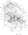
以下、本発明の一実施形態を、図面を参照して説明する。本実施形態では、ワークをプレス加工するプレスシステムを例にとって説明する。図1は、本発明の一実施形態にかかるシステム(プレスシステム)の全体構成(概略)を斜視図により示している。図2は、図1のプレスシステムからプレスアセンブリを取り外した状態(概略)を斜視図により示している。 Hereinafter, an embodiment of the present invention will be described with reference to the drawings. In the present embodiment, a press system that presses a workpiece will be described as an example. FIG. 1 is a perspective view showing an overall configuration (schematic) of a system (press system) according to an embodiment of the present invention. FIG. 2 is a perspective view showing a state (outline) in which the press assembly is removed from the press system of FIG.
このプレスシステム1は、プレス装置10と、このプレス装置10に設置可能(セット可能)なプレスアセンブリ30とを備えている。プレス装置10は、例えば上下方向(Z方向、第1の方向)に互いに対向するベース11およびスライド部材12と、スライド部材12がベース11に対して上下方向に移動するようにスライド部材12を支持するフレーム13と、スライド部材12をベース11に対して上下方向に駆動させる駆動装置60とを備えている。すなわち、図2は、プレスアセンブリ30が搭載されていない状態のプレス装置10を示している。
The
また、このプレスシステム1は、補助システム110を備えている。図1および図2において、プレス装置10の前方(X方向プラス側)に破線で示されている部分が、プレスアセンブリ30により成形するワーク(ワークピース)100などをハンドリングするための補助システム110である。この補助システム110は、プレスアセンブリ30に含まれる複数の下型35a〜35dを支持プレート33a〜33eに対して前方にスライドさせる下型移動装置120と、スライドさせた下型35a〜35dに対してワーク100を供給および排出するためのワーク搬送装置130とを有している(図6ないし図8参照)。
Further, the
ベース(ステージ、ベース部、ベース部材、盤板、ボルスタ)11は、上面11aがほぼ長方形状となっている。スライド部材12もまた、上面12aがほぼ長方形状であって、ベース11の上方(Z方向プラス側)に位置するように、フレーム13にスライド可能に支持されている。スライド部材12は、ベース11に対して上下方向(Z方向)に移動する。フレーム13は、ベース11の四隅から上方に延びる(上下方向に延びる)4本の支柱13aを備えている。スライド部材12の四隅には、それぞれ、これらの支柱13aが通過する孔12bが設けられており、スライド部材12は、支柱13aにガイドされた状態で上下方向(Z方向)に動く。
The base (stage, base portion, base member, panel board, bolster) 11 has an
駆動装置60は、駆動流体、例えば、オイル(作動油)によりスライド部材12を上下方向(Z方向)に駆動させて、ワーク100に加工用の力を加えるものである。駆動装置60は、加圧装置61およびタンク(オイルタンク)62を含むオイル供給装置(油供給装置、油圧ユニット、オイルユニット)63と、加圧装置61により供給される駆動流体の流れを制御可能な流体回路70と、流体回路70(流体回路70に含まれるバルブ150〜152など)の制御を含む制御を行う制御ユニット140と、駆動流体により駆動される1つのメイン駆動シリンダ(メイン油圧シリンダ)81と、駆動流体により駆動される2つのサブ駆動シリンダ(サブ油圧シリンダ)82および83とを備えている(図9ないし図12参照)。これらの駆動シリンダ81〜83により、スライド部材12が上下方向に動かされる。典型的な加圧装置61は、作動オイルを加圧して送り出すポンプである。
The driving
プレスアセンブリ30は、ベース11とスライド部材12の間に配置され、スライド部材12により圧力が加えられる。プレスアセンブリ30に配置された金型31a〜31dにより、ワーク(ワークピース)100が加工される。ベース11の上面11aには、プレスアセンブリ30を後方(X方向マイナス側)に移動させるために、前後方向(X方向)に延びた複数のローラ11rが設けられている。これらのローラ11rは、エアー浮上式のローラ(ローラーユニット)であり、例えば、フリーベア社のエアー浮上式ローラーユニットを用いることができる。これらのローラ11rは、浮上用のエアーを供給することにより、ローラ11rの表面(接触面)11cがベース11の表面(上面)11aの上に突き出る。
The
これらのローラ11rによりプレスアセンブリ30を前方および後方(X方向、前後方向)に移動させることができる。浮上用のエアーを抜くことにより、ローラ11rの接触面11cがベース11の表面11aよりも下がり、プレスアセンブリ30はベース11の表面11aに乗る。したがって、スライド部材12により加えられる圧力をベース11により受けることができる。さらに、ベース11の表面11aには、安全のために、プレスアセンブリ30が表面11aの上を不用意に移動することを禁止するためのロック機構11dが設けられている。
These
このプレスシステム1は、さらに、ベース11の後方(X方向マイナス側)に配置された第1の後方ベース21を備えている。第1の後方ベース21には、プレスアセンブリ30の移動方向を変換可能な複数の第1のローラ21rが配置されている。これらの第1のローラ21rとしては、例えば、フリーベア社のボールローラユニットを用いることができる。それぞれの第1のローラ21rは、プレスアセンブリ30を支持するメインボールと、メインボールを支持する多数の小ボールとを備えている。第1のローラ21rにおいては、メインボールの回転方向が自由なので、プレスアセンブリ30の移動方向を自由に変えることができる。複数の第1のローラ21rは、それぞれ、それらの接触面21cが、突出したときの複数のローラ11rの接触面11cとほぼ同じ高さになるように、第1の後方ベース21に設置(配置)されている。したがって、プレスアセンブリ30をベース11から第1の後方ベース21にスムーズに移動させることができる。
The
このプレスシステム1は、さらに、第1の後方ベース21に隣接する第2の後方ベース22を備えている。本例では、第2の後方ベース22は、ベース側(前側)から見て、第1の後方ベース21の右側(Y方向プラス側)に配置されている。第2の後方ベース22には、第1の後方ベース21との間でプレスアセンブリ30を移動可能な複数の第2のローラ22rが設けられている。これらの第2のローラ22rは、第1の後方ベース21との間でプレスアセンブリ30がY方向(左右方向)に移動可能となるように、Y方向に延びている。複数の第2のローラ22rは、それぞれ、それらの接触面22cが、第1のローラ21rの接触面21cとほぼ同じ高さになるように、第2の後方ベース22に設置(配置)されている。
The
このプレスシステム1は、さらに、第1の後方ベース21に隣接する第3の後方ベース23を備えている。本例では、第3の後方ベース23は、ベース側(前側)から見て、第1の後方ベース21の左側(Y方向マイナス側)に配置されている。第3の後方ベース23には、第1の後方ベース21との間でプレスアセンブリ30を移動可能な複数の第3のローラ23rが設けられている。これらの第3のローラ23rは、第1の後方ベース21との間でプレスアセンブリ30がY方向(左右方向)に移動可能となるように、Y方向に延びている。複数の第3のローラ23rは、それぞれ、それらの接触面23cが、第1のローラ21rの接触面21cとほぼ同じ高さになるように、第3の後方ベース23に設置(配置)されている。
The
このプレスシステム1は、さらに、スライド部材12よりも上方に位置するように、フレーム13に固定された第1のルーフ15を備えている。第1のルーフ15は、フレーム13が備える4本の支柱13aに支持されている。1つのメイン駆動シリンダ81、2つのサブ駆動シリンダ82および83、流体回路70は、それぞれ、第1のルーフ15の上に設けられている。
The
また、このプレスシステム1は、さらに、第1ないし第3の後方ベース21〜23の上方であって、第1のルーフ15と同程度の高さに固定された第2のルーフ16を備えている。本例では、第2のルーフ16は、第1のルーフ15よりも若干低いが、ほぼ同じ高さに配置されている。第2のルーフ16は、第1ないし第3の後方ベース21〜23の周囲に配置された複数の支柱17に支持されている。加圧装置61を含む油供給装置63は、第2のルーフ16の上に設けられている。さらに、このプレスシステム1では、第3の後方ベース23の上方に位置するように、プレスアセンブリ30に金型を取り付けたり、メンテナンスするためのリフト18が搭載されている。
The
油供給装置63と流体回路70とは、油を油供給装置63から流体回路70に供給するサプライライン91と、油を流体回路70から油供給装置63に戻すリターンライン92とにより接続されている。
The
メイン駆動シリンダ81と流体回路70とは、メイン駆動シリンダ81用のライン(配管)93aおよび93bにより接続されている。ライン93aは、メイン駆動シリンダ81のシャフト81sとは反対側の領域81Aと流体回路70とを接続しており、ライン93bは、メイン駆動シリンダ81のシャフト81s側の領域81Bと流体回路70とを接続している(図9ないし図12参照)。
The
サブ駆動シリンダ82と流体回路70とは、サブ駆動シリンダ82用のライン(配管)94aおよび94bにより接続されている。ライン94aは、サブ駆動シリンダ82のシャフト82sとは反対側の領域(下降用シリンダ室)82aと流体回路70とを接続しており、ライン94bは、サブ駆動シリンダ82のシャフト82s側の領域(上昇用シリンダ室)82bと流体回路70とを接続している(図9ないし図12参照)。
The
同様に、サブ駆動シリンダ83と流体回路70とは、サブ駆動シリンダ83用のライン(配管)95aおよび95bにより接続されている。ライン95aは、サブ駆動シリンダ83のシャフト83sとは反対側の領域(下降用シリンダ室)83aと流体回路70とを接続しており、ライン95bは、サブ駆動シリンダ83のシャフト83s側の領域(上昇用シリンダ室)83bと流体回路70とを接続している(図9ないし図12参照)。
Similarly, the
図3は、プレスアセンブリがベースに搭載された状態を上方から透かして見た図である。図3においては、ベース11に、これから使用する(または現在使用している)プレスアセンブリ30が搭載されているとともに、第2の後方ベースに、次に使用するプレスアセンブリ30Sが搭載された状態を示している。
FIG. 3 is a view of the state where the press assembly is mounted on the base as seen through from above. In FIG. 3, the
ベース11と第1の後方ベース21との間には、第1の後方ベース21を上下に貫通する開口24が設けられている。プレスアセンブリ30において発生する切り屑などは、この開口24を介して、第1の後方ベースの下方に排出される。また、プレスアセンブリ30がベース11と第1の後方ベース21との間を移動している最中に、プレスアセンブリ30の姿勢が不安定になることを防止するために、第1の後方ベースの開口24の左右(Y方向)両側には、X方向に延びる補助ローラ25が配置されている。これらの補助ローラ25の接触面25cは、第1のローラ21rの接触面21cとほぼ同じ高さになるように調整されている。
Between the
第1の後方ベース21の後方(X方向マイナス側)には、第1の後方ベース21を介して、プレスシステム1(プレス装置10)にプレスアセンブリ30を搬入および搬出するために、U字型に若干凹んだベイ26が設けられている。プレスシステム1(プレス装置10)にプレスアセンブリを搬入または搬出する場合には、運搬車(不図示)に載せたプレスアセンブリ30をベイ26に寄せ、第1の後方ベース21を介して、搬入または搬出する。プレスアセンブリ30がベイ26の近傍を移動している最中に、プレスアセンブリ30の姿勢が不安定になることを防止するために、第1の後方ベース21のベイ26の左右(Y方向)両側には、X方向に延びる補助ローラ27が配置されている。これらの補助ローラ27の接触面27cは、第1のローラ21rの接触面21cとほぼ同じ高さになるように調整されている。
At the rear of the first rear base 21 (minus in the X direction), a U-shape is formed to carry the
このプレスシステムは、ベース11や第1のルーフ15を支持する4本の脚28を備えている。また、このプレスシステム1は、第1の後方ベースないし第3の後方ベース21〜23や第2のルーフ16を支持する6本の脚29を備えている。このプレスシステムは、これらの脚28および29を介して工場などの床面に設置される。また、これらの脚28および29の高さは、微調整が可能である。これらの脚28および29の高さを微調整することにより、ベース11の上面11aおよびローラ11rの接触面11c、第1の後方ベース21およびローラ21rの接触面21c、第2の後方ベース22およびローラ22rの接触面22c、第3の後方ベース23およびローラ23rの接触面23cなどの高さを微調整することができる。
The press system includes four
このプレスシステム1では、ベース11上(ベース11とスライド部材12との間)に設置されているプレスアセンブリ30を、第1の後方ベース21を介して、第2の後方ベース22または第3の後方ベース23のいずれか一方(本例では、第3の後方ベース23)へ移動させることができる。また、第2の後方ベース22または第3の後方ベース23の他方(本例では、第2の後方ベース22)に予め他のプレスアセンブリ30Sを用意しておくことにより、このプレスアセンブリ30Sを、第1の後方ベース21を介して、ベース11上に設置することができる。したがって、プレスアセンブリにおける金型交換を、第2の後方ベース22の位置や第3の後方ベース23の位置で行うことができる。本例では、プレスアセンブリ30における金型交換を、第3の後方ベース23の位置で行うことができる。また、その間(金型交換の間)も、ベース11の位置において、プレス加工を行うことができる。このため、金型交換に要する手間および時間を短縮できる。
In the
このシステムによれば、ベース11と上下方向(Z方向)に動くスライド部材12との間にプレスアセンブリ30がセットされているため、スライド部材12を上下方向に移動させることにより、ワーク100に圧力を加え、ワーク100を加工することができる。第2の後方ベース22に配置されたプレスアセンブリ30Sは、例えば、異なるワークを加工するためのアセンブリである。プレスアセンブリ30により、所定の数のワーク100の加工が終了すると、ベース11にセットされていたプレスアセンブリ30を、図3に矢印S1で示すように、第1の後方ベース21を介して、第3の後方ベース23に移動させる。
According to this system, since the
その後、第2の後方ベース22に予めセットされていたプレスアセンブリ30Sを、図3に矢印S2で示すように、第1の後方ベース21を介して、ベース11にセットし、同様にして、次の異なるワークの加工を開始する。この間に、第3の後方ベース23の位置において、プレスアセンブリ30における金型交換を行うことができる。あるいは、第1の後方ベース21を介してプレスアセンブリ30を搬出し、第1の後方ベース21を介して第2の後方ベース22または第3の後方ベース23に、新しいプレスアセンブリを搬入してもよい。
Thereafter, the
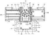
図4は、ベース11に(ベース11とスライド部材12との間に)プレスアセンブリ30がセットされた状態を抜き出して前方から見た図である。図4においては、第1ないし第3の後方ベース21〜23およびそれらに関する構造は省略している。図4では、ローラ11rがベース11に沈んだ状態(ローラ11rの接触面11cがベース11の上面11aに対して凹んだ状態)になっている。
FIG. 4 is a view of a state in which the
このプレスシステム1に設置されるプレスアセンブリ30は、例えば、4層構造である。プレスアセンブリ30は、3層以下または5層以上の構成であってもよいが、以下では4層構造を例に説明する。このプレスアセンブリ30は、4層の金型設置スペース32a〜32dを形成するように積層配置された5つの支持プレート33a〜33eと、最下層の支持プレート33aに対して上方の支持プレート33b〜33eを上下にスライドするように支持するアセンブリフレーム34とを有する。アセンブリフレーム34は、支持プレート33a〜33eの四隅を支持するシャフト34aを備えている。最下層の支持プレート33aを除き、他の支持プレート33b〜33eは、四隅にシャフト34aが通る孔を備えており、シャフト34aに沿って上下に動く。
The
最上層の支持プレート33eを除き、それぞれの支持プレート(最下層の支持プレートおよび中間の支持プレート)33a〜33dの表面(上面)には、下型35a〜35dが設置されている。また、最下層の支持プレート33aを除き、それぞれの支持プレート(最上層の支持プレートおよび中間の支持プレート)33b〜33eの裏面(下面)には、上型36a〜36dが設置されている。したがって、4層の金型設置スペース32a〜32dのそれぞれには、下型35a〜35dと上型36a〜36dとを備えた金型31a〜31dが配置されている。プレスアセンブリ30の最下層の支持プレート33aは、着脱式のロック機構11dにより、ベース11に固定される。プレスアセンブリ30の最上層の支持プレート33eは、スライド部材12に、着脱式の取付機構(不図示)により取り付けられる。取付機構としては、例えば、支持プレート33eの両側を挟んで止めるフックを用いることができる。
Except for the
駆動シリンダ(油圧シリンダ、オイルシリンダ)82および83により、スライド部材12を下方に移動(下降)させると、支持プレート33b〜33eは下がり、金型31a〜31dの上型36a〜36dと下型35a〜35dとが重なる。
When the
スライド部材12に対し、駆動シリンダ(油圧シリンダ、オイルシリンダ)81〜83により上方から圧力が加わると、プレスアセンブリ30においては、最上層の支持プレート33eに、スライド部材12を介して、圧力が伝達される。プレスアセンブリ30においては、さらに、積層配置された金型31a〜31dを介して、圧力が下層の支持プレート33a〜33dに順次伝達される。最下層の支持プレート33aは、ベース11により支持されているため、この結果、プレスアセンブリ30は、ベース11とスライド部材12とにより挟み込まれて加圧された(プレスされた)状態となる。
When pressure is applied to the
すなわち、金型設置スペース32a〜32dにおいては、それぞれの下側の支持プレート33a〜33dと、それぞれの上側の支持プレート33b〜33eとの間に圧力が加わり、それらにはさまれたそれぞれの金型31a〜31dに、ワーク100を加工するための圧力が加わる。したがって、金型31a〜31dのそれぞれにおいて、下型35a〜35dのそれぞれと、上型36a〜36dのそれぞれとによりそれぞれ挟み込まれたワーク100は、プレス加工される。
That is, in the
一方、駆動シリンダ(油圧シリンダ、オイルシリンダ)82および83により、スライド部材12を上方に移動(上昇)させると、最上層の支持プレート33eは、スライド部材12とともに上方へ移動する。最上層の支持プレート33eが上方へ動くと、最下層の支持プレート33aを除く支持プレート33b〜33dは、それぞれの支持プレート33a〜33eの間が開くように上方へ移動する。このような機構は、支持プレート33a〜33eのそれぞれの間に、コイルばねなどの弾性体を入れることにより実現することが可能である。また、支持プレート33b〜33eが、プレート同士の間隔が所定の値になると上方に引っ張られるような機構を採用してもよい。
On the other hand, when the
また、上述のように、補助システム110は、プレス装置10の前面(前方)に、下側の支持プレート33a〜33dから下型35a〜35dをそれぞれ前方に引き出す下型移動装置120を備えている(図6ないし図8参照)。この下型移動装置120は、上下に延びたシャフト121と、シャフト121を駆動するためのモータ122と、シャフト121により伝達される駆動力により、下型35a〜35dを前方に引き出す引出装置123とを備えている。この補助システム110では、スライド部材12を最上部に停止させた状態において、下型移動装置120により、下型35a〜35dをそれぞれ前方に引き出し、ワーク100を出し入れする。
Further, as described above, the
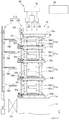
図5は、このプレスシステム1を用いたプレス方法の一例を説明するためのフローチャートである。図6ないし図8は、ベース11とスライド部材12との間にセットされたプレスアセンブリ30および補助システム110(下型移動装置120、ワーク搬送装置130)を抜き出して側方から見た図である。図6は、プレスアセンブリ30の金型31a〜31dによりワーク100のプレスが行われている状態(プレスアセンブリ30の金型31a〜31dに圧力が加わった状態)を示している。図7は、スライド部材12を上方に停止させて、プレスアセンブリ30の金型31a〜31d(下型35a〜35d)からワーク100を搬送している状態(プレスアセンブリ30の金型31a〜31dからワーク100を搬出している状態)を示している。図8は、スライド部材12を上方に停止させて、ワーク搬送装置130によりワーク100を上方に搬送している状態を示している。
FIG. 5 is a flowchart for explaining an example of a press method using the
まず、ステップ201において、2つのサブ駆動シリンダ82および83により、スライド部材12を下降させる。ステップ202において、1つのメイン駆動シリンダ81および2つのサブ駆動シリンダ82および83により、スライド部材12を介して圧力を加える。これにより、図6に示すように、それぞれの金型31a〜31dにおいて、ワーク100のプレスが行われる。ステップ203において、2つのサブ駆動シリンダ82および83により、スライド部材12を上昇させる。
First, in
ステップ204において、スライド部材12を最上部に停止させる。図7に示すように、この停止状態において、下型移動装置120により、下型35a〜35dをそれぞれ前方に引き出し、下型35a〜35dからワーク100を取り出す。その後、図8に示すように、この停止状態において、ワーク搬送装置130により、ワーク100を一段上の下型35b〜35dに移動させる。最も下側の金型31aの下型35aには、コンベア101から新しいワーク100が供給され、最も上側の金型31dにおいてプレス加工が終了したワーク100は、異なるワーク搬送装置(図示せず)により、プレスシステム1の外に搬出される。すなわち、このプレスシステム1では、ワーク100は、最も下側の金型31aから最も上側の金型31dに順番に搬送され、それぞれの金型31a〜31dにおいて、異なる4つのプレス加工が連続して行われる。プレスを要するワーク100が無くなると、ステップ205において、ジョブを終了する。
In
このように、このプレスシステム1は、ロボット搬送方式により、順送りにワーク100を複数の金型31a〜31dに送って多段階のプレス加工を行うことができる。さらに、複数の金型31a〜31dは、1つのプレスアセンブリ30として組み立てられており、プレスアセンブリ30を交換するだけで、多種多様なプレス加工を行うことができる。プレスアセンブリ30は、最下層の支持プレート33aの上に複数の金型31a〜31dが積層された構造となっている。このため、最下層の支持プレート33aをプレス装置10のベース11に対して動かせば、ベース11およびスライド部材12の間からプレスアセンブリ30を外すことができ、複数の金型31a〜31dをプレスアセンブリ30毎に交換できる。したがって、盤板として機能するベース11、スライド部材12、駆動装置60といったプレスシステム1の主要な構成を交換したり、分解したりせずに、上型および下型を含めた複数の金型31a〜31dを簡単に、短時間で交換することが可能である。
As described above, the
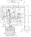
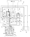
次に、このプレスシステム1が備える駆動装置(油圧系)60について説明する。図9ないし図12は、それぞれ、このプレスシステム1が備える駆動装置60を示している。図9は、スライド部材12を下降させている状態のオイルの流れを説明するための図である。図10は、プレスアセンブリ30の金型31a〜31dによりワーク100のプレスが行われている状態のオイルの流れを説明するための図である。図11は、スライド部材12を上昇させている状態のオイルの流れを説明するための図である。図12は、スライド部材12を停止させている状態を示す図である。
Next, the drive device (hydraulic system) 60 provided in the
上述のように、駆動装置60は、加圧装置61およびオイルタンク62を含むオイル供給装置63と、加圧装置61により供給される駆動流体の流れを制御可能な流体回路70と、駆動流体により駆動される1つのメイン駆動シリンダ81と、駆動流体により駆動される2つのサブ駆動シリンダ82および83と、流体回路70の制御を含む制御を行う制御ユニット140とを含んでいる。なお、図中、符号181は油圧計であり、符号182はゲージダンパである。
As described above, the
2つのサブ駆動シリンダ82および83は、互いに同形状であり、メイン駆動シリンダ81の内径(断面積)は、サブ駆動シリンダ82および83の内径(断面積)よりも大きい。また、本例では、メイン駆動シリンダ81の内径(ピストン径)、サブ駆動シリンダ82および83の内径(ピストン径)およびシャフト(ピストンシャフト)82sおよび83sの径は、シリンダ81の断面積(ピストンの表面積)(以下のWAに相当)に対して、サブ駆動シリンダ82および83の断面積(ピストンの表面積)からシャフト82sおよび83sの断面積を引いた値(以下のWbに相当)が大きくなるように設定されている。したがって、2つのサブ駆動シリンダ82および83のシャフト側の領域(上昇用シリンダ室、以降ではb側)82bおよび83bの容積(容量)の総変化量Wbが、メイン駆動シリンダ81のシャフトとは反対側の領域(下降用シリンダ室、以降ではA側)81Aの容積(容量)の総変化量WAよりも大きくなるように設定されている。すなわち、以下の(1−2)式を満たす。
WA < 2Wb・・・(1−2)
The two
WA <2Wb (1-2)
流体回路70は、メインバルブ(弁)150と、第1のバルブ(弁)151と、第2のバルブ(弁)152と、パイロットチェックバルブ(弁)154と、カウンタバランスバルブ(弁)155と、アングルチェックバルブ(弁)156と、これらのバルブ150〜152,154〜156、各シリンダ81〜83およびオイルユニット63とを接続する配管ブロック153とを含む。
The
配管ブロック153は、ポート153aおよび153bに接続されたサプライライン91およびリターンライン92を介して、オイル供給装置63と連通している。また、配管ブロック153は、ポート153cおよび153dに接続されたメイン駆動シリンダ81用のライン(配管)93aおよび93bを介して、メイン駆動シリンダ81と連通している。ライン93aは、メイン駆動シリンダ81の下降用シリンダ室(A側またはA室)81Aに通じるポートに接続されている。ライン93bは、メイン駆動シリンダ81の反対側のシリンダ室(以降ではB側またはB室)81Bに通じるポートに接続されている。
The
さらに、配管ブロック153は、ポート153eおよび153fに接続されたサブ駆動シリンダ82用のライン(配管)94aおよび94bを介して、サブ駆動シリンダ82と連通している。ライン94aは、サブ駆動シリンダ82の下降用シリンダ室(以降ではa側またはa室)82aに通じるポートに接続されている。ライン94bは、サブ駆動シリンダ82の上昇用シリンダ室(以降ではb側またはb室)82bに通じるポートに接続されている。
Further, the
同様に、配管ブロック153は、ポート153eおよび153fに接続されたサブ駆動シリンダ83用のライン(配管)95aおよび95bを介して、サブ駆動シリンダ83と連通している。ライン95aは、サブ駆動シリンダ83の下降用シリンダ室(以降ではa側またはa室)83aに通じるポートに接続されている。ライン95bは、サブ駆動シリンダ83の上昇用シリンダ室(以降ではb側またはb室)83bに通じるポートに接続されている。
Similarly, the
配管ブロック153は、ポート153gおよび153hに接続された第1の経路161により第1のバルブ(弁)151に接続されている。第1のバルブ(弁)151は、制御ユニット140により開閉されるバルブであって、例えば、電磁ストップバルブ(弁)である。したがって、第1のバルブ151により第1の経路161が開閉される(図9参照)。ポート153gは、ポート153f(サブシリンダ82および83のb側82bおよび83b)に繋がり、ポート153hは、ポート153c(メイン駆動シリンダ81のA側81A)と接続されている。したがって、第1のバルブ151により、サブシリンダ82および83のb側82bおよび83bと、メイン駆動シリンダ81のA側81Aと連通させる第1の経路161を開閉できる。
The
第2のバルブ(弁)152は、例えば、電磁油圧切換バルブ(弁)であって、第1のポジションと第2のポジションとを有しており、制御ユニット140によりこれらのポジションが制御される。第2のバルブ152は、配管ブロック153のポート153i、153jおよび153kと接続されており、第1のポジションでは、ポート153iおよび153jを連通し、ポート153kをストップ(閉に)する。第2のポジションでは、ポート153kおよび153iを連通し、ポート153jをストップする。ポート153iは、ポート153c(メイン駆動シリンダ81のA側81A)と接続されている。ポート153jは、ポート153d(メイン駆動シリンダ81のB側81B)およびポート153b(リターン配管92、ただし、チェックバルブ156を介して)に接続されている。ポート153kは、ポート153e(サブ駆動シリンダのa側82aおよび83a)に接続されている。したがって、第2のバルブ152を第1のポジションとすると、メイン駆動シリンダ81のA側81AとB側81Bとが連通し、さらに、チェックバルブ156を介してメイン駆動シリンダ81のA側81AとB側81Bとをリターン配管92に連通できる。また、第2のバルブ152を第2のポジションとすることにより、メイン駆動シリンダ81のA側81Aに対し、サブ駆動シリンダ82および83のa側82aおよび83aと同様に、オイル供給装置63からオイルを供給できる(経路171、図10参照)。
The second valve (valve) 152 is, for example, an electromagnetic hydraulic switching valve (valve), and has a first position and a second position, and these positions are controlled by the
メインバルブ(弁)150は、例えば、電磁油圧切換バルブ(弁)であって、第1ないし第3のポジションを有しており、制御ユニット140によりこれらのポジションが制御される。メインバルブ150は、配管ブロック153のポート153m、153n、153pおよび153qと接続されている。メインバルブ150を第1のポジションとすることにより、ポート153nとポート153pとが接続され、ポート153pは153a(オイルサプラインライン91)に繋がる。また、ポート153nは、ポート153e(サブ駆動シリンダ82および83のa側82aおよび83a)に繋がる。したがって、オイル供給装置63からサブ駆動シリンダ82および83のa側82aおよび83aへオイルが供給され、スライド部材12が下降する。また、メインバルブ150を第1のポジションとすることにより、パイロットチェックバルブ(弁)154およびカウンタバランスバルブ(弁)155とを介して、ポート153mとポート153qとが接続され、ポート153qは、ポート153b(オイルリターンライン92)に繋がる。また、ポート153mは、ポート153f(サブ駆動シリンダ82および83のb側82bおよび83b)に繋がる。したがって、条件により、サブ駆動シリンダ82および83のb側82bおよび83bからオイルをオイルユニット63へ逃がすことができる。
The main valve (valve) 150 is, for example, an electrohydraulic switching valve (valve) and has first to third positions, and these positions are controlled by the
メインバルブ150を第2のポジションとすることにより、ポート153m〜153pのすべてをストップする。したがって、いずれのシリンダ81〜83にもオイルが供給されなくなり、スライド部材12を停止できる。
By setting the
メインバルブ150を第3のポジションとすることにより、ポート153mとポート153pとを接続でき、ポート153nとポート153qとを接続できる。したがって、ポート153pからポート153mを介してポート153f(サブ駆動シリンダ82および83のb側82bおよび83b)にオイルを供給でき、ポート153e(サブ駆動シリンダ82および83のa側82aおよび83a)からポート153nを介してポート153qへオイルを逃がすことができる。したがって、メインバルブ150を第3のポジションとすることにより、サブ駆動シリンダ82および83によりスライド部材12は上昇する。
By setting the
図9は、スライド部材12を下降させている状態のオイルの流れを示している。太線がオイルのサプライ経路(供給側の経路)を示し、破線がオイルのリターン経路(戻り側の経路)を示している。以下の図においても同様である。図9では、メインバルブ150を第1のポジション、第1のバルブ151を第2のポジション(開ポジション)、第2のバルブ152を第1のポジションにセットしている(図13参照)。メインバルブ150を第1のポジションとすることにより、太線で示すように、サブ駆動シリンダ82および83のa側(下降用シリンダ室)82aおよび83aにオイル供給装置63からオイルが供給され、スライド部材12は、サブ駆動シリンダ82および83のみで下降する。したがって、メイン駆動シリンダ81を使用する場合よりも高速で、スライド部材12を下降させることができる。
FIG. 9 shows an oil flow in a state where the
第1のバルブ151を第2のポジション(開ポジション)とすることにより、第1の経路161が開かれ、一点鎖線で示すように、サブ駆動シリンダ82および83のb側(上昇用シリンダ室)82bおよび83bから排出されるオイルは、メイン駆動シリンダ81のA側(下降用シリンダ室)81Aに供給される。メイン駆動シリンダ81のB側81Bから排出されたオイルは、ポート153dからポート153bを介してオイルユニット63に戻される。したがって、メイン駆動シリンダ81の下降用シリンダ室81Aには、十分なオイルがサブ駆動シリンダ82および83から供給され、メイン駆動シリンダ81が抵抗となるのを防止できる。
By setting the
本例では、上記(1−2)式を満たすように、駆動シリンダ81〜83が設計されているため、サブ駆動シリンダ82および83の上昇用シリンダ室82bおよび83bから吐出されるオイルは、メイン駆動シリンダ81の下降用シリンダ室81Aに供給しても余る。第2のバルブ152が第1のポジションになっているので、サブ駆動シリンダ82および83のb側(上昇用シリンダ室)82bおよび83bから排出されるオイルのうち、余ったオイルは、第2のバルブ152およびリターンライン92を介してオイル供給装置63に戻る。
In this example, since the
図10は、プレスが行われている状態のオイルの流れを示している。プレスの際には、メインバルブ150を第1のポジション、第1のバルブ151を第1のポジション(閉ポジション)、第2のバルブ152を第2のポジションに設定する(図13参照)。第2のバルブ152を第2のポジションとして経路171を開くことにより、サブ駆動シリンダ82および83のa側(下降用シリンダ室)82aおよび82bに加え、メイン駆動シリンダ81のA側(下降用シリンダ室)81Aに、オイル供給装置63からオイルが供給される。これにより、スライド部材12は、ワーク100のプレスに必要な程度の大きな力で下側に押される。これにより、ワーク100はプレスされる。
FIG. 10 shows an oil flow in a state where pressing is performed. At the time of pressing, the
メイン駆動シリンダ81のB側81Bから排出されたオイルは、図9と同様のルートでオイルユニット63に戻る。サブ駆動シリンダ82および83のb側82bおよび83bから排出されたオイルは、第1のバルブ151が閉になり、ポート153nに加わる油圧によりパイロットチェックバルブ(弁)154およびカウンタバランスバルブ(弁)155のルートが開になるので、メインバルブ150を介してオイルユニット63へ戻る。
The oil discharged from the
図11は、スライド部材12を上昇させている状態のオイルの流れを示している。メインバルブ150を第3のポジション、第1のバルブ151を第1のポジション(閉ポジション)、第2のバルブ152を第1のポジションに設定する(図13参照)。メインバルブ150を第3のポジションとすることにより、サブ駆動シリンダ82および83のb側(上昇用シリンダ室)82bおよび83bにオイル供給装置63からオイルが供給され、スライド部材12は上昇する。サブ駆動シリンダ82および83のa側(下降用シリンダ室)82aおよび83aのオイルは、破線で示すように、メインバルブ150を介してオイル供給装置63に戻る。また、一点鎖線で示すように、メイン駆動シリンダ81のA側81Aから排出されたオイルは、第2のバルブ152を介して経路(循環経路)172を通り、メイン駆動シリンダ81のB側81Bに入り、余ったオイルは、破線で示すように、オイル供給装置63に戻る。
FIG. 11 shows the flow of oil in a state where the
図12は、スライド部材12を停止させている状態を示している。スライド部材12を停止する際には、メインバルブ150を第2のポジション、第1のバルブ151を第1のポジション(閉ポジション)、第2のバルブ152を第1のポジションに設定する(図13参照)。メインバルブ150を第2のポジションとすることにより、オイル供給装置63からのオイルの供給が停止され、スライド部材12は、停止する。
FIG. 12 shows a state in which the
図13は、上述した各バルブ150〜152の状態をまとめて示している。また、図13は、図1のプレスシステムの制御方法の一例を説明するためのフローチャートである。ステップ211において、スライド部材12を下降させる場合には、ステップ212において、メインバルブ150を第1のポジション、第1のバルブ151を第2のポジション、第2のバルブ152を第1のポジションとする。このようにすることにより、スライド部材12は、サブ駆動シリンダ82および83のみで下降する。したがって、メイン駆動シリンダ81を使用する場合よりも高速で、スライド部材12を下降させることができる。また、第1のバルブ151は第2のポジションであるため、第1の経路161が開いた状態となる。したがって、サブ駆動シリンダ82および83のシャフトとは反対側の領域82aおよび83aには、加圧装置61から駆動流体が供給され、メイン駆動シリンダ81のシャフトとは反対側の領域81Aには、サブ駆動シリンダ82および83のシャフト側の領域82bおよび83bから、第1の経路161を介して十分な量の駆動流体が供給される。このため、メイン駆動シリンダ81はほとんど抵抗にならない。
FIG. 13 collectively shows the states of the
プレス位置までスライド部材12を下降させ、ステップ213において、プレスする場合には、ステップ214において、メインバルブ150を第1のポジション、第1のバルブ151を第1のポジション、第2のバルブ152を第2のポジションとする。このようにすることにより、サブ駆動シリンダ82および83だけでなく、メイン駆動シリンダ81によっても、スライド部材12に下向きに力が与えられる。これにより、金型31a〜31dにおいて、ワーク100がプレスされる。
When the
プレス後、ステップ215において、スライド部材を上昇させる場合には、ステップ216において、メインバルブ150を第3のポジション、第1のバルブ151を第1のポジション、第2のバルブ152を第1のポジションとする。このようにすることにより、スライド部材12は、サブ駆動シリンダ82および83によって上昇する。
When the slide member is raised in
スライド部材12が所定の位置まで上昇し、ステップ217において、スライド部材12を停止させる場合には、ステップ218において、メインバルブ150を第2のポジション、第1のバルブ151を第1のポジション、第2のバルブ152を第1のポジションとする。このようにすることにより、スライド部材12は停止する。
When the
以上のように、本例のプレスシステム1および制御方法によれば、サブ駆動シリンダ82および83のみで駆動する際に、第1の経路161を介して、サブ駆動シリンダ82および83のb側82bおよび83bから、メイン駆動シリンダ81のA側81Aに駆動流体が供給される。しかも、本例では、上記(1−2)式を満たすように設定され、サブ駆動シリンダ82および83のb側の容積の総変化量が、メイン駆動シリンダ81のA側の容積の総変化量より大きい。このため、サブ駆動シリンダ82および83のb側82bおよび83bから吐出(排出)されるオイル量は、メイン駆動シリンダ81のA側81Aに吸い込まれるオイル量よりも多い。したがって、サブ駆動シリンダ82および83のb側82bおよび83bから吐出(排出)されるオイルにより、メイン駆動シリンダ81のA側81Aのディスプレイスメントを補完でき、メイン駆動シリンダ81がほとんど抵抗にならない。このため、サブ駆動シリンダ82および83のみによりスライド部材12を高速で下降させることができる。
As described above, according to the
さらに、本例のプレスシステム1によれば、第1のルーフ15に、メイン駆動シリンダ81、サブ駆動シリンダ82および83、および流体回路70を設け、第1ないし第3の後方ベース21〜23の上方であって、第1のルーフ15と同程度の高さの第2のルーフ16に加圧装置61(オイル供給ユニット63)を設けている。したがって、システム1を小型化でき、工場内のスペースを、高さ方向に有効活用できる。また、第1のルーフ15と第2のルーフ16とは接近しており、また、ほぼ同じ高さである。したがって、流体回路70と加圧装置61(オイル供給ユニット63)とを近接させて、しかも、ほとんど同じ高さに設置できる。このため、流体回路70と加圧装置61(オイル供給ユニット63)との間における配管およびヘッド差による圧力損失を低減できる。
Further, according to the
図14は、図1のプレスシステムが備える駆動装置を示す図であって、スライド部材を下降させている状態のオイルの流れの変形例を説明するための図である。 FIG. 14 is a diagram illustrating a drive device provided in the press system of FIG. 1, and is a diagram for describing a modification example of the oil flow in a state where the slide member is lowered.
本例では、メイン駆動シリンダ81の内径(ピストン径)およびシャフト(ピストンシャフト)81sの径、サブ駆動シリンダ82および83の内径(ピストン径)およびシャフト(ピストンシャフト)82sおよび83sの径は、シリンダ81の断面積(ピストンの表面積)(WAに相当)に対して、サブ駆動シリンダ82および83の断面積(ピストンの表面積)からシャフト82sおよび83sの断面積を引いた値(Wbに相当)と、シリンダ81の断面積(ピストンの表面積)からシャフト81sの断面積を引いた値(WBに相当)との和が、大きくなるように設定されている。したがって、2つのサブ駆動シリンダ82および83のシャフト側の領域(上昇用シリンダ室、b側)82bおよび83bの容積(容量)の総変化量Wbと、メイン駆動シリンダ81のシャフト側の領域(B側)81Bの容積(容量)の総変化量WBとの和が、メイン駆動シリンダ81のシャフトとは反対側の領域(下降用シリンダ室、A側)81Aの容積(容量)の総変化量WAよりも大きくなるように設定されている。すなわち、以下の(2−2)式を満たすように、メイン駆動シリンダ81とサブ駆動シリンダ82および83との大きさ(内径(断面積))や形状が設定されている。
WA < 2Wb+WB・・・(2−2)
In this example, the inner diameter (piston diameter) of the
WA <2Wb + WB (2-2)
このため、第1のバルブ151で開(第2のポジション)になる第1の経路161を介して供給されるサブ駆動シリンダ82および83のb側82bおよび83bの排出オイルに加えて、第2のバルブ152により開(第1のポジション)になる第2の経路162を介して供給されるメイン駆動シリンダ81のB側81Bの排出オイルが、メイン駆動シリンダ81のA側81Aに供給される。メイン駆動シリンダ81のB側81Bから排出されるオイルのうち、余ったオイルは、ポート153bを通ってオイルユニット63へ戻される。
For this reason, in addition to the discharged oil on the
この例では、メイン駆動シリンダ81のB側81Bから排出されるオイルを、メイン駆動シリンダ81のA側81Aを補充(補填)するために使うことができる。このため、サブ駆動シリンダ82および83のピストン面積が上記の例よりも若干小さくてよく、サブ駆動シリンダ82および83の選択肢が広がり、サブ駆動シリンダ82および83による動作をさらに高速化できる可能性がある。
In this example, the oil discharged from the
なお、本発明のシステムは、プレスシステムに限定されるものではなく、第1の方向に互いに対向するベースおよびスライド部材において、ベースに対してスライド部材を駆動(スライド)させるようなシステム全般に適用できる。また、上記実施形態のシステムでは、第1ないし第3の後方ベースを備えているが、第1ないし第3の後方ベースを含まないプレスシステムに対しても、メインおよびサブ駆動シリンダを備えた駆動装置は適用できる。 Note that the system of the present invention is not limited to the press system, and is applicable to all systems in which the slide member is driven (slid) relative to the base in the base and the slide member facing each other in the first direction. it can. In the system of the above embodiment, the first to third rear bases are provided, but the drive system including the main and sub drive cylinders is also provided for a press system that does not include the first to third rear bases. The device is applicable.
さらに、上記実施形態のシステムでは、1つのメイン駆動シリンダと、2つのサブ駆動シリンダを備えているが、メイン駆動シリンダは2つ以上であってもよく、また、サブ駆動シリンダは3つ以上であってもよい。また、その場合、複数のメイン駆動シリンダが必ずしも同形状でなくともよく、また、複数のサブ駆動シリンダも、必ずしも同形状でなくてもよい。 Further, in the system of the above embodiment, one main drive cylinder and two sub drive cylinders are provided. However, the number of main drive cylinders may be two or more, and the number of sub drive cylinders is three or more. There may be. In this case, the plurality of main drive cylinders do not necessarily have the same shape, and the plurality of sub drive cylinders do not necessarily have the same shape.
1 プレスシステム、 11 ベース、 12 スライド部材
15 第1のルーフ、 16 第2のルーフ
21 第1の後方ベース、 22 第2の後方ベース、 23 第3の後方ベース
60 駆動装置、 61 加圧装置、 70 流体回路
81 メインシリンダ、 82、83 サブシリンダ
151 第1のバルブ、 152 第2のバルブ
161 第1の経路、 162 第2の経路
DESCRIPTION OF
Claims (5)
前記ベースに対して前記スライド部材を駆動する駆動装置とを有するシステムであって、
前記駆動装置は、タンク内の駆動流体を加圧供給する加圧装置と、前記加圧装置により供給される前記駆動流体の流れを制御可能な流体回路と、前記駆動流体により駆動される少なくとも1つのメイン駆動シリンダと、前記駆動流体により駆動される複数のサブ駆動シリンダとを備え、
前記流体回路は、前記複数のサブ駆動シリンダのシャフト側の領域と前記少なくとも1つのメイン駆動シリンダのシャフトとは反対側の領域とを連通させて前記複数のサブ駆動シリンダのシャフト側の領域の前記駆動流体を前記少なくとも1つのメイン駆動シリンダのシャフトとは反対側の領域に供給する第1の経路と、この第1の経路を開閉する第1のバルブと、前記第1の経路を介して供給される余剰の前記駆動流体をチェックバルブを介して前記タンクに戻す経路とを含み、前記複数のサブ駆動シリンダのシャフト側の領域の容積の総変化量は、前記少なくとも1つのメイン駆動シリンダのシャフトとは反対側の領域の容積の総変化量よりも大きい、システム。 A base and a slide member facing each other in a first direction;
A drive device for driving the slide member relative to the base,
The driving device includes a pressure device pressure supplying driving fluid in the tank, and a fluid circuit that can control the flow of the drive fluid supplied by said pressure device, at least one driven by said driving fluid Two main drive cylinders, and a plurality of sub drive cylinders driven by the drive fluid,
The fluid circuit communicates a region on the shaft side of the plurality of sub-drive cylinders with a region on the opposite side of the shaft of the at least one main drive cylinder, and the region in the shaft side of the plurality of sub-drive cylinders the driving fluid and shaft of the at least one main drive cylinder and the first path you supplied to the opposite side region has a first valve for opening and closing the first path, through the first path A path for returning the surplus drive fluid to be supplied to the tank via a check valve, and the total amount of change in the volume of the region on the shaft side of the plurality of sub drive cylinders is that of the at least one main drive cylinder A system that is larger than the total volume change in the area opposite the shaft .
前記ベースに対して前記スライド部材を駆動する駆動装置とを有するシステムであって、
前記駆動装置は、タンク内の駆動流体を加圧供給する加圧装置と、前記加圧装置により供給される前記駆動流体の流れを制御可能な流体回路と、前記駆動流体により駆動される少なくとも1つのメイン駆動シリンダと、前記駆動流体により駆動される複数のサブ駆動シリンダとを備え、
前記流体回路は、前記複数のサブ駆動シリンダのシャフト側の領域と前記少なくとも1つのメイン駆動シリンダのシャフトとは反対側の領域とを連通させて前記複数のサブ駆動シリンダのシャフト側の領域の前記駆動流体を前記少なくとも1つのメイン駆動シリンダのシャフトとは反対側の領域に供給する第1の経路と、この第1の経路を開閉する第1のバルブと、前記少なくとも1つのメイン駆動シリンダのシャフト側の領域と前記少なくとも1つのメイン駆動シリンダのシャフトとは反対側の領域とを連通させて前記少なくとも1つのメイン駆動シリンダのシャフト側の領域の前記駆動流体を前記少なくとも1つのメイン駆動シリンダのシャフトとは反対側の領域に供給する第2の経路と、この第2の経路を開閉する第2のバルブと、前記第1の経路および前記第2の経路を介して供給される余剰の前記駆動流体をチェックバルブを介して前記タンクに戻す経路とを含み、
前記複数のサブ駆動シリンダのシャフト側の領域の容積の総変化量と、前記少なくとも1つのメイン駆動シリンダのシャフト側の領域の容積の総変化量との和は、前記少なくとも1つのメイン駆動シリンダのシャフトとは反対側の領域の容積の総変化量よりも大きい、システム。 A base and a slide member facing each other in a first direction;
A drive device for driving the slide member relative to the base,
The driving device includes a pressurizing device that pressurizes and supplies the driving fluid in the tank, a fluid circuit capable of controlling a flow of the driving fluid supplied by the pressurizing device, and at least one driven by the driving fluid. Two main drive cylinders, and a plurality of sub drive cylinders driven by the drive fluid,
The fluid circuit communicates a region on the shaft side of the plurality of sub-drive cylinders with a region on the opposite side of the shaft of the at least one main drive cylinder, and the region in the shaft side of the plurality of sub-drive cylinders A first path for supplying drive fluid to a region opposite to the shaft of the at least one main drive cylinder; a first valve for opening and closing the first path; and a shaft of the at least one main drive cylinder A region on the side of the at least one main drive cylinder and a region on the opposite side of the shaft of the at least one main drive cylinder to communicate the drive fluid in the region on the shaft side of the at least one main drive cylinder with the shaft of the at least one main drive cylinder a second valve for opening and closing the second path you supplied to the opposite side region, the second path and, prior to The excess of the drive fluid supplied through the first path and the second path via a check valve and a path back to the tank,
The sum of the total amount of change in the volume on the shaft side of the plurality of sub drive cylinders and the total amount of change in the volume on the shaft side of the at least one main drive cylinder is the sum of the at least one main drive cylinder. A system that is larger than the total volume change in the area opposite the shaft.
前記スライド部材が前記ベースに対して前記第1の方向に移動するように、前記スライド部材を支持するフレームと、
前記ベースと前記スライド部材との間に設置されるプレスアセンブリと、
前記加圧装置とを有し、
前記ベースは、前記プレスアセンブリを後方に移動するためのローラであって、移動するときに前記ベースの表面に突出するローラを備え、
当該システムは、さらに、
前記ベースの後方に配置された第1の後方ベースであって、前記プレスアセンブリの移動方向を変換可能な第1のローラが、それらの接触面が前記ベースのローラの接触面とほぼ同じ高さになるように設置されている第1の後方ベースと、
前記第1の後方ベースに隣接する第2の後方ベースであって、前記第1の後方ベースとの間で前記プレスアセンブリを移動可能な第2のローラが、それらの接触面が前記第1のローラの接触面とほぼ同じ高さになるように設置されている第2の後方ベースと、
前記第1の後方ベースに対し、前記第2の後方ベースとは異なる方向で隣接する第3の後方ベースであって、前記第1の後方ベースとの間で前記プレスアセンブリを移動可能な第3のローラが、それらの接触面が前記第1のローラの接触面とほぼ同じ高さになるように設置されている第3の後方ベースと、
前記スライド部材よりも上方に位置するように、前記フレームに固定された第1のルーフと、
前記第1ないし第3の後方ベースの上方であって、前記第1のルーフと同程度の高さに固定された第2のルーフとを有し、
前記少なくとも1つのメイン駆動シリンダ、前記複数のサブ駆動シリンダ、および前記流体回路は、前記第1のルーフの上に設けられ、
前記加圧装置は、前記第2のルーフの上に設けられている、システム。 The system according to claim 1 or 2 , further comprising:
A frame that supports the slide member such that the slide member moves in the first direction relative to the base;
A press assembly installed between the base and the slide member;
The pressure device,
The base is a roller for moving the press assembly backward, and includes a roller that protrudes on a surface of the base when moving.
The system further includes
A first rear base disposed behind the base, the first roller capable of changing the direction of movement of the press assembly, the contact surface of which is substantially the same height as the contact surface of the roller of the base A first rear base installed to be,
A second rear base adjacent to the first rear base, the second roller being capable of moving the press assembly between the first rear base and a contact surface of the second roller; A second rear base installed so as to be substantially the same height as the contact surface of the roller;
A third rear base adjacent to the first rear base in a direction different from that of the second rear base, the third rear base being movable between the first rear base and the third rear base. A third rear base installed such that their contact surfaces are substantially level with the contact surface of the first roller;
A first roof fixed to the frame so as to be positioned above the slide member;
A second roof which is above the first to third rear bases and is fixed at a height similar to the first roof;
The at least one main drive cylinder, the plurality of sub drive cylinders, and the fluid circuit are provided on the first roof;
The system, wherein the pressurizing device is provided on the second roof.
前記ベースに対して前記スライド部材を駆動する駆動装置とを有するシステムを制御する方法であって、
前記駆動装置は、タンク内の駆動流体を加圧供給する加圧装置と、前記加圧装置により供給される前記駆動流体の流れを制御可能な流体回路と、前記駆動流体により駆動される少なくとも1つのメイン駆動シリンダと、前記駆動流体により駆動される複数のサブ駆動シリンダとを備え、
前記流体回路は、前記複数のサブ駆動シリンダのシャフト側の領域と前記少なくとも1つのメイン駆動シリンダのシャフトとは反対側の領域とを連通させる第1の経路と、この第1の経路を開閉する第1のバルブと、前記第1の経路を介して供給される前記駆動流体をチェックバルブを介して前記タンクに戻す経路とを含み、前記複数のサブ駆動シリンダのシャフト側の領域の容積の総変化量は、前記少なくとも1つのメイン駆動シリンダのシャフトとは反対側の領域の容積の総変化量よりも大きく、
当該方法は、制御ユニットが、前記ベースに対して前記スライド部材を近づけるときに、前記第1のバルブにより前記第1の経路を開き、前記複数のサブ駆動シリンダのシャフトとは反対側の領域に前記加圧装置から前記駆動流体を供給し、前記複数のサブ駆動シリンダのシャフト側の領域から前記少なくとも1つのメイン駆動シリンダのシャフトとは反対側の領域に前記第1の経路を介して前記駆動流体を供給し、余剰の前記駆動流体を前記タンクに戻す経路を介して戻すことを含む、方法。 A base and a slide member facing each other in a first direction;
A method of controlling a system having a drive device for driving the slide member relative to the base,
The driving device includes a pressure device pressure supplying driving fluid in the tank, and a fluid circuit that can control the flow of the drive fluid supplied by said pressure device, at least one driven by said driving fluid Two main drive cylinders, and a plurality of sub drive cylinders driven by the drive fluid,
The fluid circuit opens and closes a first path for communicating a region on the shaft side of the plurality of sub drive cylinders with a region on the opposite side of the shaft of the at least one main drive cylinder, and the first route. Including a first valve and a path for returning the driving fluid supplied via the first path to the tank via a check valve, and a total volume of a region on the shaft side of the plurality of sub driving cylinders The amount of change is greater than the total amount of change in the volume of the region opposite the shaft of the at least one main drive cylinder,
In the method, when the control unit brings the slide member closer to the base, the first valve opens the first path, and the control unit is in a region opposite to the shafts of the plurality of sub drive cylinders. The drive fluid is supplied from the pressurizing device, and the drive is performed via the first path from a region on the shaft side of the plurality of sub drive cylinders to a region opposite to the shaft of the at least one main drive cylinder. Supplying fluid and returning excess drive fluid back to the tank through a path .
前記ベースに対して前記スライド部材を駆動する駆動装置とを有するシステムを制御する方法であって、A method of controlling a system having a drive device for driving the slide member relative to the base,
前記駆動装置は、タンク内の駆動流体を加圧供給する加圧装置と、前記加圧装置により供給される前記駆動流体の流れを制御可能な流体回路と、前記駆動流体により駆動される少なくとも1つのメイン駆動シリンダと、前記駆動流体により駆動される複数のサブ駆動シリンダとを備え、The driving device includes a pressurizing device that pressurizes and supplies the driving fluid in the tank, a fluid circuit capable of controlling a flow of the driving fluid supplied by the pressurizing device, and at least one driven by the driving fluid. Two main drive cylinders, and a plurality of sub drive cylinders driven by the drive fluid,
前記流体回路は、前記複数のサブ駆動シリンダのシャフト側の領域と前記少なくとも1つのメイン駆動シリンダのシャフトとは反対側の領域とを連通させる第1の経路と、この第1の経路を開閉する第1のバルブと、前記少なくとも1つのメイン駆動シリンダのシャフト側の領域と前記少なくとも1つのメイン駆動シリンダのシャフトとは反対側の領域とを連通させる第2の経路と、この第2の経路を開閉する第2のバルブと、前記第1の経路および前記第2の経路を介して供給される前記駆動流体をチェックバルブを介して前記タンクに戻す経路とを含み、前記複数のサブ駆動シリンダのシャフト側の領域の容積の総変化量と、前記少なくとも1つのメイン駆動シリンダのシャフト側の領域の容積の総変化量との和は、前記少なくとも1つのメイン駆動シリンダのシャフトとは反対側の領域の容積の総変化量よりも大きく、The fluid circuit opens and closes a first path for communicating a region on the shaft side of the plurality of sub drive cylinders with a region on the opposite side of the shaft of the at least one main drive cylinder, and the first route. A second path for communicating a first valve, a region on the shaft side of the at least one main drive cylinder and a region on the opposite side of the shaft of the at least one main drive cylinder; and A second valve that opens and closes; a path that returns the driving fluid supplied through the first path and the second path to the tank through a check valve; The sum of the total change amount of the volume of the region on the shaft side and the total change amount of the volume of the region on the shaft side of the at least one main drive cylinder is the at least one The shaft of the main drive cylinder greater than the total amount of change in volume of the opposite region,
当該方法は、制御ユニットが、前記ベースに対して前記スライド部材を近づけるときに、前記第1のバルブおよび前記第2のバルブにより前記第1の経路および前記第2の経路をそれぞれ開き、前記複数のサブ駆動シリンダのシャフトとは反対側の領域に前記加圧装置から前記駆動流体を供給し、前記複数のサブ駆動シリンダのシャフト側の領域から前記少なくとも1つのメイン駆動シリンダのシャフトとは反対側の領域に前記第1の経路を介して前記駆動流体を供給し、前記少なくとも1つのメイン駆動シリンダのシャフト側の領域から前記少なくとも1つのメイン駆動シリンダのシャフトとは反対側の領域に前記第2の経路を介して前記駆動流体を供給し、余剰の前記駆動流体を前記タンクに戻す経路を介して戻すことを含む、方法。In the method, when the control unit brings the slide member closer to the base, the first path and the second path are opened by the first valve and the second valve, respectively. The driving fluid is supplied from the pressurizing device to a region on the opposite side of the shaft of the sub drive cylinder from the region on the shaft side of the plurality of sub drive cylinders, and on the opposite side of the shaft of the at least one main drive cylinder The driving fluid is supplied to the region of the at least one main drive cylinder from the region on the shaft side of the at least one main drive cylinder to the region opposite to the shaft of the at least one main drive cylinder. Supplying the driving fluid via a path of the first and returning excess driving fluid to the tank via a path.
Priority Applications (1)
| Application Number | Priority Date | Filing Date | Title |
|---|---|---|---|
| JP2007280068A JP5078552B2 (en) | 2007-10-29 | 2007-10-29 | System with multiple drive cylinders |
Applications Claiming Priority (1)
| Application Number | Priority Date | Filing Date | Title |
|---|---|---|---|
| JP2007280068A JP5078552B2 (en) | 2007-10-29 | 2007-10-29 | System with multiple drive cylinders |
Publications (2)
| Publication Number | Publication Date |
|---|---|
| JP2009108894A JP2009108894A (en) | 2009-05-21 |
| JP5078552B2 true JP5078552B2 (en) | 2012-11-21 |
Family
ID=40777597
Family Applications (1)
| Application Number | Title | Priority Date | Filing Date |
|---|---|---|---|
| JP2007280068A Active JP5078552B2 (en) | 2007-10-29 | 2007-10-29 | System with multiple drive cylinders |
Country Status (1)
| Country | Link |
|---|---|
| JP (1) | JP5078552B2 (en) |
Families Citing this family (2)
| Publication number | Priority date | Publication date | Assignee | Title |
|---|---|---|---|---|
| JPWO2012073334A1 (en) * | 2010-11-30 | 2014-05-19 | 小島プレス工業株式会社 | Mold changer for press machine |
| DE102016009040B4 (en) * | 2016-07-25 | 2024-05-16 | Liebherr-Werk Ehingen Gmbh | Ballasting device and crane |
Family Cites Families (10)
| Publication number | Priority date | Publication date | Assignee | Title |
|---|---|---|---|---|
| DE2041185C3 (en) * | 1970-08-19 | 1975-09-18 | Stuebbe Maschinenfabrik Gmbh, 4925 Kalletal-Kalldorf | Plastics processing machine, in particular injection molding machine or blow molding machine, with cooperating and synchronous strokes executing hydraulic piston-cylinder units |
| JPS60179504A (en) * | 1984-02-28 | 1985-09-13 | Mitsubishi Heavy Ind Ltd | Energy recycle circuit |
| JPH07248005A (en) * | 1994-03-10 | 1995-09-26 | Shinmeiwa Auto Eng Kk | Hydraulic cylinder synchronizing device |
| JP4562948B2 (en) * | 2001-05-17 | 2010-10-13 | 日立建機株式会社 | Hydraulic drive |
| DE10126029B4 (en) * | 2001-05-28 | 2004-07-08 | Gkn Walterscheid Gmbh | Hydraulic hoist for an attachment |
| JP4357767B2 (en) * | 2001-06-08 | 2009-11-04 | 新明和工業株式会社 | Cylinder tuning device for gate lifter with gate sink prevention mechanism |
| JP2003120604A (en) * | 2001-10-11 | 2003-04-23 | Shin Caterpillar Mitsubishi Ltd | Hydraulic circuit |
| US6715403B2 (en) * | 2001-10-12 | 2004-04-06 | Caterpillar Inc | Independent and regenerative mode fluid control system |
| JP4410512B2 (en) * | 2003-08-08 | 2010-02-03 | 日立建機株式会社 | Hydraulic drive |
| JP4678751B2 (en) * | 2004-02-26 | 2011-04-27 | 株式会社不二越 | Solidification method of grinding or polishing waste |
-
2007
- 2007-10-29 JP JP2007280068A patent/JP5078552B2/en active Active
Also Published As
| Publication number | Publication date |
|---|---|
| JP2009108894A (en) | 2009-05-21 |
Similar Documents
| Publication | Publication Date | Title |
|---|---|---|
| CN102601245B (en) | Automatic die-changing processing equipment | |
| JP3609127B2 (en) | Hydraulic circuit for ram drive of hydraulic press | |
| CN106003783A (en) | Large-tonnage rotation movement hydraulic machine | |
| JP5078552B2 (en) | System with multiple drive cylinders | |
| WO2017002404A1 (en) | Sintered body manufacturing apparatus and sintered body manufacturing method | |
| IT201800009060A1 (en) | HYDRAULIC DRIVE SYSTEM FOR A PUNCHING APPARATUS | |
| JP2009056485A (en) | Press system | |
| JP5257773B2 (en) | Die cushion device for press machine | |
| JP5931513B2 (en) | Press machine | |
| US20070113613A1 (en) | Die cushion apparatus of press machine | |
| KR100482728B1 (en) | Press brake and ram movement method for press brake | |
| JP5461206B2 (en) | Hydraulic press and control method of hydraulic press | |
| CN102873247A (en) | High-speed hydraulic machine | |
| US20240157419A1 (en) | Three-dimensional quick replacement machine for production line | |
| JP4956383B2 (en) | Press pressure correction device and correction method for transfer press | |
| CN104015392A (en) | L-shaped multifunctional oil press and work method | |
| CN210397287U (en) | Aviation moulding press | |
| JP4939173B2 (en) | Horizontal opposed sliding press machine | |
| CN213288412U (en) | Quick die change mechanism of oil press for mechanical finish machining | |
| JP3807632B2 (en) | Cylinder device of hydraulic press and control method thereof | |
| CN102672989A (en) | Winding type hydraulic machine and processing method thereof | |
| JP2011088167A (en) | Hydraulic press | |
| JP7110667B2 (en) | Press machine and press machine control method | |
| CN223083823U (en) | A rolling device for blocky copper-clad iron composite powder | |
| WO2005028140A1 (en) | Gravity-applied special press |
Legal Events
| Date | Code | Title | Description |
|---|---|---|---|
| A621 | Written request for application examination |
Free format text: JAPANESE INTERMEDIATE CODE: A621 Effective date: 20100913 |
|
| A977 | Report on retrieval |
Free format text: JAPANESE INTERMEDIATE CODE: A971007 Effective date: 20120328 |
|
| A131 | Notification of reasons for refusal |
Free format text: JAPANESE INTERMEDIATE CODE: A131 Effective date: 20120507 |
|
| A521 | Request for written amendment filed |
Free format text: JAPANESE INTERMEDIATE CODE: A523 Effective date: 20120706 |
|
| TRDD | Decision of grant or rejection written | ||
| A01 | Written decision to grant a patent or to grant a registration (utility model) |
Free format text: JAPANESE INTERMEDIATE CODE: A01 Effective date: 20120809 |
|
| A01 | Written decision to grant a patent or to grant a registration (utility model) |
Free format text: JAPANESE INTERMEDIATE CODE: A01 |
|
| A61 | First payment of annual fees (during grant procedure) |
Free format text: JAPANESE INTERMEDIATE CODE: A61 Effective date: 20120828 |
|
| FPAY | Renewal fee payment (event date is renewal date of database) |
Free format text: PAYMENT UNTIL: 20150907 Year of fee payment: 3 |
|
| R150 | Certificate of patent or registration of utility model |
Ref document number: 5078552 Country of ref document: JP Free format text: JAPANESE INTERMEDIATE CODE: R150 Free format text: JAPANESE INTERMEDIATE CODE: R150 |
|
| R250 | Receipt of annual fees |
Free format text: JAPANESE INTERMEDIATE CODE: R250 |
|
| R250 | Receipt of annual fees |
Free format text: JAPANESE INTERMEDIATE CODE: R250 |
|
| R250 | Receipt of annual fees |
Free format text: JAPANESE INTERMEDIATE CODE: R250 |
|
| R250 | Receipt of annual fees |
Free format text: JAPANESE INTERMEDIATE CODE: R250 |