JP5301601B2 - Construction machinery - Google Patents
Construction machinery Download PDFInfo
- Publication number
- JP5301601B2 JP5301601B2 JP2011080730A JP2011080730A JP5301601B2 JP 5301601 B2 JP5301601 B2 JP 5301601B2 JP 2011080730 A JP2011080730 A JP 2011080730A JP 2011080730 A JP2011080730 A JP 2011080730A JP 5301601 B2 JP5301601 B2 JP 5301601B2
- Authority
- JP
- Japan
- Prior art keywords
- boom
- control
- pressure
- control valve
- arm
- Prior art date
- Legal status (The legal status is an assumption and is not a legal conclusion. Google has not performed a legal analysis and makes no representation as to the accuracy of the status listed.)
- Active
Links
Images


Landscapes
- Operation Control Of Excavators (AREA)
- Fluid-Pressure Circuits (AREA)
Abstract
Description
本発明は、ブームを下げ方向に操作したときにブームシリンダのボトム側油室から流出する圧油を有効利用する油圧回路を備えた建設機械に関する。 The present invention relates to a construction machine including a hydraulic circuit that effectively uses pressure oil flowing out from a bottom oil chamber of a boom cylinder when a boom is operated in a lowering direction.
従来、ブームを下げ方向に操作したときにブームシリンダのボトム側油室から流出する圧油をブームシリンダのロッド側油室に供給するブーム下げ再生回路が知られている(例えば、特許文献1参照。)。 2. Description of the Related Art Conventionally, a boom lowering regeneration circuit that supplies pressure oil flowing out from a bottom side oil chamber of a boom cylinder to a rod side oil chamber of the boom cylinder when the boom is operated in a lowering direction is known (see, for example, Patent Document 1). .)
しかしながら、ブームシリンダのロッド側油室の容積は、ロッドが油室内を貫通しているためにブームシリンダのボトム側油室の容積よりも小さいため、ボトム側油室から流出する圧油の全量を再生利用できるものではなく、再生利用できない残りの圧油を油タンクに戻しており、エネルギの効率的な再利用が十分に図られているとは言い難いものであった。また、ブームシリンダのボトム側油室から流出する圧油をブーム以外の他の油圧シリンダに供給する場合であっても、建設機械の作業状態によってはブームシリンダのボトム側油室から流出する圧油の圧力よりも高い圧力が要求されることがあり、また、他の油圧シリンダへの供給油路が複雑化する等の理由により、ブームシリンダのボトム側油室から流出する圧油の有効活用が十分に図られていなかった。 However, since the volume of the rod-side oil chamber of the boom cylinder is smaller than the volume of the bottom-side oil chamber of the boom cylinder because the rod penetrates the oil chamber, the total amount of pressure oil flowing out from the bottom-side oil chamber is reduced. The remaining pressure oil that is not recyclable is returned to the oil tank, and it cannot be said that efficient reuse of energy is sufficiently achieved. Further, even when the pressure oil flowing out from the bottom oil chamber of the boom cylinder is supplied to other hydraulic cylinders other than the boom, the pressure oil flowing out from the bottom oil chamber of the boom cylinder depending on the working state of the construction machine. In some cases, a higher pressure than the pressure in the boom cylinder may be required, and the supply of oil passages to other hydraulic cylinders may become complicated. It was not fully planned.
上述の点に鑑み、本発明は、ブームシリンダのボトム側油室から流出する圧油を他の油圧アクチュエータの駆動に利用可能とする油圧回路を備えた建設機械を提供することを目的とする。 In view of the above, an object of the present invention is to provide a construction machine provided with a hydraulic circuit that makes it possible to use the pressure oil flowing out from the bottom side oil chamber of the boom cylinder to drive other hydraulic actuators.
上述の目的を達成するために、本発明の実施例に係る建設機械は、アーム及びブームを含むアタッチメントを備えた建設機械であって、アーム操作量を検出するアーム操作量検出部と、ブーム操作量を検出するブーム操作量検出部と、上げ方向のブーム操作量に応じて上げ側位置方向に変位し、下げ方向のブーム操作量に応じて下げ側位置方向に変位する第一ブーム流量制御弁と、上げ方向のブーム操作量に応じて上げ側位置方向に変位する第二ブーム流量制御弁と、前記アタッチメントによる所定の作業が行われているか否かを判定する制御実行判定部、及び、前記第二ブーム流量制御弁の下げ側位置方向への変位を下げ方向のブーム操作量とは独立して制御可能な合流制御部を有する制御装置と、を備え、前記第二ブーム流量制御弁の下げ側位置は、ブームシリンダのボトム側油室から流出する圧油を当該第二ブーム流量制御弁の下げ側位置方向への変位量に応じてセンターバイパス油路に合流させる油路を有し、前記制御装置は、前記制御実行判定部により、下げ方向のブーム操作量が所定の中間操作領域にあり、かつ、開き方向のアーム操作量が所定の上限側操作領域にあると判定された場合に、前記合流制御部により、前記第二ブーム流量制御弁を下げ側位置に変位させることを特徴とする。 In order to achieve the above-described object, a construction machine according to an embodiment of the present invention is a construction machine including an attachment including an arm and a boom, and includes an arm operation amount detection unit that detects an arm operation amount, and a boom operation. A boom operation amount detection unit for detecting the amount, and a first boom flow control valve that is displaced in the raising side position direction according to the boom operation amount in the raising direction and displaced in the lower side direction according to the boom operation amount in the lowering direction A second boom flow rate control valve that is displaced in the raising-side position direction according to the amount of boom operation in the raising direction, a control execution determining unit that determines whether or not a predetermined operation is being performed by the attachment, and A control device having a merging control unit capable of controlling the displacement of the second boom flow control valve in the lower side position direction independently of the amount of boom operation in the lower direction, and below the second boom flow control valve The side position has an oil passage that joins the pressure oil flowing out from the bottom oil chamber of the boom cylinder to the center bypass oil passage according to the amount of displacement in the lower side position direction of the second boom flow control valve, When it is determined by the control execution determination unit that the boom operation amount in the lowering direction is in a predetermined intermediate operation region and the arm operation amount in the opening direction is in a predetermined upper limit operation region, The merging control unit displaces the second boom flow rate control valve to a lower side position.
上述の手段により、本発明は、ブームシリンダのボトム側油室から流出する圧油を他の油圧アクチュエータの駆動に利用可能とする油圧回路を備えた建設機械を提供することができる。 By the means described above, the present invention can provide a construction machine provided with a hydraulic circuit that makes it possible to use the pressure oil flowing out from the bottom side oil chamber of the boom cylinder to drive other hydraulic actuators.
以下、図面を参照しながら、本発明の好適な実施例について説明する。 Preferred embodiments of the present invention will be described below with reference to the drawings.
図1は、本発明の第一実施例に係る油圧ショベルを示す側面図である。油圧ショベルは、クローラ式の下部走行体1の上に、旋回機構2を介して、上部旋回体3を旋回自在に搭載する。
FIG. 1 is a side view showing a hydraulic excavator according to a first embodiment of the present invention. The hydraulic excavator mounts an upper swing body 3 on a crawler type lower traveling
上部旋回体3は、前方中央部に、ブーム4、アーム5、及びバケット6と、それらのそれぞれを駆動するブームシリンダ7、アームシリンダ8、及びバケットシリンダ9とから構成される掘削アタッチメントを搭載する。また、上部旋回体3は、操作者が乗り込むためのキャビン10を前部に搭載し、駆動源としてのエンジン(図示せず。)を後部に搭載する。なお、以下では、ブームシリンダ7、アームシリンダ8、バケットシリンダ9、走行用油圧モータ(図示せず。)、旋回用油圧モータ(図示せず。)等を集合的に「油圧アクチュエータ」と称するものとする。
The upper swing body 3 is equipped with a drilling attachment including a
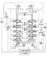
図2は、第一実施例に係る油圧ショベルに搭載される油圧回路の構成例を示す概略図である。なお、図2は、高圧油路、パイロット油路、及び電気駆動・制御系をそれぞれ実線、破線、及び点線で示すものとする。 FIG. 2 is a schematic diagram illustrating a configuration example of a hydraulic circuit mounted on the hydraulic excavator according to the first embodiment. In FIG. 2, the high-pressure oil passage, the pilot oil passage, and the electric drive / control system are indicated by a solid line, a broken line, and a dotted line, respectively.
第一実施例において、油圧回路は、エンジンによって駆動される二つのメインポンプ12L、12Rから、センターバイパス油路40L、40Rのそれぞれを経て油タンクまで圧油を循環させる。
In the first embodiment, the hydraulic circuit circulates the pressure oil from the two
メインポンプ12L、12Rは、高圧油路を介して圧油を制御弁150、流量制御弁151〜160のそれぞれに供給するための装置であり、例えば、斜板式可変容量型油圧ポンプである。なお、メインポンプ12L、12Rのポンプ制御方式には、好適には、ネガティブコントロール制御が採用される。
The
レギュレータ13L、13Rは、メインポンプ12L、12Rの吐出量を制御するための装置であり、例えば、メインポンプ12L、12Rの斜板傾転角を調節することによって、メインポンプ12L、12Rの吐出量を制御する。
The
センターバイパス油路40Lは、流量制御弁151、153、155、157及び158を連通する高圧油路であり、最も下流にある流量制御弁159と圧油タンクとの間にネガティブコントロール絞り20Lを備える。
The center
センターバイパス油路40Rは、制御弁150、流量制御弁152、154、156、159、及び160を連通する高圧油路であり、最も下流にある流量制御弁160と圧油タンクとの間にネガティブコントロール絞り20Rを備える。
The center
メインポンプ12L、12Rが吐出した圧油の流れは、ネガティブコントロール絞り20L、20Rで制限されることとなる。そのため、ネガティブコントロール絞り20L、20Rは、レギュレータ13L、13Rを制御するための制御圧(以下、「ネガコン圧」とする。)を発生させる。
The flow of pressure oil discharged from the
ネガコン圧油路41L、41Rは、ネガティブコントロール絞り20L、20Rの上流で発生させたネガコン圧をレギュレータ13L、13Rに伝達するためのパイロット油路である。
The negative control
レギュレータ13L、13Rは、ネガコン圧に応じてメインポンプ12L、12Rの斜板傾転角を調節することによって、メインポンプ12L、12Rの吐出量を制御する。また、レギュレータ13L、13Rは、導入されるネガコン圧が大きいほどメインポンプ12L、12Rの吐出量を減少させ、導入されるネガコン圧が小さいほどメインポンプ12L、12Rの吐出量を増大させるようにする。
The
具体的には、油圧ショベルにおける油圧アクチュエータが何れも操作されていない場合(以下、「待機モード」とする。)、メインポンプ12L、12Rが吐出する圧油は、センターバイパス油路40L、40Rを通ってネガティブコントロール絞り20L、20Rに至る。そして、メインポンプ12L、12Rが吐出する圧油の流れは、ネガティブコントロール絞り20L、20Rの上流で発生するネガコン圧を増大させる。その結果、レギュレータ13L、13Rは、メインポンプ12L、12Rの吐出量を許容最小吐出量まで減少させ、吐出した圧油がセンターバイパス油路40L、40Rを通過する際の圧力損失(ポンピングロス)を抑制するようにする。
Specifically, when none of the hydraulic actuators in the hydraulic excavator is operated (hereinafter referred to as “standby mode”), the pressure oil discharged from the
一方、油圧ショベルにおける何れかの油圧アクチュエータが操作された場合、メインポンプ12L、12Rが吐出する圧油は、操作対象の油圧アクチュエータに対応する流量制御弁を介して、操作対象の油圧アクチュエータに流れ込む。そして、メインポンプ12L、12Rが吐出する圧油の流れは、ネガティブコントロール絞り20L、20Rに至る量を減少或いは消滅させ、ネガティブコントロール絞り20L、20Rの上流で発生するネガコン圧を低下させる。その結果、低下したネガコン圧を受けるレギュレータ13L、13Rは、メインポンプ12L、12Rの吐出量を増大させ、操作対象の油圧アクチュエータに十分な圧油を循環させ、操作対象の油圧アクチュエータの駆動を確かなものとする。
On the other hand, when any hydraulic actuator in the hydraulic excavator is operated, the pressure oil discharged from the
上述のような構成により、図2の油圧システムは、待機モードにおいては、メインポンプ12L、12Rにおける無駄なエネルギ消費(メインポンプ12L、12Rが吐出する圧油がセンターバイパス油路40L、40Rで発生させるポンピングロス)を抑制することができる。
With the configuration as described above, in the standby mode, the hydraulic system in FIG. 2 consumes unnecessary energy in the
また、図2の油圧システムは、油圧アクチュエータを駆動する場合には、メインポンプ12L、12Rから必要十分な圧油を駆動対象の油圧アクチュエータに確実に供給できるようにする。
In addition, when the hydraulic actuator is driven, the hydraulic system of FIG. 2 can reliably supply necessary and sufficient pressure oil from the
また、レギュレータ13L、13Rは、上述のネガコン圧制御に加え、メインポンプ12L、12Rの吐出圧に応じてメインポンプ12L、12Rの斜板傾転角を調節することによって(全馬力制御によって)、メインポンプ12L、12Rの吐出量を制御するものとする。具体的には、レギュレータ13L、13Rは、メインポンプ12L、12Rの吐出圧が所定値以上となった場合にメインポンプ12L、12Rの斜板傾転角を調節して吐出量を減少させ、吐出圧と吐出量との積で表されるポンプ馬力がエンジンの出力馬力を超えないようにする。
Further, in addition to the negative control pressure control described above, the
制御弁150は、走行直進弁であり、下部走行体2を駆動する左右の走行用油圧モータ(図示せず。)とそれ以外の他の油圧アクチュエータとが同時に操作された場合に作動するスプール弁である。具体的には、制御弁150は、下部走行体2の直進性を高めるべくメインポンプ12Lのみから流量制御弁151及び流量制御弁152のそれぞれに圧油を循環させるために圧油の流れを切り替えることができる。
The
流量制御弁151は、メインポンプ12Lが吐出する圧油を左側走行用油圧モータ(図示せず。)で循環させるために圧油の流れを切り替えるスプール弁であり、流量制御弁152は、メインポンプ12L又は12Rが吐出する圧油を右側走行用油圧モータ(図示せず。)で循環させるために圧油の流れを切り替えるスプール弁である。
The flow
流量制御弁153は、メインポンプ12L又は12Rが吐出する圧油を旋回用油圧モータ(図示せず。)で循環させるために圧油の流れを切り替えるスプール弁である。
The flow
流量制御弁154は、メインポンプ12Rが吐出する圧油をバケットシリンダ9へ供給し、且つ、バケットシリンダ9内の圧油を油タンクへ排出するためのスプール弁である。
The flow
流量制御弁155は、油圧モータ又は油圧シリンダを駆動するために利用可能な予備のスプール弁である。
The
流量制御弁156、157は、メインポンプ12L、12Rが吐出する圧油をブームシリンダ7へ供給し、且つ、ブームシリンダ7内の圧油を油タンクへ排出するために圧油の流れを切り替えるスプール弁である。なお、流量制御弁156は、ブーム操作レバー16Bが操作された場合に常に作動するスプール弁(以下、「第一ブーム流量制御弁」とする。)である。また、流量制御弁157は、ブーム操作レバー16Bが所定のレバー操作量以上で操作された場合にのみ作動するスプール弁(以下、「第二ブーム流量制御弁」とする。)である。
The flow
第一ブーム流量制御弁156は、下げ側位置(図中右側のスプール位置)における、CTポートとPCポートとの間に逆止弁を含む高圧油路156Aを備える。なお、CTポートは、ブームシリンダ7のボトム側油室と油タンクとを繋ぐポートであり、PCポートは、メインポンプ12Rとブームシリンダ7のロッド側油室とを繋ぐポートであり、PTポートは、メインポンプ12Rと油タンクとを繋ぐポートである。また、高圧油路156Aは、ブームシリンダ7のボトム側油室から流出する圧油をブームシリンダ7のロッド側油室に流入させるための再生用高圧油路である。また、再生用高圧油路156Aの開口面積は、第一ブーム流量制御弁156の下げ側位置方向(図の左方向)への変位量に比例するものとする。
The first boom flow
第二ブーム流量制御弁157は、下げ側位置(図中左側のスプール位置)における、PTポートとブームシリンダ7のボトム側油室との間に逆止弁及び絞りを含む高圧油路157Aを備える。なお、高圧油路157Aは、ブームシリンダ7のボトム側油室から流出する圧油をセンターバイパス油路40Lに合流させるための合流用高圧油路である。また、合流用高圧油路157Aの開口面積は、第二ブーム流量制御弁157の下げ側位置方向(図の右方向)への変位量に比例するものとする。
The second boom flow
流量制御弁158、159は、メインポンプ12L、12Rが吐出する圧油をアームシリンダ8へ供給し、且つ、アームシリンダ8内の圧油を油タンクへ排出するために圧油の流れを切り替えるスプール弁である。なお、流量制御弁158は、アーム操作レバー16Aが操作された場合に常に作動する弁(以下、「第一アーム流量制御弁」とする。)である。また、流量制御弁159は、アーム操作レバー16Aが所定のレバー操作量以上で操作された場合にのみ作動する弁(以下、「第二アーム流量制御弁」とする。)である。
The flow
流量制御弁160は、メインポンプ12Rが吐出する圧油をネガティブコントロール絞り20Rまで到達させるか否かを切り替えるスプール弁である。
The flow
アーム操作レバー16Aは、アーム5を操作するための操作装置であって、コントロールポンプ(図示せず。)が吐出する圧油を利用して、レバー操作量に応じたパイロット圧を第一アーム流量制御弁158及び第二アーム流量制御弁159のそれぞれにおける左右何れかのパイロットポートに導入させる。
The
ブーム操作レバー16Bは、ブーム4を操作するための操作装置であって、コントロールポンプが吐出する圧油を利用して、レバー操作量に応じたパイロット圧を第一ブーム流量制御弁156及び第二ブーム流量制御弁157のそれぞれにおける左右何れかのパイロットポートに導入させる。
The
バケット操作レバー16Cは、バケット6を操作するための操作装置であって、コントロールポンプが吐出する圧油を利用して、レバー操作量に応じたパイロット圧を流量制御弁154の左右何れかのパイロットポートに導入させる。
The
アーム開きパイロット圧センサ17Aは、アーム操作量検出部の一例であり、アーム操作レバー16Aにおける開き方向のレバー操作量(レバー操作角度)を圧力として検出する圧力センサであって、検出した値をコントローラ30に対して出力する。
The arm opening
ブーム下げパイロット圧センサ17Bは、ブーム操作量検出部の一例であり、ブーム操作レバー16Bにおける下げ方向のレバー操作量(レバー操作角度)を圧力として検出する圧力センサであって、検出した値をコントローラ30に対して出力する。
The boom lowering pilot pressure sensor 17B is an example of a boom operation amount detection unit, and is a pressure sensor that detects a lever operation amount (lever operation angle) in the lowering direction of the
バケット開きパイロット圧センサ17Cは、バケット操作量検出部の一例であり、バケット操作レバー16Cにおける開き方向のレバー操作量(レバー操作角度)を圧力として検出する圧力センサであって、検出した値をコントローラ30に対して出力する。
The bucket opening
左右走行レバー(又はペダル)及び旋回操作レバー(何れも図示せず。)は、それぞれ、下部走行体2の走行、及び、上部旋回体3の旋回を操作するための操作装置である。これらの操作装置は、アーム操作レバー16A等と同様に、コントロールポンプが吐出する圧油を利用して、レバー操作量(又はペダル操作量)に応じたパイロット圧を左右の走行用油圧モータ及び旋回用油圧モータのそれぞれに対応する流量制御弁の左右何れかのパイロットポートに導入させる。また、これらの操作装置のそれぞれに対する操作者の操作内容(レバー操作方向及びレバー操作量である。)は、圧力センサ17A〜17Cと同様に、対応する圧力センサによって圧力の形で検出され、検出値がコントローラ30に対して出力される。
The left and right traveling levers (or pedals) and the turning operation lever (both not shown) are operation devices for operating the traveling of the
メインリリーフ弁18は、メインポンプ12L又は12Rの吐出圧が所定のリリーフ圧以上となった場合に圧油を油タンクに排出して吐出圧を所定のリリーフ圧未満に制御する安全弁である。
The
リリーフ弁19L、19Rは、ネガティブコントロール絞り20L、20Rの上流におけるネガコン圧が所定のリリーフ圧以上となった場合に圧油を油タンクに排出してネガコン圧を所定のリリーフ圧未満に制御する安全弁である。
The
比例電磁弁21は、第二ブーム流量制御弁157の下げ側(左側)のパイロットポートに作用するパイロット圧を制御するための装置であり、例えば、コントローラ30からの制御指令電流に応じて出力圧を変化させる比例電磁減圧弁である。
The
コントローラ30は、油圧回路を制御するための制御装置であり、例えば、CPU(Central Processing Unit)、RAM(Random Access Memory)、ROM(Read Only Memory)等を備えたコンピュータで構成される。
The
また、コントローラ30は、制御実行判定部300及び合流制御部301のそれぞれに対応するプログラムをROM等の不揮発性記憶媒体から読み出してRAM等の揮発性記憶媒体に展開しながら、それぞれに対応する処理をCPUに実行させる。
In addition, the
具体的には、コントローラ30は、圧力センサ17A〜17C等が出力する検出値を受信し、それら検出値に基づいて制御実行判定部300及び合流制御部301のそれぞれによる処理を実行する。
Specifically, the
その後、コントローラ30は、制御実行判定部300及び合流制御部301のそれぞれの処理結果に応じた制御指令電流を適宜に比例電磁弁21に対して出力する。
Thereafter, the
制御実行判定部300は、掘削アタッチメントによる排土作業、水平戻し作業等の、空中でブーム4を下げ方向に操作しながらアーム5を開き方向に大きく動かすような作業(以下、「排土作業等」とする。)の際に、合流制御部301による第二ブーム流量制御弁157の下げ側位置への変位制御を実行するか否かを判定するための機能要素であり、例えば、アーム操作レバー16Aの開き方向のレバー操作量と、ブーム操作レバー16Bの下げ方向のレバー操作量とに基づいて制御開始条件が成立したか否か(制御解除条件が成立していないか否か)を判定する。
The control
具体的には、制御実行判定部300は、アーム操作レバー16Aの開き方向のレバー操作量が所定の上限側操作領域にあり、かつ、ブーム操作レバー16Bの下げ方向のレバー操作量が所定の中間操作領域又は上限側操作領域にある場合に制御開始条件が成立した(排土作業等の状態にある)ものと判定する。
Specifically, in the control
「上限側操作領域」とは、操作対象を所望の操作方向に操作するために操作レバーを最大レバー操作角度付近まで操作したときのレバー操作量の範囲を意味する。例えば、上限側操作領域は、アーム5を開き方向に操作するためにアーム操作レバー16Aをフル操作したときのアーム操作レバー16Aのレバー操作量を含む。
The “upper limit side operation area” means a range of lever operation amounts when the operation lever is operated to near the maximum lever operation angle in order to operate the operation target in a desired operation direction. For example, the upper limit side operation area includes the lever operation amount of the
「中間操作領域」とは、操作対象を所望の操作方向に緩慢操作するために操作レバーを操作したときのレバー操作量の範囲を意味する。例えば、中間操作領域は、ブーム4を下げ方向に緩慢操作するためにブーム操作レバー16Bを操作したときのブーム操作レバー16Bのレバー操作量を含む。
The “intermediate operation area” means a range of lever operation amounts when the operation lever is operated in order to slowly operate the operation target in a desired operation direction. For example, the intermediate operation region includes a lever operation amount of the
より具体的には、中間操作領域は、土砂を所定場所に排土する操作、水平戻し操作等において、空中でアーム5を開き方向に操作しながらブーム4を下げ方向に操作するためにブーム操作レバー16Bを操作したときのブーム操作レバー16Bのレバー操作量を含む。
More specifically, the intermediate operation region is a boom operation for operating the
また、上限側操作領域は、その下限が中間操作領域の上限と同じになるように設定されてもよく、その下限と中間操作領域の上限との間に一定の間隔を空けるように設定されてもよい。 Further, the upper limit side operation area may be set such that the lower limit thereof is the same as the upper limit of the intermediate operation area, and is set so as to leave a certain interval between the lower limit and the upper limit of the intermediate operation area. Also good.
合流制御部301は、第二ブーム流量制御弁157の下げ側位置方向(図2の右方向)への変位を制御するための機能要素である。
The
具体的には、合流制御部301は、例えば、ブーム操作レバー16Bの下げ方向のレバー操作量とは独立して、第二ブーム流量制御弁157の下げ側(左側)のパイロットポートに作用するパイロット圧を制御し、第二ブーム流量制御弁157の下げ側位置方向(図2の右方向)への変位量を制御する。なお、第二ブーム流量制御弁157の下げ側位置方向(図2の右方向)への変位量は、第二ブーム流量制御弁157の下げ側(左側)のパイロットポートに作用するパイロット圧の大きさに比例するものとする。
Specifically, the merging
より具体的には、合流制御部301は、例えば、制御実行判定部300により制御開始条件が成立していない(制御解除条件が成立した)と判定された場合に比例電磁弁21に対する制御指令電流を最大とし、第二ブーム流量制御弁157の下げ側(左側)のパイロットポートとブーム操作レバー16Bの下げ側パイロット圧油路との間の連通を遮断すると共に、第二ブーム流量制御弁157の下げ側(左側)のパイロットポートをドレン(油タンク)ポートに連通する。これにより、合流制御部301は、第二ブーム流量制御弁157の下げ側位置方向(図2の右方向)への変位を禁止し、ブームシリンダ7のボトム側油室から流出する圧油がセンターバイパス油路40Lに合流するのを禁止する。なお、本実施例では、ブームシリンダ7のボトム側油室から流出する圧油は、ブーム操作レバー16Bが下げ方向に操作されている間、第一ブーム流量制御弁156の再生用高圧油路156Aを通じてブームシリンダ7のロッド側油室に再生される。
More specifically, the
一方で、合流制御部301は、例えば、制御実行判定部300により制御開始条件が成立したと判定された場合に比例電磁弁21に対して所定の大きさの制御指令電流を出力し、ブーム操作レバー16Bの下げ側パイロット圧油路の圧油を制御指令電流に応じた圧力に調整して第二ブーム流量制御弁157の下げ側(左側)のパイロットポートに導入する。なお、ブーム下げパイロット圧は、ブーム操作レバー16Bの下げ方向のレバー操作量の増大とともに増大する傾向を有する。これにより、合流制御部301は、第二ブーム流量制御弁157を下げ側位置方向(図2の右方向)へ変位させ、ブームシリンダ7のボトム側油室から流出する圧油のセンターバイパス油路40Lへの合流を開始させるようにする。なお、本実施例では、ブームシリンダ7のボトム側油室から流出する圧油は、ブームシリンダ7のロッド側油室にも再生される。また、第二ブーム流量制御弁157の下げ側(左側)のパイロットポートに作用するブーム下げパイロット圧は、好適には、あらかじめ設定された一定値(典型的にはより高い値である。)となるように制御される。また、本実施例では、第二ブーム流量制御弁157の下げ側(左側)のパイロットポートに作用するブーム下げパイロット圧は、比例電磁弁21の開故障を考慮してブーム操作レバー16Bの下げ側パイロット圧油路の圧油を元圧として利用しているが、コントロールポンプ(図示せず。)の吐出する圧油を元圧として利用してもよい。なお、この場合、比例電磁弁21は、比例電磁減圧弁ではなく比例電磁弁を用いればよい。
On the other hand, the
また、合流制御部301は、ブームシリンダ7のボトム側油室の圧力に応じて、第二ブーム流量制御弁157の下げ側のパイロットポートに作用するブーム下げパイロット圧を変化させ、第二ブーム流量制御弁157の下げ側位置方向への変位量を変化させるようにしてもよい。
Further, the merging
また、合流制御部301は、ブーム操作レバー16Bの下げ方向のレバー操作量に応じて、第二ブーム流量制御弁157の下げ側のパイロットポートに作用するブーム下げパイロット圧を変化させ、第二ブーム流量制御弁157の下げ側位置方向への変位量を変化させるようにしてもよい。この場合、合流制御部301は、第一ブーム流量制御弁156の下げ側のパイロットポートに作用するブーム下げパイロット圧とは異なるように、第二ブーム流量制御弁157の下げ側のパイロットポートに作用するブーム下げパイロット圧を変化させるようにしてもよい。
In addition, the merging
また、合流制御部301は、ブームシリンダ7のボトム側油室の圧力とブーム操作レバー16Bの下げ方向のレバー操作量とに応じて、第二ブーム流量制御弁157の下げ側位置方向への変位量を変化させるようにしてもよい。
Further, the merging
また、合流制御部301は、建設機械の動作モード(例えば、Hモード、SPモード等である。)、目標エンジン回転数等といった現時点における建設機械の設定内容に応じて、第二ブーム流量制御弁157の下げ側のパイロットポートに作用するブーム下げパイロット圧を変化させるようにしてもよい。
In addition, the merging
また、合流制御部301は、キャビン10内に設置されたタッチパネル等の入力装置(図示せず。)を介した操作者の入力に応じて、第二ブーム流量制御弁157の下げ側のパイロットポートに対するブーム下げパイロット圧の作用が有効となるようにしてもよい。反対に、第二ブーム流量制御弁157の下げ側のパイロットポートに対するブーム下げパイロット圧の作用が無効となるようにしてもよい。
In addition, the
また、第二ブーム流量制御弁157の下げ側(左側)のパイロットポートに作用するブーム下げパイロット圧は、段階的に変化するように制御されてもよく、無段階で線形又は非線形に変化するよう制御されてもよい。
Further, the boom lowering pilot pressure acting on the lower side (left side) pilot port of the second boom flow
また、合流制御部301は、制御実行判定部300により制御開始条件が成立したと判定された後で改めて制御開始条件が成立していない(制御解除条件が成立した)と判定された場合には、第二ブーム流量制御弁157の下げ側(左側)のパイロットポートとブーム操作レバー16Bの下げ側パイロット圧油路との間の連通を遮断すると共に、第二ブーム流量制御弁157の下げ側(左側)のパイロットポートをドレン(油タンク)ポートに連通して、第二ブーム流量制御弁157の下げ側(左側)のパイロットポートに作用するパイロット圧を変化前の状態に戻すようにする。
In addition, when the control
ここで、図3を参照しながら、制御実行判定部300が、掘削アタッチメントによる排土作業等の際に合流制御部301による第二ブーム流量制御弁157の下げ側位置への変位制御を実行するか否かを判定する処理(以下、「制御実行判定処理」とする。)の一例について説明する。なお、図3は、第一実施例に係る油圧ショベルで実行される制御実行判定処理の流れを示すフローチャートであり、この制御実行判定処理は、油圧ショベルが作動している間、継続的に実行されるものとする。なお、制御判定フラグFの初期値(コントローラ30が起動されたときの初期化処理セット値)は「0」であるものとする。
Here, with reference to FIG. 3, the control
最初に、制御実行判定部300は、アーム操作レバー16Aの開き方向のレバー操作量が上限側操作領域にあり、かつ、ブーム操作レバー16Bの下げ方向のレバー操作量が中間操作領域又は上限側操作領域にあるか否かを判定する。
First, in the control
具体的には、制御実行判定部300は、ブーム下げパイロット圧センサ17Bの出力であるブーム下げパイロット圧が所定の閾値β以上であるか否かを判定する(ステップST1)。この場合、ブーム下げパイロット圧が所定の閾値β以上であることは、ブーム操作レバー16Bの上げ方向のレバー操作量が中間操作領域又は上限側操作領域にあることを意味する。
Specifically, control
ブーム下げパイロット圧が閾値β以上であると判定した場合(ステップST1のYES)、制御実行判定部300は、アーム開きパイロット圧センサ17Aの出力であるアーム開きパイロット圧が所定の閾値α以上であるか否かを判定する(ステップST2)。この場合、アーム開きパイロット圧が所定の閾値α以上であることは、アーム操作レバー16Aの開き方向のレバー操作量が上限側操作領域にあることを意味する。
When it is determined that the boom lowering pilot pressure is equal to or higher than the threshold value β (YES in step ST1), the control
アーム開きパイロット圧が閾値α以上であると判定した場合(ステップST2のYES)、制御実行判定部300は、制御開始条件が成立したと判定して制御判定フラグFに「1」をセットする(ステップST3)。
When it is determined that the arm opening pilot pressure is greater than or equal to the threshold value α (YES in step ST2), the control
一方、ブーム下げパイロット圧が閾値β未満であると判定した場合(ステップST1のNO)、制御実行判定部300は、制御開始条件が成立していない(制御解除条件が成立した)と判定して制御判定フラグFに「0」をセットする(ステップST4)。ブーム操作レバー16Bの下げ方向のレバー操作量が中間操作領域及び上限側操作領域の何れにもないと判断できるからである。
On the other hand, when it is determined that the boom lowering pilot pressure is less than the threshold value β (NO in step ST1), the control
また、ブーム下げパイロット圧が閾値β以上であると判定した場合であっても、アーム開きパイロット圧が閾値α未満であると判定した場合には(ステップST2のNO)、制御実行判定部300は、制御開始条件が成立していない(制御解除条件が成立した)と判定して制御判定フラグFに「0」をセットする(ステップST4)。アーム操作レバー16Aの開き方向のレバー操作量が上限側操作領域にないと判断できるからである。
Further, even when it is determined that the boom lowering pilot pressure is equal to or higher than the threshold value β, when it is determined that the arm opening pilot pressure is lower than the threshold value α (NO in step ST2), the control
なお、制御実行判定部300は、アーム開きパイロット圧が閾値α以上であるか否かの判定を行った後で、ブーム下げパイロット圧が閾値β以上であるか否かの判定を行うようにしてもよく、それらの判定を同時に行うようにしてもよい。以下で説明する他の実施例についても同様である。
The control
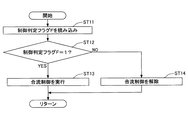
次に、図4を参照しながら、合流制御部301が第二ブーム流量制御弁157を変位させる処理(以下、「合流制御処理」とする。)の一例について説明する。なお、図4は、合流制御処理の流れを示すフローチャートであり、この合流制御処理は、油圧ショベルが作動している間、継続的に実行されるものとする。
Next, an example of a process in which the merging
最初に、合流制御部301は、制御実行判定処理においてセットされた制御判定フラグFを読み込み(ステップST11)、制御判定フラグFが「1」であるか「0」であるかを判定する(ステップST12)。
First, the merging
制御判定フラグFが「1」であると判定した場合(ステップST12のYES)、合流制御部301は、合流制御を実行し(ステップST13)、第二ブーム流量制御弁157を下げ側位置へ変位させる。
When it is determined that the control determination flag F is “1” (YES in step ST12), the merging
具体的には、合流制御部301は、比例電磁弁21に対する制御指令電流を最大値から所定の大きさに減少させ、第二ブーム流量制御弁157の下げ側(左側)のパイロットポートをブーム操作レバー16Bの下げ側パイロット圧油路に連通する。ブーム操作レバー16Bの下げ側パイロット圧油路の圧油を制御指令電流に応じた圧力に調整して第二ブーム流量制御弁157の下げ側(左側)のパイロットポートに導入するためである。なお、第二ブーム流量制御弁157が既に所望の下げ側位置となっている場合、合流制御部301は、第二ブーム流量制御弁157を所望の下げ側位置のまま維持する。
Specifically, the merging
一方、制御判定フラグFが「1」でない(「0」である)と判定した場合(ステップST12のNO)、合流制御部301は、合流制御を解除し(ステップST14)、第二ブーム流量制御弁157を中立位置(図中中央のスプール位置)へ変位させる。
On the other hand, when it is determined that the control determination flag F is not “1” (“0”) (NO in step ST12), the merging
具体的には、合流制御部301は、比例電磁弁21に対する制御指令電流の大きさを最大にし、第二ブーム流量制御弁157の下げ側(左側)のパイロットポートとブーム操作レバー16Bの下げ側パイロット圧油路との間の連通を遮断すると共に、第二ブーム流量制御弁157の下げ側(左側)のパイロットポートをドレン(油タンク)ポートに連通する。なお、第二ブーム流量制御弁157が既に中立位置となっている場合、合流制御部301は、第二ブーム流量制御弁157を中立位置のまま維持する。
Specifically, the
以上の構成により、第一実施例に係る油圧ショベルは、排土作業等の際に合流制御部301による第二ブーム流量制御弁157の下げ側位置への変位制御を実行すると判定した場合に限り、ブーム下げパイロット圧を第二ブーム流量制御弁157の下げ側(左側)のパイロットポートに作用させ、ブームシリンダ7のボトム側油室から流出する圧油をセンターバイパス油路40Lに合流させることができる。その結果、第一実施例に係る油圧ショベルは、ブームシリンダ7のボトム側油室から流出する圧油を、メインポンプ12Lが吐出する圧油とともに、第二ブーム流量制御弁157の下流にある第一アーム流量制御弁158に供給し、排土作業等の際にアーム5で再生利用することができる。排土作業等の間、ブームシリンダ7のボトム側油室の圧力は、アームシリンダ8のロッド側油室の圧力よりも高くなるためである。また、第一実施例に係る油圧ショベルは、ブーム操作レバー16Bの下げ方向のレバー操作量とは独立して、合流用高圧油路157Aを流れる圧油の量を変化させることができるので、排土作業等の間、アーム5の動きを所望の速度に速めることができる。
With the above configuration, the hydraulic excavator according to the first embodiment is limited to the case where it is determined that the displacement control to the lower side position of the second boom flow
また、第一実施例に係る油圧ショベルは、合流用高圧油路157Aを第二ブーム流量制御弁157に内蔵するため、油圧回路の大型化及び複雑化を回避し、コンパクトでかつ安価な構造を採用しながら、上述の効果を実現させることができる。
Further, since the hydraulic excavator according to the first embodiment incorporates the merging high-
次に、図5を参照しながら、本発明の第二実施例に係る油圧ショベルで実行される制御実行判定処理について説明する。なお、図5は、第二実施例に係る油圧ショベルで実行される制御実行判定処理の流れを示すフローチャートであり、この制御実行判定処理は、油圧ショベルが作動している間、継続的に実行されるものとする。 Next, a control execution determination process executed by the hydraulic excavator according to the second embodiment of the present invention will be described with reference to FIG. FIG. 5 is a flowchart showing the flow of the control execution determination process executed by the hydraulic excavator according to the second embodiment. This control execution determination process is continuously executed while the hydraulic excavator is operating. Shall be.
また、図5の制御実行判定処理は、制御開始条件と制御解除条件が異なる点で、図3の制御実行判定処理と相違する。 5 is different from the control execution determination process in FIG. 3 in that the control start condition and the control release condition are different.
そのため、共通点の説明を省略しながら、相違点を詳細に説明するものとする。また、第一の実施例に係る油圧ショベルを説明するために用いた参照符号と同じ参照符号を用いるものとする。 Therefore, the difference will be described in detail while omitting the description of the common points. Further, the same reference numerals as those used for explaining the hydraulic excavator according to the first embodiment are used.
概略的には、図5の制御実行判定処理は、制御開始条件が成立したとの判定が一旦行われると、ブーム下げパイロット圧が閾値β以上である限り、アーム開きパイロット圧にかかわらず、制御判定フラグFを「1」に維持する。すなわち、図5の制御実行判定処理は、制御開始条件が成立したとの判定が一旦行われると、ブーム操作レバー16Bの下げ方向のレバー操作量が中間操作領域又は上限側操作領域にある限り、アーム操作レバー16Aのレバー操作量に関係なく、制御判定フラグFを「1」に維持する。
Schematically, in the control execution determination process of FIG. 5, once it is determined that the control start condition is satisfied, control is performed regardless of the arm opening pilot pressure as long as the boom lowering pilot pressure is equal to or higher than the threshold value β. The determination flag F is maintained at “1”. That is, in the control execution determination process of FIG. 5, once it is determined that the control start condition is satisfied, as long as the lever operation amount in the lowering direction of the
以下、フローチャートを参照しながら、図5の制御実行判定処理を詳細に説明する。 Hereinafter, the control execution determination process of FIG. 5 will be described in detail with reference to a flowchart.
最初に、制御実行判定部300は、ブーム下げパイロット圧が閾値β以上であるか否かを判定する(ステップST21)。
First, the control
ブーム下げパイロット圧が閾値β以上であると判定した場合(ステップST21のYES)、制御実行判定部300は、制御判定フラグFが「0」であるか否かを判定する(ステップST22)。
When it is determined that the boom lowering pilot pressure is equal to or higher than the threshold β (YES in step ST21), the control
制御判定フラグFが「0」でない(「1」である)と判定した場合(ステップST22のNO)、制御実行判定部300は、制御判定フラグFに「1」をセットした状態を維持して(ステップST24)、処理をリターンする。
When it is determined that the control determination flag F is not “0” (“1”) (NO in step ST22), the control
制御判定フラグFが「0」であると判定した場合(ステップST22のYES)、制御実行判定部300は、アーム開きパイロット圧が閾値α以上であるか否かを判定する(ステップST23)。
When it is determined that the control determination flag F is “0” (YES in step ST22), the control
アーム開きパイロット圧が閾値α以上であると判定した場合(ステップST23のYES)、制御実行判定部300は、制御開始条件が成立したと判定して制御判定フラグFに「1」をセットする(ステップST24)。
When it is determined that the arm opening pilot pressure is greater than or equal to the threshold value α (YES in step ST23), the control
アーム開きパイロット圧が閾値α未満であると判定した場合(ステップST23のNO)、制御実行判定部300は、制御開始条件が成立していないと判定して制御判定フラグFに「0」をセットする(「0」のまま維持する)(ステップST25)。
When it is determined that the arm opening pilot pressure is less than the threshold value α (NO in step ST23), the control
一方、ブーム下げパイロット圧が閾値β未満であると判定した場合(ステップST22のNO)、制御実行判定部300は、制御解除条件が成立したと判定して制御判定フラグFに「0」をセットする(ステップ25)。
On the other hand, when it is determined that the boom lowering pilot pressure is less than the threshold β (NO in step ST22), the control
以上の構成により、第二実施例に係る油圧ショベルは、制御開始条件が成立したとの判定が一旦行われると、ブーム下げパイロット圧が閾値β以上である限り、アーム開きパイロット圧にかかわらず、制御判定フラグFを「1」に維持する。すなわち、第二実施例に係る油圧ショベルは、アーム開きパイロット圧の変動によって合流制御部301による第二ブーム流量制御弁157の下げ側位置への変位制御を実行するか否かの判定結果が頻繁に切り替わるのを防止することができる。その結果、第二実施例に係る油圧ショベルは、第二ブーム流量制御弁157の下げ側(左側)のパイロットポートに作用するパイロット圧が頻繁に変化して合流用高圧油路157Aを流れる圧油の量が頻繁に変化し、掘削アタッチメントの動きが振動的になるのを防止することができる。
With the above configuration, the hydraulic excavator according to the second embodiment, once it is determined that the control start condition is satisfied, as long as the boom lowering pilot pressure is equal to or higher than the threshold β, regardless of the arm opening pilot pressure, The control determination flag F is maintained at “1”. That is, the hydraulic excavator according to the second embodiment frequently determines whether or not to execute the displacement control to the lower side position of the second boom flow
次に、図6及び図7を参照しながら、本発明の第三実施例に係る油圧ショベルについて説明する。なお、図6は、第三実施例に係る油圧ショベルに搭載される油圧回路の構成例を示す概略図である。図6は、図2と同様に、高圧油路、パイロット油路、及び電気駆動・制御系をそれぞれ実線、破線、及び点線で示すものとする。また、図7は、第三実施例に係る油圧ショベルで実行される制御実行判定処理の流れを示すフローチャートであり、この制御実行判定処理は、油圧ショベルが作動している間、継続的に実行されるものとする。 Next, a hydraulic excavator according to a third embodiment of the present invention will be described with reference to FIGS. FIG. 6 is a schematic diagram illustrating a configuration example of a hydraulic circuit mounted on the hydraulic excavator according to the third embodiment. In FIG. 6, as in FIG. 2, the high pressure oil passage, the pilot oil passage, and the electric drive / control system are indicated by a solid line, a broken line, and a dotted line, respectively. FIG. 7 is a flowchart showing the flow of the control execution determination process executed by the hydraulic excavator according to the third embodiment. This control execution determination process is continuously executed while the hydraulic excavator is operating. Shall be.
図6は、アームロッド圧センサ17D及びアームボトム圧センサ17Eを備える点で図2の第一実施例に係る油圧回路と相違するがその他の点で共通する。 FIG. 6 differs from the hydraulic circuit according to the first embodiment of FIG. 2 in that it includes an arm rod pressure sensor 17D and an arm bottom pressure sensor 17E, but is common in other points.
また、図7の制御実行判定処理は、アームロッド圧がアームボトム圧以上であるか否かを判定するステップST33を有する点で図3の第一実施例に係る制御実行判定処理と相違するがその他の点で共通する。 The control execution determination process of FIG. 7 is different from the control execution determination process according to the first embodiment of FIG. 3 in that it includes step ST33 for determining whether or not the arm rod pressure is equal to or higher than the arm bottom pressure. It is common in other points.
そのため、共通点の説明を省略しながら、相違点を詳細に説明するものとする。また、第一の実施例に係る油圧ショベルを説明するために用いた参照符号と同じ参照符号を用いるものとする。 Therefore, the difference will be described in detail while omitting the description of the common points. Further, the same reference numerals as those used for explaining the hydraulic excavator according to the first embodiment are used.
アームロッド圧センサ17Dは、アームシリンダ8のロッド側油室における圧力を検出する圧力センサであり、検出した値をコントローラ30に対して出力する。
The arm rod pressure sensor 17 </ b> D is a pressure sensor that detects the pressure in the rod side oil chamber of the arm cylinder 8, and outputs the detected value to the
アームボトム圧センサ17Eは、アームシリンダ8のボトム側油室における圧力を検出する圧力センサであり、検出した値をコントローラ30に対して出力する。
The arm bottom pressure sensor 17 </ b> E is a pressure sensor that detects the pressure in the bottom side oil chamber of the arm cylinder 8, and outputs the detected value to the
制御実行判定部300は、ブーム下げパイロット圧が閾値β以上であると判定し(ステップST31のYES)、アーム開きパイロット圧が閾値α以上であると判定した場合(ステップST32のYES)、アームロッド圧がアームボトム圧以上であるか否かを判定する(ステップST33)。
The control
具体的には、制御実行判定部300は、アームボトム圧センサ17D及びアームロッド圧センサ17Eの出力に基づいてアームロッド圧がアームボトム圧以上であるか否かを判定する。
Specifically, the control
アームロッド圧がアームボトム圧以上であると判定した場合(ステップST33のYES)、制御実行判定部300は、制御開始条件が成立したと判定して制御判定フラグFに「1」をセットする(ステップST34)。
When it is determined that the arm rod pressure is equal to or higher than the arm bottom pressure (YES in step ST33), the control
一方、アームロッド圧がアームボトム圧未満であると判定した場合(ステップST33のNO)、制御実行判定部300は、制御開始条件が成立していない(制御解除条件が成立した)と判定して制御判定フラグFに「0」をセットする(ステップST35)。アーム5が開き方向に操作される場合、アームロッド圧は、メインポンプ12L、12Rが吐出する圧油がアームシリンダ8のロッド側油室に流入するため、アームボトム圧よりも大きくなるからである。
On the other hand, when it is determined that the arm rod pressure is less than the arm bottom pressure (NO in step ST33), the control
このように、制御実行判定部300は、ブーム操作レバー16Bの下げ方向のレバー操作量が中間操作領域又は上限側操作領域にあり、かつ、アーム操作レバー16Aの開き方向のレバー操作量が上限側操作領域にあると判定し、さらに、アームロッド圧がアームボトム圧以上であることを確認した上で、制御開始条件が成立したと判定する。
Thus, the control
なお、第三実施例に係る油圧ショベルは、アームボトム圧センサ17D及びアームロッド圧センサ17Eの代わりに或いはそれらに加えて、ブームボトム圧センサ及びブームロッド圧センサ(何れも図示せず。)を備えるようにしてもよい。この場合、制御実行判定部300は、アームロッド圧がアームボトム圧以上であると判定した上で、ブームボトム圧センサ及びブームロッド圧センサの出力に基づいてブームボトム圧がブームロッド圧以上であると判定した場合に、排土中であると判定するようにしてもよい。また、制御実行判定部300は、アームロッド圧がアームボトム圧以上であると判定する代わりに、ブームボトム圧がブームロッド圧以上であると判定した場合に、制御開始条件が成立したと判定するようにしてもよい。ブーム4が下げ方向に操作される場合、ブームボトム圧は、ブームシリンダ7のボトム側油室から流出する圧油がメータアウト制御されるため、ブームロッド圧よりも大きくなるからである。
The hydraulic excavator according to the third embodiment includes a boom bottom pressure sensor and a boom rod pressure sensor (both not shown) instead of or in addition to the arm bottom pressure sensor 17D and the arm rod pressure sensor 17E. You may make it prepare. In this case, the control
また、第三実施例に係る油圧ショベルは、アームボトム圧センサ17D及びアームロッド圧センサ17Eの代わりに或いはそれらに加えて、バケットボトム圧センサ及びバケットロッド圧センサ(何れも図示せず。)を備えるようにしてもよい。この場合、制御実行判定部300は、アームロッド圧がアームボトム圧以上であると判定した上で、バケットボトム圧センサ及びバケットロッド圧センサの出力に基づいてバケットロッド圧がバケットボトム圧以上であると判定した場合に、制御開始条件が成立したと判定するようにしてもよい。また、制御実行判定部300は、アームロッド圧がアームボトム圧以上であると判定する代わりに、バケットロッド圧がバケットボトム圧以上であると判定した場合に、制御開始条件が成立したと判定するようにしてもよい。バケット6が開き方向に操作される場合、バケットロッド圧は、メインポンプ12L、12Rが吐出する圧油がバケットシリンダ9のロッド側油室に流入するため、バケットボトム圧よりも大きくなるからである。
The hydraulic excavator according to the third embodiment includes a bucket bottom pressure sensor and a bucket rod pressure sensor (both not shown) instead of or in addition to the arm bottom pressure sensor 17D and the arm rod pressure sensor 17E. You may make it prepare. In this case, the control
以上の構成により、第三実施例に係る油圧ショベルで実行される制御実行判定部300は、合流制御部301による第二ブーム流量制御弁157の下げ側位置への変位制御を実行するか否かの判定結果をより信頼性の高いものとすることができる。その結果、制御実行判定部300は、制御開始条件が成立した(制御開始条件が成立していない)との誤判定により排土作業等が行われていないにもかかわらず不用意にアーム5の動きが速められるのを防止することができる。
With the above configuration, whether or not the control
次に、図8を参照しながら、本発明の第四実施例に係る油圧ショベルについて説明する。なお、図8は、第四実施例に係る油圧ショベルで実行される制御実行判定処理の流れを示すフローチャートであり、この制御実行判定処理は、油圧ショベルが作動している間、継続的に実行されるものとする。また、第四実施例に係る油圧ショベルは、図6に示す油圧回路を搭載しているものとする。 Next, a hydraulic excavator according to a fourth embodiment of the present invention will be described with reference to FIG. FIG. 8 is a flowchart showing the flow of the control execution determination process executed by the hydraulic excavator according to the fourth embodiment. This control execution determination process is continuously executed while the hydraulic excavator is operating. Shall be. The hydraulic excavator according to the fourth embodiment is assumed to be equipped with the hydraulic circuit shown in FIG.
図8の制御実行判定処理は、アームロッド圧がアームボトム圧以上であるか否かを判定するステップST44を有する点で図5の第二実施例に係る制御実行判定処理と相違するがその他の点で共通する。 The control execution determination process of FIG. 8 is different from the control execution determination process according to the second embodiment of FIG. 5 in that it has step ST44 for determining whether or not the arm rod pressure is equal to or higher than the arm bottom pressure. In common.
そのため、共通点の説明を省略しながら、相違点を詳細に説明するものとする。また、第一の実施例に係る油圧ショベルを説明するために用いた参照符号と同じ参照符号を用いるものとする。 Therefore, the difference will be described in detail while omitting the description of the common points. Further, the same reference numerals as those used for explaining the hydraulic excavator according to the first embodiment are used.
制御実行判定部300は、制御判定フラグFが「0」であると判定した場合(ステップST42のYES)、アーム開きパイロット圧がα以上か否かを判定する(ステップST43)。
When it is determined that the control determination flag F is “0” (YES in step ST42), the control
アーム開きパイロット圧がα以上であると判定した場合(ステップST43のYES)、制御実行判定部300は、更に、アームロッド圧がアームボトム圧以上であるか否かを判定する(ステップST44)。
When it is determined that the arm opening pilot pressure is greater than or equal to α (YES in step ST43), the control
アームロッド圧がアームボトム圧以上であると判定した場合(ステップST44のYES)、制御実行判定部300は、制御開始条件が成立したと判定して制御判定フラグFに「1」をセットする(ステップST45)。
When it is determined that the arm rod pressure is equal to or higher than the arm bottom pressure (YES in step ST44), the control
一方、アームロッド圧がアームボトム圧未満であると判定した場合(ステップST44のNO)、制御実行判定部300は、制御開始条件が成立していないと判定して制御判定フラグFに「0」をセットする(ステップST46)。アーム5が開き方向に操作される場合、アームロッド圧は、メインポンプ12L、12Rが吐出する圧油がアームシリンダ8のロッド側油室に流入するため、アームボトム圧よりも大きくなるからである。
On the other hand, when it is determined that the arm rod pressure is less than the arm bottom pressure (NO in step ST44), the control
なお、第四実施例に係る油圧ショベルは、第三実施例の場合と同様に、アームボトム圧センサ17D及びアームロッド圧センサ17E(図6参照。)の代わりに或いはそれらに加えて、バケットボトム圧センサ及びバケットロッド圧センサ(何れも図示せず。)、又は、ブームボトム圧センサ及びブームロッド圧センサ(何れも図示せず。)を備えるようにしてもよい。 Note that the hydraulic excavator according to the fourth embodiment is similar to the third embodiment in that a bucket bottom is used instead of or in addition to the arm bottom pressure sensor 17D and the arm rod pressure sensor 17E (see FIG. 6). A pressure sensor and a bucket rod pressure sensor (both not shown), or a boom bottom pressure sensor and a boom rod pressure sensor (both not shown) may be provided.
以上の構成により、第四実施例に係る油圧ショベルに搭載される制御実行判定部300は、制御開始条件が成立したとの仮判定が一旦行われると、ブーム下げパイロット圧が閾値β以上である限り、アーム開きパイロット圧にかかわらず、アームロッド圧がアームボトム圧以上であるか否かにかかわらず制御判定フラグFを「1」に維持する。すなわち、制御実行判定部300は、アーム開きパイロット圧、アームロッド圧、アームボトム圧の変動によって合流制御部301による第二ブーム流量制御弁157の下げ側位置への変位制御を実行するか否かの判定結果が頻繁に切り替わるのを防止することができる。その結果、第四実施例に係る油圧ショベルは、第二ブーム流量制御弁157の下げ側(左側)のパイロットポートに作用するパイロット圧が頻繁に変化して合流用高圧油路157Aを流れる圧油の量が頻繁に変化し、掘削アタッチメントの動きが振動的になるのを防止することができる。
With the above configuration, the control
また、制御実行判定部300は、合流制御部301による第二ブーム流量制
御弁157の下げ側位置への変位制御を実行するか否かの判定結果をより信頼性の高いものとすることができる。その結果、制御実行判定部300は、制御開始条件が成立したとの誤判定により排土作業等が行われていないにもかかわらず不用意にアーム5の動きが速められたり、制御開始条件が成立したとの誤判定により排土作業等が行われているにもかかわらず合流によるブームボトム圧の再生利用が行われなかったりするのを防止することができる。
Further, the control
次に、図9及び図10を参照しながら、本発明の第五実施例に係る油圧ショベルについて説明する。なお、図9は、第五実施例に係る油圧ショベルに搭載される油圧回路の構成例を示す概略図である。図9は、図2及び図6と同様に、高圧油路、パイロット油路、及び電気駆動・制御系をそれぞれ実線、破線、及び点線で示すものとする。また、図10は、第五実施例に係る油圧ショベルで実行される制御実行判定処理の流れを示すフローチャートであり、この制御実行判定処理は、油圧ショベルが作動している間、継続的に実行されるものとする。 Next, a hydraulic excavator according to a fifth embodiment of the present invention will be described with reference to FIGS. FIG. 9 is a schematic diagram showing a configuration example of a hydraulic circuit mounted on the hydraulic excavator according to the fifth embodiment. 9, as in FIGS. 2 and 6, the high pressure oil passage, the pilot oil passage, and the electric drive / control system are indicated by a solid line, a broken line, and a dotted line, respectively. FIG. 10 is a flowchart showing the flow of the control execution determination process executed by the hydraulic excavator according to the fifth embodiment. This control execution determination process is continuously executed while the hydraulic excavator is operating. Shall be.
図9は、吐出圧センサ17F、17Gを備える点で図2の第一実施例に係る油圧回路と相違するがその他の点で共通する。
9 is different from the hydraulic circuit according to the first embodiment of FIG. 2 in that it includes
また、図10の制御実行判定処理は、メインポンプ12L、12Rの吐出圧の双方が所定の閾値ζ以上であるか否かを判定するステップST53を有する点で図3の第一実施例に係る制御実行判定処理と相違するがその他の点で共通する。
Further, the control execution determination process of FIG. 10 according to the first embodiment of FIG. 3 includes a step ST53 for determining whether or not both discharge pressures of the
そのため、共通点の説明を省略しながら、相違点を詳細に説明するものとする。また、第一の実施例に係る油圧ショベルを説明するために用いた参照符号と同じ参照符号を用いるものとする。 Therefore, the difference will be described in detail while omitting the description of the common points. Further, the same reference numerals as those used for explaining the hydraulic excavator according to the first embodiment are used.
吐出圧センサ17Fは、メインポンプ12Lの吐出圧を検出する圧力センサであり、検出した値をコントローラ30に対して出力する。
The
吐出圧センサ17Gは、メインポンプ12Rの吐出圧を検出する圧力センサであり、検出した値をコントローラ30に対して出力する。
The
制御実行判定部300は、ブーム下げパイロット圧が閾値β以上であると判定し(ステップST51のYES)、アーム開きパイロット圧が閾値α以上であると判定した場合(ステップST52のYES)、メインポンプ12L、12Rの吐出圧の双方が閾値ζ以上であるか否かを判定する(ステップST53)。
The control
具体的には、制御実行判定部300は、吐出圧センサ17F、17Gの出力に基づいてメインポンプ12L、12Rの吐出圧の双方が閾値ζ以上であるか否かを判定する。
Specifically, the control
メインポンプ12L、12Rの吐出圧の双方が閾値ζ以上であると判定した場合(ステップST53のYES)、制御実行判定部300は、制御開始条件が成立したと判定して制御判定フラグFに「1」をセットする(ステップST54)。
When it is determined that both the discharge pressures of the
一方、メインポンプ12L、12Rの吐出圧の少なくとも一方が閾値ζ未満であると判定した場合(ステップST53のNO)、制御実行判定部300は、制御開始条件が成立していない(制御開始条件が成立した)と判定して制御判定フラグFに「0」をセットする(ステップST55)。排土作業等の際に、メインポンプ12L、12Rの吐出圧は、圧油をアームシリンダ8のロッド側油室に流入させるために閾値ζ以上となるからである。
On the other hand, when it is determined that at least one of the discharge pressures of the
このように、制御実行判定部300は、ブーム操作レバー16Bの下げ方向のレバー操作量が中間操作領域又は上限側操作領域にあり、かつ、アーム操作レバー16Aの開き方向のレバー操作量が上限側操作領域にあると判定し、さらに、メインポンプ12L、12Rの吐出圧の双方が閾値ζ以上であることを確認した上で、制御開始条件が成立したと判定する。
Thus, the control
以上の構成により、第五実施例に係る油圧ショベルで実行される制御実行判定部300は、合流制御部301による第二ブーム流量制御弁157の下げ側位置への変位制御を実行するか否かの判定結果をより信頼性の高いものとすることができる。その結果、制御実行判定部300は、制御開始条件が成立した(制御解除条件が成立していない)との誤判定により排土作業等が行われていないにもかかわらず不用意にアーム5の動きが速められたり、逆に、排土作業等が行われているにもかかわらず合流によるブームボトム圧の再生利用が行われなかったりするのを防止することができる。
With the above configuration, whether or not the control
次に、図11を参照しながら、本発明の第六実施例に係る油圧ショベルについて説明する。なお、図11は、第六実施例に係る油圧ショベルで実行される制御実行判定処理の流れを示すフローチャートであり、この制御実行判定処理は、油圧ショベルが作動している間、継続的に実行されるものとする。また、第六実施例に係る油圧ショベルは、図9に示す油圧回路を搭載しているものとする。 Next, a hydraulic excavator according to a sixth embodiment of the present invention will be described with reference to FIG. FIG. 11 is a flowchart showing the flow of the control execution determination process executed by the hydraulic excavator according to the sixth embodiment. This control execution determination process is continuously executed while the hydraulic excavator is operating. Shall be. The hydraulic excavator according to the sixth embodiment is assumed to be equipped with the hydraulic circuit shown in FIG.
図11の制御実行判定処理は、メインポンプ12L、12Rの吐出圧の双方が閾値ζ以上であるか否かを判定するステップST64を有する点で図5の第二実施例に係る制御実行判定処理と相違するがその他の点で共通する。
The control execution determination process of FIG. 11 includes a control execution determination process according to the second embodiment of FIG. 5 in that it includes step ST64 for determining whether or not both discharge pressures of the
そのため、共通点の説明を省略しながら、相違点を詳細に説明するものとする。また、第一の実施例に係る油圧ショベルを説明するために用いた参照符号と同じ参照符号を用いるものとする。 Therefore, the difference will be described in detail while omitting the description of the common points. Further, the same reference numerals as those used for explaining the hydraulic excavator according to the first embodiment are used.
制御実行判定部300は、制御判定フラグFが「0」であると判定した場合(ステップST62のYES)、アーム開きパイロット圧がα以上か否かを判定する(ステップST63)。
When it is determined that the control determination flag F is “0” (YES in step ST62), the control
アーム開きパイロット圧がα以上であると判定した場合(ステップST63のYES)、制御実行判定部300は、更に、メインポンプ12L、12Rの吐出圧の双方が閾値ζ以上であるか否かを判定する(ステップST64)。
When it is determined that the arm opening pilot pressure is greater than or equal to α (YES in step ST63), the control
メインポンプ12L、12Rの吐出圧の双方が閾値ζ以上であると判定した場合(ステップST64のYES)、制御実行判定部300は、制御開始条件が成立したと判定して制御判定フラグFに「1」をセットする(ステップST65)。
When it is determined that both the discharge pressures of the
一方、メインポンプ12L、12Rの吐出圧の双方が閾値ζ未満であると判定した場合(ステップST64のNO)、制御実行判定部300は、制御開始条件が成立していないと判定して制御判定フラグFに「0」をセットする(「0」のまま維持する。)(ステップST66)。排土作業等の際に、メインポンプ12L、12Rの吐出圧は、圧油をアームシリンダ8のロッド側油室に流入させるために閾値ζ以上となるからである。
On the other hand, when it is determined that both the discharge pressures of the
以上の構成により、第六実施例に係る油圧ショベルに搭載される制御実行判定部300は、制御開始条件が成立したとの仮判定が一旦行われると、ブーム下げパイロット圧が閾値β以上である限り、アーム開きパイロット圧にかかわらず、メインポンプ12L、12Rの吐出圧の双方が閾値ζ以上であるか否かにかかわらず制御判定フラグFを「1」に維持する。すなわち、制御実行判定部300は、アーム開きパイロット圧、メインポンプ12L、12Rの吐出圧の変動の変動によって合流制御部301による第二ブーム流量制御弁157の下げ側位置への変位制御を実行するか否かの判定結果が頻繁に切り替わるのを防止することができる。その結果、第六実施例に係る油圧ショベルは、第二ブーム流量制御弁157の下げ側(左側)のパイロットポートに作用するパイロット圧が頻繁に変化して合流用高圧油路157Aを流れる圧油の量が頻繁に変化し、掘削アタッチメントの動きが振動的になるのを防止することができる。
With the above configuration, the control
また、制御実行判定部300は、合流制御部301による第二ブーム流量制
御弁157の下げ側位置への変位制御を実行するか否かの判定結果をより信頼性の高いものとすることができる。その結果、制御実行判定部300は、制御開始条件が成立したとの誤判定により排土作業等が行われていないにもかかわらずアーム5の動きが速められたり、制御開始条件が成立していない(制御解除条件が成立した)との誤判定により排土作業等が行われているにもかかわらず合流によるブームボトム圧の再生利用が行われなかったりするのを防止することができる。
Further, the control
以上、本発明の好ましい実施例について詳説したが、本発明は、上述した実施例に制限されることはなく、本発明の範囲を逸脱することなしに上述した実施例に種々の変形及び置換を加えることができる。 Although the preferred embodiments of the present invention have been described in detail above, the present invention is not limited to the above-described embodiments, and various modifications and substitutions can be made to the above-described embodiments without departing from the scope of the present invention. Can be added.
例えば、上述の実施例において、比例電磁弁21は、コントローラ30からの制御指令電流に応じてその出力圧を電気的に変化させるが、アーム開きパイロット圧及びブーム下げパイロット圧に応じてその出力圧を油圧的に変化させるものであってもよい。
For example, in the above-described embodiment, the
また、上述の実施例において、制御実行判定部300は、アームロッド圧がアームボトム圧以上であるか否か、バケットロッド圧がバケットボトム圧以上であるか否か、ブームボトム圧がブームロッド圧以上であるか否か、又は、メインポンプ12L、12Rの吐出圧の双方が所定の閾値ζ以上であるか否かの判定を、合流制御部301による第二ブーム流量制御弁157の下げ側位置への変位制御を実行するか否かの確認のために個別に実行する。しかしながら、制御実行判定部300は、それらの判定を任意に組み合わせて合流制御部301による第二ブーム流量制御弁157の下げ側位置への変位制御を実行するか否かの確認を行うようにしてもよい。さらに、制御実行判定部300は、アーム角度センサ、ブーム角度センサ、バケット角度センサ等の出力に基づいて掘削アタッチメントの姿勢が所定の姿勢であるか否かを判定し、その判定結果を合流制御部301による第二ブーム流量制御弁157の下げ側位置への変位制御を実行するか否かの確認のために用いるようにしてもよい。
In the above-described embodiment, the control
1・・・下部走行体
2・・・旋回機構
3・・・上部旋回体
4・・・ブーム
5・・・アーム
6・・・バケット
7・・・ブームシリンダ
8・・・アームシリンダ
9・・・バケットシリンダ
10・・・キャビン
12L、12R・・・メインポンプ
13L、13R・・・レギュレータ
16A・・・アーム操作レバー
16B・・・ブーム操作レバー
16C・・・バケット操作レバー
17A・・・アーム開きパイロット圧センサ
17B・・・ブーム下げパイロット圧センサ
17C・・・バケット閉じパイロット圧センサ
17D・・・アームロッド圧センサ
17E・・・アームボトム圧センサ
17F、17G・・・吐出圧センサ
18・・・メインリリーフ弁
19L、19R・・・リリーフ弁
20L、20R・・・ネガティブコントロール絞り
21・・・比例電磁弁
30・・・コントローラ
40L、40R・・・センターバイパス油路
41L、41R・・・ネガコン圧油路
150・・・制御弁(走行直進弁)
151〜160・・・流量制御弁
300・・・制御実行判定部
301・・・合流制御部
DESCRIPTION OF
151-160...
Claims (5)
アーム操作量を検出するアーム操作量検出部と、
ブーム操作量を検出するブーム操作量検出部と、
上げ方向のブーム操作量に応じて上げ側位置方向に変位し、下げ方向のブーム操作量に応じて下げ側位置方向に変位する第一ブーム流量制御弁と、
上げ方向のブーム操作量に応じて上げ側位置方向に変位する第二ブーム流量制御弁と、
前記アタッチメントによる所定の作業が行われているか否かを判定する制御実行判定部、及び、前記第二ブーム流量制御弁の下げ側位置方向への変位を下げ方向のブーム操作量とは独立して制御可能な合流制御部を有する制御装置と、を備え、
前記第二ブーム流量制御弁の下げ側位置は、ブームシリンダのボトム側油室から流出する圧油を当該第二ブーム流量制御弁の下げ側位置方向への変位量に応じてセンターバイパス油路に合流させる油路を有し、
前記制御装置は、前記制御実行判定部により、下げ方向のブーム操作量が所定の中間操作領域にあり、かつ、開き方向のアーム操作量が所定の上限側操作領域にあると判定された場合に、前記合流制御部により、前記第二ブーム流量制御弁を下げ側位置に変位させる、
ことを特徴とする建設機械。 A construction machine having an attachment including an arm and a boom,
An arm operation amount detector for detecting an arm operation amount;
A boom operation amount detector for detecting a boom operation amount;
A first boom flow rate control valve that is displaced in the raising-side position direction according to the boom operation amount in the raising direction and is displaced in the lower-side position direction according to the boom operation amount in the lowering direction;
A second boom flow rate control valve that is displaced in the direction of the raising side according to the amount of boom operation in the raising direction;
A control execution determination unit that determines whether or not a predetermined work is being performed by the attachment; and a displacement of the second boom flow rate control valve in the downward side position direction is independent of the amount of boom operation in the downward direction. A control device having a controllable confluence control unit,
The lower side position of the second boom flow rate control valve is such that the pressure oil flowing out from the bottom side oil chamber of the boom cylinder is placed in the center bypass oil passage according to the amount of displacement in the lower side position direction of the second boom flow rate control valve. Has an oil passage to merge,
When the control execution determination unit determines that the boom operation amount in the lowering direction is in a predetermined intermediate operation region and the arm operation amount in the opening direction is in a predetermined upper limit side operation region by the control execution determination unit. The second boom flow rate control valve is displaced to the lowered position by the merge control unit.
Construction machinery characterized by that.
ことを特徴とする請求項1に記載の建設機械。 The merging control unit changes a displacement amount of the second boom flow rate control valve in a lower side position direction according to a pressure of a bottom side oil chamber of the boom cylinder;
The construction machine according to claim 1.
ことを特徴とする請求項1に記載の建設機械。 The merging control unit changes the amount of displacement of the second boom flow control valve in the lower side position direction according to the lower boom operation amount.
The construction machine according to claim 1.
ことを特徴とする請求項1に記載の建設機械。 The merging control unit changes a displacement amount of the second boom flow control valve in a lower side position direction according to a pressure of a bottom side oil chamber of the boom cylinder and a boom operation amount in a lowering direction;
The construction machine according to claim 1.
ことを特徴とする請求項1乃至4の何れか一項に記載の建設機械。 The merging control unit changes the amount of displacement of the second boom flow rate control valve in the lower side position direction stepwise.
The construction machine according to any one of claims 1 to 4 , wherein
Priority Applications (2)
| Application Number | Priority Date | Filing Date | Title |
|---|---|---|---|
| JP2011080730A JP5301601B2 (en) | 2011-03-31 | 2011-03-31 | Construction machinery |
| CN201210049461.9A CN102733443B (en) | 2011-03-31 | 2012-02-29 | Construction machine |
Applications Claiming Priority (1)
| Application Number | Priority Date | Filing Date | Title |
|---|---|---|---|
| JP2011080730A JP5301601B2 (en) | 2011-03-31 | 2011-03-31 | Construction machinery |
Publications (2)
| Publication Number | Publication Date |
|---|---|
| JP2012215016A JP2012215016A (en) | 2012-11-08 |
| JP5301601B2 true JP5301601B2 (en) | 2013-09-25 |
Family
ID=46989697
Family Applications (1)
| Application Number | Title | Priority Date | Filing Date |
|---|---|---|---|
| JP2011080730A Active JP5301601B2 (en) | 2011-03-31 | 2011-03-31 | Construction machinery |
Country Status (2)
| Country | Link |
|---|---|
| JP (1) | JP5301601B2 (en) |
| CN (1) | CN102733443B (en) |
Cited By (1)
| Publication number | Priority date | Publication date | Assignee | Title |
|---|---|---|---|---|
| US10436229B2 (en) | 2014-10-02 | 2019-10-08 | Hitachi Construction Machinery Co., Ltd. | Hydraulic drive system for work machine |
Families Citing this family (9)
| Publication number | Priority date | Publication date | Assignee | Title |
|---|---|---|---|---|
| JP5844761B2 (en) * | 2013-02-22 | 2016-01-20 | 日立建機株式会社 | Hydraulic drive device for hydraulic excavator |
| JP6316776B2 (en) * | 2015-06-09 | 2018-04-25 | 日立建機株式会社 | Hydraulic drive system for work machines |
| JP6644536B2 (en) * | 2015-12-09 | 2020-02-12 | 住友重機械工業株式会社 | Excavator |
| JP6456277B2 (en) * | 2015-12-18 | 2019-01-23 | 日立建機株式会社 | Construction machinery |
| CN108138807B (en) * | 2016-09-28 | 2019-10-25 | 日立建机株式会社 | The pump control system of Work machine |
| JP6732650B2 (en) | 2016-12-22 | 2020-07-29 | 株式会社クボタ | Work machine |
| CN109235534A (en) * | 2018-11-20 | 2019-01-18 | 长安大学 | A kind of hydraulic crawler excavator multipath hydraulic system |
| JP7171475B2 (en) * | 2019-03-11 | 2022-11-15 | 日立建機株式会社 | working machine |
| JP7438082B2 (en) | 2020-11-06 | 2024-02-26 | 川崎重工業株式会社 | hydraulic drive system |
Family Cites Families (13)
| Publication number | Priority date | Publication date | Assignee | Title |
|---|---|---|---|---|
| JPS60179504A (en) * | 1984-02-28 | 1985-09-13 | Mitsubishi Heavy Ind Ltd | Energy recycle circuit |
| WO1993013271A1 (en) * | 1991-12-24 | 1993-07-08 | Hitachi Construction Machinery Co., Ltd. | Hydraulic driving apparatus for construction machines |
| JPH1089317A (en) * | 1996-09-18 | 1998-04-07 | Sumitomo Constr Mach Co Ltd | Boom lowering reproduction circuit of hydraulic excavator |
| JP2003120604A (en) * | 2001-10-11 | 2003-04-23 | Shin Caterpillar Mitsubishi Ltd | Hydraulic circuit |
| JP4606004B2 (en) * | 2003-08-21 | 2011-01-05 | 日立建機株式会社 | Hydraulic drive unit for construction machinery |
| JP4410512B2 (en) * | 2003-08-08 | 2010-02-03 | 日立建機株式会社 | Hydraulic drive |
| JP2005256895A (en) * | 2004-03-10 | 2005-09-22 | Hitachi Constr Mach Co Ltd | Drive control device of hydraulic cylinder for work and hydraulic shovel |
| JP2006070970A (en) * | 2004-09-01 | 2006-03-16 | Shin Caterpillar Mitsubishi Ltd | Hydraulic control circuit for construction machine |
| JP4446851B2 (en) * | 2004-09-27 | 2010-04-07 | 日立建機株式会社 | Hydraulic drive device for work machine |
| JP2010174574A (en) * | 2009-01-30 | 2010-08-12 | Caterpillar Japan Ltd | Working machine |
| JP2010242796A (en) * | 2009-04-01 | 2010-10-28 | Sumitomo (Shi) Construction Machinery Co Ltd | Hydraulic control circuit for construction machine |
| JP5135288B2 (en) * | 2009-05-29 | 2013-02-06 | 日立建機株式会社 | Hydraulic drive unit for construction machinery |
| CN101748767B (en) * | 2009-12-17 | 2011-10-12 | 三一重机有限公司 | Excavating machine starting control method and device thereof |
-
2011
- 2011-03-31 JP JP2011080730A patent/JP5301601B2/en active Active
-
2012
- 2012-02-29 CN CN201210049461.9A patent/CN102733443B/en active Active
Cited By (1)
| Publication number | Priority date | Publication date | Assignee | Title |
|---|---|---|---|---|
| US10436229B2 (en) | 2014-10-02 | 2019-10-08 | Hitachi Construction Machinery Co., Ltd. | Hydraulic drive system for work machine |
Also Published As
| Publication number | Publication date |
|---|---|
| CN102733443A (en) | 2012-10-17 |
| CN102733443B (en) | 2014-10-08 |
| JP2012215016A (en) | 2012-11-08 |
Similar Documents
| Publication | Publication Date | Title |
|---|---|---|
| JP5356477B2 (en) | Construction machinery | |
| JP5301601B2 (en) | Construction machinery | |
| EP2354331B1 (en) | Hydraulic drive device for hydraulic excavator | |
| WO2004083646A1 (en) | Oil pressure circuit for working machines | |
| KR20120123109A (en) | Hydraulic work machine | |
| JP6860519B2 (en) | Construction machinery | |
| JP2018054047A (en) | Hydraulic driving device of work machine | |
| WO2019220954A1 (en) | Hydraulic shovel drive system | |
| WO2021235207A1 (en) | Hydraulic excavator drive system | |
| JP4240075B2 (en) | Hydraulic control circuit of excavator | |
| WO2021039285A1 (en) | Hydraulic system for construction machine | |
| JP5356476B2 (en) | Construction machinery | |
| WO2018021288A1 (en) | Excavator, and control valve for excavator | |
| JP6683641B2 (en) | Hydraulic excavator | |
| JP2013147886A (en) | Construction machine | |
| CN105971043B (en) | Excavator | |
| JP6591370B2 (en) | Hydraulic control equipment for construction machinery | |
| JPH08219107A (en) | Oil hydraulic regenerating device for hydraulic machine | |
| JP5631799B2 (en) | Construction machinery | |
| JP2015178863A (en) | Control system of hybrid construction machine | |
| WO2019064555A1 (en) | Hydraulic drive device of work machine | |
| JP6071821B2 (en) | Hydraulic drive device | |
| JP2000282514A (en) | Hydraulic circuit of construction machine | |
| JP2015172428A (en) | Control system of hybrid construction machine | |
| JP6989548B2 (en) | Construction machinery |
Legal Events
| Date | Code | Title | Description |
|---|---|---|---|
| A977 | Report on retrieval |
Free format text: JAPANESE INTERMEDIATE CODE: A971007 Effective date: 20130329 |
|
| A131 | Notification of reasons for refusal |
Free format text: JAPANESE INTERMEDIATE CODE: A131 Effective date: 20130409 |
|
| A521 | Written amendment |
Free format text: JAPANESE INTERMEDIATE CODE: A523 Effective date: 20130508 |
|
| TRDD | Decision of grant or rejection written | ||
| A01 | Written decision to grant a patent or to grant a registration (utility model) |
Free format text: JAPANESE INTERMEDIATE CODE: A01 Effective date: 20130618 |
|
| A61 | First payment of annual fees (during grant procedure) |
Free format text: JAPANESE INTERMEDIATE CODE: A61 Effective date: 20130619 |
|
| R150 | Certificate of patent or registration of utility model |
Ref document number: 5301601 Country of ref document: JP Free format text: JAPANESE INTERMEDIATE CODE: R150 Free format text: JAPANESE INTERMEDIATE CODE: R150 |