EP1069316B1 - Method and device for controllably feeding hydraulic oil - Google Patents
Method and device for controllably feeding hydraulic oil Download PDFInfo
- Publication number
- EP1069316B1 EP1069316B1 EP99951091A EP99951091A EP1069316B1 EP 1069316 B1 EP1069316 B1 EP 1069316B1 EP 99951091 A EP99951091 A EP 99951091A EP 99951091 A EP99951091 A EP 99951091A EP 1069316 B1 EP1069316 B1 EP 1069316B1
- Authority
- EP
- European Patent Office
- Prior art keywords
- valve
- throttling
- working fluid
- selector
- swing
- Prior art date
- Legal status (The legal status is an assumption and is not a legal conclusion. Google has not performed a legal analysis and makes no representation as to the accuracy of the status listed.)
- Expired - Lifetime
Links
- 238000000034 method Methods 0.000 title claims abstract description 13
- 239000010720 hydraulic oil Substances 0.000 title abstract 4
- 239000012530 fluid Substances 0.000 claims description 65
- 230000033001 locomotion Effects 0.000 claims description 16
- 238000011144 upstream manufacturing Methods 0.000 claims description 6
- 238000010276 construction Methods 0.000 claims description 5
- 230000001276 controlling effect Effects 0.000 claims 6
- 238000010586 diagram Methods 0.000 description 4
- 230000007423 decrease Effects 0.000 description 3
- 230000002452 interceptive effect Effects 0.000 description 2
- 230000007935 neutral effect Effects 0.000 description 2
Images


Classifications
-
- F—MECHANICAL ENGINEERING; LIGHTING; HEATING; WEAPONS; BLASTING
- F15—FLUID-PRESSURE ACTUATORS; HYDRAULICS OR PNEUMATICS IN GENERAL
- F15B—SYSTEMS ACTING BY MEANS OF FLUIDS IN GENERAL; FLUID-PRESSURE ACTUATORS, e.g. SERVOMOTORS; DETAILS OF FLUID-PRESSURE SYSTEMS, NOT OTHERWISE PROVIDED FOR
- F15B11/00—Servomotor systems without provision for follow-up action; Circuits therefor
- F15B11/16—Servomotor systems without provision for follow-up action; Circuits therefor with two or more servomotors
- F15B11/161—Servomotor systems without provision for follow-up action; Circuits therefor with two or more servomotors with sensing of servomotor demand or load
- F15B11/162—Servomotor systems without provision for follow-up action; Circuits therefor with two or more servomotors with sensing of servomotor demand or load for giving priority to particular servomotors or users
-
- E—FIXED CONSTRUCTIONS
- E02—HYDRAULIC ENGINEERING; FOUNDATIONS; SOIL SHIFTING
- E02F—DREDGING; SOIL-SHIFTING
- E02F9/00—Component parts of dredgers or soil-shifting machines, not restricted to one of the kinds covered by groups E02F3/00 - E02F7/00
- E02F9/20—Drives; Control devices
- E02F9/22—Hydraulic or pneumatic drives
- E02F9/2221—Control of flow rate; Load sensing arrangements
- E02F9/2225—Control of flow rate; Load sensing arrangements using pressure-compensating valves
-
- E—FIXED CONSTRUCTIONS
- E02—HYDRAULIC ENGINEERING; FOUNDATIONS; SOIL SHIFTING
- E02F—DREDGING; SOIL-SHIFTING
- E02F9/00—Component parts of dredgers or soil-shifting machines, not restricted to one of the kinds covered by groups E02F3/00 - E02F7/00
- E02F9/20—Drives; Control devices
- E02F9/22—Hydraulic or pneumatic drives
- E02F9/2278—Hydraulic circuits
- E02F9/2282—Systems using center bypass type changeover valves
-
- F—MECHANICAL ENGINEERING; LIGHTING; HEATING; WEAPONS; BLASTING
- F15—FLUID-PRESSURE ACTUATORS; HYDRAULICS OR PNEUMATICS IN GENERAL
- F15B—SYSTEMS ACTING BY MEANS OF FLUIDS IN GENERAL; FLUID-PRESSURE ACTUATORS, e.g. SERVOMOTORS; DETAILS OF FLUID-PRESSURE SYSTEMS, NOT OTHERWISE PROVIDED FOR
- F15B2211/00—Circuits for servomotor systems
- F15B2211/30—Directional control
- F15B2211/305—Directional control characterised by the type of valves
- F15B2211/30505—Non-return valves, i.e. check valves
-
- F—MECHANICAL ENGINEERING; LIGHTING; HEATING; WEAPONS; BLASTING
- F15—FLUID-PRESSURE ACTUATORS; HYDRAULICS OR PNEUMATICS IN GENERAL
- F15B—SYSTEMS ACTING BY MEANS OF FLUIDS IN GENERAL; FLUID-PRESSURE ACTUATORS, e.g. SERVOMOTORS; DETAILS OF FLUID-PRESSURE SYSTEMS, NOT OTHERWISE PROVIDED FOR
- F15B2211/00—Circuits for servomotor systems
- F15B2211/30—Directional control
- F15B2211/31—Directional control characterised by the positions of the valve element
- F15B2211/3105—Neutral or centre positions
- F15B2211/3116—Neutral or centre positions the pump port being open in the centre position, e.g. so-called open centre
-
- F—MECHANICAL ENGINEERING; LIGHTING; HEATING; WEAPONS; BLASTING
- F15—FLUID-PRESSURE ACTUATORS; HYDRAULICS OR PNEUMATICS IN GENERAL
- F15B—SYSTEMS ACTING BY MEANS OF FLUIDS IN GENERAL; FLUID-PRESSURE ACTUATORS, e.g. SERVOMOTORS; DETAILS OF FLUID-PRESSURE SYSTEMS, NOT OTHERWISE PROVIDED FOR
- F15B2211/00—Circuits for servomotor systems
- F15B2211/40—Flow control
- F15B2211/405—Flow control characterised by the type of flow control means or valve
- F15B2211/40515—Flow control characterised by the type of flow control means or valve with variable throttles or orifices
-
- F—MECHANICAL ENGINEERING; LIGHTING; HEATING; WEAPONS; BLASTING
- F15—FLUID-PRESSURE ACTUATORS; HYDRAULICS OR PNEUMATICS IN GENERAL
- F15B—SYSTEMS ACTING BY MEANS OF FLUIDS IN GENERAL; FLUID-PRESSURE ACTUATORS, e.g. SERVOMOTORS; DETAILS OF FLUID-PRESSURE SYSTEMS, NOT OTHERWISE PROVIDED FOR
- F15B2211/00—Circuits for servomotor systems
- F15B2211/40—Flow control
- F15B2211/42—Flow control characterised by the type of actuation
- F15B2211/428—Flow control characterised by the type of actuation actuated by fluid pressure
-
- F—MECHANICAL ENGINEERING; LIGHTING; HEATING; WEAPONS; BLASTING
- F15—FLUID-PRESSURE ACTUATORS; HYDRAULICS OR PNEUMATICS IN GENERAL
- F15B—SYSTEMS ACTING BY MEANS OF FLUIDS IN GENERAL; FLUID-PRESSURE ACTUATORS, e.g. SERVOMOTORS; DETAILS OF FLUID-PRESSURE SYSTEMS, NOT OTHERWISE PROVIDED FOR
- F15B2211/00—Circuits for servomotor systems
- F15B2211/40—Flow control
- F15B2211/455—Control of flow in the feed line, i.e. meter-in control
-
- F—MECHANICAL ENGINEERING; LIGHTING; HEATING; WEAPONS; BLASTING
- F15—FLUID-PRESSURE ACTUATORS; HYDRAULICS OR PNEUMATICS IN GENERAL
- F15B—SYSTEMS ACTING BY MEANS OF FLUIDS IN GENERAL; FLUID-PRESSURE ACTUATORS, e.g. SERVOMOTORS; DETAILS OF FLUID-PRESSURE SYSTEMS, NOT OTHERWISE PROVIDED FOR
- F15B2211/00—Circuits for servomotor systems
- F15B2211/50—Pressure control
- F15B2211/575—Pilot pressure control
- F15B2211/5756—Pilot pressure control for opening a valve
-
- F—MECHANICAL ENGINEERING; LIGHTING; HEATING; WEAPONS; BLASTING
- F15—FLUID-PRESSURE ACTUATORS; HYDRAULICS OR PNEUMATICS IN GENERAL
- F15B—SYSTEMS ACTING BY MEANS OF FLUIDS IN GENERAL; FLUID-PRESSURE ACTUATORS, e.g. SERVOMOTORS; DETAILS OF FLUID-PRESSURE SYSTEMS, NOT OTHERWISE PROVIDED FOR
- F15B2211/00—Circuits for servomotor systems
- F15B2211/70—Output members, e.g. hydraulic motors or cylinders or control therefor
- F15B2211/71—Multiple output members, e.g. multiple hydraulic motors or cylinders
-
- F—MECHANICAL ENGINEERING; LIGHTING; HEATING; WEAPONS; BLASTING
- F15—FLUID-PRESSURE ACTUATORS; HYDRAULICS OR PNEUMATICS IN GENERAL
- F15B—SYSTEMS ACTING BY MEANS OF FLUIDS IN GENERAL; FLUID-PRESSURE ACTUATORS, e.g. SERVOMOTORS; DETAILS OF FLUID-PRESSURE SYSTEMS, NOT OTHERWISE PROVIDED FOR
- F15B2211/00—Circuits for servomotor systems
- F15B2211/70—Output members, e.g. hydraulic motors or cylinders or control therefor
- F15B2211/78—Control of multiple output members
- F15B2211/781—Control of multiple output members one or more output members having priority
Definitions
- the present invention relates to a method of controlling supply of working fluid for an ordinary machine or a construction machine.
- the invention also relates to a control device used for such a method.
- Fig. 3 shows an example of a hydraulic excavator as a construction machine.
- the hydraulic excavator has a lower structure 1 and an upper structure 3, which is rotatably attached to the lower structure 1 with a revolving bearing portion 2 therebetween.
- a front attachment 4 is mounted on the upper structure 3.
- the front attachment 4 includes a boom 5, an arm 6 and a bucket 7.
- the base end of the boom 5 is rotatably fitted to the upper structure 3, while the front end of the boom 5 is rotatably attached to the base end of the arm 6.
- the bucket 7 is rotatably attached to the front end of the arm 6.
- the boom 5, the arm 6 and the bucket 7 are adapted to be rotated by a boom cylinder 5c, an arm cylinder 6c and a bucket cylinder 7c respectively.
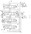
- FIG. 4 An example of conventional swing priority circuits is shown in Fig. 4, wherein working fluid is discharged from a hydraulic pump 10. The working fluid is then divided and fed into a center bypass line 13 and a parallel line 14 in a control valve 12, with a relief valve 11 controlling the pressure of the working fluid to a preset pressure.
- a throttling selector valve dedicated to swinging motion (hereinafter called the swing selector valve) 15, an arm-dedicated throttling selector valve (hereinafter called the arm-dedicated selector valve) 16, and other throttling selector valves 28,29 are disposed in the control valve 12.
- the swing selector valve 15 is adapted to control a revolution motor 3m for revolving the upper structure to the right or the left.
- the other throttling selector valves 28,29 are adapted to control other cylinders of the front attachment 4 and the drive motor of the lower structure 1.
- the swing selector valve 15 is designed to be pilot-operated by a remote-control valve dedicated to controlling hydraulic pressure for swinging motion and adapted to be manually operated with a swing operating lever.
- the arm-dedicated selector valve 16 is designed to be pilot-operated by an oil pressure remote-controlling valve that is dedicated to controlling the arm and adapted to be manually operated with another operating lever.
- the swing selector valve 15 is disposed upstream from the arm-dedicated selector valve 16, and a supply line 17 that leads to the swing selector valve 15 is connected to the parallel line 14, thereby forming a so-called parallel circuit.
- a supply line 18 leading to the arm-dedicated selector valve 16 is connected to the center bypass line 13, thereby forming a so-called tandem circuit.
- a supply line 19 extends between the parallel line 14 and the supply line 18, and a swing priority valve 21 is disposed in the supply line 19.
- the swing priority valve 21 is adapted to be changed over based on external pilot signal pressure fed from a solenoid valve 20, which is of an on/off switching type.
- a solenoid valve 20 When the solenoid valve 20 is off, the external pilot signal pressure that is fed from a pilot pump 22 through the solenoid valve 20 is applied through a pilot line 23 to the swing priority valve 21 and switches said swing priority valve 21 so that the parallel line 14 communicates with the supply line :18.
- the solenoid valve 20 is at the 'on' position, the pilot line 23 communicates with a drain line 24 so that the swing priority valve 21 is at the neutral position as shown in the drawing. Therefore, the parallel line 14 and the supply line 18 are cut of f from each other.
- the revolution motor 3m when the revolution motor 3m operates in sync with the arm cylinder 6c, the working fluid fed to the arm cylinder 6c is limited by means of a bypass notch 25 of the swing selector valve 15, and the working fluid fed to the revolution motor 3m, which serves to revolve the upper structure 3, travels from the parallel line 14 to the arm cylinder 6c through the supply line 17 and a supply notch 27.
- This mechanism is a so-called swing priority circuit, which is particularly effective for, for example, digging a groove by conducting an arm-in operation while pushing the bucket against the wall of the groove with revolving motion.
- the manner of controlling the swing priority valve 21 is on/off control by the solenoid valve 20. Therefore, as described above, in case the swing priority valve 21 is in the blocked state in the swing priority circuit, the bypass notch 25 of the swing selector valve 15 limits the working fluid during the period when the revolution motor 3m operates in sync with the arm cylinder 6c. Along the nearly entire stroke of the swing selector valve 15, the opening-area of the bypass notch 25 is normally much smaller than the opening-area of the bypass notch 27 as shown in Fig. 5 so as to ensure a sufficient supply of working fluid to the revolution motor 3m during swinging operation.
- an object of the present invention is to make effective use of working fluid fed from a pump to a plurality of throttling selector valves (15,16,28,29). Another object of the invention is to make the machine more convenient to operate by ensuring smooth interactive operation among a plurality of hydraulic actuators.
- the present invention provides a method of controlling supply of a working fluid according to claim 1.
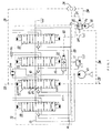
- Fig. 1 shows an example of swing priority circuits, wherein a control valve 12 is connected to a hydraulic pump 10, which is a pump installed in a hydraulic excavator.
- the control valve 12 contains a plurality of throttling selector valves adapted to control respectively working fluid fed from the hydraulic pump 10 to a plurality of hydraulic actuators that operate movable elements of the hydraulic excavator, such as the lower structure 1, the upper structure 3, the boom 5, the arm 6 and the bucket 7.
- the aforementioned plurality of hydraulic actuators comprise a drive motor (not shown), a revolution motor 3m, a boom cylinder 5c, an arm cylinder 6c and a bucket cylinder 7c or the like.
- the throttling selector valves mentioned above are spool valves which are respectively adapted to control the directions and the flow rates of the working fluid fed to these hydraulic actuators.
- the present embodiment includes a swing throttling selector valve (hereinafter called swing selector valve) 15 adapted to control swinging motions of the hydraulic excavator by controlling the working fluid fed to the revolution motor 3m.
- Said swing selector valve 15 is referred to as the first throttling selector valve in the claims and other parts of this specification.
- An arm-dedicated throttling selector valve (hereinafter called arm-dedicated selector valve) 16 serving as the second throttling selector valve referred to in the claims and other parts of this specification is disposed downstream from the swing selector valve 15 and adapted to control action of the arm of the hydraulic excavator by controlling the working fluid fed to the arm cylinder 6c.
- other throttling selector valves 28,29 which are adapted to commonly receive working fluid from the hydraulic pump 10, are disposed upstream from the swing selector valve 15 and downstream from the arm-dedicated selector valve 16 respectively.
- a center bypass line 13, a parallel line 14 and a tank line 30, too, are provided in the control valve 12.
- the center bypass line 13 is adapted to sequentially supply the selector valves 28,15,16,29 with working fluid discharged from the hydraulic pump 10.
- the parallel line 14 branches off from the center line 14 and adapted to feed working fluid discharged from the hydraulic pump 10 to the selector valves 28,15,16,29 independently from the center bypass line 13.
- the tank line 30 communicates with an oil tank.
- a supply line 18, which branches off from the center bypass line 13, is connected to a supply port of the arm-dedicated selector valve 16, while another supply line 19, which branches of f from the parallel line 14, is also connected to the supply port of the arm-dedicated selector valve 16.
- a swing priority valve 21 that serves as a priority valve to give priority to swinging motion over arm movement is disposed in the supply line 19.
- the swing priority valve 21 is a pilot-operated throttle valve designed such that in accordance with increase in external pilot signal pressure the valve gradually opens from the fully closed state, where the spring is at the original, returned position.
- a quantity of working fluid fed to the swing selector valve 15 is given priority over a quantity of working fluid fed to the arm-dedicated selector valve 16 by adjusting the opening of the swing priority valve 21.
- a pilot-operated pressure reducing valve (hereinafter simply called the pressure reducing valve) 31 is disposed in a pilot line 23 between the swing priority valve 21 and a pilot pump 22 which serves to supply the swing priority valve 21 with pilot pressure.
- Said pressure reducing valve 31 serves as a control means for steadily controlling the swing priority valve 21 from the open position to the closed position in accordance with the degree of operation of the swing selector valve 21.
- the pressure reducing valve 31 is designed to be controlled based on swing-dedicated remote control pressure output from a swing operating valve (not Shown) to pilot lines 32,33 of the swing selector valve 15.
- Said swing operating valve is an oil pressure remote-control valve dedicated to controlling hydraulic pressure for swinging motion and adapted to be operated by the operator of the hydraulic excavator by using a lever.
- Pilot lines 34,35 branch of f respectively from the pilot lines 32,33, which extend from the remote-control valve dedicated to controlling hydraulic pressure for swinging motion and serve to pilot-control the swing selector valve 15.
- the pilot lines 34,35 communicate with a pilot chamber of the pressure reducing valve 31, via a shuttle valve 36 and a pilot line 37. Because of the shuttle valve 36, pilot pressure generated in either pilot line 34/35 is applied to the pressure reducing valve 31 through the pilot line 37.
- the pressure reducing valve 31 is controlled in such a manner that its delivery pressure P1, which serves as the external pilot signal pressure applied to the swing priority valve 21, is reduced according to degree of pilot operation of the swing selector valve 15, in other words increase in swing-dedicated remote control pressure, which is used to pilot-operate the swing selector valve 15.
- the pressure reducing valve 31 is designed such that its inlet pressure P0 from the pilot pump 22 is reduced in inverse proportion to swing-dedicated remote control pressure and output as delivery pressure P1
- the pressure reducing valve 31 automatically and steadily adjusts the swing priority valve 21 from the fully open state to the fully closed state by means of delivery pressure P1 which is gradually reduced.
- the center bypass line 13 is substantially narrowed by means of the bypass notch 25 of the swing selector valve 15 so that the quantity of the working fluid fed from the supply line 18 to the supply port of the arm-dedicated selector valve 16 is drastically reduced.
- a sufficient quantity of working fluid is ensured to be fed from the parallel line 14 through the swing priority valve 21 and the supply line 19 to the supply port of the arm-dedicated selector valve 16. Therefore, there is no possibility of radical reduction in the quantity of working fluid fed to the arm-dedicated selector valve 16 occurring during minute swinging operation.
- the working fluid supplied from the hydraulic pump 10 is efficiently used as it is steadily and efficiently distributed to the revolution motor 3m, and the arm-cylinder 6c, which are controlled by the swing selector valve 15 and the arm-dedicated selector valve 16 respectively. Furthermore, as the hydraulic fluid distributed from the swing priority valve 21 to the arm-dedicated selector valve 16 can gradually be reduced from the maximum flow rate in accordance with the degree of operation of the swing selector valve 15, smooth interactive operation is ensured among a plurality of hydraulic actuators. Thus, operation of the machine is made more effective.
- the invention provides a variable swing priority circuit which is capable of appropriately controlling the degree of priority given to swinging motion according to degree of operation of the swing operation lever.
- the swing priority circuit of a hydraulic excavator of an oil pressure remote-control type includes a pilot-operated pressure reducing valve 31 which is disposed in the pilot line 23 of the swing priority valve 21 and adapted to be controlled by remote control pressure dedicated to lateral swinging motion, which pressure is fed from a remote-control valve dedicated to controlling hydraulic pressure for swinging motion.
- the present invention provides a variable-type swing priority circuit which is capable of making the machine easier to maneuver by appropriately controlling the degree of priority given to swinging motion according to degree of operation of the swing operation lever.
- the aforementioned swing priority valve 21 is disposed in the swing priority circuit adapted to give priority to the swing selector valve 15, which serves as the first throttling selector valve, over the arm-dedicated selector valve 16 serving as the second throttling selector valve.
- the swing priority valve 21 may be disposed in a circuit that is adapted to give priority to the first throttling selector valve that is not the swing selector valve 15 over another throttling selector valve that is not the arm-dedicated selector valve 16.
- a method and a device for controlling supply of working fluid according to the invention are applicable to not only a hydraulic excavator but also construction machines of other types, such as a bulldozer, a loader, or the like.
- the invention is also applicable to an ordinary machine of a wide variety of types wherein a plurality of hydraulic actuators are respectively controlled by a plurality of throttling selector valves.
Landscapes
- Engineering & Computer Science (AREA)
- General Engineering & Computer Science (AREA)
- Physics & Mathematics (AREA)
- Fluid Mechanics (AREA)
- Mining & Mineral Resources (AREA)
- Civil Engineering (AREA)
- Structural Engineering (AREA)
- Mechanical Engineering (AREA)
- Operation Control Of Excavators (AREA)
- Fluid-Pressure Circuits (AREA)
- Jib Cranes (AREA)
Abstract
Description
- The present invention relates to a method of controlling supply of working fluid for an ordinary machine or a construction machine. The invention also relates to a control device used for such a method.
- Fig. 3 shows an example of a hydraulic excavator as a construction machine. The hydraulic excavator has a lower structure 1 and an
upper structure 3, which is rotatably attached to the lower structure 1 with a revolving bearingportion 2 therebetween. A front attachment 4 is mounted on theupper structure 3. The front attachment 4 includes a boom 5, an arm 6 and a bucket 7. The base end of the boom 5 is rotatably fitted to theupper structure 3, while the front end of the boom 5 is rotatably attached to the base end of the arm 6. The bucket 7 is rotatably attached to the front end of the arm 6. The boom 5, the arm 6 and the bucket 7 are adapted to be rotated by aboom cylinder 5c, an arm cylinder 6c and a bucket cylinder 7c respectively. - An example of conventional swing priority circuits is shown in Fig. 4, wherein working fluid is discharged from a hydraulic pump 10. The working fluid is then divided and fed into a center bypass line 13 and a
parallel line 14 in acontrol valve 12, with a relief valve 11 controlling the pressure of the working fluid to a preset pressure. - A throttling selector valve dedicated to swinging motion (hereinafter called the swing selector valve) 15, an arm-dedicated throttling selector valve (hereinafter called the arm-dedicated selector valve) 16, and other
throttling selector valves control valve 12. Theswing selector valve 15 is adapted to control arevolution motor 3m for revolving the upper structure to the right or the left. The otherthrottling selector valves - The
swing selector valve 15 is designed to be pilot-operated by a remote-control valve dedicated to controlling hydraulic pressure for swinging motion and adapted to be manually operated with a swing operating lever. The arm-dedicated selector valve 16 is designed to be pilot-operated by an oil pressure remote-controlling valve that is dedicated to controlling the arm and adapted to be manually operated with another operating lever. - The
swing selector valve 15 is disposed upstream from the arm-dedicated selector valve 16, and asupply line 17 that leads to theswing selector valve 15 is connected to theparallel line 14, thereby forming a so-called parallel circuit. - A
supply line 18 leading to the arm-dedicated selector valve 16 is connected to the center bypass line 13, thereby forming a so-called tandem circuit. - A
supply line 19 extends between theparallel line 14 and thesupply line 18, and aswing priority valve 21 is disposed in thesupply line 19. Theswing priority valve 21 is adapted to be changed over based on external pilot signal pressure fed from asolenoid valve 20, which is of an on/off switching type. When thesolenoid valve 20 is off, the external pilot signal pressure that is fed from a pilot pump 22 through thesolenoid valve 20 is applied through apilot line 23 to theswing priority valve 21 and switches saidswing priority valve 21 so that theparallel line 14 communicates with the supply line :18. When thesolenoid valve 20 is at the 'on' position, thepilot line 23 communicates with adrain line 24 so that theswing priority valve 21 is at the neutral position as shown in the drawing. Therefore, theparallel line 14 and thesupply line 18 are cut of f from each other. - When the
solenoid valve 20 is switched on, the working fluid is fed to the arm cylinder 6c solely from the center bypass line 13, because thesupply line 19 is blocked by theswing priority valve 21, which is at the neutral position. - Therefore, when the
revolution motor 3m operates in sync with the arm cylinder 6c, the working fluid fed to the arm cylinder 6c is limited by means of abypass notch 25 of theswing selector valve 15, and the working fluid fed to therevolution motor 3m, which serves to revolve theupper structure 3, travels from theparallel line 14 to the arm cylinder 6c through thesupply line 17 and asupply notch 27. - In other words, the fluid is preferentially fed to the swing system. This mechanism is a so-called swing priority circuit, which is particularly effective for, for example, digging a groove by conducting an arm-in operation while pushing the bucket against the wall of the groove with revolving motion.
- When the
solenoid valve 20 is turned off, the external pilot signal pressure fed from the pilot pump 22 changes over theswing priority valve 21 so that theparallel line 14 communicates with thesupply line 18. Therefore, if thesolenoid valve 20 is at the 'off' position when therevolution motor 3m operates in sync with the arm cylinder 6c, swing priority does not work, because theparallel line 14 feeds working fluid to the arm cylinder 6c. - According to the prior art described above, the manner of controlling the
swing priority valve 21 is on/off control by thesolenoid valve 20. Therefore, as described above, in case theswing priority valve 21 is in the blocked state in the swing priority circuit, thebypass notch 25 of theswing selector valve 15 limits the working fluid during the period when therevolution motor 3m operates in sync with the arm cylinder 6c. Along the nearly entire stroke of theswing selector valve 15, the opening-area of thebypass notch 25 is normally much smaller than the opening-area of thebypass notch 27 as shown in Fig. 5 so as to ensure a sufficient supply of working fluid to therevolution motor 3m during swinging operation. - As a result, in cases where there is a change in the degree of operation of the swing operating lever, in other words the distance of shifting the
swing selector valve 15, the working fluid fed through thesupply line 18 to the arm-dedicated selector valve 16 is considerably reduced by thebypass notch 25 almost regardless of the degree of operation of the swing operating lever. Thus, the working fluid fed to the arm cylinder 6c is reduced to an extremely small quantity. - The way a machine is supposed to work is that when the degree at operation or the swing operating lever is increased, the quantity of the hydraulic fluid supplied to the arm cylinder 6c should increase accordingly. Likewise, when the degree of operation of the swing operating lever is reduced, the quantity of the hydraulic fluid supplied to the arm cylinder 6c should decrease accordingly. In other words, it is desirable that the working fluid fed from the hydraulic pump 10 be effectively and efficiently used. In reality, however, it is difficult with the conventional art to achieve effective use of working fluid. During minute swinging operation, too, the conventional art presents a problem in that large restriction at the
bypass notch 25 hinders quick movement of the arm cylinder 6c. - In order to solve the above problem, an object of the present invention is to make effective use of working fluid fed from a pump to a plurality of throttling selector valves (15,16,28,29). Another object of the invention is to make the machine more convenient to operate by ensuring smooth interactive operation among a plurality of hydraulic actuators.
- The applicant may be further enlightened as to the state of the art by reference to
US 4977928 with respect to which claims 1 and 5 of the present application are characterized. - In order to alleviate the technical problems explained above the present invention provides a method of controlling supply of a working fluid according to claim 1.
- Further according to the present invention there is provided a working fluid supply control device according to claim 5.
-
- Fig. 1 is a circuit diagram of a control device for controlling supply of working fluid according to an embodiment of the present invention; Fig 2 is a characteristic diagram showing operation characteristics of a pilot-operated pressure reducing valve used in said control device; Fig. 3 is a side view of a hydraulic excavator as a construction machine; Fig 4 is a hydraulic circuit diagram of a conventional control device for controlling supply of working fluid; and Fig. 5 is a characteristic diagram showing opening characteristics of a swing selector valve used in said conventional control device.
- Next, an embodiment of the present invention is explained hereunder, referring to Figs. 1 through 3. In the description hereunder, elements and components similar to those of the conventional device shown in Fig. 4 are identified with the same reference numerals (11-29), explanation of which may be omitted.
- Fig. 1 shows an example of swing priority circuits, wherein a
control valve 12 is connected to a hydraulic pump 10, which is a pump installed in a hydraulic excavator. Thecontrol valve 12 contains a plurality of throttling selector valves adapted to control respectively working fluid fed from the hydraulic pump 10 to a plurality of hydraulic actuators that operate movable elements of the hydraulic excavator, such as the lower structure 1, theupper structure 3, the boom 5, the arm 6 and the bucket 7. - The aforementioned plurality of hydraulic actuators comprise a drive motor (not shown), a
revolution motor 3m, aboom cylinder 5c, an arm cylinder 6c and a bucket cylinder 7c or the like. The throttling selector valves mentioned above are spool valves which are respectively adapted to control the directions and the flow rates of the working fluid fed to these hydraulic actuators. - The present embodiment includes a swing throttling selector valve (hereinafter called swing selector valve) 15 adapted to control swinging motions of the hydraulic excavator by controlling the working fluid fed to the revolution motor 3m. Said
swing selector valve 15 is referred to as the first throttling selector valve in the claims and other parts of this specification.
An arm-dedicated throttling selector valve (hereinafter called arm-dedicated selector valve) 16 serving as the second throttling selector valve referred to in the claims and other parts of this specification is disposed downstream from theswing selector valve 15 and adapted to control action of the arm of the hydraulic excavator by controlling the working fluid fed to the arm cylinder 6c. Furthermore, otherthrottling selector valves swing selector valve 15 and downstream from the arm-dedicated selector valve 16 respectively. - A center bypass line 13, a
parallel line 14 and atank line 30, too, are provided in thecontrol valve 12. The center bypass line 13 is adapted to sequentially supply theselector valves parallel line 14 branches off from thecenter line 14 and adapted to feed working fluid discharged from the hydraulic pump 10 to theselector valves tank line 30 communicates with an oil tank. - Between the
swing selector valve 15 and the arm-dedicated selector valve 16, asupply line 18, which branches off from the center bypass line 13, is connected to a supply port of the arm-dedicated selector valve 16, while anothersupply line 19, which branches of f from theparallel line 14, is also connected to the supply port of the arm-dedicated selector valve 16. - A
swing priority valve 21 that serves as a priority valve to give priority to swinging motion over arm movement is disposed in thesupply line 19. Theswing priority valve 21 is a pilot-operated throttle valve designed such that in accordance with increase in external pilot signal pressure the valve gradually opens from the fully closed state, where the spring is at the original, returned position. Thus, a quantity of working fluid fed to theswing selector valve 15 is given priority over a quantity of working fluid fed to the arm-dedicated selector valve 16 by adjusting the opening of theswing priority valve 21. - Instead of a
conventional solenoid valve 20 shown in Fig. 4, a pilot-operated pressure reducing valve (hereinafter simply called the pressure reducing valve) 31 is disposed in apilot line 23 between theswing priority valve 21 and a pilot pump 22 which serves to supply theswing priority valve 21 with pilot pressure. Saidpressure reducing valve 31 serves as a control means for steadily controlling theswing priority valve 21 from the open position to the closed position in accordance with the degree of operation of theswing selector valve 21. - The
pressure reducing valve 31 is designed to be controlled based on swing-dedicated remote control pressure output from a swing operating valve (not Shown) topilot lines 32,33 of theswing selector valve 15. Said swing operating valve is an oil pressure remote-control valve dedicated to controlling hydraulic pressure for swinging motion and adapted to be operated by the operator of the hydraulic excavator by using a lever.Pilot lines 34,35 branch of f respectively from thepilot lines 32,33, which extend from the remote-control valve dedicated to controlling hydraulic pressure for swinging motion and serve to pilot-control theswing selector valve 15. The pilot lines 34,35 communicate with a pilot chamber of thepressure reducing valve 31, via ashuttle valve 36 and a pilot line 37. Because of theshuttle valve 36, pilot pressure generated in eitherpilot line 34/35 is applied to thepressure reducing valve 31 through the pilot line 37. - As shown in Fig. 2, the
pressure reducing valve 31 is controlled in such a manner that its delivery pressure P1, which serves as the external pilot signal pressure applied to theswing priority valve 21, is reduced according to degree of pilot operation of theswing selector valve 15, in other words increase in swing-dedicated remote control pressure, which is used to pilot-operate theswing selector valve 15. As thepressure reducing valve 31 is designed such that its inlet pressure P0 from the pilot pump 22 is reduced in inverse proportion to swing-dedicated remote control pressure and output as delivery pressure P1, thepressure reducing valve 31 automatically and steadily adjusts theswing priority valve 21 from the fully open state to the fully closed state by means of delivery pressure P1 which is gradually reduced. To be more specific, when the swing-dedicated remote control pressure of theswing selector valve 15 changes from low to high, delivery pressure P1 of thepressure reducing valve 31 is gradually reduced accordingly. As a result, theswing priority valve 21, on which the delivery pressure P1 works as external pilot signal pressure, is gradually closed from the fully open state in accordance with the decrease of the delivery pressure P1 so that the working fluid fed through theswing priority valve 21 to the arm-dedicatedselector valve 16 is gradually throttled down. - When the
swing selector valve 15 starts up, the center bypass line 13 is substantially narrowed by means of thebypass notch 25 of theswing selector valve 15 so that the quantity of the working fluid fed from thesupply line 18 to the supply port of the arm-dedicatedselector valve 16 is drastically reduced. However, because of the function of thepressure reducing valve 31 described above, a sufficient quantity of working fluid is ensured to be fed from theparallel line 14 through theswing priority valve 21 and thesupply line 19 to the supply port of the arm-dedicatedselector valve 16. Therefore, there is no possibility of radical reduction in the quantity of working fluid fed to the arm-dedicatedselector valve 16 occurring during minute swinging operation. - Thus, the working fluid supplied from the hydraulic pump 10 is efficiently used as it is steadily and efficiently distributed to the
revolution motor 3m, and the arm-cylinder 6c, which are controlled by theswing selector valve 15 and the arm-dedicatedselector valve 16 respectively. Furthermore, as the hydraulic fluid distributed from theswing priority valve 21 to the arm-dedicatedselector valve 16 can gradually be reduced from the maximum flow rate in accordance with the degree of operation of theswing selector valve 15, smooth interactive operation is ensured among a plurality of hydraulic actuators. Thus, operation of the machine is made more effective. - To be more specific, when the
swing selector valve 15 of the hydraulic excavator is minutely operated, a sufficiently quantity of working fluid is fed through theswing priority valve 21 to the arm-dedicatedselector valve 16, thereby allowing the arm 6 to be quickly moved while minute swinging operation is underway. Thus, the machine is made more convenient in such an operation as digging a groove with the front attachment 4. - Next, the function of the embodiment shown in Figs. 1 and 2 is explained.
- Referring to Fig. 1, when remote control pressure of the
swing selector valve 15 is applied to eitherpilot line 34 or 35 during operation for lateral revolution, the remote control pressure passes through the correspondingpilot line 34 or 35 and is applied to thepressure reducing valve 31 via theshuttle valve 36 and the pilot line 37 so that the external pilot signal pressure applied to theswing priority valve 21 is reduced according to the remote control pressure of theswing selector valve 15 as indicated in characteristics shown in Fig. 2. - For example, when remote control pressure of the
swing selector valve 15 changes from low to high, external pilot signal pressure to theswing priority valve 21 changes from high to low. Therefore, when the swing operation lever is gradually engaged, the switching pressure to theswing priority valve 21 gradually decreases so that theswing priority valve 21 is gradually closed from the fully open state. When the swing operation lever is shifted to the maximum operating position, theswing priority valve 21 is fully closed. In other words, according to degree of operation of the swing operation lever, the quantity of hydraulic fluid fed from theparallel line 14 to thesupply line 19 of the arm cylinder 6c can easily be controlled by using theswing priority valve 21. - Therefore, in cases where the degree of operation of the swing operation lever gradually changes from small to large during conjunctional movement of the
revolution motor 3m and the arm cylinder 6c, the quantity of oil fed from thesupply line 19 to the arm cylinder 6c gradually changes from a great quantity to a small quantity. As the hydraulic fluid fed from the hydraulic pump 10 is thus always utilized effectively, the embodiment is free from the problem of "not capable of rapidly moving the arm during minute swinging operation", which problem is common to conventional arts. In other words, the invention provides a variable swing priority circuit which is capable of appropriately controlling the degree of priority given to swinging motion according to degree of operation of the swing operation lever. - As described above, instead of conventional on/off control of the
swing priority valve 21 by switching a solenoid valve, the swing priority circuit of a hydraulic excavator of an oil pressure remote-control type according to the invention includes a pilot-operatedpressure reducing valve 31 which is disposed in thepilot line 23 of theswing priority valve 21 and adapted to be controlled by remote control pressure dedicated to lateral swinging motion, which pressure is fed from a remote-control valve dedicated to controlling hydraulic pressure for swinging motion. As a result of such a configuration, the present invention provides a variable-type swing priority circuit which is capable of making the machine easier to maneuver by appropriately controlling the degree of priority given to swinging motion according to degree of operation of the swing operation lever. - According to the embodiment described above, the aforementioned
swing priority valve 21 is disposed in the swing priority circuit adapted to give priority to theswing selector valve 15, which serves as the first throttling selector valve, over the arm-dedicatedselector valve 16 serving as the second throttling selector valve. However, theswing priority valve 21 may be disposed in a circuit that is adapted to give priority to the first throttling selector valve that is not theswing selector valve 15 over another throttling selector valve that is not the arm-dedicatedselector valve 16. - A method and a device for controlling supply of working fluid according to the invention are applicable to not only a hydraulic excavator but also construction machines of other types, such as a bulldozer, a loader, or the like. The invention is also applicable to an ordinary machine of a wide variety of types wherein a plurality of hydraulic actuators are respectively controlled by a plurality of throttling selector valves.
Claims (7)
- A method of controlling supply of working fluid, which method calls for:feeding working fluid from a pump (10) to:characterized bydelivering working fluid from the pump (10) to a centre line (13) through which the working fluid passes from the pump to a plurality of throttle selector valves (15,16,28,29),delivering working fluid to a parallel line (14), from the centre line (13),
the passing the working fluid through the centre line to be delivered sequentially to each of the throttle selector valves (15,16,28,29),
delivering the working fluid to each of said throttling selector valves (28, 15, 16, 29) without passing through any one of the downstream throttling selector valves (12,15,16,28), and
feeding working fluid from the pump (10) to a first relatively downstream one of the throttling control valves (15) by way of the parallel line (14) controlled according to the degree of operation of a one of the second relatively upstream throttling control valve (16). - A method according to claim 1 comprising the step of controlling the supply of working fluid to the relatively upstream one of the throttling control valves (16) by means of a priority valve (21) which prioritizes working fluid supply to the downstream one of the throttling control valves (15).
- A method according to claim 2 comprising the step of delivering pilot pressure to the priority valve (21) by means of a pilot operated pressure reducing valve (31) which steadily controls the priority valve from the open position to the closed position in accordance with the operation of the downstream throttling control valve (15).
- A method of controlling supply of working fluid according to claim 3 wherein the method is implemented in a construction machine wherein the hydraulic actuators include at least actuators of a revolving system and actuators of a working equipment system, and said method calls for :the first, downstream one of the throttling selector valves (15) is dedicated to the revolving system, andthe second, upstream one of the selector valves (16) is dedicated to the working equipment system, so that the quantity of the working fluid fed to the throttling selector valve dedicated to the working equipment system is throttle-controlled according to the degree of operation of the throttling selector valve dedicated to the revolving system.
- A working fluid supply control device comprising:a pump (10) adapted to discharge working fluid;a plurality of hydraulic actuators (3m,6c) adapted to be operated by the working fluid;a plurality of throttling selector valves (15,16,28,29) for respectively controlling the working fluid fed from the pump (10) to said plurality of hydraulic actuators (3m,6c); characterized in that there is provided:a center bypass line (13) for supplying working fluid from the pump (10) sequentially through said plurality of throttling selector valves (15,16,28,29);a parallel line (14) for supplying each said plurality of throttling selector valves (15,16,28,29) in sequence with the working fluid discharged from the pump (10) without said working fluid passing through an upstream one of said throttling selector valves (15,16,28,29);a supply line (18) branching off from the center bypass line (13) at a point between the first throttling selector valve (15), and the second throttling selector valve (16), and located downstream from said first throttling selector valve, said supply line (18) connected to a supply port of the second throttling selector valve (16);a separate supply line (19) branching off from the parallel line (14) and connected to the supply port of the second throttling selector valve (16);a priority valve (21) disposed in said separate supply line (19) and designed such that the degree of opening-area of the priority valve (21) is adjusted to give priority to the quantity of the hydraulic fluid fed to the first throttling selector valve (15) over the quantity of the hydraulic fluid fed to the second throttling selector valve (16); anda control means (31) adapted to steadily adjust the priority valve (21) from the fully open state to the fully closed state in accordance with the degree of operation of the first throttling selector valve (15).
- A working fluid supply control device as claimed in claim 5, wherein: the first throttling selector valve (15) is a swing-dedicated throttling selector valve (15) for controlling swinging motion of a hydraulic excavator;
the second throttling selector valve (16) is an arm-dedicated throttling selector valve for controlling action of the arm of a hydraulic excavator; and
the priority valve (21) is a swing priority valve for giving priority to swinging motion over action of the arm. - A working fluid supply control device as claimed in claim 5 or claim 6, wherein:the swing priority valve (21) of the working fluid supply control device is a pilot-operated throttle valve which is adapted to gradually open from the fully closed position, where the spring is at the return position, in accordance with increase of external pilot signal pressure; andthe control means is a pilot-operated pressure reducing valve (31) adapted to be controlled in such a manner that its outlet pressure, which serves as external pilot signal pressure applied to the priority valve (21), is reduced according to increase in remote control pressure for pilot-operating the first throttling selector valve (15).
Applications Claiming Priority (3)
| Application Number | Priority Date | Filing Date | Title |
|---|---|---|---|
| JP02753699A JP3545626B2 (en) | 1999-02-04 | 1999-02-04 | Hydraulic oil supply control device |
| JP2753699 | 1999-02-04 | ||
| PCT/JP1999/005934 WO2000046514A1 (en) | 1999-02-04 | 1999-10-27 | Method and device for controllably feeding hydraulic oil |
Publications (3)
| Publication Number | Publication Date |
|---|---|
| EP1069316A1 EP1069316A1 (en) | 2001-01-17 |
| EP1069316A4 EP1069316A4 (en) | 2006-01-18 |
| EP1069316B1 true EP1069316B1 (en) | 2007-12-12 |
Family
ID=12223833
Family Applications (1)
| Application Number | Title | Priority Date | Filing Date |
|---|---|---|---|
| EP99951091A Expired - Lifetime EP1069316B1 (en) | 1999-02-04 | 1999-10-27 | Method and device for controllably feeding hydraulic oil |
Country Status (6)
| Country | Link |
|---|---|
| US (1) | US6581506B1 (en) |
| EP (1) | EP1069316B1 (en) |
| JP (1) | JP3545626B2 (en) |
| KR (1) | KR100483749B1 (en) |
| DE (1) | DE69937733T2 (en) |
| WO (1) | WO2000046514A1 (en) |
Families Citing this family (11)
| Publication number | Priority date | Publication date | Assignee | Title |
|---|---|---|---|---|
| JP2002155907A (en) * | 2000-11-22 | 2002-05-31 | Shin Caterpillar Mitsubishi Ltd | Priority circuits in work machines |
| JP3952994B2 (en) * | 2003-06-13 | 2007-08-01 | コベルコ建機株式会社 | Construction machinery |
| KR101243494B1 (en) * | 2005-12-29 | 2013-03-13 | 두산산업차량 주식회사 | Apparatus for locking hydraulic actuators of industrial vehicles |
| JP4783393B2 (en) * | 2008-04-15 | 2011-09-28 | 住友建機株式会社 | Hydraulic control equipment for construction machinery |
| JP5079827B2 (en) * | 2010-02-10 | 2012-11-21 | 日立建機株式会社 | Hydraulic drive device for hydraulic excavator |
| EP2725239B1 (en) * | 2011-06-27 | 2016-10-19 | Volvo Construction Equipment AB | Hydraulic control valve for construction machinery |
| WO2013008965A1 (en) * | 2011-07-12 | 2013-01-17 | 볼보 컨스트럭션 이큅먼트 에이비 | Flow control valve for construction machinery |
| JP5978985B2 (en) * | 2012-12-26 | 2016-08-24 | コベルコ建機株式会社 | Hydraulic control device and construction machine equipped with the same |
| JP6225035B2 (en) * | 2014-01-21 | 2017-11-01 | 川崎重工業株式会社 | Fluid pressure system |
| JP6915436B2 (en) * | 2017-08-04 | 2021-08-04 | コベルコ建機株式会社 | Swivel type hydraulic work machine |
| US20260002342A1 (en) * | 2022-03-15 | 2026-01-01 | Kawasaki Jukogyo Kabushiki Kaisha | Hydraulic drive apparatus |
Family Cites Families (9)
| Publication number | Priority date | Publication date | Assignee | Title |
|---|---|---|---|---|
| US3920034A (en) * | 1973-05-07 | 1975-11-18 | Tomco Inc | Proportional bypass valve having variable area orifice control means |
| JPS5833652A (en) * | 1981-08-25 | 1983-02-26 | Kobe Steel Ltd | Oil-pressure circuit for oil-pressure shovel |
| JPS58176327A (en) * | 1982-04-06 | 1983-10-15 | Kayaba Ind Co Ltd | Oil pressure controller |
| JPS6246802U (en) * | 1985-09-12 | 1987-03-23 | ||
| SE8803181D0 (en) * | 1988-09-09 | 1988-09-09 | Atlas Copco Ab | HYDRAULIC DRIVING SYSTEM WITH A PRIORITY FUNCTION FOR HYDRAULIC MOTORS |
| US4977928A (en) * | 1990-05-07 | 1990-12-18 | Caterpillar Inc. | Load sensing hydraulic system |
| KR950019256A (en) * | 1993-12-30 | 1995-07-22 | 김무 | Heavy-duty hydraulic circuit with swing variable priority |
| JP3606976B2 (en) * | 1995-12-26 | 2005-01-05 | 日立建機株式会社 | Hydraulic control system for hydraulic working machine |
| US5768973A (en) * | 1996-12-27 | 1998-06-23 | Cochran; Gary | Hydraulic line and valve assembly for construction vehicle auxiliary implements |
-
1999
- 1999-02-04 JP JP02753699A patent/JP3545626B2/en not_active Expired - Fee Related
- 1999-10-27 DE DE69937733T patent/DE69937733T2/en not_active Expired - Lifetime
- 1999-10-27 KR KR10-2000-7010913A patent/KR100483749B1/en not_active Expired - Fee Related
- 1999-10-27 US US09/647,722 patent/US6581506B1/en not_active Expired - Lifetime
- 1999-10-27 EP EP99951091A patent/EP1069316B1/en not_active Expired - Lifetime
- 1999-10-27 WO PCT/JP1999/005934 patent/WO2000046514A1/en not_active Ceased
Also Published As
| Publication number | Publication date |
|---|---|
| US6581506B1 (en) | 2003-06-24 |
| DE69937733T2 (en) | 2008-12-04 |
| KR20010042348A (en) | 2001-05-25 |
| EP1069316A4 (en) | 2006-01-18 |
| WO2000046514A1 (en) | 2000-08-10 |
| DE69937733D1 (en) | 2008-01-24 |
| JP2000227104A (en) | 2000-08-15 |
| JP3545626B2 (en) | 2004-07-21 |
| KR100483749B1 (en) | 2005-04-18 |
| EP1069316A1 (en) | 2001-01-17 |
Similar Documents
| Publication | Publication Date | Title |
|---|---|---|
| US5148676A (en) | Confluence valve circuit of a hydraulic excavator | |
| US6164069A (en) | Hydraulic drive system for construction machine | |
| KR101155717B1 (en) | Apparatus for controlling the boom-swing combined motion of an excavator | |
| EP1662151B1 (en) | Hydraulic drive apparatus | |
| US6241212B1 (en) | Hose rupture control valve unit | |
| EP1069316B1 (en) | Method and device for controllably feeding hydraulic oil | |
| US11649610B2 (en) | Hydraulic system of construction machine | |
| US20190169819A1 (en) | Shovel and control valve for shovel | |
| JPS6323401B2 (en) | ||
| JPH0452329A (en) | Hydraulic control circuit for hydraulic excavator | |
| US10072396B2 (en) | Working machine control system | |
| US6205781B1 (en) | Fluid control system including a work element and a valve arrangement for selectively supplying pressurized fluid thereto from two pressurized fluid sources | |
| EP0705984B1 (en) | Variable priority device | |
| JPH0672437B2 (en) | Hydraulic circuit of hydraulic shovel | |
| KR0169880B1 (en) | Boom ascending and revolution velocity control devices of dredger | |
| JPH01250531A (en) | Oil-pressure control circuit for working machine | |
| JPH068641B2 (en) | Hydraulic circuit | |
| EP0704630B1 (en) | Variable priority device for heavy construction equipment | |
| KR200257578Y1 (en) | A flow rate controlling apparatus for operating boom of an excavator | |
| KR100198155B1 (en) | Arm working oil remaking device of excavator | |
| JP2010065413A (en) | Hydraulic control circuit of working machine | |
| JPH0579060A (en) | Hydraulic circuit of hydraulic shovel | |
| JP2010065733A (en) | Hydraulic control circuit for working machine | |
| JP2846532B2 (en) | Hydraulic control device for construction machinery | |
| JP2685870B2 (en) | Hydraulic circuit of work machine |
Legal Events
| Date | Code | Title | Description |
|---|---|---|---|
| PUAI | Public reference made under article 153(3) epc to a published international application that has entered the european phase |
Free format text: ORIGINAL CODE: 0009012 |
|
| AK | Designated contracting states |
Kind code of ref document: A1 Designated state(s): AT BE CH CY DE DK ES FI FR GB GR IE IT LI LU MC NL PT SE |
|
| 17P | Request for examination filed |
Effective date: 20010207 |
|
| RBV | Designated contracting states (corrected) |
Designated state(s): DE IT |
|
| A4 | Supplementary search report drawn up and despatched |
Effective date: 20051205 |
|
| GRAP | Despatch of communication of intention to grant a patent |
Free format text: ORIGINAL CODE: EPIDOSNIGR1 |
|
| GRAS | Grant fee paid |
Free format text: ORIGINAL CODE: EPIDOSNIGR3 |
|
| GRAA | (expected) grant |
Free format text: ORIGINAL CODE: 0009210 |
|
| AK | Designated contracting states |
Kind code of ref document: B1 Designated state(s): DE IT |
|
| REF | Corresponds to: |
Ref document number: 69937733 Country of ref document: DE Date of ref document: 20080124 Kind code of ref document: P |
|
| PLBE | No opposition filed within time limit |
Free format text: ORIGINAL CODE: 0009261 |
|
| STAA | Information on the status of an ep patent application or granted ep patent |
Free format text: STATUS: NO OPPOSITION FILED WITHIN TIME LIMIT |
|
| 26N | No opposition filed |
Effective date: 20080915 |
|
| PGFP | Annual fee paid to national office [announced via postgrant information from national office to epo] |
Ref country code: DE Payment date: 20091022 Year of fee payment: 11 |
|
| PGFP | Annual fee paid to national office [announced via postgrant information from national office to epo] |
Ref country code: IT Payment date: 20091021 Year of fee payment: 11 |
|
| REG | Reference to a national code |
Ref country code: DE Ref legal event code: R119 Ref document number: 69937733 Country of ref document: DE Effective date: 20110502 |
|
| PG25 | Lapsed in a contracting state [announced via postgrant information from national office to epo] |
Ref country code: IT Free format text: LAPSE BECAUSE OF NON-PAYMENT OF DUE FEES Effective date: 20101027 |
|
| PG25 | Lapsed in a contracting state [announced via postgrant information from national office to epo] |
Ref country code: DE Free format text: LAPSE BECAUSE OF NON-PAYMENT OF DUE FEES Effective date: 20110502 |