EP1661687B1 - Filière d'extrudeuse avec ajustement de l'ouverture de la filière - Google Patents
Filière d'extrudeuse avec ajustement de l'ouverture de la filière Download PDFInfo
- Publication number
- EP1661687B1 EP1661687B1 EP05025941A EP05025941A EP1661687B1 EP 1661687 B1 EP1661687 B1 EP 1661687B1 EP 05025941 A EP05025941 A EP 05025941A EP 05025941 A EP05025941 A EP 05025941A EP 1661687 B1 EP1661687 B1 EP 1661687B1
- Authority
- EP
- European Patent Office
- Prior art keywords
- axis
- spherical
- bearing element
- face
- die head
- Prior art date
- Legal status (The legal status is an assumption and is not a legal conclusion. Google has not performed a legal analysis and makes no representation as to the accuracy of the status listed.)
- Not-in-force
Links
- 238000001125 extrusion Methods 0.000 title claims description 27
- 230000007246 mechanism Effects 0.000 claims abstract description 14
- 239000000463 material Substances 0.000 claims description 13
- 239000004033 plastic Substances 0.000 claims description 12
- 238000000465 moulding Methods 0.000 claims description 8
- 230000009471 action Effects 0.000 claims description 6
- 238000004519 manufacturing process Methods 0.000 claims description 3
- 230000000717 retained effect Effects 0.000 claims 1
- 239000003000 extruded plastic Substances 0.000 abstract description 2
- 230000013011 mating Effects 0.000 abstract 1
- 230000002349 favourable effect Effects 0.000 description 3
- 230000009467 reduction Effects 0.000 description 3
- 230000008719 thickening Effects 0.000 description 3
- 230000008901 benefit Effects 0.000 description 2
- 230000008859 change Effects 0.000 description 2
- 230000002411 adverse Effects 0.000 description 1
- 238000013459 approach Methods 0.000 description 1
- 230000005540 biological transmission Effects 0.000 description 1
- 230000006835 compression Effects 0.000 description 1
- 238000007906 compression Methods 0.000 description 1
- 238000010276 construction Methods 0.000 description 1
- 230000003247 decreasing effect Effects 0.000 description 1
- 230000000694 effects Effects 0.000 description 1
Images

Classifications
-
- B—PERFORMING OPERATIONS; TRANSPORTING
- B29—WORKING OF PLASTICS; WORKING OF SUBSTANCES IN A PLASTIC STATE IN GENERAL
- B29C—SHAPING OR JOINING OF PLASTICS; SHAPING OF MATERIAL IN A PLASTIC STATE, NOT OTHERWISE PROVIDED FOR; AFTER-TREATMENT OF THE SHAPED PRODUCTS, e.g. REPAIRING
- B29C48/00—Extrusion moulding, i.e. expressing the moulding material through a die or nozzle which imparts the desired form; Apparatus therefor
- B29C48/25—Component parts, details or accessories; Auxiliary operations
- B29C48/30—Extrusion nozzles or dies
- B29C48/32—Extrusion nozzles or dies with annular openings, e.g. for forming tubular articles
- B29C48/325—Extrusion nozzles or dies with annular openings, e.g. for forming tubular articles being adjustable, i.e. having adjustable exit sections
- B29C48/327—Extrusion nozzles or dies with annular openings, e.g. for forming tubular articles being adjustable, i.e. having adjustable exit sections with centering means
-
- B—PERFORMING OPERATIONS; TRANSPORTING
- B29—WORKING OF PLASTICS; WORKING OF SUBSTANCES IN A PLASTIC STATE IN GENERAL
- B29C—SHAPING OR JOINING OF PLASTICS; SHAPING OF MATERIAL IN A PLASTIC STATE, NOT OTHERWISE PROVIDED FOR; AFTER-TREATMENT OF THE SHAPED PRODUCTS, e.g. REPAIRING
- B29C48/00—Extrusion moulding, i.e. expressing the moulding material through a die or nozzle which imparts the desired form; Apparatus therefor
- B29C48/03—Extrusion moulding, i.e. expressing the moulding material through a die or nozzle which imparts the desired form; Apparatus therefor characterised by the shape of the extruded material at extrusion
- B29C48/09—Articles with cross-sections having partially or fully enclosed cavities, e.g. pipes or channels
-
- B—PERFORMING OPERATIONS; TRANSPORTING
- B29—WORKING OF PLASTICS; WORKING OF SUBSTANCES IN A PLASTIC STATE IN GENERAL
- B29C—SHAPING OR JOINING OF PLASTICS; SHAPING OF MATERIAL IN A PLASTIC STATE, NOT OTHERWISE PROVIDED FOR; AFTER-TREATMENT OF THE SHAPED PRODUCTS, e.g. REPAIRING
- B29C48/00—Extrusion moulding, i.e. expressing the moulding material through a die or nozzle which imparts the desired form; Apparatus therefor
- B29C48/25—Component parts, details or accessories; Auxiliary operations
- B29C48/252—Drive or actuation means; Transmission means; Screw supporting means
- B29C48/2528—Drive or actuation means for non-plasticising purposes, e.g. dosing unit
-
- B—PERFORMING OPERATIONS; TRANSPORTING
- B29—WORKING OF PLASTICS; WORKING OF SUBSTANCES IN A PLASTIC STATE IN GENERAL
- B29C—SHAPING OR JOINING OF PLASTICS; SHAPING OF MATERIAL IN A PLASTIC STATE, NOT OTHERWISE PROVIDED FOR; AFTER-TREATMENT OF THE SHAPED PRODUCTS, e.g. REPAIRING
- B29C48/00—Extrusion moulding, i.e. expressing the moulding material through a die or nozzle which imparts the desired form; Apparatus therefor
- B29C48/25—Component parts, details or accessories; Auxiliary operations
- B29C48/30—Extrusion nozzles or dies
- B29C48/32—Extrusion nozzles or dies with annular openings, e.g. for forming tubular articles
- B29C48/325—Extrusion nozzles or dies with annular openings, e.g. for forming tubular articles being adjustable, i.e. having adjustable exit sections
-
- B—PERFORMING OPERATIONS; TRANSPORTING
- B29—WORKING OF PLASTICS; WORKING OF SUBSTANCES IN A PLASTIC STATE IN GENERAL
- B29C—SHAPING OR JOINING OF PLASTICS; SHAPING OF MATERIAL IN A PLASTIC STATE, NOT OTHERWISE PROVIDED FOR; AFTER-TREATMENT OF THE SHAPED PRODUCTS, e.g. REPAIRING
- B29C48/00—Extrusion moulding, i.e. expressing the moulding material through a die or nozzle which imparts the desired form; Apparatus therefor
- B29C48/25—Component parts, details or accessories; Auxiliary operations
- B29C48/92—Measuring, controlling or regulating
-
- B—PERFORMING OPERATIONS; TRANSPORTING
- B29—WORKING OF PLASTICS; WORKING OF SUBSTANCES IN A PLASTIC STATE IN GENERAL
- B29C—SHAPING OR JOINING OF PLASTICS; SHAPING OF MATERIAL IN A PLASTIC STATE, NOT OTHERWISE PROVIDED FOR; AFTER-TREATMENT OF THE SHAPED PRODUCTS, e.g. REPAIRING
- B29C2948/00—Indexing scheme relating to extrusion moulding
- B29C2948/92—Measuring, controlling or regulating
- B29C2948/92504—Controlled parameter
- B29C2948/92609—Dimensions
- B29C2948/92647—Thickness
-
- B—PERFORMING OPERATIONS; TRANSPORTING
- B29—WORKING OF PLASTICS; WORKING OF SUBSTANCES IN A PLASTIC STATE IN GENERAL
- B29C—SHAPING OR JOINING OF PLASTICS; SHAPING OF MATERIAL IN A PLASTIC STATE, NOT OTHERWISE PROVIDED FOR; AFTER-TREATMENT OF THE SHAPED PRODUCTS, e.g. REPAIRING
- B29C2948/00—Indexing scheme relating to extrusion moulding
- B29C2948/92—Measuring, controlling or regulating
- B29C2948/92504—Controlled parameter
- B29C2948/92609—Dimensions
- B29C2948/92666—Distortion, shrinkage, dilatation, swell or warpage
-
- B—PERFORMING OPERATIONS; TRANSPORTING
- B29—WORKING OF PLASTICS; WORKING OF SUBSTANCES IN A PLASTIC STATE IN GENERAL
- B29C—SHAPING OR JOINING OF PLASTICS; SHAPING OF MATERIAL IN A PLASTIC STATE, NOT OTHERWISE PROVIDED FOR; AFTER-TREATMENT OF THE SHAPED PRODUCTS, e.g. REPAIRING
- B29C49/00—Blow-moulding, i.e. blowing a preform or parison to a desired shape within a mould; Apparatus therefor
- B29C49/02—Combined blow-moulding and manufacture of the preform or the parison
- B29C49/04—Extrusion blow-moulding
- B29C49/04108—Extrusion blow-moulding extruding several parisons parallel to each other at the same time
Definitions
- Such an extrusion head is from the JP 60-105520 known.
- US 4,472,129 shows an extrusion head, in which a nozzle head is articulated via spherical surfaces. To the nozzle head engage two adjusting rods, which are arranged relative to a central axis of the extrusion head diametrically to each other and parallel to the central axis. The adjusting rods extend in bores of the extrusion head and protrude on an upper side of the same and are driven axially displaceable there via actuating cylinder.
- the DE 35 05 83 7 A1 discloses an extrusion head for making tubular molded articles of extrudable plastic material. It comprises a housing which forms an axis. The housing has a first bore that forms a first inner surface and is centered on the axle. The extrusion head further includes a nozzle head having a second bore defining a second inner surface terminating at a nozzle exit end. Furthermore, the extrusion head comprises a sleeve which extends in the first bore of the housing and in the second bore of the nozzle head along the axis. The quill has an outer surface and ends at the nozzle exit end.
- a gap is formed through which the plastic material is conveyed to form the tubular shaped article, wherein the tubular shaped article emerges from the nozzle head at the nozzle exit end.
- the extrusion head still belongs a joint arrangement comprising mutually guided spherical surfaces.
- the first spherical surface is assigned to a first bearing element and the second to a second bearing element.
- the second bearing element is connected to the nozzle head.
- the second bearing element is held with its spherical surface in contact with the spherical surface of the first bearing element via a spring arrangement. It is provided a location mechanism over which the nozzle head is pivotally adjustable on all sides.
- This actuating mechanism provides a servo motor whose drive axis is parallel to the axis of the extrusion head runs.
- the motor is used to drive an eccentric shaft with the interposition of a reduction gear.
- an eccentrically arranged to the drive shaft pin is mounted, which carries a roller. This role is supported on the outer circumference of the extended second bearing element.
- Four such drives are arranged distributed on the circumference of the second bearing element, so that an all-round pivot adjustment can take place.
- the EP 0 873 845 B1 describes an extrusion head for the production of tubular shaped articles made of extrudable plastic material.
- the extrusion head comprises a housing forming a first axis on which a first bore forming a first inner surface is centered. It further includes a nozzle head having a second bore forming a second inner surface which adjoins the first bore along the axis with the first inner surface and terminates at a nozzle exit end.
- a quill extends along the axis.
- This quill has an outer surface and ends at the nozzle exit end. Between the second inner surface of the nozzle head and the outer surface of the quill is formed a gap through which plastic material is conveyed to form the tubular shaped article. The molding emerges from the nozzle head at the nozzle end.
- the nozzle head is associated with an actuating mechanism which comprises two radially extending from the nozzle head, based on the axis, actuators. These two actuators are arranged at an angle of 90 ° circumferentially offset from one another.
- the one actuator acts directly on the nozzle head and is used for adjustment in a first axial direction.
- the second actuator acts through the intermediary of an adjusting ring on the nozzle head such that an adjustment of the same in a direction which is perpendicular to the first direction of adjustment, is possible. This is intended to be cross slide-type construction for the adjustment can be achieved.
- the nozzle head is thereby adjustable with its inner surface to the associated inner surface of the first bore of the housing in a radial planes in two axes, ie also at the nozzle exit end an adjustment takes place parallel to this radial plane.
- the invention has for its object to provide an extrusion head, which allows an adjustment for adjusting the gap over the circumference, the influence on the flow behavior of the plastic material is low and moreover several extrusion heads can be arranged side by side in the smallest possible space.
- the actuating mechanism comprises two linear actuators which act along force lines on the actuating lever, which run parallel to the axis, so that the linear actuators offset from the adjusting axis and attack at an angle on the lever, the linear actuators parallel and immediate are arranged side by side, according to the characterizing part of Anpruchs first
- An advantage of this design is that the all-round pivoting arrangement of the nozzle head to the housing overall allows a favorable arrangement of the actuating mechanism, because the actuators, if they are designed as linear drives can be arranged so that the transmission in one direction parallel to an axis the sleeve or the first hole in the housing takes place.
- these drives which are one-sided Allow pivoting, be arranged directly next to each other in parallel, so that they can be arranged offset away from the axis to one side and thereby with its force line of action parallel to the axis.
- the seal is ensured by the adjacent spherical surfaces.
- the center of the outer spherical surface and the inner spherical surface is arranged offset on the axis of the nozzle exit end and the outer spherical surfaces or inner spherical surface away. It is the through the outer spherical surface and the inner spherical surface formed radius smaller than the radius by which the nozzle exit end pivots.
- the second bearing element has a concentric with the inner spherical surface arranged spherical outer surface and in that the holder has a spherical inner surface matching the spherical outer surface.
- the holder is fixed to the support element.
- the two linear actuators are designed as double-acting hydraulic cylinders. These may for example be connected to the adjusting lever via a ball eye, so that no constraints occur. But there are also other power-operated or manually operable linear actuators used.
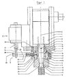
- the extrusion head comprises a housing 1 that forms the axis 2.
- the housing 1 is held by a support element 4.
- a first bore which forms a first inner surface 3.
- a nozzle head 5 is connected by means of a hinge assembly 7.
- a hinge assembly 7 Through the housing 1 and the nozzle head 5 through a sleeve 6 extends between the sleeve 6 and the nozzle head and the first inner surface a ring channel is formed, flows in the extruded plastic material and exits in the form of a molding 8 at the end.
- the nozzle head 5 and the housing 1 are connected to each other via the hinge assembly 7 so that a pivoting adjustment of the nozzle head 5 to the housing 1 is effected via an adjusting mechanism 9.
- the nozzle head 5 has a second bore with a second inner surface 10, which is arranged at a radial distance to the outer surface 11 of the sleeve 6, so that between them a gap 12 is given at the outlet end 13, from which the molded article 8 emerges.
- the second bore follows with the interposition of a bore in the region of the components of the joint arrangement 7 on the first bore in the housing first
- the hinge arrangement 7 comprises a first bearing element 14 with a ring shoulder 15 and at the face facing the nozzle outlet end 13 with an outer spherical surface 16.
- the center of the outer spherical surface 16 lies on the axis 2 and is designated M.
- a holder which comprises a first retaining ring 17 and a second retaining ring 18.
- the first retaining ring 17 engages over the annular shoulder 15 of the first bearing element 14 and is fixed by screws 19 on the support member 4 and a transverse plate thereof.
- the second retaining ring 18 serves to fix a second bearing element 21, which has an inner spherical surface 22.
- This inner ball surface 22 is designed to match the outer spherical surface 16 of the first bearing element 14 and abuts against it.
- the second bearing element 21 has a spherical outer surface 23 which, like the inner spherical surface 22 and the outer spherical surface 16, has the center M.
- On the spherical outer surface 23 is a spherical inner surface 24 of the second retaining ring 18 at.
- the second retaining ring 18 is connected by screws 20 with the first retaining ring 17.
- the nozzle head 5 is fixedly connected to the second bearing element 21 by means of screws.
- the first inner surface 3 and the second inner surface 10 are partially seated in the first bearing element 14 and the second bearing element 21 and together form an annular channel around the outer surface 11 of the sleeve 6, which ends at the nozzle exit end 13, ie in the region of the end face of the nozzle head 5 and sleeve 6 in the form of an annular gap about the axis 2, from this Gap 12 at the nozzle exit end 13 of the molding 8, consisting of the conveyed in the annular channel plastic material exits.
- the hinge assembly 7 is provided which allows pivoting of the nozzle head 5 in relation to the stationary sleeve 6.
- this pivoting due to the spherical configuration of the bearing surfaces, namely the outer spherical surface 16 and inner spherical surface 22 of the two bearing elements 14, 21 done on all sides.
- the adjusting mechanism 9 is provided.
- This adjusting mechanism 9 comprises an adjusting lever 26, which is mounted radially relative to the axis 2, projecting on the second bearing element 21, whereby the adjusting shaft 28 is formed.
- the adjusting lever 26 has at the end of a traverse 29. It is firmly connected by screws 27 with the second bearing element 21.
- linear actuators 33 for example in the form of hydraulic cylinders, which are designed to be double acting on.
- linear actuators 33 There are two linear actuators 33 are provided, which attack with the offset 32 opposite of the adjusting axis 28 on the cross member 29, wherein each linear actuator 33 associated connection eye 34 is fixed via a respective screw 35 to the cross member 29.
- the linear actuators 33 cause a force along the lines of action 31, which are parallel to the axis 2.
- the linear actuators 33 are connected to the support frame 4.
- the lines of action 31 act at an angle 36 relative to the control axis 28, this angle being increased or decreased when actuated.
Landscapes
- Engineering & Computer Science (AREA)
- Mechanical Engineering (AREA)
- Manufacturing & Machinery (AREA)
- Extrusion Moulding Of Plastics Or The Like (AREA)
- Addition Polymer Or Copolymer, Post-Treatments, Or Chemical Modifications (AREA)
Claims (5)
- Filière d'extrudeuse pour la fabrication d'ébauches (8) en forme de tuyau souple à partir d'une matière plastique extrudable comprenant un logement (1),- qui forme un axe (2),- qui présente un premier alésage, qui forme une première surface intérieure (3) et est centré sur l'axe (2),
une tête de filière (5),- qui présente un deuxième alésage, qui forme une deuxième surface intérieure (10), laquelle aboutit à une extrémité de sortie de filière (13),
un fourreau (6),- qui s'étend dans le premier alésage du logement (1) et dans le deuxième alésage de la tête de filière (5) le long de l'axe (2),- qui présente une surface extérieure (11) et aboutit à une extrémité de sortie de filière (13),- dans laquelle entre la deuxième surface intérieure (10) et la surface extérieure (11) une ouverture (12) est formée, à travers laquelle la matière plastique est transportée pour former l'ébauche (8) en forme de tuyau souple, qui ressort de la tête de filière (5) à l'extrémité de sortie de filière (13),
un agencement de joint articulé (7),- qui comprend des surfaces de bille (23, 24) guidées l'une sur l'autre, desquelles une est coordonnée à un premier élément de palier (14) et l'autre est coordonnée à un deuxième élément de palier (21), qui est relié à la tête de filière (5) et- qui relie de manière étanche et basculable de tous les côtés la tête de filière (5) au logement (1),
un mécanisme de manoeuvre (9),- par l'intermédiaire duquel la tête de filière (5) peut être déplacée de manière basculante de tous les côtés et- qui comprend un levier de manoeuvre (26), qui est relié au deuxième élément de palier (21) et forme un axe de manoeuvre (28) s'étendant radialement par rapport à l'axe (2), caractérisé en ce que,
le mécanisme de manoeuvre (9) comprend deux actionneurs linéaires (33), qui viennent en prise avec le levier de manoeuvre (26) le long de lignes d'action de forces (31), qui s'étendent parallèlement à l'axe (2), de sorte que les actionneurs linéaires (33) viennent en prise avec le levier de manoeuvre (26) en formant un angle (36) et en décalage par l'axe de manoeuvre (28) en sens opposé, dans laquelle les actionneurs linéaires (33) sont disposés parallèlement et directement à côté les uns des autres. - Filière d'extrudeuse selon la revendication 1,
caractérisée en ce que,
l'agencement de joint articulé (7)- présente un premier élément de palier (14) annulaire avec une surface de bille extérieure (16) sur un côté frontal,- présente un deuxième élément de palier (21) avec une surface de bille intérieure (22) s'ajustant à la surface de bille extérieure (16), sur laquelle elle est guidée de manière basculable de tous les côtés et est reliée à la tête de filière (5),- présente une console (17, 18),qui maintient le deuxième élément de palier (21) avec sa surface de bille intérieure (22) de sorte qu'il vienne repose sur la surface de bille extérieure (16) du premier élément de palier (14) de manière étanche et basculante de tous les côtés. - Filière d'extrudeuse selon la revendication 2,
caractérisée en ce que,
le deuxième élément de palier (21) présente une surface extérieure (23) sphérique disposée concentriquement par rapport à la surface de bille intérieure (22) et
la console (17, 18) présente une surface intérieure (24) sphérique s'ajustant à la surface extérieure sphérique (23). - Filière d'extrudeuse selon la revendication 2,
caractérisée en ce que
la console (17, 18) est immobilisée sur l'élément porteur (4). - Filière d'extrudeuse selon la revendication 1,
caractérisée en ce que,
les actionneurs linéaires (33) sont réalisés comme des cylindres hydrauliques à double action.
Priority Applications (1)
| Application Number | Priority Date | Filing Date | Title |
|---|---|---|---|
| PL05025941T PL1661687T3 (pl) | 2004-11-30 | 2005-11-29 | Głowica wytłaczająca z nastawianiem szczeliny dyszowej |
Applications Claiming Priority (1)
| Application Number | Priority Date | Filing Date | Title |
|---|---|---|---|
| DE102004057974A DE102004057974B4 (de) | 2004-11-30 | 2004-11-30 | Extrusionskopf mit Düsenspalteinstellung |
Publications (2)
| Publication Number | Publication Date |
|---|---|
| EP1661687A1 EP1661687A1 (fr) | 2006-05-31 |
| EP1661687B1 true EP1661687B1 (fr) | 2011-01-26 |
Family
ID=35777516
Family Applications (1)
| Application Number | Title | Priority Date | Filing Date |
|---|---|---|---|
| EP05025941A Not-in-force EP1661687B1 (fr) | 2004-11-30 | 2005-11-29 | Filière d'extrudeuse avec ajustement de l'ouverture de la filière |
Country Status (5)
| Country | Link |
|---|---|
| EP (1) | EP1661687B1 (fr) |
| AT (1) | ATE496752T1 (fr) |
| DE (1) | DE102004057974B4 (fr) |
| ES (1) | ES2357828T3 (fr) |
| PL (1) | PL1661687T3 (fr) |
Families Citing this family (8)
| Publication number | Priority date | Publication date | Assignee | Title |
|---|---|---|---|---|
| DE102006042065B4 (de) * | 2006-09-05 | 2021-05-12 | Kautex Textron Gmbh & Co. Kg | Verfahren und Vorrichtung zur Herstellung von bandförmigen Kunststoffvorformlingen |
| DE102006062893B3 (de) | 2006-09-05 | 2023-07-13 | Kautex Textron Gmbh & Co. Kg | Vorrichtung zur Herstellung von bandförmigen Kunststoffvorformlingen |
| JP5006400B2 (ja) | 2006-10-05 | 2012-08-22 | イナジー・オートモーティブ・システムズ・リサーチ・(ソシエテ・アノニム) | パリソンからプラスチック中空体を製造するための方法およびパリソン押出し用ダイ |
| DE102009058361B3 (de) | 2009-12-15 | 2011-06-01 | Gross, Heinz, Dr.-Ing. | Düse |
| DE102012022409B3 (de) * | 2012-11-15 | 2013-05-29 | Heinz Gross | Schlauchkopf mit trifunktionellem Bauteil |
| DE102013109495B3 (de) * | 2013-08-30 | 2014-08-14 | Harald Feuerherm | Extrusionswerkzeug zur Erzeugung schlauchförmiger Vorformlinge |
| DE102014103101B4 (de) * | 2014-03-07 | 2018-04-12 | Harald Feuerherm | Verfahren zur Herstellung blasgeformter Kunststoffhohlkörper und Mehrfachextrusionskopf zur Durchführung des Verfahrens |
| CN204033937U (zh) * | 2014-03-17 | 2014-12-24 | 胡绍勤 | 输液用双刻度精准定速定量调节器 |
Family Cites Families (7)
| Publication number | Priority date | Publication date | Assignee | Title |
|---|---|---|---|---|
| SE301378B (fr) * | 1963-08-27 | 1968-06-04 | Kalle Ag | |
| DE3216377A1 (de) * | 1981-09-26 | 1983-06-16 | Detlef Dipl.-Ing. 4970 Bad Oeynhausen Gneuss | Vorrichtung zur herstellung von rohren aus plastischen massen |
| JPS60105520A (ja) * | 1983-11-14 | 1985-06-11 | Hitachi Cable Ltd | 押出機のクロスヘツド用ダイス偏心調整装置 |
| DE3505837C2 (de) * | 1985-02-20 | 1994-06-23 | Battenfeld Extrusionstech | Spritzkopf zur Herstellung von Rohren aus thermoplastischem Kunststoff |
| DE19537132C2 (de) * | 1995-10-05 | 2003-08-07 | Mbk Maschb Koetke Gmbh | Blaskopf mit verstellbarer Düse |
| DE29707060U1 (de) * | 1997-04-21 | 1997-07-10 | Fischer W Mueller Blasformtech | Extrusionskopf für das Blasformen von Hohlkörpern |
| DE102004028100B4 (de) * | 2004-06-09 | 2009-09-17 | Thermo-Technik-Systeme Gmbh | Extrusionsblaskopf |
-
2004
- 2004-11-30 DE DE102004057974A patent/DE102004057974B4/de not_active Expired - Fee Related
-
2005
- 2005-11-29 ES ES05025941T patent/ES2357828T3/es active Active
- 2005-11-29 EP EP05025941A patent/EP1661687B1/fr not_active Not-in-force
- 2005-11-29 AT AT05025941T patent/ATE496752T1/de active
- 2005-11-29 PL PL05025941T patent/PL1661687T3/pl unknown
Also Published As
| Publication number | Publication date |
|---|---|
| DE102004057974B4 (de) | 2009-05-07 |
| DE102004057974A1 (de) | 2006-06-01 |
| ATE496752T1 (de) | 2011-02-15 |
| EP1661687A1 (fr) | 2006-05-31 |
| PL1661687T3 (pl) | 2011-06-30 |
| ES2357828T3 (es) | 2011-05-03 |
Similar Documents
| Publication | Publication Date | Title |
|---|---|---|
| EP1661687B1 (fr) | Filière d'extrudeuse avec ajustement de l'ouverture de la filière | |
| EP0563575B1 (fr) | Procédé et dispositif de production en continu d'un tube composite avec manchon | |
| DE2413879C3 (de) | Vorrichtung zur Herstellung eines doppelwandigen Kunststoffrohrs aus einem gewellten Außenrohr und einem glatten Innenrohr | |
| DE102013109495B3 (de) | Extrusionswerkzeug zur Erzeugung schlauchförmiger Vorformlinge | |
| EP1604801A2 (fr) | Tête de soufflage pour extrusion | |
| DE10145322A1 (de) | Lageranordnung für Zylinder, Walzen oder Trommeln | |
| DE102006042065B4 (de) | Verfahren und Vorrichtung zur Herstellung von bandförmigen Kunststoffvorformlingen | |
| DE202006013751U1 (de) | Vorrichtung zur Herstellung von bandförmigen Kunststoffvorformlingen | |
| DE2735571A1 (de) | Vorrichtung und verfahren zum beschichten von stahlrohr | |
| EP0250828A2 (fr) | Installation d'extrusion pour le revêtement de produits cylindriques, en particulier un câble | |
| EP3124199B1 (fr) | Douille de calibrage reglable en continu pour tuyaux en matiere plastique extrudes | |
| EP2422906B1 (fr) | Support d'outil doté d'un mécanisme d'évitement et son procédé de fabrication | |
| DE19634162C2 (de) | Extrusionsschnecke für einen Extruder | |
| DE2631376B1 (de) | Kreuzkopfzapfenlager fuer Kolbenmaschinen,insbesondere fuer Dieselbrennkraftmaschinen | |
| EP0490362B1 (fr) | Extrudeuse à haut rendement à nombre de filets constant dans la zone d'entrée et dans la zone de sortie d'un élément de cisaillement par transfert | |
| EP2105292B1 (fr) | Dispositif de réglage de galet | |
| DE102012203632A1 (de) | Linearbewegungsvorrichtung mit einem gesonderten Übertragungskörper zur Schmiermittelübertragung auf den beweglichen Ausleger | |
| DE3001705C2 (de) | Zentriervorrichtung für Formwerkzeuge von Strangpressen | |
| DE2410439A1 (de) | Ausrichtmaschine fuer metallprofile | |
| DE19831588A1 (de) | Zuführeinrichtung | |
| EP0924442B1 (fr) | Coussinet et procédé de sa fabrication | |
| DE102012111117A1 (de) | Extrusionswerkzeug zur Erzeugung eines schlauchförmigen Vorformlings aus einer Kunststoffschmelze | |
| DE4005996C2 (de) | Fügeverfahren für einen Walzenkörper | |
| DE2947250A1 (de) | Unmittelbar einem extruder nachgeordnetes walzwerk | |
| DE102010060658A1 (de) | Walzmaschine zum Umformen von metallischen und/oder eisenhaltigen Werkstücken mit geklemmten Drehlagern und Verfahren zum Wechseln der Walzen oder der Walzenwerkzeuge der Walzmschine |
Legal Events
| Date | Code | Title | Description |
|---|---|---|---|
| PUAI | Public reference made under article 153(3) epc to a published international application that has entered the european phase |
Free format text: ORIGINAL CODE: 0009012 |
|
| AK | Designated contracting states |
Kind code of ref document: A1 Designated state(s): AT BE BG CH CY CZ DE DK EE ES FI FR GB GR HU IE IS IT LI LT LU LV MC NL PL PT RO SE SI SK TR |
|
| AX | Request for extension of the european patent |
Extension state: AL BA HR MK YU |
|
| 17P | Request for examination filed |
Effective date: 20060629 |
|
| AKX | Designation fees paid |
Designated state(s): AT BE BG CH CY CZ DE DK EE ES FI FR GB GR HU IE IS IT LI LT LU LV MC NL PL PT RO SE SI SK TR |
|
| 17Q | First examination report despatched |
Effective date: 20080409 |
|
| GRAP | Despatch of communication of intention to grant a patent |
Free format text: ORIGINAL CODE: EPIDOSNIGR1 |
|
| GRAS | Grant fee paid |
Free format text: ORIGINAL CODE: EPIDOSNIGR3 |
|
| RBV | Designated contracting states (corrected) |
Designated state(s): AT BE BG CH CY CZ DK EE ES FI FR GB GR HU IE IS IT LI LT LU LV MC NL PL PT RO SE SI SK TR |
|
| GRAA | (expected) grant |
Free format text: ORIGINAL CODE: 0009210 |
|
| AK | Designated contracting states |
Kind code of ref document: B1 Designated state(s): AT BE BG CH CY CZ DK EE ES FI FR GB GR HU IE IS IT LI LT LU LV MC NL PL PT RO SE SI SK TR |
|
| REG | Reference to a national code |
Ref country code: GB Ref legal event code: FG4D Free format text: NOT ENGLISH |
|
| REG | Reference to a national code |
Ref country code: DE Ref legal event code: 8566 |
|
| REG | Reference to a national code |
Ref country code: CH Ref legal event code: EP |
|
| REG | Reference to a national code |
Ref country code: IE Ref legal event code: FG4D Free format text: LANGUAGE OF EP DOCUMENT: GERMAN |
|
| REG | Reference to a national code |
Ref country code: NL Ref legal event code: T3 |
|
| REG | Reference to a national code |
Ref country code: ES Ref legal event code: FG2A Ref document number: 2357828 Country of ref document: ES Kind code of ref document: T3 Effective date: 20110503 |
|
| LTIE | Lt: invalidation of european patent or patent extension |
Effective date: 20110126 |
|
| REG | Reference to a national code |
Ref country code: PL Ref legal event code: T3 |
|
| PG25 | Lapsed in a contracting state [announced via postgrant information from national office to epo] |
Ref country code: SE Free format text: LAPSE BECAUSE OF FAILURE TO SUBMIT A TRANSLATION OF THE DESCRIPTION OR TO PAY THE FEE WITHIN THE PRESCRIBED TIME-LIMIT Effective date: 20110126 Ref country code: PT Free format text: LAPSE BECAUSE OF FAILURE TO SUBMIT A TRANSLATION OF THE DESCRIPTION OR TO PAY THE FEE WITHIN THE PRESCRIBED TIME-LIMIT Effective date: 20110526 Ref country code: LT Free format text: LAPSE BECAUSE OF FAILURE TO SUBMIT A TRANSLATION OF THE DESCRIPTION OR TO PAY THE FEE WITHIN THE PRESCRIBED TIME-LIMIT Effective date: 20110126 Ref country code: GR Free format text: LAPSE BECAUSE OF FAILURE TO SUBMIT A TRANSLATION OF THE DESCRIPTION OR TO PAY THE FEE WITHIN THE PRESCRIBED TIME-LIMIT Effective date: 20110427 Ref country code: LV Free format text: LAPSE BECAUSE OF FAILURE TO SUBMIT A TRANSLATION OF THE DESCRIPTION OR TO PAY THE FEE WITHIN THE PRESCRIBED TIME-LIMIT Effective date: 20110126 |
|
| PG25 | Lapsed in a contracting state [announced via postgrant information from national office to epo] |
Ref country code: BG Free format text: LAPSE BECAUSE OF FAILURE TO SUBMIT A TRANSLATION OF THE DESCRIPTION OR TO PAY THE FEE WITHIN THE PRESCRIBED TIME-LIMIT Effective date: 20110426 Ref country code: SI Free format text: LAPSE BECAUSE OF FAILURE TO SUBMIT A TRANSLATION OF THE DESCRIPTION OR TO PAY THE FEE WITHIN THE PRESCRIBED TIME-LIMIT Effective date: 20110126 Ref country code: FI Free format text: LAPSE BECAUSE OF FAILURE TO SUBMIT A TRANSLATION OF THE DESCRIPTION OR TO PAY THE FEE WITHIN THE PRESCRIBED TIME-LIMIT Effective date: 20110126 Ref country code: CY Free format text: LAPSE BECAUSE OF FAILURE TO SUBMIT A TRANSLATION OF THE DESCRIPTION OR TO PAY THE FEE WITHIN THE PRESCRIBED TIME-LIMIT Effective date: 20110126 |
|
| PG25 | Lapsed in a contracting state [announced via postgrant information from national office to epo] |
Ref country code: DK Free format text: LAPSE BECAUSE OF FAILURE TO SUBMIT A TRANSLATION OF THE DESCRIPTION OR TO PAY THE FEE WITHIN THE PRESCRIBED TIME-LIMIT Effective date: 20110126 Ref country code: EE Free format text: LAPSE BECAUSE OF FAILURE TO SUBMIT A TRANSLATION OF THE DESCRIPTION OR TO PAY THE FEE WITHIN THE PRESCRIBED TIME-LIMIT Effective date: 20110126 |
|
| PG25 | Lapsed in a contracting state [announced via postgrant information from national office to epo] |
Ref country code: SK Free format text: LAPSE BECAUSE OF FAILURE TO SUBMIT A TRANSLATION OF THE DESCRIPTION OR TO PAY THE FEE WITHIN THE PRESCRIBED TIME-LIMIT Effective date: 20110126 Ref country code: RO Free format text: LAPSE BECAUSE OF FAILURE TO SUBMIT A TRANSLATION OF THE DESCRIPTION OR TO PAY THE FEE WITHIN THE PRESCRIBED TIME-LIMIT Effective date: 20110126 |
|
| PLBE | No opposition filed within time limit |
Free format text: ORIGINAL CODE: 0009261 |
|
| STAA | Information on the status of an ep patent application or granted ep patent |
Free format text: STATUS: NO OPPOSITION FILED WITHIN TIME LIMIT |
|
| 26N | No opposition filed |
Effective date: 20111027 |
|
| PG25 | Lapsed in a contracting state [announced via postgrant information from national office to epo] |
Ref country code: MC Free format text: LAPSE BECAUSE OF NON-PAYMENT OF DUE FEES Effective date: 20111130 |
|
| PG25 | Lapsed in a contracting state [announced via postgrant information from national office to epo] |
Ref country code: LU Free format text: LAPSE BECAUSE OF NON-PAYMENT OF DUE FEES Effective date: 20111129 |
|
| PG25 | Lapsed in a contracting state [announced via postgrant information from national office to epo] |
Ref country code: HU Free format text: LAPSE BECAUSE OF FAILURE TO SUBMIT A TRANSLATION OF THE DESCRIPTION OR TO PAY THE FEE WITHIN THE PRESCRIBED TIME-LIMIT Effective date: 20110126 |
|
| PGFP | Annual fee paid to national office [announced via postgrant information from national office to epo] |
Ref country code: IE Payment date: 20131121 Year of fee payment: 9 Ref country code: IS Payment date: 20131122 Year of fee payment: 9 |
|
| PGFP | Annual fee paid to national office [announced via postgrant information from national office to epo] |
Ref country code: PL Payment date: 20131120 Year of fee payment: 9 |
|
| REG | Reference to a national code |
Ref country code: IE Ref legal event code: MM4A |
|
| PG25 | Lapsed in a contracting state [announced via postgrant information from national office to epo] |
Ref country code: IS Free format text: LAPSE BECAUSE OF FAILURE TO SUBMIT A TRANSLATION OF THE DESCRIPTION OR TO PAY THE FEE WITHIN THE PRESCRIBED TIME-LIMIT Effective date: 20150531 |
|
| PG25 | Lapsed in a contracting state [announced via postgrant information from national office to epo] |
Ref country code: IE Free format text: LAPSE BECAUSE OF NON-PAYMENT OF DUE FEES Effective date: 20141129 |
|
| REG | Reference to a national code |
Ref country code: FR Ref legal event code: PLFP Year of fee payment: 11 |
|
| PG25 | Lapsed in a contracting state [announced via postgrant information from national office to epo] |
Ref country code: PL Free format text: LAPSE BECAUSE OF NON-PAYMENT OF DUE FEES Effective date: 20141129 |
|
| REG | Reference to a national code |
Ref country code: FR Ref legal event code: PLFP Year of fee payment: 12 |
|
| PGFP | Annual fee paid to national office [announced via postgrant information from national office to epo] |
Ref country code: TR Payment date: 20161122 Year of fee payment: 12 |
|
| REG | Reference to a national code |
Ref country code: FR Ref legal event code: PLFP Year of fee payment: 13 |
|
| PGFP | Annual fee paid to national office [announced via postgrant information from national office to epo] |
Ref country code: FR Payment date: 20211119 Year of fee payment: 17 Ref country code: ES Payment date: 20211216 Year of fee payment: 17 Ref country code: NL Payment date: 20211119 Year of fee payment: 17 Ref country code: GB Payment date: 20211123 Year of fee payment: 17 Ref country code: AT Payment date: 20211117 Year of fee payment: 17 Ref country code: CZ Payment date: 20211118 Year of fee payment: 17 |
|
| PGFP | Annual fee paid to national office [announced via postgrant information from national office to epo] |
Ref country code: IT Payment date: 20211130 Year of fee payment: 17 Ref country code: CH Payment date: 20211123 Year of fee payment: 17 Ref country code: BE Payment date: 20211119 Year of fee payment: 17 |
|
| PG25 | Lapsed in a contracting state [announced via postgrant information from national office to epo] |
Ref country code: TR Free format text: LAPSE BECAUSE OF NON-PAYMENT OF DUE FEES Effective date: 20171129 |
|
| REG | Reference to a national code |
Ref country code: CH Ref legal event code: PL |
|
| REG | Reference to a national code |
Ref country code: NL Ref legal event code: MM Effective date: 20221201 |
|
| REG | Reference to a national code |
Ref country code: AT Ref legal event code: MM01 Ref document number: 496752 Country of ref document: AT Kind code of ref document: T Effective date: 20221129 |
|
| GBPC | Gb: european patent ceased through non-payment of renewal fee |
Effective date: 20221129 |
|
| REG | Reference to a national code |
Ref country code: BE Ref legal event code: MM Effective date: 20221130 |
|
| PG25 | Lapsed in a contracting state [announced via postgrant information from national office to epo] |
Ref country code: LI Free format text: LAPSE BECAUSE OF NON-PAYMENT OF DUE FEES Effective date: 20221130 Ref country code: CZ Free format text: LAPSE BECAUSE OF NON-PAYMENT OF DUE FEES Effective date: 20221129 Ref country code: CH Free format text: LAPSE BECAUSE OF NON-PAYMENT OF DUE FEES Effective date: 20221130 Ref country code: AT Free format text: LAPSE BECAUSE OF NON-PAYMENT OF DUE FEES Effective date: 20221129 |
|
| PG25 | Lapsed in a contracting state [announced via postgrant information from national office to epo] |
Ref country code: NL Free format text: LAPSE BECAUSE OF NON-PAYMENT OF DUE FEES Effective date: 20221201 |
|
| PG25 | Lapsed in a contracting state [announced via postgrant information from national office to epo] |
Ref country code: IT Free format text: LAPSE BECAUSE OF NON-PAYMENT OF DUE FEES Effective date: 20221129 Ref country code: GB Free format text: LAPSE BECAUSE OF NON-PAYMENT OF DUE FEES Effective date: 20221129 |
|
| PG25 | Lapsed in a contracting state [announced via postgrant information from national office to epo] |
Ref country code: FR Free format text: LAPSE BECAUSE OF NON-PAYMENT OF DUE FEES Effective date: 20221130 Ref country code: BE Free format text: LAPSE BECAUSE OF NON-PAYMENT OF DUE FEES Effective date: 20221130 |
|
| REG | Reference to a national code |
Ref country code: ES Ref legal event code: FD2A Effective date: 20240102 |
|
| PG25 | Lapsed in a contracting state [announced via postgrant information from national office to epo] |
Ref country code: ES Free format text: LAPSE BECAUSE OF NON-PAYMENT OF DUE FEES Effective date: 20221130 |
|
| PG25 | Lapsed in a contracting state [announced via postgrant information from national office to epo] |
Ref country code: ES Free format text: LAPSE BECAUSE OF NON-PAYMENT OF DUE FEES Effective date: 20221130 |