EP1661687B1 - Extrusion die with die opening adjustment - Google Patents
Extrusion die with die opening adjustment Download PDFInfo
- Publication number
- EP1661687B1 EP1661687B1 EP05025941A EP05025941A EP1661687B1 EP 1661687 B1 EP1661687 B1 EP 1661687B1 EP 05025941 A EP05025941 A EP 05025941A EP 05025941 A EP05025941 A EP 05025941A EP 1661687 B1 EP1661687 B1 EP 1661687B1
- Authority
- EP
- European Patent Office
- Prior art keywords
- axis
- spherical
- bearing element
- face
- die head
- Prior art date
- Legal status (The legal status is an assumption and is not a legal conclusion. Google has not performed a legal analysis and makes no representation as to the accuracy of the status listed.)
- Not-in-force
Links
- 238000001125 extrusion Methods 0.000 title claims description 27
- 230000007246 mechanism Effects 0.000 claims abstract description 14
- 239000000463 material Substances 0.000 claims description 13
- 239000004033 plastic Substances 0.000 claims description 12
- 238000000465 moulding Methods 0.000 claims description 8
- 230000009471 action Effects 0.000 claims description 6
- 238000004519 manufacturing process Methods 0.000 claims description 3
- 230000000717 retained effect Effects 0.000 claims 1
- 239000003000 extruded plastic Substances 0.000 abstract description 2
- 230000013011 mating Effects 0.000 abstract 1
- 230000002349 favourable effect Effects 0.000 description 3
- 230000009467 reduction Effects 0.000 description 3
- 230000008719 thickening Effects 0.000 description 3
- 230000008901 benefit Effects 0.000 description 2
- 230000008859 change Effects 0.000 description 2
- 230000002411 adverse Effects 0.000 description 1
- 238000013459 approach Methods 0.000 description 1
- 230000005540 biological transmission Effects 0.000 description 1
- 230000006835 compression Effects 0.000 description 1
- 238000007906 compression Methods 0.000 description 1
- 238000010276 construction Methods 0.000 description 1
- 230000003247 decreasing effect Effects 0.000 description 1
- 230000000694 effects Effects 0.000 description 1
Images

Classifications
-
- B—PERFORMING OPERATIONS; TRANSPORTING
- B29—WORKING OF PLASTICS; WORKING OF SUBSTANCES IN A PLASTIC STATE IN GENERAL
- B29C—SHAPING OR JOINING OF PLASTICS; SHAPING OF MATERIAL IN A PLASTIC STATE, NOT OTHERWISE PROVIDED FOR; AFTER-TREATMENT OF THE SHAPED PRODUCTS, e.g. REPAIRING
- B29C48/00—Extrusion moulding, i.e. expressing the moulding material through a die or nozzle which imparts the desired form; Apparatus therefor
- B29C48/25—Component parts, details or accessories; Auxiliary operations
- B29C48/30—Extrusion nozzles or dies
- B29C48/32—Extrusion nozzles or dies with annular openings, e.g. for forming tubular articles
- B29C48/325—Extrusion nozzles or dies with annular openings, e.g. for forming tubular articles being adjustable, i.e. having adjustable exit sections
- B29C48/327—Extrusion nozzles or dies with annular openings, e.g. for forming tubular articles being adjustable, i.e. having adjustable exit sections with centering means
-
- B—PERFORMING OPERATIONS; TRANSPORTING
- B29—WORKING OF PLASTICS; WORKING OF SUBSTANCES IN A PLASTIC STATE IN GENERAL
- B29C—SHAPING OR JOINING OF PLASTICS; SHAPING OF MATERIAL IN A PLASTIC STATE, NOT OTHERWISE PROVIDED FOR; AFTER-TREATMENT OF THE SHAPED PRODUCTS, e.g. REPAIRING
- B29C48/00—Extrusion moulding, i.e. expressing the moulding material through a die or nozzle which imparts the desired form; Apparatus therefor
- B29C48/03—Extrusion moulding, i.e. expressing the moulding material through a die or nozzle which imparts the desired form; Apparatus therefor characterised by the shape of the extruded material at extrusion
- B29C48/09—Articles with cross-sections having partially or fully enclosed cavities, e.g. pipes or channels
-
- B—PERFORMING OPERATIONS; TRANSPORTING
- B29—WORKING OF PLASTICS; WORKING OF SUBSTANCES IN A PLASTIC STATE IN GENERAL
- B29C—SHAPING OR JOINING OF PLASTICS; SHAPING OF MATERIAL IN A PLASTIC STATE, NOT OTHERWISE PROVIDED FOR; AFTER-TREATMENT OF THE SHAPED PRODUCTS, e.g. REPAIRING
- B29C48/00—Extrusion moulding, i.e. expressing the moulding material through a die or nozzle which imparts the desired form; Apparatus therefor
- B29C48/25—Component parts, details or accessories; Auxiliary operations
- B29C48/252—Drive or actuation means; Transmission means; Screw supporting means
- B29C48/2528—Drive or actuation means for non-plasticising purposes, e.g. dosing unit
-
- B—PERFORMING OPERATIONS; TRANSPORTING
- B29—WORKING OF PLASTICS; WORKING OF SUBSTANCES IN A PLASTIC STATE IN GENERAL
- B29C—SHAPING OR JOINING OF PLASTICS; SHAPING OF MATERIAL IN A PLASTIC STATE, NOT OTHERWISE PROVIDED FOR; AFTER-TREATMENT OF THE SHAPED PRODUCTS, e.g. REPAIRING
- B29C48/00—Extrusion moulding, i.e. expressing the moulding material through a die or nozzle which imparts the desired form; Apparatus therefor
- B29C48/25—Component parts, details or accessories; Auxiliary operations
- B29C48/30—Extrusion nozzles or dies
- B29C48/32—Extrusion nozzles or dies with annular openings, e.g. for forming tubular articles
- B29C48/325—Extrusion nozzles or dies with annular openings, e.g. for forming tubular articles being adjustable, i.e. having adjustable exit sections
-
- B—PERFORMING OPERATIONS; TRANSPORTING
- B29—WORKING OF PLASTICS; WORKING OF SUBSTANCES IN A PLASTIC STATE IN GENERAL
- B29C—SHAPING OR JOINING OF PLASTICS; SHAPING OF MATERIAL IN A PLASTIC STATE, NOT OTHERWISE PROVIDED FOR; AFTER-TREATMENT OF THE SHAPED PRODUCTS, e.g. REPAIRING
- B29C48/00—Extrusion moulding, i.e. expressing the moulding material through a die or nozzle which imparts the desired form; Apparatus therefor
- B29C48/25—Component parts, details or accessories; Auxiliary operations
- B29C48/92—Measuring, controlling or regulating
-
- B—PERFORMING OPERATIONS; TRANSPORTING
- B29—WORKING OF PLASTICS; WORKING OF SUBSTANCES IN A PLASTIC STATE IN GENERAL
- B29C—SHAPING OR JOINING OF PLASTICS; SHAPING OF MATERIAL IN A PLASTIC STATE, NOT OTHERWISE PROVIDED FOR; AFTER-TREATMENT OF THE SHAPED PRODUCTS, e.g. REPAIRING
- B29C2948/00—Indexing scheme relating to extrusion moulding
- B29C2948/92—Measuring, controlling or regulating
- B29C2948/92504—Controlled parameter
- B29C2948/92609—Dimensions
- B29C2948/92647—Thickness
-
- B—PERFORMING OPERATIONS; TRANSPORTING
- B29—WORKING OF PLASTICS; WORKING OF SUBSTANCES IN A PLASTIC STATE IN GENERAL
- B29C—SHAPING OR JOINING OF PLASTICS; SHAPING OF MATERIAL IN A PLASTIC STATE, NOT OTHERWISE PROVIDED FOR; AFTER-TREATMENT OF THE SHAPED PRODUCTS, e.g. REPAIRING
- B29C2948/00—Indexing scheme relating to extrusion moulding
- B29C2948/92—Measuring, controlling or regulating
- B29C2948/92504—Controlled parameter
- B29C2948/92609—Dimensions
- B29C2948/92666—Distortion, shrinkage, dilatation, swell or warpage
-
- B—PERFORMING OPERATIONS; TRANSPORTING
- B29—WORKING OF PLASTICS; WORKING OF SUBSTANCES IN A PLASTIC STATE IN GENERAL
- B29C—SHAPING OR JOINING OF PLASTICS; SHAPING OF MATERIAL IN A PLASTIC STATE, NOT OTHERWISE PROVIDED FOR; AFTER-TREATMENT OF THE SHAPED PRODUCTS, e.g. REPAIRING
- B29C49/00—Blow-moulding, i.e. blowing a preform or parison to a desired shape within a mould; Apparatus therefor
- B29C49/02—Combined blow-moulding and manufacture of the preform or the parison
- B29C49/04—Extrusion blow-moulding
- B29C49/04108—Extrusion blow-moulding extruding several parisons parallel to each other at the same time
Definitions
- Such an extrusion head is from the JP 60-105520 known.
- US 4,472,129 shows an extrusion head, in which a nozzle head is articulated via spherical surfaces. To the nozzle head engage two adjusting rods, which are arranged relative to a central axis of the extrusion head diametrically to each other and parallel to the central axis. The adjusting rods extend in bores of the extrusion head and protrude on an upper side of the same and are driven axially displaceable there via actuating cylinder.
- the DE 35 05 83 7 A1 discloses an extrusion head for making tubular molded articles of extrudable plastic material. It comprises a housing which forms an axis. The housing has a first bore that forms a first inner surface and is centered on the axle. The extrusion head further includes a nozzle head having a second bore defining a second inner surface terminating at a nozzle exit end. Furthermore, the extrusion head comprises a sleeve which extends in the first bore of the housing and in the second bore of the nozzle head along the axis. The quill has an outer surface and ends at the nozzle exit end.
- a gap is formed through which the plastic material is conveyed to form the tubular shaped article, wherein the tubular shaped article emerges from the nozzle head at the nozzle exit end.
- the extrusion head still belongs a joint arrangement comprising mutually guided spherical surfaces.
- the first spherical surface is assigned to a first bearing element and the second to a second bearing element.
- the second bearing element is connected to the nozzle head.
- the second bearing element is held with its spherical surface in contact with the spherical surface of the first bearing element via a spring arrangement. It is provided a location mechanism over which the nozzle head is pivotally adjustable on all sides.
- This actuating mechanism provides a servo motor whose drive axis is parallel to the axis of the extrusion head runs.
- the motor is used to drive an eccentric shaft with the interposition of a reduction gear.
- an eccentrically arranged to the drive shaft pin is mounted, which carries a roller. This role is supported on the outer circumference of the extended second bearing element.
- Four such drives are arranged distributed on the circumference of the second bearing element, so that an all-round pivot adjustment can take place.
- the EP 0 873 845 B1 describes an extrusion head for the production of tubular shaped articles made of extrudable plastic material.
- the extrusion head comprises a housing forming a first axis on which a first bore forming a first inner surface is centered. It further includes a nozzle head having a second bore forming a second inner surface which adjoins the first bore along the axis with the first inner surface and terminates at a nozzle exit end.
- a quill extends along the axis.
- This quill has an outer surface and ends at the nozzle exit end. Between the second inner surface of the nozzle head and the outer surface of the quill is formed a gap through which plastic material is conveyed to form the tubular shaped article. The molding emerges from the nozzle head at the nozzle end.
- the nozzle head is associated with an actuating mechanism which comprises two radially extending from the nozzle head, based on the axis, actuators. These two actuators are arranged at an angle of 90 ° circumferentially offset from one another.
- the one actuator acts directly on the nozzle head and is used for adjustment in a first axial direction.
- the second actuator acts through the intermediary of an adjusting ring on the nozzle head such that an adjustment of the same in a direction which is perpendicular to the first direction of adjustment, is possible. This is intended to be cross slide-type construction for the adjustment can be achieved.
- the nozzle head is thereby adjustable with its inner surface to the associated inner surface of the first bore of the housing in a radial planes in two axes, ie also at the nozzle exit end an adjustment takes place parallel to this radial plane.
- the invention has for its object to provide an extrusion head, which allows an adjustment for adjusting the gap over the circumference, the influence on the flow behavior of the plastic material is low and moreover several extrusion heads can be arranged side by side in the smallest possible space.
- the actuating mechanism comprises two linear actuators which act along force lines on the actuating lever, which run parallel to the axis, so that the linear actuators offset from the adjusting axis and attack at an angle on the lever, the linear actuators parallel and immediate are arranged side by side, according to the characterizing part of Anpruchs first
- An advantage of this design is that the all-round pivoting arrangement of the nozzle head to the housing overall allows a favorable arrangement of the actuating mechanism, because the actuators, if they are designed as linear drives can be arranged so that the transmission in one direction parallel to an axis the sleeve or the first hole in the housing takes place.
- these drives which are one-sided Allow pivoting, be arranged directly next to each other in parallel, so that they can be arranged offset away from the axis to one side and thereby with its force line of action parallel to the axis.
- the seal is ensured by the adjacent spherical surfaces.
- the center of the outer spherical surface and the inner spherical surface is arranged offset on the axis of the nozzle exit end and the outer spherical surfaces or inner spherical surface away. It is the through the outer spherical surface and the inner spherical surface formed radius smaller than the radius by which the nozzle exit end pivots.
- the second bearing element has a concentric with the inner spherical surface arranged spherical outer surface and in that the holder has a spherical inner surface matching the spherical outer surface.
- the holder is fixed to the support element.
- the two linear actuators are designed as double-acting hydraulic cylinders. These may for example be connected to the adjusting lever via a ball eye, so that no constraints occur. But there are also other power-operated or manually operable linear actuators used.
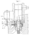
- the extrusion head comprises a housing 1 that forms the axis 2.
- the housing 1 is held by a support element 4.
- a first bore which forms a first inner surface 3.
- a nozzle head 5 is connected by means of a hinge assembly 7.
- a hinge assembly 7 Through the housing 1 and the nozzle head 5 through a sleeve 6 extends between the sleeve 6 and the nozzle head and the first inner surface a ring channel is formed, flows in the extruded plastic material and exits in the form of a molding 8 at the end.
- the nozzle head 5 and the housing 1 are connected to each other via the hinge assembly 7 so that a pivoting adjustment of the nozzle head 5 to the housing 1 is effected via an adjusting mechanism 9.
- the nozzle head 5 has a second bore with a second inner surface 10, which is arranged at a radial distance to the outer surface 11 of the sleeve 6, so that between them a gap 12 is given at the outlet end 13, from which the molded article 8 emerges.
- the second bore follows with the interposition of a bore in the region of the components of the joint arrangement 7 on the first bore in the housing first
- the hinge arrangement 7 comprises a first bearing element 14 with a ring shoulder 15 and at the face facing the nozzle outlet end 13 with an outer spherical surface 16.
- the center of the outer spherical surface 16 lies on the axis 2 and is designated M.
- a holder which comprises a first retaining ring 17 and a second retaining ring 18.
- the first retaining ring 17 engages over the annular shoulder 15 of the first bearing element 14 and is fixed by screws 19 on the support member 4 and a transverse plate thereof.
- the second retaining ring 18 serves to fix a second bearing element 21, which has an inner spherical surface 22.
- This inner ball surface 22 is designed to match the outer spherical surface 16 of the first bearing element 14 and abuts against it.
- the second bearing element 21 has a spherical outer surface 23 which, like the inner spherical surface 22 and the outer spherical surface 16, has the center M.
- On the spherical outer surface 23 is a spherical inner surface 24 of the second retaining ring 18 at.
- the second retaining ring 18 is connected by screws 20 with the first retaining ring 17.
- the nozzle head 5 is fixedly connected to the second bearing element 21 by means of screws.
- the first inner surface 3 and the second inner surface 10 are partially seated in the first bearing element 14 and the second bearing element 21 and together form an annular channel around the outer surface 11 of the sleeve 6, which ends at the nozzle exit end 13, ie in the region of the end face of the nozzle head 5 and sleeve 6 in the form of an annular gap about the axis 2, from this Gap 12 at the nozzle exit end 13 of the molding 8, consisting of the conveyed in the annular channel plastic material exits.
- the hinge assembly 7 is provided which allows pivoting of the nozzle head 5 in relation to the stationary sleeve 6.
- this pivoting due to the spherical configuration of the bearing surfaces, namely the outer spherical surface 16 and inner spherical surface 22 of the two bearing elements 14, 21 done on all sides.
- the adjusting mechanism 9 is provided.
- This adjusting mechanism 9 comprises an adjusting lever 26, which is mounted radially relative to the axis 2, projecting on the second bearing element 21, whereby the adjusting shaft 28 is formed.
- the adjusting lever 26 has at the end of a traverse 29. It is firmly connected by screws 27 with the second bearing element 21.
- linear actuators 33 for example in the form of hydraulic cylinders, which are designed to be double acting on.
- linear actuators 33 There are two linear actuators 33 are provided, which attack with the offset 32 opposite of the adjusting axis 28 on the cross member 29, wherein each linear actuator 33 associated connection eye 34 is fixed via a respective screw 35 to the cross member 29.
- the linear actuators 33 cause a force along the lines of action 31, which are parallel to the axis 2.
- the linear actuators 33 are connected to the support frame 4.
- the lines of action 31 act at an angle 36 relative to the control axis 28, this angle being increased or decreased when actuated.
Abstract
Description
Die Erfindung betrifft einen Extrusionskopf zur Herstellung von schlauchförmigen Formlingen aus extrudierbarem Kunststoffmaterial umfassend ein Gehäuse,
- das eine Achse bildet,
- das eine erste Bohrung aufweist, die eine erste Innenfläche bildet und auf der Achse zentriert ist,
einen Düsenkopf , - der eine zweite Bohrung aufweist, die eine zweite Innenfläche bildet, welche an einem Düsenaustrittsende endet,
eine Pinole, - die sich in der ersten Bohrung des Gehäuses und in der zweiten Bohrung des Düsenkopfes entlang der Achse erstreckt,
- die eine Außenfläche aufweist und am Düsenaustrittsende endet,
- wobei zwischen der zweiten Innenfläche und der Außenfläche ein Spalt gebildet ist, durch den das Kunststoffmaterial zur Bildung des schlauchförmigen Formlings gefördert wird, welcher am Düsen-austrittsende aus dem Düsenkopf austritt,
eine Gelenkanordnung, - die aneinander geführte Kugelflächen, von denen eine einem ersten Lagerelement und die andere einem zweiten Lagerelement zugeordnet ist, welches mit dem Düsenkopf verbunden ist, umfasst und
- die den Düsenkopf mit dem Gehäuse allseitig schwenkbar und dicht verbindet,
und
einen Stellmechanismus, - über den der Düsenkopf allseitig schwenkend verstellbar ist und
- der einen Stellhebel umfasst, der mit einem der Lagerelemente verbunden ist und eine bezüglich der Achse radial verlaufende Stellachse bildet, gemäβ den oberbegriff des
Anpruchs 1.
- that forms an axis,
- having a first bore forming a first inner surface and centered on the axis,
a nozzle head, - having a second bore forming a second inner surface terminating at a nozzle exit end,
a quill, - which extends in the first bore of the housing and in the second bore of the nozzle head along the axis,
- which has an outer surface and ends at the nozzle exit end,
- wherein a gap is formed between the second inner surface and the outer surface through which the plastic material is conveyed to form the tubular shaped article which emerges from the nozzle head at the nozzle outlet end,
a joint arrangement, - the mutually guided spherical surfaces, one of which is associated with a first bearing element and the other a second bearing element, which is connected to the nozzle head comprises, and
- which connects the nozzle head with the housing on all sides pivoting and tight,
and
an actuating mechanism, - over which the nozzle head is pivotable on all sides and
- which comprises an adjusting lever which is connected to one of the bearing elements and forms a control axis extending radially with respect to the axis, according to the preamble of
claim 1.
Ein solcher Extrusionskopf ist aus der
Die
Das zweite Lagerelement ist mit dem Düsenkopf verbunden. Das zweite Lagerelement wird mit seiner Kugelfläche in Anlage zur Kugelfläche des ersten Lagerelementes über eine Federanordnung gehalten. Es ist ein Stellenmechanismus vorgesehen, über den der Düsenkopf allseitig schwenkend verstellbar ist. Dieser Stellmechanismus sieht einen Stellmotor vor, dessen Antriebsachse parallel zur Achse des Extrusionskopfes verläuft. Der Motor dient zum Antrieb einer Exzenterwelle unter Zwischenschaltung eines Untersetzungsgetriebes. Am Ende dieser Welle ist ein exzentrisch zur Antriebsachse angeordneter Zapfen angebracht, der eine Rolle trägt. Diese Rolle stützt sich am Außenumfang des verlängerten zweiten Lagerelementes ab. Vier solcher Antriebe sind auf dem Umfang des zweiten Lagerelementes verteilt angeordnet, so dass eine allseitige Schwenkverstellung erfolgen kann.The second bearing element is connected to the nozzle head. The second bearing element is held with its spherical surface in contact with the spherical surface of the first bearing element via a spring arrangement. It is provided a location mechanism over which the nozzle head is pivotally adjustable on all sides. This actuating mechanism provides a servo motor whose drive axis is parallel to the axis of the extrusion head runs. The motor is used to drive an eccentric shaft with the interposition of a reduction gear. At the end of this shaft, an eccentrically arranged to the drive shaft pin is mounted, which carries a roller. This role is supported on the outer circumference of the extended second bearing element. Four such drives are arranged distributed on the circumference of the second bearing element, so that an all-round pivot adjustment can take place.
Bei einer Schwenkverstellung, die vier auf dem Umfang verteilte Antriebe benötigt, ist der erforderlich Bauraum groß, so dass eine dichte Anordnung von Extrusionsköpfen in paralleler Anordnung nebeneinander nicht möglich ist. Darüber hinaus ist der Aufwand auch insofern groß, als insgesamt vier Antriebe erforderlich sind.In a pivot adjustment, which requires four distributed on the circumference drives, the required space is large, so that a dense arrangement of extrusion heads in parallel arrangement next to each other is not possible. In addition, the effort is so great, as a total of four drives are required.
Die
Durch die erste und die zweite Bohrung hindurch erstreckt sich eine Pinole entlang der Achse. Diese Pinole weist eine Außenfläche auf und endet am Düsenaustrittsende. Zwischen der zweiten Innenfläche des Düsenkopfes und der Außenfläche der Pinole ist ein Spalt gebildet, durch den Kunststoffmaterial zur Bildung des schlauchförmigen Formlings gefördert wird. Der Formling tritt am Düsenende aus dem Düsenkopf aus.Through the first and the second bore, a quill extends along the axis. This quill has an outer surface and ends at the nozzle exit end. Between the second inner surface of the nozzle head and the outer surface of the quill is formed a gap through which plastic material is conveyed to form the tubular shaped article. The molding emerges from the nozzle head at the nozzle end.
Dem Düsenkopf ist ein Stellmechanismus zugeordnet, der zwei radial vom Düsenkopf, bezogen auf die Achse, abstehende Stellantriebe umfasst. Diese beiden Stellantriebe sind in einem Winkel von 90° umfangsversetzt zueinander angeordnet. Der eine Stellantrieb wirkt unmittelbar auf den Düsenkopf ein und dient zur Verstellung in einer ersten Achsrichtung. Der zweite Stellantrieb wirkt unter Vermittlung eines Stellringes auf den Düsenkopf derart ein, dass eine Verstellung desselben in einer Richtung, die senkrecht zur ersten Stellrichtung steht, möglich ist. Hierdurch soll ein kreuzschlittenartiger Aufbau für die Verstellung erzielt werden. Der Düsenkopf wird dadurch mit seiner Innenfläche zu der zugehörigen Innenfläche der ersten Bohrung des Gehäuses in einer radialen Ebenen in zwei Achsen verstellbar, d.h. auch am Düsenaustrittsende erfolgt eine Verstellung parallel zu dieser Radialebene. Hierdurch entstehen Bereiche, in denen die zweite Innenfläche des Düsenkopfes über die erste Innenfläche der ersten Bohrung in den Spalt hinein vortritt bzw. aus diesem zurücktritt. Hierdurch erfolgt eine Störung des Flusses des Kunststoffmateriales im Spalt. Es erfordert die Anordnung der Stellantriebe in Radialebenen um 90° zueinander versetzt einen erheblichen Freiraum, was sich bezüglich des Stichmaßes mit dem mehrere solcher Extrusionsköpfe parallel nebeneinander angeordnet sind, negativ auswirkt. Das bedeutet, dass auf eine vorgegebene Länge nur eine geringere Anzahl von Extrusionsköpfen angeordnet werden kann, weil diese einen Mindestabstand zueinander aufweisen müssen.The nozzle head is associated with an actuating mechanism which comprises two radially extending from the nozzle head, based on the axis, actuators. These two actuators are arranged at an angle of 90 ° circumferentially offset from one another. The one actuator acts directly on the nozzle head and is used for adjustment in a first axial direction. The second actuator acts through the intermediary of an adjusting ring on the nozzle head such that an adjustment of the same in a direction which is perpendicular to the first direction of adjustment, is possible. This is intended to be cross slide-type construction for the adjustment can be achieved. The nozzle head is thereby adjustable with its inner surface to the associated inner surface of the first bore of the housing in a radial planes in two axes, ie also at the nozzle exit end an adjustment takes place parallel to this radial plane. This results in areas in which the second inner surface of the nozzle head over the first inner surface of the first bore into the gap in or recedes from this. This results in a disturbance of the flow of the plastic material in the gap. It requires the arrangement of the actuators in radial planes offset by 90 ° to each other a considerable amount of space, which are arranged parallel to each other with respect to the gauge with the plurality of such extrusion heads, has a negative effect. This means that only a smaller number of extrusion heads can be arranged to a predetermined length, because they must have a minimum distance from each other.
Der Erfindung liegt die Aufgabe zugrunde einen Extrusionskopf zu schaffen, der eine Verstellung zur Einstellung des Spaltes über den Umfang erlaubt, wobei der Einfluss auf das Fließverhalten des Kunststoffmaterials gering ist und darüber hinaus mehrere Extrusionsköpfe auf möglichst kleinem Raum nebeneinander angeordnet werden können.The invention has for its object to provide an extrusion head, which allows an adjustment for adjusting the gap over the circumference, the influence on the flow behavior of the plastic material is low and moreover several extrusion heads can be arranged side by side in the smallest possible space.
Gelöst wird diese Aufgabe erfindungsgemäß dadurch, dass der Stellmechanismus zwei Linearstellantriebe umfasst, die entlang Kraftwirkungslinien am Stellhebel angreifen, welche parallel zur Achse verlaufen, so dass die Linearstellantriebe entgegengesetzt von der Stellachse versetzt und unter einem Winkel am Stellhebel angreifen, wobei die Linearstellantriebe parallel und unmittelbar nebeneinander angeordnet sind, gemäß dem kennzeichnenden Teil des Anpruchs 1.This object is achieved according to the invention in that the actuating mechanism comprises two linear actuators which act along force lines on the actuating lever, which run parallel to the axis, so that the linear actuators offset from the adjusting axis and attack at an angle on the lever, the linear actuators parallel and immediate are arranged side by side, according to the characterizing part of Anpruchs first
Von Vorteil bei dieser Ausbildung ist, dass die allseitig schwenkbare Anordnung des Düsenkopfes zum Gehäuse insgesamt eine günstige Anordnung des Stellmechanismus erlaubt, weil die Stellantriebe, wenn sie als Linearantriebe gestaltet sind, so angeordnet werden können, dass die Kraftübertragung in einer Richtung parallel zu einer Achse der Pinole bzw. der ersten Bohrung im Gehäuse erfolgt. Darüber hinaus können, weil zwei Antriebe vorgesehen sind, diese Antriebe, die eine allseitige Schwenkung erlauben, unmittelbar nebeneinander parallel angeordnet sein, so dass sie von der Achse weg zu einer Seite hin versetzt angeordnet sein können und dabei mit ihrer Kraftwirkungslinie parallel zur Achse. Dadurch wird Freiraum in der Radialebene geschaffen und zwar zumindest so, dass dann, wenn mehrere Extrusionsköpfe vorzusehen sind, diese weitestgehend dicht aneinander angrenzend angeordnet sein können. Ein weiterer Vorteil besteht darin, dass aufgrund der Anordnung der Kugelflächen entlang der Achse entfernt vom Düsenaustrittsende der Verschwenkungsweg am Düsenaustrittsende für die Spalteinstellung größer ist als im Bereich der aufeinanderliegenden Flächen der Gelenkanordnung in Form der Kugelflächen, so dass praktisch keine Toträume entstehen, die das Fließverhalten des Kunststoffmaterials im Spalt zwischen Pinole und Innenfläche negativ beeinflussen. Vorzugweise ist zwischen der Stellachse des Stellhebels und der Wirklinie des Linearstellantriebes ein Winkel von etwa 90° vorgesehen. Obwohl zwei Linearstellantriebe parallel unmittelbar nebeneinander vorgesehen sind, ist durch die Anordnung eine allseitige Schwenkverstellung möglich.An advantage of this design is that the all-round pivoting arrangement of the nozzle head to the housing overall allows a favorable arrangement of the actuating mechanism, because the actuators, if they are designed as linear drives can be arranged so that the transmission in one direction parallel to an axis the sleeve or the first hole in the housing takes place. In addition, because two drives are provided, these drives, which are one-sided Allow pivoting, be arranged directly next to each other in parallel, so that they can be arranged offset away from the axis to one side and thereby with its force line of action parallel to the axis. As a result, clearance is created in the radial plane and that at least so that when a plurality of extrusion heads are to be provided, they can be arranged as closely as possible adjacent to each other. Another advantage is that due to the arrangement of the spherical surfaces along the axis away from the nozzle exit end of the Verschwenkungsweg at the nozzle exit end for the gap setting is greater than in the area of the superimposed surfaces of the hinge assembly in the form of spherical surfaces, so that virtually no dead spaces arise that the flow behavior of the plastic material in the gap between quill and inner surface adversely affect. Preferably, an angle of about 90 ° is provided between the adjusting axis of the actuating lever and the line of action of the linear actuator. Although two linear actuators are provided in parallel immediately next to each other, an all-round pivot adjustment is possible by the arrangement.
In Ausgestaltung der Erfindung ist vorgesehen, dass die Gelenkanordnung
- ein ringförmiges erstes Lagerelement mit einer Atißenkugelfläche an einer Stirnseite aufweist,
- ein zweites Lagerelement mit einer zur Außenkugelfläche passenden Innenkugelfläche aufweist, an der sie allseitig schwenkbar geführt ist und mit dem Düsenkopf verbunden ist,
- einen Halter aufweist,
- der das zweite Lagerelement mit seiner Innenkugelfläche in Anlage zur Auβenkugelfläche des ersten Lagerelements dicht und allseitig schwenkbar hält.
- has an annular first bearing element with an Atißenkugelfläche on one end face,
- a second bearing element having a matching to the outer spherical surface inner ball surface on which it is pivotally guided on all sides and is connected to the nozzle head,
- has a holder,
- which keeps the second bearing element with its inner spherical surface in contact with the outer spherical surface of the first bearing element tight and pivotable on all sides.
Die Abdichtung ist über die aneinanderliegenden Kugelflächen gewährleistet.The seal is ensured by the adjacent spherical surfaces.
Der Mittelpunkt der Außenkugelfläche und der Innenkugelfläche ist auf der Achse vom Düsenaustrittsende und den Außenkugelflächen bzw. Innenkugelfläche weg versetzt angeordnet. Dabei ist der durch die Außenkugelfläche und die Innenkugelfläche gebildete Radius kleiner als der Radius, um den das Düsenaustrittsende schwenkt.The center of the outer spherical surface and the inner spherical surface is arranged offset on the axis of the nozzle exit end and the outer spherical surfaces or inner spherical surface away. It is the through the outer spherical surface and the inner spherical surface formed radius smaller than the radius by which the nozzle exit end pivots.
Für die Halterung ist vorgesehen,
dass das zweite Lagerelement eine konzentrisch zur Innenkugelfläche angeordnete kugelige Außenfläche aufweist und
dass der Halter eine zur kugeligen Außenfläche passende kugelige Innenfläche aufweist. Vorzugsweise ist der Halter am Tragelement festgelegt.For the holder is provided
that the second bearing element has a concentric with the inner spherical surface arranged spherical outer surface and
in that the holder has a spherical inner surface matching the spherical outer surface. Preferably, the holder is fixed to the support element.
Günstig ist, wenn die beiden Linearstellantriebe als doppelwirkende Hydraulikzylinder ausgebildet sind. Diese können beispielsweise mit dem Stellhebel über ein Kugelauge verbunden sein, so dass keine Zwängungen auftreten. Es sind aber auch andere hilfskraftbetriebene oder von Hand betreibbare Linearstellantriebe einsetzbar.It is favorable if the two linear actuators are designed as double-acting hydraulic cylinders. These may for example be connected to the adjusting lever via a ball eye, so that no constraints occur. But there are also other power-operated or manually operable linear actuators used.
Ein bevorzugtes Ausführungsbeispiel der Erfindung ist in der Zeichnung schematisch dargestellt.A preferred embodiment of the invention is shown schematically in the drawing.
Es zeigt
Figur 1- eine Ansicht eines Extrusionskopfes teilweise im Vertikalschnitt entlang der Achse und
Figur 2- eine Ansicht in Pfeilrichtung
X von Figur 1 .
- FIG. 1
- a view of an extrusion head partially in vertical section along the axis and
- FIG. 2
- a view in the direction of arrow X of
FIG. 1 ,
Nachfolgend wird der erfindungsgemäße Extrusionskopf anhand der
Der Düsenkopf 5 weist eine zweite Bohrung mit einer zweiten Innenfläche 10 auf, welche mit radialem Abstand zur Außenfläche 11 der Pinole 6 angeordnet ist, so dass zwischen beiden ein Spalt 12 am Austrittsende 13 gegeben ist, aus welchem der Formling 8 austritt. Die zweite Bohrung folgt unter Zwischenschaltung einer Bohrung im Bereich der Bauteile der Gelenkanordnung 7 auf die erste Bohrung im Gehäuse 1.The
Die Gelenkanordnung 7 umfasst ein erstes Lagerelement 14 mit einem Ringansatz 15 und an der zum Düsenaustrittsende 13 hinweisenden Stirnfläche mit einer Auβenkugelfläche 16. Der Mittelpunkt der Außenkugelfläche 16 liegt auf der Achse 2 und ist mit M bezeichnet. Zur Festlegung am Gehäuse 1 dient ein Halter, der einen ersten Haltering 17 und einen zweiten Haltering 18 umfasst. Der erste Haltering 17 übergreift den Ringansatz 15 des ersten Lagerelementes 14 und ist durch Schrauben 19 am Tragelement 4 bzw. einer Querplatte desselben festgelegt.The
Der zweite Haltering 18 dient zur Fixierung eines zweiten Lagerelementes 21, welches eine Innenkugelfläche 22 aufweist. Diese Innenkugelfläche 22 ist passend zur Außenkugelfläche 16 des ersten Lagerelementes 14 ausgebildet und liegt an dieser an. Zur Halterung weist das zweite Lagerelement 21 eine kugelige Außenfläche 23 auf, die ebenso wie die Innenkugelfläche 22 und die Außenkugelfläche 16 den Mittelpunkt M aufweist. An der kugeligen Außenfläche 23 liegt eine kugelige Innenfläche 24 des zweiten Halteringes 18 an. Der zweite Haltering 18 ist durch Schrauben 20 mit dem ersten Haltering 17 verbunden. Das erste Lagerelement 14, das zweite Lagerelement 21 und der erste Haltering 17 und der zweite Haltering 18, die zusammen den Halter bilden, gehören zur Gelenkanordnung 7. Der Düsenkopf 5 ist mittels Schrauben mit dem zweiten Lagerelement 21 fest verbunden. Die erste Innenfläche 3 und die zweite Innenfläche 10 setzen sich teilweise in das erste Lagerelement 14 und das zweite Lagerelement 21 fort und bilden zusammen einen Ringkanal um die Außenfläche 11 der Pinole 6 herum, welcher am Düsenaustrittsende 13, d.h. im Bereich der Stirnfläche von Düsenkopf 5 und Pinole 6 in Form eines ringförmigen Spaltes um die Achse 2 endet, wobei aus diesem Spalt 12 am Düsenaustrittsende 13 der Formling 8, bestehend aus dem in dem Ringkanal geförderten Kunststoffmaterial, austritt.The
Toleranzen können dazu führen, dass der Spalt 12 auf dem Umfang um die Achse 2 nicht gleichmäßig ist oder auch nicht gleichmäßig sein soll, um beispielsweise partiell Verdickungen zu erzeugen. Aus diesem Grunde ist die Gelenkanordnung 7 vorgesehen, die ein Verschwenken des Düsenkopfes 5 im Verhältnis zu der ortsfesten Pinole 6 ermöglicht. Dabei kann dieses Verschwenken aufgrund der kugeligen Ausgestaltung der Lagerflächen, nämlich der Außenkugelfläche 16 und Innenkugelfläche 22 der beiden Lagerelemente 14, 21 allseitig erfolgen. Um diese Schwenkbewegung ausführen zu können, ist der Verstellmechanismus 9 vorgesehen. Dieser Verstellmechanismus 9 umfasst einen Stellhebel 26, der radial bezogen auf die Achse 2, vorstehend am zweiten Lagerelement 21 angebracht ist, wodurch die Stellachse 28 gebildet ist. Der Stellhebel 26 weist am Ende eine Traverse 29 auf. Er ist durch Schrauben 27 mit dem zweiten Lagerelement 21 fest verbunden. An der Traverse 29 greifen Linearstellantriebe 33, beispielsweise in Form von Hydraulikzylindern, die doppelt wirkend gestaltet sind, an. Es sind zwei Linearstellantriebe 33 vorgesehen, die mit dem Versatz 32 entgegengesetzt von der Stellachse 28 an der Traverse 29 angreifen, wobei ein jedem Linearstellantrieb 33 zugeordnetes Anschlussauge 34 über jeweils eine Schraube 35 an der Traverse 29 festgelegt ist.Tolerances can cause the
Die Linearstellantriebe 33 bewirken eine Krafteinwirkung entlang der Wirklinien 31, die parallel zur Achse 2 verlaufen. Die Linearstellantriebe 33 sind mit dem Traggestell 4 verbunden. Die Wirklinien 31 wirken unter dem Winkel 36 im Verhältnis zur der Stellachse 28, wobei dieser Winkel bei Betätigung vergrößert oder verkleinert wird.The
Die Funktion ist wie folgt:
Beide Stellantriebe 33, beispielsweise in Form von doppelt wirkenden Hydraulikzylindern, können gleichzeitig gleichgerichtet oder entgegengesetzt oder nur einer gerichtet betätigt werden, so dass entweder beide zusammen und im gleichen Maße ein-oder ausfahren und damitden Düsenkopf 5 im rechts- oder linksschwenkenden Sinne bezogen auf dieZeichenebene von Figur 1 um den Mittelpunkt M verschwenken, so dass entweder die Verkleinerung und entsprechend gegenläufige Veränderung des Spaltes 12am Düsenaustrittsende 13 erfolgt. Alternativ kann Betätigung nur eines oder durch eine gegenläufige Bewegung der beiden Linearstellantriebe 33 aufgrund des Versatzes 32 eine Schwenkbewegung um dieStellachse 28 eingeleitet werden, so dass der Düsenkopf 5 bezogen auf dieZeichenebene von Figur 1 in die Zeichenblattebene hinein oder aus dieser herausbewegt wird.
- Both
actuators 33, for example in the form of double-acting hydraulic cylinders, can be simultaneously rectified or opposite or only one direction operated so that either both together and to the same extent extend or retract and thus thenozzle head 5 in the right or left pivoting sense related the drawing plane ofFIG. 1 pivot about the center M, so that either the reduction and corresponding opposite change of thegap 12 takes place at thenozzle exit end 13. Alternatively, actuation of only one or by an opposite movement of the twolinear actuators 33 due to the offset 32, a pivoting movement about the adjustingaxis 28 are introduced, so that thenozzle head 5 relative to the plane ofFIG. 1 into or out of the drawing sheet.
Es sind aber auch Stellbewegungen zu Positionen in Zwischenebenen möglich, indem die Stellwege der beiden Linearstellantriebe 33 bei gleich- oder gegenläufiger Bewegung unterschiedlich bemessen sind. Hierdurch werden sämtliche Zwischenpunkte über den Umfang der zweiten Bohrung am Düsenaustrittsende 13 erreicht, d.h. die zweite Innenfläche in der zweiten Bohrung des Düsenkopfes 5 nähert sich der Außenfläche 11 der Pinole 6 im Bereich des Düsenaustrittsendes 13 an einen beliebigen Punkt des Umfanges um die Achse 2 näher an und entfernt sich jeweils auf der entsprechenden diametral angeordneten Seite.But there are also positioning movements to positions in intermediate levels possible by the travel of the two
Es wird eine einfache Steuerungsmöglichkeit über die allseitige Schwenkbarkeit erreicht. Die Anordnung erlaubt schnelle Verstellungen, so dass selbst dann, wenn nur partiell in Längsrichtung des Formlings 8 eine Verdickung der Wandstärke erreicht werden soll, dies an beliebiger Stelle durch den Stellmechanismus in Verbindung mit der Gelenkanordnung erzielbar ist, wenn eine entsprechende Steuerung vorgesehen ist, die die Betätigung der Linearstellantriebe 33 bewirkt. Solche partielle Veränderung, beispielsweise Verdickung, kann günstig sein für Formlinge 8, die zu Rohrkrümmern oder gebogenen Hohlkörpern weiterverarbeitet werden, so dass aufgrund der Stauchung auf der Innenseite keine übermäßige Wanddickenvergrößerung und auf der Außenseite keine übermäßige Streckung und damit Wanddickenverringerung erfolgt. Es lassen sich annähernd gleiche Wanddicken erzielen.It is achieved a simple control option on the all-round pivoting. The arrangement allows rapid adjustments, so that even if only partially in the longitudinal direction of the
- 11
- Gehäusecasing
- 22
- Achseaxis
- 33
- erste Innenflächefirst inner surface
- 44
- Trageelementcarrying member
- 55
- Düsenkopfnozzle head
- 66
- PinolePinole
- 77
- Gelenkanordnungjoint arrangement
- 88th
- Formlingmolding
- 99
- Stellmechanismusmechanism
- 1010
- zweite Innenflächesecond inner surface
- 1111
- Außenflächeouter surface
- 1212
- Spaltgap
- 1313
- DüsenaustrittsendeNozzle outlet end
- 1414
- erstes Lagerelementfirst bearing element
- 1515
- Ringansatzannular shoulder
- 1616
- AußenkugelflächeOuter spherical surface
- 1717
- erste Halteringfirst retaining ring
- 1818
- zweiter Halteringsecond retaining ring
- 1919
- Schraubescrew
- 2020
- Schraubescrew
- 2121
- zweites Lagerelementsecond bearing element
- 2222
- InnenkugelflächeInternal spherical surface
- 2323
- kugelige Außenflächespherical outer surface
- 2424
- kugelige Innenflächespherical inner surface
- 2525
- Aufnahmebohrunglocation hole
- 2626
- Stellhebellever
- 2727
- Schraubescrew
- 2828
- Stellachseadjusting axis
- 2929
- Traversetraverse
- 3030
- Schraubescrew
- 3131
- Wirklinieline of action
- 3232
- Versatzoffset
- 3333
- LinearstellantriebLinear Actuator
- 3434
- Anschlussaugeconnection eye
- 3535
- Schraubescrew
- 3636
- Winkelangle
- MM
- MittelpunktFocus
Claims (5)
- Extrusion head for manufacturing a tubular moulding blank (8) made from extrudable plastic material comprising
a housing (1),- which forms an axis (2),- which has a first bore, which forms a first inner face (3) and which is centred on the axis (2),
a die head (5),- which has a second bore, which forms a second inner face (10), which ends at a die outlet end (13),
a mandrel (6),- which extends in the first bore of the housing (1) and in the second bore of the die head (5) along the axis (2),- which has an outer face (11) and ends at the die outlet end (13),- wherein between the second inner face (10) and the outer face (11) a gap (12) is formed, through which the plastic material is delivered for forming the tubular moulding blank (8), which exits at the die outlet end (13) from the die head (5),a joint arrangement (7),- which comprises spherical faces (23, 24), guided on each other, of which one is assigned to a first bearing element (14) and the other is assigned to a second bearing element (21), which is connected to the die head (5) and- which connects pivotably in all directions and in a sealed manner the die head (5) to the housing (1),
a setting mechanism (9),- by means of which the die head (5) is pivotably adjustable in all directions and- which comprises a setting lever (26), which is connected to the second bearing element (21) and forms a setting axis (28) extending radially relative to the axis (2),characterised in
that the setting mechanism (9) comprises two linear drives (33), which engage along force action lines (31) on the setting lever (26), which extend parallel to the axis (2), so that the linear drives (33) are off-set in opposite directions to the setting axis (28) and engage at an angle (36) on the setting lever (26), wherein the linear drives (33) are arranged parallel and directly next to each other. - Extrusion head according to claim 1,
characterised in
that the joint arrangement (7)- has an annular first bearing element (14) with an outer spherical face (16) at one end face,- has a second bearing element (21) with an inner spherical face (22), fitting to the outer spherical face (16), and on which it is pivotably guided in all directions and is connected to the die head (5),- has a holder (17, 18),
which holds in a sealed manner and pivotably in all directions the second bearing element (21) with its inner spherical face (22) in abutment to the outer spherical face (16) of the first bearing element (14). - Extrusion head according to claim 2,
characterised in
that the second bearing element (21) has a spherical outer face (23) arranged concentrically to the inner spherical surface (22) and
that the holder (17, 18) has a spherical inner face (24) fitting to the spherical outer face (23). - Extrusion head according to claim 2,
characterised in
that the holder (17, 18) is retained on the support element (4). - Extrusion head according to claim 1,
characterised in
that the linear drives (33) are formed as double acting hydraulic cylinders.
Priority Applications (1)
| Application Number | Priority Date | Filing Date | Title |
|---|---|---|---|
| PL05025941T PL1661687T3 (en) | 2004-11-30 | 2005-11-29 | Extrusion die with die opening adjustment |
Applications Claiming Priority (1)
| Application Number | Priority Date | Filing Date | Title |
|---|---|---|---|
| DE102004057974A DE102004057974B4 (en) | 2004-11-30 | 2004-11-30 | Extrusion head with nozzle gap adjustment |
Publications (2)
| Publication Number | Publication Date |
|---|---|
| EP1661687A1 EP1661687A1 (en) | 2006-05-31 |
| EP1661687B1 true EP1661687B1 (en) | 2011-01-26 |
Family
ID=35777516
Family Applications (1)
| Application Number | Title | Priority Date | Filing Date |
|---|---|---|---|
| EP05025941A Not-in-force EP1661687B1 (en) | 2004-11-30 | 2005-11-29 | Extrusion die with die opening adjustment |
Country Status (5)
| Country | Link |
|---|---|
| EP (1) | EP1661687B1 (en) |
| AT (1) | ATE496752T1 (en) |
| DE (1) | DE102004057974B4 (en) |
| ES (1) | ES2357828T3 (en) |
| PL (1) | PL1661687T3 (en) |
Families Citing this family (8)
| Publication number | Priority date | Publication date | Assignee | Title |
|---|---|---|---|---|
| DE102006042065B4 (en) | 2006-09-05 | 2021-05-12 | Kautex Textron Gmbh & Co. Kg | Method and device for the production of strip-shaped plastic preforms |
| DE102006062893B3 (en) | 2006-09-05 | 2023-07-13 | Kautex Textron Gmbh & Co. Kg | Device for the production of band-shaped plastic preforms |
| JP5006400B2 (en) | 2006-10-05 | 2012-08-22 | イナジー・オートモーティブ・システムズ・リサーチ・(ソシエテ・アノニム) | Method for producing plastic hollow body from parison and die for parison extrusion |
| DE102009058361B3 (en) * | 2009-12-15 | 2011-06-01 | Gross, Heinz, Dr.-Ing. | jet |
| DE102012022409B3 (en) | 2012-11-15 | 2013-05-29 | Heinz Gross | Hose head for use with trifunctional component for discharging molten tube for manufacturing of capillaries, tubes or pipes, has sleeve-shaped housing, in which melt is fed, where housing surrounds core |
| DE102013109495B3 (en) * | 2013-08-30 | 2014-08-14 | Harald Feuerherm | Extrusion tool for the production of tubular preforms |
| DE102014103101B4 (en) * | 2014-03-07 | 2018-04-12 | Harald Feuerherm | Process for producing blow molded plastic hollow bodies and multiple extrusion head for carrying out the process |
| CN104258488B (en) * | 2014-03-17 | 2016-08-10 | 胡绍勤 | Transfusion double scale accurate constant speed quantitative actuator |
Family Cites Families (7)
| Publication number | Priority date | Publication date | Assignee | Title |
|---|---|---|---|---|
| SE301378B (en) * | 1963-08-27 | 1968-06-04 | Kalle Ag | |
| DE3216377A1 (en) * | 1981-09-26 | 1983-06-16 | Detlef Dipl.-Ing. 4970 Bad Oeynhausen Gneuss | DEVICE FOR PRODUCING TUBES FROM PLASTIC MEASURES |
| JPS60105520A (en) * | 1983-11-14 | 1985-06-11 | Hitachi Cable Ltd | Eccentricity regulating device of die for closs head of extruder |
| DE3505837C2 (en) * | 1985-02-20 | 1994-06-23 | Battenfeld Extrusionstech | Spray head for the production of pipes made of thermoplastic |
| DE19537132C2 (en) * | 1995-10-05 | 2003-08-07 | Mbk Maschb Koetke Gmbh | Blow head with adjustable nozzle |
| DE29707060U1 (en) * | 1997-04-21 | 1997-07-10 | Fischer W Mueller Blasformtech | Extrusion head for blow molding hollow bodies |
| DE102004028100B4 (en) * | 2004-06-09 | 2009-09-17 | Thermo-Technik-Systeme Gmbh | extrusion die |
-
2004
- 2004-11-30 DE DE102004057974A patent/DE102004057974B4/en not_active Expired - Fee Related
-
2005
- 2005-11-29 PL PL05025941T patent/PL1661687T3/en unknown
- 2005-11-29 EP EP05025941A patent/EP1661687B1/en not_active Not-in-force
- 2005-11-29 AT AT05025941T patent/ATE496752T1/en active
- 2005-11-29 ES ES05025941T patent/ES2357828T3/en active Active
Also Published As
| Publication number | Publication date |
|---|---|
| PL1661687T3 (en) | 2011-06-30 |
| DE102004057974B4 (en) | 2009-05-07 |
| ES2357828T3 (en) | 2011-05-03 |
| EP1661687A1 (en) | 2006-05-31 |
| ATE496752T1 (en) | 2011-02-15 |
| DE102004057974A1 (en) | 2006-06-01 |
Similar Documents
| Publication | Publication Date | Title |
|---|---|---|
| EP1661687B1 (en) | Extrusion die with die opening adjustment | |
| EP0563575B1 (en) | Method and apparatus for continuous production of a composite pipe with sleeve | |
| DE2413879C3 (en) | Device for the production of a double-walled plastic pipe from a corrugated outer pipe and a smooth inner pipe | |
| DE102013109495B3 (en) | Extrusion tool for the production of tubular preforms | |
| EP1604801A2 (en) | Blowing die for extrusion | |
| DE10145322A1 (en) | Bearing arrangement for cylinders, rollers or drums | |
| DE102006042065B4 (en) | Method and device for the production of strip-shaped plastic preforms | |
| DE2735571A1 (en) | DEVICE AND METHOD FOR COATING STEEL PIPE | |
| EP0250828A2 (en) | Extruder for coating wire products, in particular a cable | |
| EP3124199B1 (en) | Infinitely adjustable calibration sleeve for extruded plastic pipes | |
| EP2422906B1 (en) | Tool holder with avoidance mechanism and method for its manufacture | |
| DE19634162C2 (en) | Extrusion screw for an extruder | |
| DE2631376B1 (en) | Cross-head journal bearings for piston engines, especially for diesel internal combustion engines | |
| EP0490362B1 (en) | High capacity extruder with a constant number of threads in the inlet and the outlet area of a transfer shear element | |
| EP2105292B1 (en) | Roller adjustment device | |
| DE102012203632A1 (en) | Linear movement device, has transmission body resting against extension concerning longitudinal axis in angle displacement manner, where transmission body rests against housing such that body prevents angular movement concerning axis | |
| DE3001705C2 (en) | Centering device for molding tools of extrusion presses | |
| DE2410439A1 (en) | ALIGNMENT MACHINE FOR METAL PROFILES | |
| DE19831588A1 (en) | Delivery arrangement, esp. for delivering electrical components to defined positions in a processing machine, esp. a crimping machine | |
| EP0924442B1 (en) | Bearing bush and method of its production | |
| DE102012111117A1 (en) | Extrusion tool for producing tubular preform from plastic melt, has nozzle ring comprising deformable mouth region, and resilient deformable case attached with connection head and projected to bottom of connection head and mouth region | |
| DE4005996C2 (en) | Joining process for a roller body | |
| DE2947250A1 (en) | IMMEDIATELY AFTER AN EXTRUDER PUT ROLLING MILL | |
| DE102010060658A1 (en) | Rolling machine for hot-forming of metallic and/or iron workpieces, has roller-bearing units with rollers, and rotary bearings arranged on opposite sides of rollers, where rotary bearings are releasably connected with machine frame | |
| DE102006062893B3 (en) | Device for the production of band-shaped plastic preforms |
Legal Events
| Date | Code | Title | Description |
|---|---|---|---|
| PUAI | Public reference made under article 153(3) epc to a published international application that has entered the european phase |
Free format text: ORIGINAL CODE: 0009012 |
|
| AK | Designated contracting states |
Kind code of ref document: A1 Designated state(s): AT BE BG CH CY CZ DE DK EE ES FI FR GB GR HU IE IS IT LI LT LU LV MC NL PL PT RO SE SI SK TR |
|
| AX | Request for extension of the european patent |
Extension state: AL BA HR MK YU |
|
| 17P | Request for examination filed |
Effective date: 20060629 |
|
| AKX | Designation fees paid |
Designated state(s): AT BE BG CH CY CZ DE DK EE ES FI FR GB GR HU IE IS IT LI LT LU LV MC NL PL PT RO SE SI SK TR |
|
| 17Q | First examination report despatched |
Effective date: 20080409 |
|
| GRAP | Despatch of communication of intention to grant a patent |
Free format text: ORIGINAL CODE: EPIDOSNIGR1 |
|
| GRAS | Grant fee paid |
Free format text: ORIGINAL CODE: EPIDOSNIGR3 |
|
| RBV | Designated contracting states (corrected) |
Designated state(s): AT BE BG CH CY CZ DK EE ES FI FR GB GR HU IE IS IT LI LT LU LV MC NL PL PT RO SE SI SK TR |
|
| GRAA | (expected) grant |
Free format text: ORIGINAL CODE: 0009210 |
|
| AK | Designated contracting states |
Kind code of ref document: B1 Designated state(s): AT BE BG CH CY CZ DK EE ES FI FR GB GR HU IE IS IT LI LT LU LV MC NL PL PT RO SE SI SK TR |
|
| REG | Reference to a national code |
Ref country code: GB Ref legal event code: FG4D Free format text: NOT ENGLISH |
|
| REG | Reference to a national code |
Ref country code: DE Ref legal event code: 8566 |
|
| REG | Reference to a national code |
Ref country code: CH Ref legal event code: EP |
|
| REG | Reference to a national code |
Ref country code: IE Ref legal event code: FG4D Free format text: LANGUAGE OF EP DOCUMENT: GERMAN |
|
| REG | Reference to a national code |
Ref country code: NL Ref legal event code: T3 |
|
| REG | Reference to a national code |
Ref country code: ES Ref legal event code: FG2A Ref document number: 2357828 Country of ref document: ES Kind code of ref document: T3 Effective date: 20110503 |
|
| LTIE | Lt: invalidation of european patent or patent extension |
Effective date: 20110126 |
|
| REG | Reference to a national code |
Ref country code: PL Ref legal event code: T3 |
|
| PG25 | Lapsed in a contracting state [announced via postgrant information from national office to epo] |
Ref country code: SE Free format text: LAPSE BECAUSE OF FAILURE TO SUBMIT A TRANSLATION OF THE DESCRIPTION OR TO PAY THE FEE WITHIN THE PRESCRIBED TIME-LIMIT Effective date: 20110126 Ref country code: PT Free format text: LAPSE BECAUSE OF FAILURE TO SUBMIT A TRANSLATION OF THE DESCRIPTION OR TO PAY THE FEE WITHIN THE PRESCRIBED TIME-LIMIT Effective date: 20110526 Ref country code: LT Free format text: LAPSE BECAUSE OF FAILURE TO SUBMIT A TRANSLATION OF THE DESCRIPTION OR TO PAY THE FEE WITHIN THE PRESCRIBED TIME-LIMIT Effective date: 20110126 Ref country code: GR Free format text: LAPSE BECAUSE OF FAILURE TO SUBMIT A TRANSLATION OF THE DESCRIPTION OR TO PAY THE FEE WITHIN THE PRESCRIBED TIME-LIMIT Effective date: 20110427 Ref country code: LV Free format text: LAPSE BECAUSE OF FAILURE TO SUBMIT A TRANSLATION OF THE DESCRIPTION OR TO PAY THE FEE WITHIN THE PRESCRIBED TIME-LIMIT Effective date: 20110126 |
|
| PG25 | Lapsed in a contracting state [announced via postgrant information from national office to epo] |
Ref country code: BG Free format text: LAPSE BECAUSE OF FAILURE TO SUBMIT A TRANSLATION OF THE DESCRIPTION OR TO PAY THE FEE WITHIN THE PRESCRIBED TIME-LIMIT Effective date: 20110426 Ref country code: SI Free format text: LAPSE BECAUSE OF FAILURE TO SUBMIT A TRANSLATION OF THE DESCRIPTION OR TO PAY THE FEE WITHIN THE PRESCRIBED TIME-LIMIT Effective date: 20110126 Ref country code: FI Free format text: LAPSE BECAUSE OF FAILURE TO SUBMIT A TRANSLATION OF THE DESCRIPTION OR TO PAY THE FEE WITHIN THE PRESCRIBED TIME-LIMIT Effective date: 20110126 Ref country code: CY Free format text: LAPSE BECAUSE OF FAILURE TO SUBMIT A TRANSLATION OF THE DESCRIPTION OR TO PAY THE FEE WITHIN THE PRESCRIBED TIME-LIMIT Effective date: 20110126 |
|
| PG25 | Lapsed in a contracting state [announced via postgrant information from national office to epo] |
Ref country code: DK Free format text: LAPSE BECAUSE OF FAILURE TO SUBMIT A TRANSLATION OF THE DESCRIPTION OR TO PAY THE FEE WITHIN THE PRESCRIBED TIME-LIMIT Effective date: 20110126 Ref country code: EE Free format text: LAPSE BECAUSE OF FAILURE TO SUBMIT A TRANSLATION OF THE DESCRIPTION OR TO PAY THE FEE WITHIN THE PRESCRIBED TIME-LIMIT Effective date: 20110126 |
|
| PG25 | Lapsed in a contracting state [announced via postgrant information from national office to epo] |
Ref country code: SK Free format text: LAPSE BECAUSE OF FAILURE TO SUBMIT A TRANSLATION OF THE DESCRIPTION OR TO PAY THE FEE WITHIN THE PRESCRIBED TIME-LIMIT Effective date: 20110126 Ref country code: RO Free format text: LAPSE BECAUSE OF FAILURE TO SUBMIT A TRANSLATION OF THE DESCRIPTION OR TO PAY THE FEE WITHIN THE PRESCRIBED TIME-LIMIT Effective date: 20110126 |
|
| PLBE | No opposition filed within time limit |
Free format text: ORIGINAL CODE: 0009261 |
|
| STAA | Information on the status of an ep patent application or granted ep patent |
Free format text: STATUS: NO OPPOSITION FILED WITHIN TIME LIMIT |
|
| 26N | No opposition filed |
Effective date: 20111027 |
|
| PG25 | Lapsed in a contracting state [announced via postgrant information from national office to epo] |
Ref country code: MC Free format text: LAPSE BECAUSE OF NON-PAYMENT OF DUE FEES Effective date: 20111130 |
|
| PG25 | Lapsed in a contracting state [announced via postgrant information from national office to epo] |
Ref country code: LU Free format text: LAPSE BECAUSE OF NON-PAYMENT OF DUE FEES Effective date: 20111129 |
|
| PG25 | Lapsed in a contracting state [announced via postgrant information from national office to epo] |
Ref country code: HU Free format text: LAPSE BECAUSE OF FAILURE TO SUBMIT A TRANSLATION OF THE DESCRIPTION OR TO PAY THE FEE WITHIN THE PRESCRIBED TIME-LIMIT Effective date: 20110126 |
|
| PGFP | Annual fee paid to national office [announced via postgrant information from national office to epo] |
Ref country code: IE Payment date: 20131121 Year of fee payment: 9 Ref country code: IS Payment date: 20131122 Year of fee payment: 9 |
|
| PGFP | Annual fee paid to national office [announced via postgrant information from national office to epo] |
Ref country code: PL Payment date: 20131120 Year of fee payment: 9 |
|
| REG | Reference to a national code |
Ref country code: IE Ref legal event code: MM4A |
|
| PG25 | Lapsed in a contracting state [announced via postgrant information from national office to epo] |
Ref country code: IS Free format text: LAPSE BECAUSE OF FAILURE TO SUBMIT A TRANSLATION OF THE DESCRIPTION OR TO PAY THE FEE WITHIN THE PRESCRIBED TIME-LIMIT Effective date: 20150531 |
|
| PG25 | Lapsed in a contracting state [announced via postgrant information from national office to epo] |
Ref country code: IE Free format text: LAPSE BECAUSE OF NON-PAYMENT OF DUE FEES Effective date: 20141129 |
|
| REG | Reference to a national code |
Ref country code: FR Ref legal event code: PLFP Year of fee payment: 11 |
|
| PG25 | Lapsed in a contracting state [announced via postgrant information from national office to epo] |
Ref country code: PL Free format text: LAPSE BECAUSE OF NON-PAYMENT OF DUE FEES Effective date: 20141129 |
|
| REG | Reference to a national code |
Ref country code: FR Ref legal event code: PLFP Year of fee payment: 12 |
|
| PGFP | Annual fee paid to national office [announced via postgrant information from national office to epo] |
Ref country code: TR Payment date: 20161122 Year of fee payment: 12 |
|
| REG | Reference to a national code |
Ref country code: FR Ref legal event code: PLFP Year of fee payment: 13 |
|
| PGFP | Annual fee paid to national office [announced via postgrant information from national office to epo] |
Ref country code: FR Payment date: 20211119 Year of fee payment: 17 Ref country code: ES Payment date: 20211216 Year of fee payment: 17 Ref country code: NL Payment date: 20211119 Year of fee payment: 17 Ref country code: GB Payment date: 20211123 Year of fee payment: 17 Ref country code: AT Payment date: 20211117 Year of fee payment: 17 Ref country code: CZ Payment date: 20211118 Year of fee payment: 17 |
|
| PGFP | Annual fee paid to national office [announced via postgrant information from national office to epo] |
Ref country code: IT Payment date: 20211130 Year of fee payment: 17 Ref country code: CH Payment date: 20211123 Year of fee payment: 17 Ref country code: BE Payment date: 20211119 Year of fee payment: 17 |
|
| PG25 | Lapsed in a contracting state [announced via postgrant information from national office to epo] |
Ref country code: TR Free format text: LAPSE BECAUSE OF NON-PAYMENT OF DUE FEES Effective date: 20171129 |
|
| REG | Reference to a national code |
Ref country code: CH Ref legal event code: PL |
|
| REG | Reference to a national code |
Ref country code: NL Ref legal event code: MM Effective date: 20221201 |
|
| REG | Reference to a national code |
Ref country code: AT Ref legal event code: MM01 Ref document number: 496752 Country of ref document: AT Kind code of ref document: T Effective date: 20221129 |
|
| GBPC | Gb: european patent ceased through non-payment of renewal fee |
Effective date: 20221129 |
|
| REG | Reference to a national code |
Ref country code: BE Ref legal event code: MM Effective date: 20221130 |
|
| PG25 | Lapsed in a contracting state [announced via postgrant information from national office to epo] |
Ref country code: LI Free format text: LAPSE BECAUSE OF NON-PAYMENT OF DUE FEES Effective date: 20221130 Ref country code: CZ Free format text: LAPSE BECAUSE OF NON-PAYMENT OF DUE FEES Effective date: 20221129 Ref country code: CH Free format text: LAPSE BECAUSE OF NON-PAYMENT OF DUE FEES Effective date: 20221130 Ref country code: AT Free format text: LAPSE BECAUSE OF NON-PAYMENT OF DUE FEES Effective date: 20221129 |
|
| PG25 | Lapsed in a contracting state [announced via postgrant information from national office to epo] |
Ref country code: NL Free format text: LAPSE BECAUSE OF NON-PAYMENT OF DUE FEES Effective date: 20221201 |
|
| PG25 | Lapsed in a contracting state [announced via postgrant information from national office to epo] |
Ref country code: IT Free format text: LAPSE BECAUSE OF NON-PAYMENT OF DUE FEES Effective date: 20221129 Ref country code: GB Free format text: LAPSE BECAUSE OF NON-PAYMENT OF DUE FEES Effective date: 20221129 |
|
| PG25 | Lapsed in a contracting state [announced via postgrant information from national office to epo] |
Ref country code: FR Free format text: LAPSE BECAUSE OF NON-PAYMENT OF DUE FEES Effective date: 20221130 Ref country code: BE Free format text: LAPSE BECAUSE OF NON-PAYMENT OF DUE FEES Effective date: 20221130 |
|
| REG | Reference to a national code |
Ref country code: ES Ref legal event code: FD2A Effective date: 20240102 |
|
| PG25 | Lapsed in a contracting state [announced via postgrant information from national office to epo] |
Ref country code: ES Free format text: LAPSE BECAUSE OF NON-PAYMENT OF DUE FEES Effective date: 20221130 |
|
| PG25 | Lapsed in a contracting state [announced via postgrant information from national office to epo] |
Ref country code: ES Free format text: LAPSE BECAUSE OF NON-PAYMENT OF DUE FEES Effective date: 20221130 |