EP1661534B1 - Optical structure for eyes - Google Patents
Optical structure for eyes Download PDFInfo
- Publication number
- EP1661534B1 EP1661534B1 EP05026156A EP05026156A EP1661534B1 EP 1661534 B1 EP1661534 B1 EP 1661534B1 EP 05026156 A EP05026156 A EP 05026156A EP 05026156 A EP05026156 A EP 05026156A EP 1661534 B1 EP1661534 B1 EP 1661534B1
- Authority
- EP
- European Patent Office
- Prior art keywords
- lens
- optical structure
- film
- eyes according
- eyes
- Prior art date
- Legal status (The legal status is an assumption and is not a legal conclusion. Google has not performed a legal analysis and makes no representation as to the accuracy of the status listed.)
- Expired - Fee Related
Links
Images


Classifications
-
- G—PHYSICS
- G02—OPTICS
- G02C—SPECTACLES; SUNGLASSES OR GOGGLES INSOFAR AS THEY HAVE THE SAME FEATURES AS SPECTACLES; CONTACT LENSES
- G02C7/00—Optical parts
- G02C7/02—Lenses; Lens systems ; Methods of designing lenses
-
- A—HUMAN NECESSITIES
- A61—MEDICAL OR VETERINARY SCIENCE; HYGIENE
- A61F—FILTERS IMPLANTABLE INTO BLOOD VESSELS; PROSTHESES; DEVICES PROVIDING PATENCY TO, OR PREVENTING COLLAPSING OF, TUBULAR STRUCTURES OF THE BODY, e.g. STENTS; ORTHOPAEDIC, NURSING OR CONTRACEPTIVE DEVICES; FOMENTATION; TREATMENT OR PROTECTION OF EYES OR EARS; BANDAGES, DRESSINGS OR ABSORBENT PADS; FIRST-AID KITS
- A61F9/00—Methods or devices for treatment of the eyes; Devices for putting-in contact lenses; Devices to correct squinting; Apparatus to guide the blind; Protective devices for the eyes, carried on the body or in the hand
- A61F9/02—Goggles
- A61F9/022—Use of special optical filters, e.g. multiple layers, filters for protection against laser light or light from nuclear explosions, screens with different filter properties on different parts of the screen; Rotating slit-discs
-
- A—HUMAN NECESSITIES
- A61—MEDICAL OR VETERINARY SCIENCE; HYGIENE
- A61F—FILTERS IMPLANTABLE INTO BLOOD VESSELS; PROSTHESES; DEVICES PROVIDING PATENCY TO, OR PREVENTING COLLAPSING OF, TUBULAR STRUCTURES OF THE BODY, e.g. STENTS; ORTHOPAEDIC, NURSING OR CONTRACEPTIVE DEVICES; FOMENTATION; TREATMENT OR PROTECTION OF EYES OR EARS; BANDAGES, DRESSINGS OR ABSORBENT PADS; FIRST-AID KITS
- A61F9/00—Methods or devices for treatment of the eyes; Devices for putting-in contact lenses; Devices to correct squinting; Apparatus to guide the blind; Protective devices for the eyes, carried on the body or in the hand
- A61F9/02—Goggles
- A61F9/028—Ventilation means
Definitions
- the present invention relates to an optical structure for eyes such as eye-glasses, ski goggles, goggles for driving vehicles, light-shielding goggles, face guards for emergency, and light shielding face guards.
- a typical optical structure for eyes is composed of double lenses or triple lenses, the outside lens of which has an inorganic film on its outer front face with a process such as a mirror process and an antireflection film process.
- the foregoing inorganic film might peel off due to various external factors such as (1) flying articles, wiping flaws and unwanted contact when a user falls down, (2) direct exposure to moisture such as snow and rain, and (3) direct exposure to ultraviolet light.
- Document US-A 5,018,223 relates to non-fogging goggles including a double lens having an air interstice therebetween, wherein the inner surface of the outer lens is coated with a reflecting metal film in order to reflect the body heat radiated by the user so as to reduce the temperature differential between inner lens and the area enclosed by the goggles, thereby preventing fogging of the inner lens.
- the document FR-A 2.052.099 discloses an optical eye protection device using one transparent support on which a thin gold layer and an optically neutral metal layer are deposited, and a second support on which an optically neutral metal layer is supported; both layers are combined with a transparent adhesive.
- the document US-B 6,611,966 discloses goggles including an inner lens plate, an intermediate lens plate and an outer lens plate wherein the space between the inner and the intermediate lenses and the space between the intermediate and outer lenses form heat-insulating layers.
- the intermediate lens plate has a through hole, and one of the inner and outer lens plates has a vent hole.
- the vent hole is covered with a moisture blocking member preventing moisture from passing and allowing air to pass.
- the optical structure for eyes comprises: plural lens members bent into an convex shape and having front and rear faces and being disposed in parallel; a peripheral sealing between and along entire circumferential edges and/or their surroundings of respective adjacent lens members to form a room (R; R1, R2) between the lens members; and an inorganic film being applied on at least one of faces defining the room (R, R1, R2), and wherein said inorganic film is applied at least on one of front faces and is selected from a metal film, a metal oxide film containing silicon and a metal nitride film containing silicon.
- the outer and inner lenses may be composed of resins such as polycarbonate base, polyester base, polyamide base, acryl base, cyclic olefin base, cellulose group base, polysulfone base, polyphenylene sulfide base, vinyl chloride base and polystyrene base resins and a transparent alloy resin thereof, and further, may be composed of thermosetting resin such as urethane base, polyepoxy base, acryl base and allyl base resins. From the viewpoint of toughness, a polycarbonate base thermoplastic resin and a urethane base thermosetting resin are preferable.
- the thickness of a lens is 0.3 to 10 mm and preferably 0.5 to 7 mm considering strength and processability.
- the peripheral seal is given along and between the respective entire circumferential edges and/or their surrounding of the outer and inner lenses in order to prevent water invasion into the room between the lenses.
- the inorganic film is a thin film made of such as metal, metal oxide containing silicon and metal nitride containing silicon.
- the thin film is generally formed under high vacuum by a vacuum deposition method, a sputtering method and the like, and has a thickness of 0.5 mm or less per layer.
- the thin film may be applied over a lens either before or after being punched out, or either before or after being bent.
- the inorganic film is provided on the lens face defining the room in order to prevent the film from peeling by contact with water, eliminate abrasion of the film by contact with a user's hand and etching and keep the performance and appearance that the lens inherently has.
- a conventional optical structure has an inorganic film on the front face of the outer lens and sometimes has a silicone or fluorine coating is further added thereon for preventing the peeling of the inorganic film.
- a silicone or fluorine coating is further added thereon for preventing the peeling of the inorganic film.
- printing cannot be added.
- the inorganic film is applied on the front face of the inner lens, a fluorine or silicone coating on the front face of the outer lens becomes unnecessary from the viewpoint of preventing the peeling of the inorganic film and printing can be added on the front face of the outer lens.
- an inorganic film applied on the front face of the inner lens is a metal film.
- the metal film functions as a metal convinced film (a miller film) viewed from a bright side and a semi-transparent film viewed from a dark side, using a metal film is advisable for an optical processing method from the viewpoint of light shielding performance.
- the metal film can be prevented from peeling by water, abrading by contact with a user's hand and etching and the lens keeps its inherent performance and appearance.
- the metal film is generally provided on the lens with a vacuum deposition method or a sputtering method, and the metal includes gold, silver, chromium, nickel, tin and aluminum.
- the metal film is in general applied on a lens substrate before or after being punched out into a lens shape with the vacuum deposition method.
- the metal film may be added on a functional film such as a hard coat film.
- the lens with the film on the convex face is provided as the inner lens in which the film is present on the front face of the inner lens.
- an antireflection film may be applied on the rear face of the outer lens.
- the antireflection film prevents dazzling of the lens viewed from outside, and increases the amount of transmission light of the lens viewed from inside so that a user can enjoy the bright view.
- the lens having the metal film on its convex face is used as the inner lens and the antireflection film is applied on a concave face of the outer lens.
- the antireflection film is in general applied with a vacuum deposition method or a spattering method so as to provide a multilayered inorganic oxide film.
- a layer composition and a thickness can be theoretically determined depending on adhering property with a lens substrate, the refractive indices of the lens substrate and the inorganic oxide and antireflection performance.
- the antireflection film may be provided on the hard-coated concave face of the outer lens.
- At least the outer lens may be provided with an ultraviolet absorption function or an ultraviolet reflection function.
- UV light It is preferable to cut nearly 100% of ultraviolet light with a wavelength of 400 nm or less.
- compounding ultraviolet absorbent and/or dye in lens forming resins, providing an inorganic film reflecting ultraviolet rays on the front face of the outer lens, and a combination thereof can be employed.
- the optical structure for eyes of the present invention may be provided with an antifogging film on the rear face of the inner lens.
- the rear face of the inner lens which faces a wearer's eyes, is likely to be fogged by moisture, but this is prevented by the antifogging film.
- the antifogging film is made mainly of hydrophilic polymer and surfactant.
- An antifogging liquid may be coated on one side of a film or flat sheet with a roll coater or a lens may be immersed in an antifogging liquid to have coating on both faces.
- the whole peripheral sealing is made up of water cut-off buffer material.
- the water cut-off buffer material is composed of resin having elasticity, flexibility and waterproof property.
- the waterproof property herein means properties not to be dissolved and swollen in water and not to let water pass through.
- the water cut-off buffer material is composed of natural rubber base, synthetic rubber base, polyurethane base, polyolefin base, polyester base, polyamide base, polysulfone base, polyphenylene sulfide base, vinyl chloride base, polystyrene base, cellulose base resins or substances and polymer alloy resin thereof. Any of them may contain closed cells, but in such a case, a polyolefin base or polyurethane base resin is preferable, especially in elasticity, flexibility and waterproof property.
- the thickness of the water cut-off buffer material is 0.4 to 10 mm and preferably 1 to 6 mm.
- the thickness of 0.4 mm or less may cause unwanted contact between the outer and inner lenses, while the thickness exceeding 10 mm, resulting in a thick optical structure, may lose an good appearance of the lens.
- an adhesive for resin having an appropriate waterproof property is coated between the buffer material and the lens, or a double-sided adhesive tape or sheet having an appropriate waterproof property is used therebetween.
- the optical structure for eyes of the present invention may be provided with a pressure adjusting hole in the outer lens, the inner lens or/and the cut-off buffer material so as not to generate difference between the inner pressure of the room and atmospheric pressures.
- the pressure adjusting hole makes the inner pressure of the room similar to an external pressure to prevent swelling and shrinking of the room depending on changes of atmospheric pressures.
- the hole with a diameter of about 0.1 to 0.5mm is provided on at least one of the outer lens, the inner lens, and the cut-off buffer material.
- the pressure adjusting hole of 0.1 mm diameter is poor in effect and that of 5 mm or more diameter loses a good appearance.
- the pressure adjusting hole is covered with a water-proof filter having air permeability.
- the water-proof filter has air permeability for preventing water, snow and ice from invading into the room through the pressure adjusting hole and equalizing the inner pressure of the room to outside air pressure.
- Those having such permeability include the stretched film of fluorine resin called as GOATEX (trade mark), a polyurethane film and the like.
- a cloth laminating or coating such a film is provided as a filter over the pressure adjusting hole.
- a double-sided adhesive tape or sheet having waterproof property is convenient.
- the adhesive agent of the tape or sheet should not be positioned at the portion corresponding to the pressure adjusting hole.
- the optical structure for eyes of the present invention includes an outer lens, a middle lens and an inner lens in parallel.
- a peripheral seal is given along and between the respective entire circumferential edges and/or their surroundings of the outer and middle lenses to form a front room therebetween, and along and between the respective entire circumferential edges and/or their surroundings of the middle and inner lenses to form a rear room therebetween.
- An inorganic film is given on at least one of the front face of the middle lens that defines the first room and the front face of the inner lens that define the rear room.
- the lens, the peripheral seal and the inorganic film are basically as described above.
- the inorganic film provided on the front face of the middle lens and/or the front face of the inner lens is a metal film.
- the metal film is basically as stated above. When bending the lens with the metal film outside, the lens is desirable to be used as the middle lens and/or the inner lens having the metal film on the convex face, or the front face.
- an antireflection film may be provided on the rear face or faces of the outer lens and/or the middle lens.
- the antireflection film is as described above.
- At least the outer lens may have an ultraviolet absorption function or an ultraviolet reflection function.
- the ultraviolet absorption function and the ultraviolet reflection function are as described above.
- the optical structure for eyes of the present invention is provided with a hard coat film on the front face of the outer lens.
- the hard coat film is preferably provided on the front face of the outer lens which is most subject to external damage.
- the material of the hard coat film is acryl base or silane base. From the viewpoint of surface hardness and easiness of coating, in general, those mainly contain hydrolyzed substance of a silane base compound and inorganic sol particles such as silica sol are preferable.
- the hard coat film may be provided on one side or both sides of the lens.
- hard coat liquid is coated on one side of a film or flat sheet with a roll coater and cured.
- a flat or bent lens is immersed in hard coat liquid and after the lens being taken out therefrom, the remained liquid on the lens is cured.
- Fluorine base or silicon base water and/or oil repellent treatment on the hard coat film of the front face of the outer lens prevents water drops, snow and ice from adhering to the lens and allows to simply wipe out soil of a user's hand and oil stain.
- water and/or oil repellent treatment may be preferably provided with a fluorine base silane compound on the hard coat film by a vacuum deposition method or an immersion method.
- the optical structure for eyes of the present invention is provided with an antifogging film on the rear face of the inner lens.
- the antifogging film is as described above.
- the peripheral seal is made up of water cut-off buffer material.
- the water cut-off buffer material is as described above.
- the optical structure for eyes of the present invention is provided with a pressure adjusting hole in the outer lens, the middle lens, the inner lens or/and the water cut-off buffer material not to generate difference between the inner pressures of the front and rear rooms and atmospheric pressures.
- the pressure adjusting hole is as described above.
- the pressure adjusting hole is covered with a water cut-off filter having air permeability.
- the water cut-off filter is as described above.
- FIGs. 1 to 5 A first embodiment is illustrated in Figs. 1 to 5 as the best mode for carrying out the optical structure for eyes of the present invention.
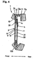
- a ski goggle G includes a goggle frame 1, an elastic band 2 linked with the goggle frame 1, a goggle lens 3 detachably fitted in the goggle frame 1, and a water cut-off filter 4 provided on the goggle lens 3.
- the goggle frame 1 is made up of soft material such as elastic synthetic resin, rubber and the like. As shown in Figs. 1 and 3 , the frame 1 has a lens fitting rim 10, a facial seat 11, and a peripheral wall portion 12 linking the lens fitting rim 10 with the facial seat 11.
- the goggle lens 3 is detachably fitted in the lens fitting rim 10.
- both ends of the facial seat 11 have connection portions 11a with holes for connecting the elastic band 2.
- a contact member 11b made of such as sponge and montplane is attached to the facial seat 11 to provide a comfortable fitting with a wearer's face.
- the peripheral wall portion 12 has top and bottom composing walls and left and right composing walls.
- the top, bottom, left and right composing walls respectively have ventilations 12a, 12b and 12c, and these ventilations are covered with a thin sponge plate S1. Closing the ventilations with the sponge plate prevents snow and dusts other than air from invading into the inside of the goggle.
- the elastic band 2 includes band bodies 20 and 20 that are designed to be elastic.
- the band bodies 20 and 20 respectively attached on the connection parts 11a and 11a are linked together by mean of a buckle 21.
- the goggle lens 3 includes two lenses (i.e. an outer lens 30 and an inner lens 31) of transparent resin, and a water cut-off buffer material 33 for sealing between the entire circumferential edges of the two lenses.
- the lenses 30 and 31 and the water cut-off buffer material 33 are fixed together with a double-sided adhesive tape.
- the two lenses 30 and 31 are disposed in parallel with 2mm distance and the room R therebetween functions as an adiabatic layer.
- the outer and inner lenses 30 and 31 respectively have a thickness of about 0.6 mm and a convex shape in which the central portion protrudes from both end portions.
- the outer lens 30 has holes 30a for a ventilation portion 3a near its upper edge and an outer peripheral rim as a portion to be fitted into the lens fitting rim 10 of the goggle frame 1.
- the inner lens 31 is a little smaller in size than the outer lens 30, and has holes 31 a for the ventilation portion 3a near its upper edge.
- the outer lens 30 has an ultraviolet absorption function or an ultraviolet reflection function in order to cut most of ultraviolet rays.
- the front face of the outer lens 30 has a hard coat 8.
- the front face of the inner lens 31 is applied with a metal film (an inorganic film) 5 of such as silver and chromium, and resulting in a mirror film viewed from a bright side and being semi-transparent viewed from a dark side.
- An antifogging film 7 is further added on the rear face of the inner lens 31.
- a sponge plate S2 provided at portions corresponded to the holes 30a and 31 a for the similar reason why the sponge plate S1 is provided.
- the goggle lens 3 has a pressure adjusting hole h at a portion near its outer edge and off a wearer's visual field.
- the pressure adjusting hole h is covered with a water cut-off filter 4.
- a water repellent permeation sheet is employed as the water cut-off filter 4. This sheet prevents water from passing through buts allows air to pass through.
- the water repellent permeation sheet is obtained by pasting a continuous air hole porous material, for example, a tetrafluorinated ethylene resin textile layer, on a substrate with permeability in sheet form such as nylon cloth.
- the tetrafluorinated ethylene resin textile layer after being stretched, becomes very tough and elastic and has a fine textile structure. Further it has many continuous air holes and a strong water repellent property.
- the average diameter of the holes is 0.2 to 5.0 ⁇ m, an air hole rate is 25 to 95%, and an air flow rate is 0.1 to 3000 (488 in H 2 O) cc/sin/in 2 .
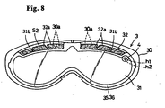
- FIG. 6 to 8 A second embodiment of the optical structure for eyes of the present invention is illustrated in Figs. 6 to 8 .
- a ski goggle G has a goggle frame 1, an elastic band 2 linked with the goggle frame 1, a goggle lens 3 composed of three lenses which are detachably fitted in the goggle frame 1 and a water cut-off filter 4.
- the goggle lens 3 of the second embodiment has three lenses; an outer lens 30, a middle lens 32 and an inner lens 31, respectively being of transparent resin.
- Water cut-off buffer materials 35 and 36 for peripheral sealing are provided between and along the entire circumferential edges of respectively adjacent lenses 30, 32 and 31.
- the adjacent lenses 30 and 32, 32 and 31, and the water cut-off buffer materials 35 and 36 therebetween are respectively pasted together with double-sided adhesive tapes.
- the outer and middle lenses 30 and 32 are disposed in parallel separately by 2mm distance and so the middle and the inner lenses 32 and 31 are.
- the former define a front room R1 and the latter define a rear room R2.
- the rooms R1 and R2 respectively function as adiabatic layers.
- the outer, middle and inner lenses 30, 32 and 31 respectively have a thickness of about 0.6mm and have a convex shape in which a center portion protrudes from end portions.
- the outer lens 30 is larger in size than the other two lenses 32 and 31 and has holes 30a for a ventilation portion 3a near its upper edge. And its outer peripheral rim is a portion to be fitted into a lens fitting rim 10 of the goggle frame 1.
- the middle lens 32 is a little smaller in size than the outer lens 30 and has holes 32a for the ventilation portion 3a near its upper edge.
- the inner lens 31 has a shape with two dent portions 31 b at its upper rim portion corresponding to the foregoing ventilation portion 3a.
- the outer lens 30 has an ultraviolet absorption function or an ultraviolet reflection function for cutting most of ultraviolet rays and a hard coat 8 on its front face.
- a metal film ( inorganic films) 5 of such as silver or chromium is provided on the front faces of the middle and inner lenses 32 and 31 . This makes the film 5 a mirror film viewed from a bright side and semi-transparent viewed from a dark side.
- an antifogging film 7 is added on the rear face of the inner lens 31, the rear face being to confront a wearer's face.
- a sponge plate S2 provided at a portion corresponding to the dent portions 31 b for the same reason why the sponge plate S1 is provided.
- the middle lens 32 has a pressure adjusting hole h1 at a portion near its outer edge and off a wearer's visual field and the inner lens 31 has another pressure adjusting hole h2 at a portion corresponding to the pressure adjusting hole h1.
- the pressure adjusting hole h2 is covered with a water cut-off filter 4.
- the type of filter similar to the first embodiment is employed.
- the pressures of the inside and outside of the goggle lens 3 are equalized through the water cut-off filter 4. This prevents deformation of the outer, middle and inner lenses 30, 32 and 31 and distortion of visual field.
Landscapes
- Health & Medical Sciences (AREA)
- Ophthalmology & Optometry (AREA)
- General Health & Medical Sciences (AREA)
- Heart & Thoracic Surgery (AREA)
- Biomedical Technology (AREA)
- Vascular Medicine (AREA)
- Life Sciences & Earth Sciences (AREA)
- Animal Behavior & Ethology (AREA)
- Engineering & Computer Science (AREA)
- Public Health (AREA)
- Veterinary Medicine (AREA)
- Physics & Mathematics (AREA)
- General Physics & Mathematics (AREA)
- Optics & Photonics (AREA)
- Eyeglasses (AREA)
- Surface Treatment Of Optical Elements (AREA)
Applications Claiming Priority (1)
| Application Number | Priority Date | Filing Date | Title |
|---|---|---|---|
| JP2004347776A JP4446273B2 (ja) | 2004-11-30 | 2004-11-30 | 眼用光学構造物 |
Publications (3)
| Publication Number | Publication Date |
|---|---|
| EP1661534A2 EP1661534A2 (en) | 2006-05-31 |
| EP1661534A3 EP1661534A3 (en) | 2006-07-26 |
| EP1661534B1 true EP1661534B1 (en) | 2011-01-12 |
Family
ID=35911207
Family Applications (1)
| Application Number | Title | Priority Date | Filing Date |
|---|---|---|---|
| EP05026156A Expired - Fee Related EP1661534B1 (en) | 2004-11-30 | 2005-11-30 | Optical structure for eyes |
Country Status (8)
| Country | Link |
|---|---|
| US (1) | US7549180B2 (zh) |
| EP (1) | EP1661534B1 (zh) |
| JP (1) | JP4446273B2 (zh) |
| KR (1) | KR101229736B1 (zh) |
| CN (1) | CN1782784A (zh) |
| DE (1) | DE602005025847D1 (zh) |
| RU (1) | RU2399075C2 (zh) |
| TW (1) | TW200632405A (zh) |
Families Citing this family (27)
| Publication number | Priority date | Publication date | Assignee | Title |
|---|---|---|---|---|
| JP2008062009A (ja) * | 2006-08-10 | 2008-03-21 | Yamamoto Kogaku Co Ltd | 眼用保護具 |
| US7826113B2 (en) * | 2007-03-28 | 2010-11-02 | Konica Minolta Holdings, Inc. | Joined optical member, image display apparatus, and head-mounted display |
| JP5234451B2 (ja) | 2007-10-03 | 2013-07-10 | 山本光学株式会社 | ダブルレンズ |
| JP2009216826A (ja) * | 2008-03-07 | 2009-09-24 | Olympus Imaging Corp | 表示用窓を有する防水機器 |
| PL2271229T3 (pl) * | 2008-04-04 | 2018-11-30 | 3M Innovative Properties Company | Uszczelnienie szybki dla nakrycia głowy |
| JP5088497B2 (ja) | 2008-05-30 | 2012-12-05 | 山本光学株式会社 | 発熱性合成樹脂レンズおよび眼用レンズ物品 |
| US20100002435A1 (en) * | 2008-07-01 | 2010-01-07 | Underwater Lights Usa, Llc | Led light with a diffracting lens |
| US8699141B2 (en) * | 2009-03-13 | 2014-04-15 | Knowles Electronics, Llc | Lens assembly apparatus and method |
| GB2470419B (en) * | 2009-05-22 | 2012-01-18 | Hd Inspiration Holding B V | Outer lens for goggles |
| FR2959121B1 (fr) * | 2010-04-22 | 2013-01-18 | Salomon Sas | Masque de protection pour la pratique de sports de plein air. |
| IT1401182B1 (it) | 2010-07-27 | 2013-07-12 | Geox Spa | Montatura per occhiali, maschere ad uso professionale o sportivo, e simili |
| IT1401768B1 (it) * | 2010-07-28 | 2013-08-02 | Cersal S R L | Occhiale da sci a doppia lente |
| CN102375297B (zh) * | 2010-08-12 | 2014-12-03 | 鸿富锦精密工业(深圳)有限公司 | 相机模组 |
| US9009874B2 (en) | 2011-07-19 | 2015-04-21 | Smith Optics, Inc. | Protective goggles and lens assemblies with adjustable ventilation having reduced visual obstruction |
| WO2014138159A1 (en) | 2013-03-07 | 2014-09-12 | Oakley, Inc. | Regeneratable ant-fogging element for goggle |
| KR101405086B1 (ko) | 2014-03-20 | 2014-06-10 | 주식회사 한국 오.지.케이 | 압력 평형기가 있는 스키 고글 |
| CN105022102A (zh) * | 2014-04-25 | 2015-11-04 | 全舜光学科技有限公司 | 一种光学膜层结构的组合 |
| USD755279S1 (en) * | 2014-10-09 | 2016-05-03 | Swivel Vision Sports LLC | Sports training goggles |
| CN104656273B (zh) * | 2015-02-04 | 2018-03-16 | 深圳市弘祥光电科技有限公司 | 护目镜 |
| CN106597695A (zh) * | 2017-01-16 | 2017-04-26 | 成都迅德科技有限公司 | 一种医用防护眼镜 |
| US20180289547A1 (en) * | 2017-04-07 | 2018-10-11 | Shenzhen Pengyifa Precision Mould Co., Ltd | Ski goggles with replaceable nose bridge support |
| USD841179S1 (en) * | 2017-04-21 | 2019-02-19 | Shenzhen Breo Technology Co., Ltd. | Eye massager |
| CN112040913B (zh) * | 2018-03-02 | 2023-06-20 | 百分百斯皮德莱布有限责任公司 | 护目镜系统和方法 |
| CN109529282A (zh) * | 2019-01-04 | 2019-03-29 | 深圳市瑞源祥橡塑制品有限公司 | 一种水镜 |
| TWM590468U (zh) * | 2019-10-09 | 2020-02-11 | 巍揚實業股份有限公司 | 泳鏡 |
| US11672245B1 (en) * | 2022-08-03 | 2023-06-13 | Darren Mark Teren | Pest control device for residential trash cans and method of use |
| US11812737B1 (en) * | 2022-08-03 | 2023-11-14 | Darren Mark Teren | Wearable protection device for residential and commercial trash cans and method of use |
Family Cites Families (9)
| Publication number | Priority date | Publication date | Assignee | Title |
|---|---|---|---|---|
| FR2052099A6 (zh) * | 1969-07-16 | 1971-04-09 | France Etat | |
| JP2537773B2 (ja) | 1985-04-10 | 1996-09-25 | ホ−ヤ株式会社 | プラスチツク製ミラ−コ−トレンズ |
| FR2650083B1 (fr) | 1989-07-19 | 1991-10-25 | Angenieux P Ets | Verre oculaire destine a equiper une lunette binoculaire de protecti on des yeux contre les rayonnements solaires nocifs |
| US5018223A (en) * | 1989-09-20 | 1991-05-28 | John R. Gregory | Non-fogging goggles |
| KR100223307B1 (ko) * | 1997-07-30 | 1999-10-15 | 박수안 | 헬멧용 훼이스 실드 |
| CA2213803C (en) * | 1997-08-25 | 2000-10-10 | Korea Ogk Co., Ltd. | Face shield for helmet |
| JP4344877B2 (ja) * | 2000-02-22 | 2009-10-14 | 山本光学株式会社 | ゴーグル |
| JP4378584B2 (ja) * | 2000-02-22 | 2009-12-09 | 山本光学株式会社 | ゴーグル |
| US6772448B1 (en) * | 2001-12-14 | 2004-08-10 | Energy Related Devices, Inc. | Non-fogging goggles |
-
2004
- 2004-11-30 JP JP2004347776A patent/JP4446273B2/ja active Active
-
2005
- 2005-11-25 TW TW094141552A patent/TW200632405A/zh not_active IP Right Cessation
- 2005-11-29 KR KR1020050114655A patent/KR101229736B1/ko not_active IP Right Cessation
- 2005-11-29 RU RU2005137021/28A patent/RU2399075C2/ru not_active IP Right Cessation
- 2005-11-30 US US11/291,375 patent/US7549180B2/en active Active
- 2005-11-30 EP EP05026156A patent/EP1661534B1/en not_active Expired - Fee Related
- 2005-11-30 CN CNA2005101285199A patent/CN1782784A/zh active Pending
- 2005-11-30 DE DE602005025847T patent/DE602005025847D1/de active Active
Also Published As
| Publication number | Publication date |
|---|---|
| TWI357513B (zh) | 2012-02-01 |
| KR101229736B1 (ko) | 2013-02-04 |
| TW200632405A (en) | 2006-09-16 |
| RU2005137021A (ru) | 2007-06-10 |
| KR20060060598A (ko) | 2006-06-05 |
| JP2006154571A (ja) | 2006-06-15 |
| EP1661534A3 (en) | 2006-07-26 |
| EP1661534A2 (en) | 2006-05-31 |
| JP4446273B2 (ja) | 2010-04-07 |
| US20060119948A1 (en) | 2006-06-08 |
| CN1782784A (zh) | 2006-06-07 |
| RU2399075C2 (ru) | 2010-09-10 |
| DE602005025847D1 (de) | 2011-02-24 |
| US7549180B2 (en) | 2009-06-23 |
Similar Documents
| Publication | Publication Date | Title |
|---|---|---|
| EP1661534B1 (en) | Optical structure for eyes | |
| JP2006154571A5 (zh) | ||
| EP3290965B1 (en) | Laminated lenses with anti-fogging functionality | |
| US11579470B2 (en) | Lens with anti-fog element | |
| US5928718A (en) | Protective coating for reflective sunglasses | |
| JPWO2008069186A1 (ja) | 車両窓用防曇ガラス、その製造方法、及びその固定構造 | |
| KR20090124954A (ko) | 합성 수지 렌즈 및 눈용 렌즈 물품 | |
| WO2017099800A1 (en) | Eyewear with reflective filters | |
| JP5152597B2 (ja) | 眼用光学構造物 | |
| TWM566341U (zh) | Three-dimensional (3D) anti-fog lens | |
| US20110007394A1 (en) | Anti-fog instrument for swimming goggles | |
| US7278738B2 (en) | Eyeglass lens with non-uniform coatings | |
| JPH088927B2 (ja) | メガネ | |
| EP3796053A1 (en) | Ophthalmic lens, method of manufacturing thereof, and eyewear comprising the ophthalmic lens | |
| CN216718736U (zh) | 一种防雾高清镜头镀膜塑料镜片 | |
| CN218332188U (zh) | 曲面光学镜片 | |
| CN216848375U (zh) | 一种防蓝光眼镜片 | |
| CN220455552U (zh) | 一种ar前后超薄保护镜片 | |
| CN219715781U (zh) | 一种减反射偏光车房镜片 | |
| CN220962046U (zh) | 一种基于自由环面的多膜叠层镜片 | |
| CN213715487U (zh) | 一种防雾镜片 | |
| KR200224711Y1 (ko) | 선글라스용 필름 | |
| TWM602970U (zh) | 鏡面貼合型功能膜片結構 | |
| JPH1152305A (ja) | ファッションレンズ | |
| CA2285612A1 (en) | Coated sunglass lens |
Legal Events
| Date | Code | Title | Description |
|---|---|---|---|
| PUAI | Public reference made under article 153(3) epc to a published international application that has entered the european phase |
Free format text: ORIGINAL CODE: 0009012 |
|
| AK | Designated contracting states |
Kind code of ref document: A2 Designated state(s): AT BE BG CH CY CZ DE DK EE ES FI FR GB GR HU IE IS IT LI LT LU LV MC NL PL PT RO SE SI SK TR |
|
| AX | Request for extension of the european patent |
Extension state: AL BA HR MK YU |
|
| PUAL | Search report despatched |
Free format text: ORIGINAL CODE: 0009013 |
|
| AK | Designated contracting states |
Kind code of ref document: A3 Designated state(s): AT BE BG CH CY CZ DE DK EE ES FI FR GB GR HU IE IS IT LI LT LU LV MC NL PL PT RO SE SI SK TR |
|
| AX | Request for extension of the european patent |
Extension state: AL BA HR MK YU |
|
| 17P | Request for examination filed |
Effective date: 20061218 |
|
| 17Q | First examination report despatched |
Effective date: 20070122 |
|
| AKX | Designation fees paid |
Designated state(s): DE FR IT |
|
| GRAP | Despatch of communication of intention to grant a patent |
Free format text: ORIGINAL CODE: EPIDOSNIGR1 |
|
| GRAS | Grant fee paid |
Free format text: ORIGINAL CODE: EPIDOSNIGR3 |
|
| GRAA | (expected) grant |
Free format text: ORIGINAL CODE: 0009210 |
|
| AK | Designated contracting states |
Kind code of ref document: B1 Designated state(s): DE FR IT |
|
| REF | Corresponds to: |
Ref document number: 602005025847 Country of ref document: DE Date of ref document: 20110224 Kind code of ref document: P |
|
| REG | Reference to a national code |
Ref country code: DE Ref legal event code: R096 Ref document number: 602005025847 Country of ref document: DE Effective date: 20110224 |
|
| PLBE | No opposition filed within time limit |
Free format text: ORIGINAL CODE: 0009261 |
|
| STAA | Information on the status of an ep patent application or granted ep patent |
Free format text: STATUS: NO OPPOSITION FILED WITHIN TIME LIMIT |
|
| 26N | No opposition filed |
Effective date: 20111013 |
|
| PGFP | Annual fee paid to national office [announced via postgrant information from national office to epo] |
Ref country code: FR Payment date: 20111125 Year of fee payment: 7 |
|
| REG | Reference to a national code |
Ref country code: DE Ref legal event code: R097 Ref document number: 602005025847 Country of ref document: DE Effective date: 20111013 |
|
| REG | Reference to a national code |
Ref country code: FR Ref legal event code: ST Effective date: 20130731 |
|
| PG25 | Lapsed in a contracting state [announced via postgrant information from national office to epo] |
Ref country code: IT Free format text: LAPSE BECAUSE OF NON-PAYMENT OF DUE FEES Effective date: 20121130 |
|
| REG | Reference to a national code |
Ref country code: DE Ref legal event code: R119 Ref document number: 602005025847 Country of ref document: DE Effective date: 20130601 |
|
| PG25 | Lapsed in a contracting state [announced via postgrant information from national office to epo] |
Ref country code: DE Free format text: LAPSE BECAUSE OF NON-PAYMENT OF DUE FEES Effective date: 20130601 |
|
| PG25 | Lapsed in a contracting state [announced via postgrant information from national office to epo] |
Ref country code: FR Free format text: LAPSE BECAUSE OF NON-PAYMENT OF DUE FEES Effective date: 20121130 |