EP1661443A1 - Machine avec un dispositif d'accouplement au système d'attelage trois points d'un tracteur - Google Patents
Machine avec un dispositif d'accouplement au système d'attelage trois points d'un tracteur Download PDFInfo
- Publication number
- EP1661443A1 EP1661443A1 EP05110558A EP05110558A EP1661443A1 EP 1661443 A1 EP1661443 A1 EP 1661443A1 EP 05110558 A EP05110558 A EP 05110558A EP 05110558 A EP05110558 A EP 05110558A EP 1661443 A1 EP1661443 A1 EP 1661443A1
- Authority
- EP
- European Patent Office
- Prior art keywords
- hook
- machine according
- coupling
- tractor
- notch
- Prior art date
- Legal status (The legal status is an assumption and is not a legal conclusion. Google has not performed a legal analysis and makes no representation as to the accuracy of the status listed.)
- Granted
Links
Images


Classifications
-
- A—HUMAN NECESSITIES
- A01—AGRICULTURE; FORESTRY; ANIMAL HUSBANDRY; HUNTING; TRAPPING; FISHING
- A01B—SOIL WORKING IN AGRICULTURE OR FORESTRY; PARTS, DETAILS, OR ACCESSORIES OF AGRICULTURAL MACHINES OR IMPLEMENTS, IN GENERAL
- A01B59/00—Devices specially adapted for connection between animals or tractors and agricultural machines or implements
- A01B59/002—Details, component parts
- A01B59/006—Latched hooks
-
- Y—GENERAL TAGGING OF NEW TECHNOLOGICAL DEVELOPMENTS; GENERAL TAGGING OF CROSS-SECTIONAL TECHNOLOGIES SPANNING OVER SEVERAL SECTIONS OF THE IPC; TECHNICAL SUBJECTS COVERED BY FORMER USPC CROSS-REFERENCE ART COLLECTIONS [XRACs] AND DIGESTS
- Y02—TECHNOLOGIES OR APPLICATIONS FOR MITIGATION OR ADAPTATION AGAINST CLIMATE CHANGE
- Y02A—TECHNOLOGIES FOR ADAPTATION TO CLIMATE CHANGE
- Y02A40/00—Adaptation technologies in agriculture, forestry, livestock or agroalimentary production
- Y02A40/10—Adaptation technologies in agriculture, forestry, livestock or agroalimentary production in agriculture
- Y02A40/28—Adaptation technologies in agriculture, forestry, livestock or agroalimentary production in agriculture specially adapted for farming
Definitions
- the present invention relates to a machine comprising a device for coupling to a three-point hitch system of a tractor, said device having in particular two lower mechanisms which are located at the same level and at a certain distance from each other. on the other and which are intended for the attachment to two hydraulically liftable drawbars of the tractor's three-point linkage system.
- Such a machine may be a mower, a brushcutter or a grinder may be used for example in agriculture, forestry or roadside maintenance.
- These machines generally include tools that are offset laterally relative to the tractors so as to work on the sides. The weight of these machines in the offset position tends to destabilize the coupling which can cause a rapid deterioration of the coupling means or cause a loss of control of the position of the tool.
- the present invention aims to overcome the aforementioned disadvantages. It must in particular provide a machine with a simple coupling device and capable of withstanding significant lateral forces.
- each of the two lower coupling mechanisms of the machine is constituted by at least one lug having a notch substantially V-shaped for receiving a fastening means attached to the lower drawbars, said tab further comprising a movable hook movable in a position of immobilization of said hooking means in the corresponding notch.
- the immobilization of the attachment means can advantageously be obtained by its wedging by means of the hook in the tip of the notch.
- This arrangement practically makes it possible to obtain a rigid connection between the machine and the drawbars of the three-point coupling system of the tractor. Such a connection allows to have a better hold of the machine relative to the tractor regardless of the position of the work tool. In addition, this arrangement is simple and therefore low cost. Finally, it degrades neither the ground clearance nor the cantilever of the machine.
- the movable hook which is in the off position is automatically unlocked by the hooking means when it engages in the notch of the tab of the corresponding coupling mechanism. Said hook then moves into the immobilization position by pivoting about an axis under the effect of its own weight. The operation of coupling the machine to the tractor is thus very easy to achieve.
- the attachment means is constituted by a cross member which is connected to the two drawbar of the tractor and which has cylindrical portions housed in the notches of the tabs of the coupling mechanisms of the machine . Said cross member provides better stability to the drawbars.
- the machine according to the invention is a brush cutter. It comprises a frame (1) that can be hooked to the three-point hitch system of a tractor (2).
- This frame (1) has an articulated arm (3) carrying at its end a brushcutter (4). The latter can be moved by means of arms (3) so as to be able to work in different positions more or less distant from the tractor (2).
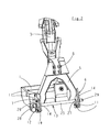
- the machine comprises a coupling device (5) having in particular two lower coupling mechanisms (6 and 7) and an upper coupling mechanism (8).
- the two lower mechanisms (6 and 7) are located at the same level with respect to the ground and to a certain distance from each other. They are intended for coupling to two hitching bars (9) that can be raised hydraulically from the tractor's three-point linkage system (2).
- the third coupling mechanism (8) is located at a higher level and is intended to be connected by a candle (10) to an upper coupling point of the tractor (2).
- Each lower coupling mechanism (6 and 7) consists of two legs (11) parallel and substantially vertical and which are located at a short distance from one another. It is also possible to use only one leg (11) slightly thicker to have equivalent strength. Each of these tabs (11) has a substantially V-shaped notch (12) which is open downward and whose tip is directed upwardly. This notch is intended to receive a hooking means (13) connected to the lower drawbars (9). Said coupling mechanism (6, 7) further comprises a movable hook (14) movable in a position of immobilization of the attachment means (13) in the corresponding notch (12). This hook (14) can be between the two legs (11).
- FIGS. 3 to 5 show in particular that each hook (14) is constituted by a first branch (15) and a second branch (16) which are interconnected so as to form a U.
- Said first branch (15) of hook (14) is articulated on an axis (17) of the lug (11) by means of an oblong orifice (18).
- the second leg (16) of the hook (14) has a width (1) which increases progressively closer to the first leg (15).
- Each lug (11) also has one or two supports (19, 20) for the second leg (16) of the hook (14). These supports (19, 20) consist of studs located on either side of the notch (12).
- the second support (20) serves as reinforcement.
- each lug (11) has a first hole (21) for a retaining pin (22) of the hook (14) in the off position.
- This first orifice (21) is located at the upper part of the tab (11).
- the latter may comprise a second hole (23) for a retaining pin (24) of the hook (14) in the immobilization position.
- This second orifice (23) is located closer to the notch (12) than the first orifice (21).
- the attachment means (13) which is connected to the lower drawbar (9) of the tractor (2) is constituted by a cross member (25).
- This comprises two cylindrical portions (26, 27) accommodating in the notches (12) of the tabs (11). They also have ends (28, 29) which extend beyond said cylindrical portions (26, 27) and which are intended to be connected to the drawbars (9).
- This crossbar (25) may also include attachment points of additional stabilizing members connected to the tractor (2).
- each hook (14) is disengaged upwards by pivoting about its axis (17).
- the second leg (16) of each hook (14) then rests on the first support (19) provided on the lug (11) corresponding.
- the first branch (15) partially extends into the notch (12).
- the length of the portion which thus extends in the notch (12) is substantially equal to the value of the clearance between the axis (17) and the end of the oblong hole (18).
- the crossbar (25) is between the two legs (15 and 16) of the hooks (14).
- the second branches (16) of the hooks (14) then rest on the supports (19 and 20) and, thanks to their progressively increasing width, wedge the crossbar (25) in the tip of the notches (12) in order to to obtain an almost rigid connection.
- This immobilization of the crossbar (25) can be ensured during the work by the engagement of pins (24) in the second orifices (23) of the tabs (11) so that said pins (24) block the hooks (14).
- the candle (10) can be hooked to the third coupling mechanism (8) and to the upper coupling point of the tractor coupling system (2).
- the machine can be used to carry out work such as clearing.
- the hooks (14) To detach the machine from the tractor (2), the hooks (14) must be unlocked by the user and moved upwards about the axes (17) to the off position. They thus release the crossbar (25) which can be disengaged from the bottom of the notches (12).
Landscapes
- Life Sciences & Earth Sciences (AREA)
- Zoology (AREA)
- Engineering & Computer Science (AREA)
- Mechanical Engineering (AREA)
- Soil Sciences (AREA)
- Environmental Sciences (AREA)
- Agricultural Machines (AREA)
Abstract
Description
- La présente invention se rapporte à une machine comportant un dispositif pour l'accouplement à un système d'attelage trois points d'un tracteur, ledit dispositif présentant notamment deux mécanismes inférieurs qui sont situés à un même niveau et à une certaine distance l'une de l'autre et qui sont destinés à l'accrochage à deux barres d'attelage relevables hydrauliquement du système d'attelage trois points du tracteur.
- Une telle machine peut être une faucheuse, une débroussailleuse ou une broyeuse pouvant être employée par exemple dans l'agriculture, la sylviculture ou l'entretien des bords de routes. Ces machines comportent généralement des outils qui sont déportés latéralement par rapport aux tracteurs de manière à pouvoir travailler sur les côtés. Le poids de ces machines en position déportée tend à déstabiliser l'attelage ce qui peut entraîner une rapide détérioration des moyens d'attelage voire provoquer une perte de contrôle de la position de l'outil.
- Pour remédier à cela il est déjà connu dans le brevet FR 2 791 863 d'interposer entre le système d'attelage du tracteur et le dispositif d'accouplement de la machine un mécanisme de stabilisation. Un tel mécanisme est cependant volumineux, ce qui entraîne notamment un éloignement de la machine du tracteur et donc une augmentation du porte-à-faux. De plus, il est relativement onéreux, ce qui fait que certains propriétaires d'une machine à outil déporté n'utilisent pas un tel mécanisme de stabilisation.
- La présente invention a pour but de remédier aux inconvénients pré-cités. Elle doit notamment proposer une machine avec un dispositif d'accouplement simple et capable de résister à d'importants efforts latéraux.
- A cet effet, une importante caractéristique de l'invention consiste en ce que chacun des deux mécanismes d'accouplement inférieurs de la machine est constitué par au moins une patte comportant une encoche sensiblement en forme de V destinée à recevoir un moyen d'accrochage lié aux barres d'attelage inférieures, ladite patte comportant en plus un crochet mobile déplaçable dans une position d'immobilisation dudit moyen d'accrochage dans l'encoche correspondante. L'immobilisation du moyen d'accrochage peut avantageusement être obtenue par son coincement au moyen du crochet dans la pointe de l'encoche. Cet agencement permet pratiquement d'obtenir une liaison rigide entre la machine et les barres d'attelage du système d'attelage trois points du tracteur. Une telle liaison permet d'avoir un meilleur maintien de la machine par rapport au tracteur quelle que soit la position de l'outil de travail. En sus, cet agencement est simple et donc d'un coût peu élevé. Enfin, il ne dégrade ni la garde au sol ni le porte-à-faux de la machine.
- Selon une autre caractéristique de l'invention, le crochet mobile qui se situe dans la position hors service est débloqué automatiquement par le moyen d'accrochage lorsque celui-ci s'engage dans l'encoche de la patte du mécanisme d'accouplement correspondant. Ledit crochet se déplace ensuite dans la position d'immobilisation par pivotement autour d'un axe sous l'effet de son propre poids. L'opération d'accouplement de la machine au tracteur est ainsi très facile à réaliser.
- Selon une autre caractéristique de l'invention le moyen d'accrochage est constitué par une traverse qui est liée aux deux barres d'attelage du tracteur et qui comporte des parties cylindriques se logeant dans les encoches des pattes des mécanismes d'accouplement de la machine. Ladite traverse procure une meilleure stabilité aux barres d'attelage.
- D'autres caractéristiques et avantages de l'invention ressortiront de la description qui va suivre et qui se réfère aux dessins annexés qui représentent, à titre d'exemple non limitatif, une forme de réalisation d'une machine selon l'invention.
- Dans ces dessins :
- la figure 1 représente une vue générale d'une machine selon l'invention attelée à un tracteur,
- la figure 2 représente une vue d'ensemble du dispositif d'accouplement selon l'invention,
- la figure 3 représente une vue de détail du mécanisme d'accouplement de la machine en position hors service,
- la figure 4 représente une vue de détail du mécanisme d'accouplement de la machine en cours d'attelage,
- la figure 5 représente une vue de détail du mécanisme d'accouplement de la machine en position d'immobilisation.
- Telle qu'elle est représentée sur la figure 1, la machine selon l'invention est une débroussailleuse. Elle comporte un bâti (1) pouvant être accroché au système d'attelage trois points d'un tracteur (2). Ce bâti (1) possède un bras articulé (3) portant à son extrémité un outil de débroussaillage (4). Ce dernier peut être déplacé à l'aide de bras (3) de manière à pouvoir travailler dans différentes positions plus ou moins éloignées du tracteur (2).
- Comme cela ressort de la figure 2, la machine comporte un dispositif d'accouplement (5) présentant notamment deux mécanismes d'accouplement inférieurs (6 et 7) et un mécanisme d'accouplement supérieur (8). Les deux mécanismes inférieurs (6 et 7) sont situés au même niveau par rapport au sol et à une certaine dstance l'un de l'autre. Ils sont destinés à l'accouplement à deux barres d'attelage (9) relevables hydrauliquement du système d'attelage trois points du tracteur (2). Le troisième mécanisme d'accouplement (8) se situe à un niveau supérieur et est destiné à être relié par une chandelle (10) à un point d'accouplement supérieur du tracteur (2).
- Chaque mécanisme d'accouplement inférieur (6 et 7) est constitué par deux pattes (11) parallèles et sensiblement verticales et qui sont situées à une faible distance l'une de l'autre. Il est aussi possible de n'utiliser qu'une seule patte (11) légèrement plus épaisse pour avoir une résistance équivalente. Chacune de ces pattes (11) comporte une encoche (12) sensiblement en forme de V qui est ouverte vers le bas et dont la pointe est dirigée vers le haut. Cette encoche est destinée à recevoir un moyen d'accrochage (13) lié aux barres d'attelage inférieures (9). Ledit mécanisme d'accouplement (6, 7) comporte en plus un crochet mobile (14) déplaçable dans une position d'immobilisation du moyen d'accrochage (13) dans l'encoche (12) correspondante. Ce crochet (14) peut se situer entre les deux pattes (11).
- On voit notamment sur les figures 3 à 5 que chaque crochet (14) est constitué par une première branche (15) et une deuxième branche (16) qui sont reliées entre elles de manière à former un U. Ladite première branche (15) du crochet (14) est articulée sur un axe (17) de la patte (11) au moyen d'un orifice oblong (18). La deuxième branche (16) du crochet (14) possède une largeur (1) qui augmente progressivement en se rapprochant de la première branche (15). Chaque patte (11) comporte également un ou deux appuis (19, 20) pour la deuxième branche (16) du crochet (14). Ces appuis (19, 20) sont constitués par des plots situés de part et d'autre de l'encoche (12). Le deuxième appui (20) sert de renfort. En sus, chaque patte (11) comporte un premier orifice (21) pour une broche de retenue (22) du crochet (14) en position hors service. Ce premier orifice (21) se situe à la partie supérieure de la patte (11). Cette dernière peut comporter un deuxième orifice (23) pour une broche de retenue (24) du crochet (14) en position d'immobilisation. Ce deuxième orifice (23) se situe plus près de l'encoche (12) que le premier orifice (21).
- Conformément à l'exemple représenté sur la figure 2, le moyen d'accrochage (13) qui est lié aux barres d'attelage inférieures (9) du tracteur (2) est constitué par une traverse (25). Celle-ci comporte deux parties cylindriques (26, 27) se logeant dans les encoches (12) des pattes (11). Elles comportent également des extrémités (28, 29) qui s'étendent au-delà desdites parties cylindriques (26, 27) et qui sont destinées à être reliées aux barres d'attelage (9). Cette traverse (25) peut également comporter des points d'accrochage d'organes de stabilisation supplémentaires reliés au tracteur (2).
- Pour effectuer l'accrochage de la machine selon l'invention à un tracteur il faut placer chaque crochet (14) dans la position hors service telle que représentée sur la figure 3. Dans cette position chaque crochet (14) est dégagé vers le haut par pivotement autour de son axe (17). La deuxième branche (16) de chaque crochet (14) repose alors sur le premier appui (19) prévu sur la patte (11) correspondante. La première branche (15) s'étend partiellement dans l'encoche (12). La longueur de la partie qui s'étend ainsi dans l'encoche (12) est sensiblement égale à la valeur du jeu entre l'axe (17) et l'extrémité du trou oblong (18). Cette position du crochet (14) peut être assurée pour un maintien de longue durée au moyen de la broche (22) qui est engagée dans le premier orifice (21) de sorte qu'elle bloque ledit crochet (14). Ensuite, la traverse (25) qui est liée aux barres d'attelage inférieures (9) est amenée dans les encoches (12) et est déplacée vers le haut à l'aide desdites barres d'attelage (9). Lorsque les parties cylindriques (26, 27) de cette traverse (25) arrivent dans la pointe des encoches (12) elles poussent les crochets (14) et les dégagent vers le haut sur une distance sensiblement égale à la valeur du jeu dans les trous oblongs (18) (figure 4). De cette manière, les crochets (14) sont éloignés des premiers appuis (19) et, si les broches de retenue (22) sont retirées des premiers orifices (21), ils pivotent automatiquement vers le bas sous l'effet de leur propre poids, autour des axes (17), jusque dans la position d'immobilisation représentée sur la figure 5. Dans cette position, la traverse (25) se situe entre les deux branches (15 et 16) des crochets (14). Les deuxièmes branches (16) des crochets (14) s'appuient alors sur les appuis (19 et 20) et, grâce à leur largeur qui augmente progressivement, coincent la traverse (25) dans la pointe des encoches (12) en vue d'obtenir une liaison quasi rigide. Cette immobilisation de la traverse (25) peut être assurée durant le travail par l'engagement de broches (24) dans les deuxièmes orifices (23) des pattes (11) de sorte que lesdites broches (24) bloquent les crochets (14). Enfin, la chandelle (10) peut être accrochée au troisième mécanisme d'accouplement (8) et au point d'attelage supérieur du système d'attelage du tracteur (2). Ainsi accouplée, la machine peut être utilisée pour effectuer les travaux tels que le débroussaillage.
- Pour détacher la machine du tracteur (2), les crochets (14) doivent être débloqués par l'utilisateur et être déplacés vers le haut autour des axes (17) dans la position hors service. Ils libèrent ainsi la traverse (25) qui pourra être dégagée par le bas des encoches (12).
- Il est bien évident que l'invention n'est pas limitée au mode de réalisation décrit et représenté sur les dessins annexés. Des modifications restent possibles, notamment en ce qui concerne la constitution des divers éléments ou par substitution d'équivalents techniques, sans pour autant sortir du domaine de protection.
Claims (13)
- Machine comportant un dispositif (5) pour l'accouplement à un système d'attelage trois points d'un tracteur (2), ledit dispositif d'accouplement (5) présentant notamment deux mécanismes d'accouplement inférieurs (6 et 7) qui sont situés à un même niveau et à une certaine distance l'un de l'autre et qui sont destinés à l'accrochage à deux barres d'attelage inférieures (9) relevables hydrauliquement du système d'attelage trois points, chaque mécanisme d'accouplement inférieur (6, 7) étant constitué par au moins une patte (11) comportant, d'une part, une encoche (12) sensiblement en forme de V destinée à recevoir un moyen d'accrochage (13) lié aux barres d'attelage inférieures (9) et, d'autre part, un crochet mobile (14), caractérisée par le fait que le crochet mobile (14) est déplaçable dans une position d'immobilisation par coincement du moyen d'accrochage (13) dans l'encoche (12) correspondante.
- Machine selon la revendication 1, caractérisée par le fait que chaque patte (11) est sensiblement verticale et comporte une encoche (12) en forme de V avec la pointe dirigée vers le haut.
- Machine selon la revendication 1 ou 2, caractérisée par le fait que le crochet (14) est constitué par une première branche (15) et une deuxième branche (16) qui sont reliées entre elles de manière à former un U.
- Machine selon la revendication 3, caractérisée par le fait que la première branche (15) du crochet (14) est articulée sur un axe (17) de la patte (11) correspondante au moyen d'un orifice oblong (18).
- Machine selon la revendication 3, caractérisée par le fait que la deuxième branche (16) du crochet (14) possède une largeur (1) qui augmente progressivement en se rapprochant de la première branche (15).
- Machine selon la revendication 5, caractérisée par le fait que dans la position d'immobilisation, le moyen d'accrochage (13) se situe entre les deux branches (15 et 16) du crochet (14) et est coincé dans la pointe de l'encoche (12) par la deuxième branche (16).
- Machine selon l'une quelconque des revendications 1 à 6, caractérisée par le fait que chaque patte (11) comporte au moins un appui (19, 20) pour la deuxième branche (16) du crochet (14).
- Machine selon l'une quelconque des revendications précédentes, caractérisée par le fait que le crochet (14) est déplaçable autour de l'axe (17) dans une position hors service dans laquelle la première branche (15) s'étend partiellement dans l'encoche (12).
- Machine selon la revendication 8, caractérisée par le fait que le crochet (14) est déblocable automatiquement par le moyen d'accrochage (13) s'engageant dans la pointe de l'encoche (12) et qu'il est déplaçable dans la position d'immobilisation autour de l'axe (17) sous l'effet de son propre poids.
- Machine selon l'une quelconque des revendications précédentes, caractérisée par le fait que chaque patte (11) comporte au moins un premier orifice (21) pour une broche de retenue (22) du crochet (14) en position hors service.
- Machine selon l'une quelconque des revendications précédentes, caractérisée par le fait que chaque patte (11) comporte au moins un deuxième orifice (23) pour une broche de retenue (24) du crochet (14) en position d'immobilisation.
- Machine selon l'une quelconque des revendications précédentes, caractérisée par le fait que le moyen d'accrochage (13) est constitué par une traverse (25) liée aux deux barres d'attelage (9) du tracteur (2) et comportant des parties cylindriques (26, 27) se logeant dans les encoches (12) des pattes (11).
- Machine selon l'une quelconque des revendications précédentes, caractérisée par le fait qu'elle comporte un troisième dispositif d'accouplement (8) relié par une chandelle (10) à un point d'accouplement supérieur du tracteur (2).
Applications Claiming Priority (1)
| Application Number | Priority Date | Filing Date | Title |
|---|---|---|---|
| FR0452811A FR2878402B1 (fr) | 2004-11-30 | 2004-11-30 | Machine avec un dispositif d'accouplement au systeme d'attelage trois points d'un tracteur |
Publications (2)
| Publication Number | Publication Date |
|---|---|
| EP1661443A1 true EP1661443A1 (fr) | 2006-05-31 |
| EP1661443B1 EP1661443B1 (fr) | 2008-01-16 |
Family
ID=34951618
Family Applications (1)
| Application Number | Title | Priority Date | Filing Date |
|---|---|---|---|
| EP05110558A Expired - Lifetime EP1661443B1 (fr) | 2004-11-30 | 2005-11-09 | Machine avec un dispositif d'accouplement au système d'attelage trois points d'un tracteur |
Country Status (4)
| Country | Link |
|---|---|
| EP (1) | EP1661443B1 (fr) |
| AT (1) | ATE383738T1 (fr) |
| DE (1) | DE602005004358T2 (fr) |
| FR (1) | FR2878402B1 (fr) |
Cited By (1)
| Publication number | Priority date | Publication date | Assignee | Title |
|---|---|---|---|---|
| EP1932411A1 (fr) * | 2006-12-14 | 2008-06-18 | CNH Italia S.p.A. | Verrou automatique pour couplage rapide de crochet en trois points et module de connexion PTO |
Citations (4)
| Publication number | Priority date | Publication date | Assignee | Title |
|---|---|---|---|---|
| US816218A (en) * | 1905-10-23 | 1906-03-27 | Reeves & Co | Coupling. |
| AT341255B (de) * | 1975-10-14 | 1978-01-25 | Prillinger Karl | Vorrichtung zum anbau landwirtschaftlicher gerate an ackerschleppern |
| US4331347A (en) * | 1980-02-19 | 1982-05-25 | Madden Lem A | Three-point hookup apparatus |
| DE4136515A1 (de) * | 1991-11-06 | 1993-03-18 | Wiedenmann Gmbh | Kupplungsvorrichtung fuer anbaugeraete an einem traegerfahrzeug |
-
2004
- 2004-11-30 FR FR0452811A patent/FR2878402B1/fr not_active Expired - Fee Related
-
2005
- 2005-11-09 DE DE602005004358T patent/DE602005004358T2/de not_active Expired - Lifetime
- 2005-11-09 EP EP05110558A patent/EP1661443B1/fr not_active Expired - Lifetime
- 2005-11-09 AT AT05110558T patent/ATE383738T1/de not_active IP Right Cessation
Patent Citations (4)
| Publication number | Priority date | Publication date | Assignee | Title |
|---|---|---|---|---|
| US816218A (en) * | 1905-10-23 | 1906-03-27 | Reeves & Co | Coupling. |
| AT341255B (de) * | 1975-10-14 | 1978-01-25 | Prillinger Karl | Vorrichtung zum anbau landwirtschaftlicher gerate an ackerschleppern |
| US4331347A (en) * | 1980-02-19 | 1982-05-25 | Madden Lem A | Three-point hookup apparatus |
| DE4136515A1 (de) * | 1991-11-06 | 1993-03-18 | Wiedenmann Gmbh | Kupplungsvorrichtung fuer anbaugeraete an einem traegerfahrzeug |
Cited By (1)
| Publication number | Priority date | Publication date | Assignee | Title |
|---|---|---|---|---|
| EP1932411A1 (fr) * | 2006-12-14 | 2008-06-18 | CNH Italia S.p.A. | Verrou automatique pour couplage rapide de crochet en trois points et module de connexion PTO |
Also Published As
| Publication number | Publication date |
|---|---|
| ATE383738T1 (de) | 2008-02-15 |
| DE602005004358T2 (de) | 2009-01-08 |
| FR2878402A1 (fr) | 2006-06-02 |
| FR2878402B1 (fr) | 2008-05-23 |
| DE602005004358D1 (de) | 2008-03-06 |
| EP1661443B1 (fr) | 2008-01-16 |
Similar Documents
| Publication | Publication Date | Title |
|---|---|---|
| EP0511922B1 (fr) | Machine de coupe perfectionnée avec structure d'attelage pivotante | |
| EP1774106B1 (fr) | Dispositif d'accouplement d'un chargeur à un tracteur | |
| FR3055082A1 (fr) | Machine agricole comportant un dispositif d'assistance au repliage | |
| EP0787422B1 (fr) | Faucheuse | |
| EP4147546B1 (fr) | Charrue réversible présentant une sécurité améliorée lors des changements de configuration | |
| EP1661443B1 (fr) | Machine avec un dispositif d'accouplement au système d'attelage trois points d'un tracteur | |
| FR2563685A1 (fr) | Faucheuse | |
| EP1586709B1 (fr) | Cadre porte-outil à caractère polyvalent pour chargeur, notamment pour chargeur à usage agricole | |
| EP1586708B1 (fr) | Dispositif de verrouillage d'un outil sur le cadre porte-outil d'un chargeur, notamment à usage agricole | |
| EP2786648B1 (fr) | Dispositif d'attelage perfectionné | |
| EP3713390A1 (fr) | Machine agricole avec un système de sécurité à cinématique de déclenchement améliorée | |
| FR2969674A1 (fr) | Cadre porte-outil pour chargeur, notamment pour chargeur equipant un engin agricole, permettant de securiser le verrouillage d'un outil | |
| BE1028453B1 (fr) | Dispositif d'articulation d'eparpilleur de lisier | |
| CA2478127A1 (fr) | Machine agricole destinee a etre attelee a une barre d'attelage d'un vehicule tracteur | |
| FR2575027A1 (fr) | Dispositif d'attelage pour chargeur frontal de tracteur | |
| FR2504347A1 (fr) | Perfectionnements aux charrues reversibles | |
| FR2723706A1 (fr) | Dispositif pour fendre des billes en buches | |
| FR2803560A1 (fr) | Dispositif d'attelage de timon de remorque a un crochet de tracteur agricole | |
| FR2791863A1 (fr) | Mecanisme de stabilisation d'un dispositif de relevage d'un tracteur | |
| FR2519835A1 (fr) | Dispositif d'attelage pour instrument agricole tracte | |
| FR2910228A1 (fr) | Ensemble de train roulant pour outils agricoles portes. | |
| EP1256268B1 (fr) | Dispositif d'attelage d'un semoir à une machine de travail du sol, à biellettes de fixation | |
| FR2790636A1 (fr) | Machine agricole et notamment machine destinee a tasser le sol | |
| BE847520A (fr) | Perfectionnement a l'accouplement d'une machine agricole a un tracteur. | |
| FR2536499A1 (fr) | Dispositif pour l'escamotage de roues de batis de machines |
Legal Events
| Date | Code | Title | Description |
|---|---|---|---|
| PUAI | Public reference made under article 153(3) epc to a published international application that has entered the european phase |
Free format text: ORIGINAL CODE: 0009012 |
|
| AK | Designated contracting states |
Kind code of ref document: A1 Designated state(s): AT BE BG CH CY CZ DE DK EE ES FI FR GB GR HU IE IS IT LI LT LU LV MC NL PL PT RO SE SI SK TR |
|
| AX | Request for extension of the european patent |
Extension state: AL BA HR MK YU |
|
| 17P | Request for examination filed |
Effective date: 20061130 |
|
| 17Q | First examination report despatched |
Effective date: 20070105 |
|
| AKX | Designation fees paid |
Designated state(s): AT BE BG CH CY CZ DE DK EE ES FI FR GB GR HU IE IS IT LI LT LU LV MC NL PL PT RO SE SI SK TR |
|
| GRAP | Despatch of communication of intention to grant a patent |
Free format text: ORIGINAL CODE: EPIDOSNIGR1 |
|
| GRAS | Grant fee paid |
Free format text: ORIGINAL CODE: EPIDOSNIGR3 |
|
| GRAA | (expected) grant |
Free format text: ORIGINAL CODE: 0009210 |
|
| AK | Designated contracting states |
Kind code of ref document: B1 Designated state(s): AT BE BG CH CY CZ DE DK EE ES FI FR GB GR HU IE IS IT LI LT LU LV MC NL PL PT RO SE SI SK TR |
|
| REG | Reference to a national code |
Ref country code: GB Ref legal event code: FG4D Free format text: NOT ENGLISH |
|
| REG | Reference to a national code |
Ref country code: CH Ref legal event code: EP |
|
| REG | Reference to a national code |
Ref country code: IE Ref legal event code: FG4D Free format text: LANGUAGE OF EP DOCUMENT: FRENCH |
|
| REF | Corresponds to: |
Ref document number: 602005004358 Country of ref document: DE Date of ref document: 20080306 Kind code of ref document: P |
|
| GBT | Gb: translation of ep patent filed (gb section 77(6)(a)/1977) |
Effective date: 20080318 |
|
| PG25 | Lapsed in a contracting state [announced via postgrant information from national office to epo] |
Ref country code: NL Free format text: LAPSE BECAUSE OF FAILURE TO SUBMIT A TRANSLATION OF THE DESCRIPTION OR TO PAY THE FEE WITHIN THE PRESCRIBED TIME-LIMIT Effective date: 20080116 |
|
| NLV1 | Nl: lapsed or annulled due to failure to fulfill the requirements of art. 29p and 29m of the patents act | ||
| PG25 | Lapsed in a contracting state [announced via postgrant information from national office to epo] |
Ref country code: IS Free format text: LAPSE BECAUSE OF FAILURE TO SUBMIT A TRANSLATION OF THE DESCRIPTION OR TO PAY THE FEE WITHIN THE PRESCRIBED TIME-LIMIT Effective date: 20080516 Ref country code: FI Free format text: LAPSE BECAUSE OF FAILURE TO SUBMIT A TRANSLATION OF THE DESCRIPTION OR TO PAY THE FEE WITHIN THE PRESCRIBED TIME-LIMIT Effective date: 20080116 Ref country code: LT Free format text: LAPSE BECAUSE OF FAILURE TO SUBMIT A TRANSLATION OF THE DESCRIPTION OR TO PAY THE FEE WITHIN THE PRESCRIBED TIME-LIMIT Effective date: 20080116 Ref country code: ES Free format text: LAPSE BECAUSE OF FAILURE TO SUBMIT A TRANSLATION OF THE DESCRIPTION OR TO PAY THE FEE WITHIN THE PRESCRIBED TIME-LIMIT Effective date: 20080427 |
|
| PG25 | Lapsed in a contracting state [announced via postgrant information from national office to epo] |
Ref country code: AT Free format text: LAPSE BECAUSE OF FAILURE TO SUBMIT A TRANSLATION OF THE DESCRIPTION OR TO PAY THE FEE WITHIN THE PRESCRIBED TIME-LIMIT Effective date: 20080116 Ref country code: BG Free format text: LAPSE BECAUSE OF FAILURE TO SUBMIT A TRANSLATION OF THE DESCRIPTION OR TO PAY THE FEE WITHIN THE PRESCRIBED TIME-LIMIT Effective date: 20080416 |
|
| PG25 | Lapsed in a contracting state [announced via postgrant information from national office to epo] |
Ref country code: PT Free format text: LAPSE BECAUSE OF FAILURE TO SUBMIT A TRANSLATION OF THE DESCRIPTION OR TO PAY THE FEE WITHIN THE PRESCRIBED TIME-LIMIT Effective date: 20080616 Ref country code: LV Free format text: LAPSE BECAUSE OF FAILURE TO SUBMIT A TRANSLATION OF THE DESCRIPTION OR TO PAY THE FEE WITHIN THE PRESCRIBED TIME-LIMIT Effective date: 20080116 Ref country code: SI Free format text: LAPSE BECAUSE OF FAILURE TO SUBMIT A TRANSLATION OF THE DESCRIPTION OR TO PAY THE FEE WITHIN THE PRESCRIBED TIME-LIMIT Effective date: 20080116 Ref country code: PL Free format text: LAPSE BECAUSE OF FAILURE TO SUBMIT A TRANSLATION OF THE DESCRIPTION OR TO PAY THE FEE WITHIN THE PRESCRIBED TIME-LIMIT Effective date: 20080116 |
|
| REG | Reference to a national code |
Ref country code: IE Ref legal event code: FD4D |
|
| PG25 | Lapsed in a contracting state [announced via postgrant information from national office to epo] |
Ref country code: DK Free format text: LAPSE BECAUSE OF FAILURE TO SUBMIT A TRANSLATION OF THE DESCRIPTION OR TO PAY THE FEE WITHIN THE PRESCRIBED TIME-LIMIT Effective date: 20080116 Ref country code: CZ Free format text: LAPSE BECAUSE OF FAILURE TO SUBMIT A TRANSLATION OF THE DESCRIPTION OR TO PAY THE FEE WITHIN THE PRESCRIBED TIME-LIMIT Effective date: 20080116 Ref country code: SE Free format text: LAPSE BECAUSE OF FAILURE TO SUBMIT A TRANSLATION OF THE DESCRIPTION OR TO PAY THE FEE WITHIN THE PRESCRIBED TIME-LIMIT Effective date: 20080416 Ref country code: IE Free format text: LAPSE BECAUSE OF FAILURE TO SUBMIT A TRANSLATION OF THE DESCRIPTION OR TO PAY THE FEE WITHIN THE PRESCRIBED TIME-LIMIT Effective date: 20080116 Ref country code: SK Free format text: LAPSE BECAUSE OF FAILURE TO SUBMIT A TRANSLATION OF THE DESCRIPTION OR TO PAY THE FEE WITHIN THE PRESCRIBED TIME-LIMIT Effective date: 20080116 |
|
| PLBE | No opposition filed within time limit |
Free format text: ORIGINAL CODE: 0009261 |
|
| STAA | Information on the status of an ep patent application or granted ep patent |
Free format text: STATUS: NO OPPOSITION FILED WITHIN TIME LIMIT |
|
| PG25 | Lapsed in a contracting state [announced via postgrant information from national office to epo] |
Ref country code: RO Free format text: LAPSE BECAUSE OF FAILURE TO SUBMIT A TRANSLATION OF THE DESCRIPTION OR TO PAY THE FEE WITHIN THE PRESCRIBED TIME-LIMIT Effective date: 20080116 |
|
| 26N | No opposition filed |
Effective date: 20081017 |
|
| PG25 | Lapsed in a contracting state [announced via postgrant information from national office to epo] |
Ref country code: EE Free format text: LAPSE BECAUSE OF FAILURE TO SUBMIT A TRANSLATION OF THE DESCRIPTION OR TO PAY THE FEE WITHIN THE PRESCRIBED TIME-LIMIT Effective date: 20080116 |
|
| BERE | Be: lapsed |
Owner name: KUHN-AUDUREAU S.A. Effective date: 20081130 |
|
| PG25 | Lapsed in a contracting state [announced via postgrant information from national office to epo] |
Ref country code: MC Free format text: LAPSE BECAUSE OF NON-PAYMENT OF DUE FEES Effective date: 20081130 |
|
| PG25 | Lapsed in a contracting state [announced via postgrant information from national office to epo] |
Ref country code: CY Free format text: LAPSE BECAUSE OF FAILURE TO SUBMIT A TRANSLATION OF THE DESCRIPTION OR TO PAY THE FEE WITHIN THE PRESCRIBED TIME-LIMIT Effective date: 20080116 |
|
| PG25 | Lapsed in a contracting state [announced via postgrant information from national office to epo] |
Ref country code: BE Free format text: LAPSE BECAUSE OF NON-PAYMENT OF DUE FEES Effective date: 20081130 |
|
| REG | Reference to a national code |
Ref country code: CH Ref legal event code: PL |
|
| PG25 | Lapsed in a contracting state [announced via postgrant information from national office to epo] |
Ref country code: HU Free format text: LAPSE BECAUSE OF FAILURE TO SUBMIT A TRANSLATION OF THE DESCRIPTION OR TO PAY THE FEE WITHIN THE PRESCRIBED TIME-LIMIT Effective date: 20080717 Ref country code: LU Free format text: LAPSE BECAUSE OF NON-PAYMENT OF DUE FEES Effective date: 20081109 |
|
| PG25 | Lapsed in a contracting state [announced via postgrant information from national office to epo] |
Ref country code: TR Free format text: LAPSE BECAUSE OF FAILURE TO SUBMIT A TRANSLATION OF THE DESCRIPTION OR TO PAY THE FEE WITHIN THE PRESCRIBED TIME-LIMIT Effective date: 20080116 |
|
| PG25 | Lapsed in a contracting state [announced via postgrant information from national office to epo] |
Ref country code: LI Free format text: LAPSE BECAUSE OF NON-PAYMENT OF DUE FEES Effective date: 20091130 Ref country code: CH Free format text: LAPSE BECAUSE OF NON-PAYMENT OF DUE FEES Effective date: 20091130 Ref country code: GR Free format text: LAPSE BECAUSE OF FAILURE TO SUBMIT A TRANSLATION OF THE DESCRIPTION OR TO PAY THE FEE WITHIN THE PRESCRIBED TIME-LIMIT Effective date: 20080417 |
|
| REG | Reference to a national code |
Ref country code: FR Ref legal event code: PLFP Year of fee payment: 11 |
|
| REG | Reference to a national code |
Ref country code: FR Ref legal event code: PLFP Year of fee payment: 12 |
|
| REG | Reference to a national code |
Ref country code: FR Ref legal event code: PLFP Year of fee payment: 13 |
|
| PGFP | Annual fee paid to national office [announced via postgrant information from national office to epo] |
Ref country code: DE Payment date: 20241127 Year of fee payment: 20 |
|
| PGFP | Annual fee paid to national office [announced via postgrant information from national office to epo] |
Ref country code: GB Payment date: 20241127 Year of fee payment: 20 |
|
| PGFP | Annual fee paid to national office [announced via postgrant information from national office to epo] |
Ref country code: FR Payment date: 20241128 Year of fee payment: 20 |
|
| PGFP | Annual fee paid to national office [announced via postgrant information from national office to epo] |
Ref country code: IT Payment date: 20241122 Year of fee payment: 20 |
|
| REG | Reference to a national code |
Ref country code: DE Ref legal event code: R071 Ref document number: 602005004358 Country of ref document: DE |
|
| REG | Reference to a national code |
Ref country code: GB Ref legal event code: PE20 Expiry date: 20251108 |