EP1660929B1 - Optisches akkomodatives kompensationssystem - Google Patents
Optisches akkomodatives kompensationssystem Download PDFInfo
- Publication number
- EP1660929B1 EP1660929B1 EP04786292A EP04786292A EP1660929B1 EP 1660929 B1 EP1660929 B1 EP 1660929B1 EP 04786292 A EP04786292 A EP 04786292A EP 04786292 A EP04786292 A EP 04786292A EP 1660929 B1 EP1660929 B1 EP 1660929B1
- Authority
- EP
- European Patent Office
- Prior art keywords
- lens
- lenses
- eye
- addition
- optical system
- Prior art date
- Legal status (The legal status is an assumption and is not a legal conclusion. Google has not performed a legal analysis and makes no representation as to the accuracy of the status listed.)
- Not-in-force
Links
Images


Classifications
-
- G—PHYSICS
- G02—OPTICS
- G02C—SPECTACLES; SUNGLASSES OR GOGGLES INSOFAR AS THEY HAVE THE SAME FEATURES AS SPECTACLES; CONTACT LENSES
- G02C7/00—Optical parts
- G02C7/02—Lenses; Lens systems ; Methods of designing lenses
- G02C7/06—Lenses; Lens systems ; Methods of designing lenses bifocal; multifocal ; progressive
- G02C7/061—Spectacle lenses with progressively varying focal power
- G02C7/063—Shape of the progressive surface
- G02C7/066—Shape, location or size of the viewing zones
-
- A—HUMAN NECESSITIES
- A61—MEDICAL OR VETERINARY SCIENCE; HYGIENE
- A61F—FILTERS IMPLANTABLE INTO BLOOD VESSELS; PROSTHESES; DEVICES PROVIDING PATENCY TO, OR PREVENTING COLLAPSING OF, TUBULAR STRUCTURES OF THE BODY, e.g. STENTS; ORTHOPAEDIC, NURSING OR CONTRACEPTIVE DEVICES; FOMENTATION; TREATMENT OR PROTECTION OF EYES OR EARS; BANDAGES, DRESSINGS OR ABSORBENT PADS; FIRST-AID KITS
- A61F2/00—Filters implantable into blood vessels; Prostheses, i.e. artificial substitutes or replacements for parts of the body; Appliances for connecting them with the body; Devices providing patency to, or preventing collapsing of, tubular structures of the body, e.g. stents
- A61F2/02—Prostheses implantable into the body
- A61F2/14—Eye parts, e.g. lenses, corneal implants; Implanting instruments specially adapted therefor; Artificial eyes
- A61F2/16—Intraocular lenses
- A61F2/1613—Intraocular lenses having special lens configurations, e.g. multipart lenses; having particular optical properties, e.g. pseudo-accommodative lenses, lenses having aberration corrections, diffractive lenses, lenses for variably absorbing electromagnetic radiation, lenses having variable focus
- A61F2/1616—Pseudo-accommodative, e.g. multifocal or enabling monovision
- A61F2/1618—Multifocal lenses
-
- G—PHYSICS
- G02—OPTICS
- G02C—SPECTACLES; SUNGLASSES OR GOGGLES INSOFAR AS THEY HAVE THE SAME FEATURES AS SPECTACLES; CONTACT LENSES
- G02C7/00—Optical parts
- G02C7/02—Lenses; Lens systems ; Methods of designing lenses
- G02C7/06—Lenses; Lens systems ; Methods of designing lenses bifocal; multifocal ; progressive
- G02C7/061—Spectacle lenses with progressively varying focal power
Definitions
- the present invention relates generally to the compensation or correction of disorders of vision, and more particularly to cases in which the accommodative function of the eye is deficient. It concerns concretely an optical system implemented to compensate for this deficiency, as well as visual equipment incorporating this system.
- an optical compensation or visual correction system can involve two main types of lenses.
- An aperture lens is designed to exert the optical function that gives it its corrective or compensating power in or against the eye. It is typically an intraocular lens or a corneal contact lens. The optical function exerted on the eye such an opening lens depends on the opening of the pupil, but is independent of the gaze direction.
- a field lens is designed to exert its optical function at a distance from the eye. It is typically a spectacle lens mounted on a mount placed on the nose of the wearer. It can also be a monocle. The optical function exerted on the eye such a field lens depends on the direction of gaze, but is independent of the opening of the pupil.
- optical correction systems incorporating lenses belonging to one of the two aforementioned types, excluding lenses of the other type. More rarely, in specific cases that will be discussed later, it may happen that the two types of lenses are combined within the same optical correction system.
- the present invention specifically relates to such a hybrid system and proposes its use in the following context.
- the present invention is more particularly concerned with the loss of accommodation, whether partial or total.
- Accommodation is the process by which the eye focuses on objects more or less close together and thus allows objects to be seen successively and clearly, while they are located at different distances, clinically referred to as sighting or viewing distances. job.
- the phenomenon of accommodation is based on a controlled deformation of the lens causing a change in curvature of the surfaces of the natural lens formed by the lens under the effect of tension or relaxation of the zonule.
- the retinal image becomes blurred and the macular diffusion circle triggers a reflex contraction of the circular portion of the ciliary muscle.
- This contraction of the ciliary muscle relaxes the tensions of the zonule and allows the crystalline lens to round, with an increase in the sagittal diameter and a decrease in the frontal diameter resulting in an increase in the spherical power of the lens.
- the ciliary muscle is relaxed and the zonule is under tension, the lens flattens.
- the accommodative function of the eye can be affected on two main occasions.
- presbyopia is not an ametropia, but is added to the possible pre-existing ametropia of the patient.
- the presbyopic must resort to one or more visual equipment which, in addition to the correction of its possible ametropia and astigmatism, compensate for this deficiency.
- Several solutions are available to him. It can carry either several pairs of single-focus field glasses, from which it chooses one that is adapted to the viewing distance that interests it at a given moment, or a single pair of glasses with multifocal field lenses preferably progressive, or even a pair of contact lenses, that is to say, opening lenses, multifocal.
- a multifocal lens has a plurality of spherical foci or powers which differ according to the area of the lens considered.
- the power varies according to the direction of the gaze, with far vision in the top of the glass and near-down vision.
- multifocal contact lenses the multiplicity of foci provides a focus or caustic depth that renders the patient's overall visual system a pseudo accommodation. It is concomitantly formed on the retina several images from different areas of near vision, near and possibly intermediate, which have different dioptric powers. The principle of adaptation to this type of lens is based on the cerebral discrimination of these multiple images.
- the presbyopic patient may also consider the wearing of contact lenses (thus opening) single focus to correct his ametropia in far vision or near vision, in combination, for the rest of the visual field, with a pair of glasses having lenses (field) single focus.
- contact lenses thus opening
- field lenses
- the eye In addition to this physiological disorder of presbyopia, the eye sometimes suffers from refractive errors or even more pronounced pathologies, leading the ophthalmologist to resort to surgery to implant an intraocular lens, after, if necessary, removal of the lens. of the sick eye (the eye thus deprived of its natural crystalline is then said aphake).
- the replacement of the lens with an intraocular implant forming an artificial aperture lens has become a common operation in the field of cataract surgery or severe ametropia (especially high myopia).
- the disadvantage is that the aphakic eye loses all natural power of accommodation. It is then a question of returning the patient operated a capacity of accommodation or at least to provide a palliative (we speak of compensation). For this purpose, several solutions could alternatively be proposed.
- a first solution consists in implanting a rigid monofocal lens (aperture lens) which does not provide the patient's visual system with any accommodation capacity and to jointly provide for the wearing of an external visual equipment of the pair of glasses type (field lens). .
- the surgeon and the patient must then choose, when calculating the power of the intraocular implant, between near vision or far vision.
- an additional correction is essential and must therefore equip the patient with one or more pairs of glasses having single or multiple focus lenses. For example, if the patient is implanted with a monofocal intraocular lens calibrated for distant vision, he is incapable of any accommodation in intermediate vision or near vision.
- the patient To access this part of the visual domain, the patient must use the wearing of at least two pairs of single-focus lens glasses, or a pair of preferably progressive multifocal lenses.
- the multifocal lenses of the field of the pair of glasses will have to present a strong addition, since they will have to bear the total loss of capacity alone. natural accommodation of the patient.
- the studies of the plaintiffs led him to consider that, combined with the upheaval caused by the intervention and the artificial implant itself, most often in elderly patients, the wearing of progressive lenses of high power risk to be hardly tolerated by the wearer.
- a second solution is to implant a so-called accommodative intraocular lens, capable of deforming or moving under the action of the ciliary muscle to adapt its focus to the visual need of the implanted patient and thus restore the natural accommodative function exerted by the lens.
- the results obtained with this type of implant are variable and are in any case not the object of the present invention.
- a third solution consists in implanting a multifocal intraocular lens intended to overcome only the patient's inability to accommodate, without the need for external visual equipment.
- the function of these multifocal implants is identical to that of a multifocal contact lens, since both are lenses of aperture.
- the multiplicity of foci of such an implanted lens provides a focus or caustic depth that renders the patient's overall visual system a pseudo-accommodation capability.
- the purpose of implanting such multifocal lenses is obviously to free the patient from the wearing of one or more pairs of glasses, which may seem attractive in itself.
- the object of the present invention is to propose an alternative solution for the compensation of abnormalities of accommodation, which promotes both the daily comfort of wearing and the chances of adaptation and tolerance of the subject, particularly in the case of the placement of an intraocular implant in substitution of the natural crystalline lens.
- an accommodative compensation optical system comprising, in combination, two multifocal lenses, one of aperture, the other of field.
- multifocal means that the lens has a plurality of foci which differ according to the zone of the latter.
- the aperture lens having a power addition defined as being the difference of the maximum and minimum focal powers and the field lens having a power addition defined as the difference of the focal powers at the reference points for the far vision.
- the system has a global addition, defined as the sum of the additions of the two lenses, between 2.5 and 4 diopters and the addition of each lens is greater than or equal to one quarter of the overall addition.
- the invention thus offers a solution that allows and imposes a reduction in the addition of each lens.
- the optical system according to the invention in fact performs a distribution of the overall power addition, which the wearer needs, between the field lens and the aperture lens. This results in an enlargement of the perceived fields and a reduction of the distortions. This also results in less dependence on the pupil diameter, which is particularly advantageous for the visual correction of elderly patients whose pupil often tends to shrink.
- optical function of an ophthalmic lens which gives it its power of correction or compensation, is defined by its spherical, cylindrical and prismatic refractive properties. It is understood that such an optical definition has a more general scope than a purely surface definition: it defines in its entirety the refractive effect of the lens on an incident light beam, resulting from the algebraic sum of the two refractions carried out successively on the front and back of the lens. This optical definition encompasses a plurality, or even an infinity, of surface pair combinations producing the same overall optical refractive effect, as set forth in the W.N document "Theoritical aspects of concentric varifocal lenses". CHARMAN, in Ophthal. Physiol. Opt. Vol.2 No.1 pages 75-86, 1982, published by Pergamon Press for the British College of Ophthalmic Opticians.
- the focus is essentially on spherical power.
- the "spherical refractive power" of a lens for an incident ray crossing this lens also called total power or refractive power or average focusing power or spherical power, is the magnitude that characterizes and quantifies the first spherical refractive effect (effect " Magnifying glass” ) of the lens on the ray considered: if it is positive, the lens has a convergent effect on the ray; if it is negative, the effect on the ray is divergent.
- a visual equipment for a patient having at least one aphake eye 100.
- the eye 100 has an axis 101 which may be its geometric axis or its optical axis.
- the geometric axis is defined as being the imaginary line that passes through the eye of the anterior pole to the posterior pole and constitutes an axis of revolution or symmetry of the ocular sphere of radius 12 mm.
- the optical axis is defined as the imaginary line that joins the centers of curvature of the four main diopters of the eye constituted by the anterior and posterior surfaces of the cornea and lens (before removal of the latter).
- On the optical axis are the main planes, the nodal points and the center of rotation of the eye. It also cuts the retina between the fovea and the disc.
- the main components of the eye are recognized in FIG. 1: the cornea 102, the iris 103, the sac 104 having initially contained the crystalline lens and, at the bottom of the eye, the retina 105 with the fovea. 106 located above the papilla 107 opposite which points the optic nerve 108.
- the visual equipment according to the invention consists on the one hand of a pair of spectacles comprising two field lenses carried by a frame (not represented) and, on the other hand, of an intraocular lens or a pair of lenses intraocular depending on whether aphakia affects a single eye or both eyes of the patient.
- the equipment comprises a single intraocular lens to be implanted in the aphakic eye to form with the eyeglass lens associated with the eye aphaque a single optical system according to the invention, for the correction of this aphaque eye.
- the equipment has two intraocular lenses to implant one into an eye and the other into the other eye, to form with both lenses. glasses two optical systems according to the invention for the correction of one and the other of the two aphakic eyes.
- the or each optical system thus comprises, in combination on the axis 101 of the eye to be corrected 100, two lenses 10, 20.
- the lens 10 is mounted on the eyeglass frame and, disposed opposite and at a distance from the eye 100, is of the field lens type as defined in the introduction.
- the field lens 10 is more multifocal.
- multifocal is understood to mean that the lens has a plurality of foci which differ according to the zone of interest thereof.
- the lens 10 is progressive addition; but this choice is not limiting.
- the field lens used in the system according to the invention may belong to one or other of these two categories.
- the first category includes lenses having a defined number of foci and having a plurality of discrete zones of distinct powers uniform to each zone, with one or more power discontinuities. These are typically bifocal or trifocal lenses in which near, intermediate and far zones or areas of vision are separated by discontinuity lines generating image jump. A lens of this type is used in the example described below with reference to FIGS. 5 and following.
- the second category of multifocal field lenses is that of so-called progressive addition lenses. It is this type of lens that is used in the example of FIGS. 1 and 2. In general, such a lens has an infinity of foci and presents a gradual variation, that is to say continuous and monotonous, of power.
- the spherical power increases continuously between the top and the bottom of the lens, between an upper zone intended for distant vision and a lower zone intended for near vision.
- the progression can be carried on the front face (convex) or on the rear face (concave), or be distributed on both sides of the lens.
- This progression is obtained by a continuous variation of the average radius of curvature of one and / or the other of the two faces of the lens which becomes more and smaller on the front face and / or larger and larger on the back side, towards the bottom of the lens: the progressive surface is cambered on the front face and / or stretches on the rear face.
- the power progression can also be obtained by any other known means.
- the power progression of the lens is along a line, straight, broken or curved, called main meridian progression of which a portion (or all) is inclined by a few degrees, for example about 7 to 10 degrees , compared to the vertical.
- the lens has a conventionally defined power addition as the difference of the focal (i.e., spherical) powers at the reference points for far vision and for near vision.
- the lens 10 therefore consists of such a progressive addition lens. It has a convex front face 11 which has a complex surface carrying the power progression and a concave rear face 12, which is spherical or toric and carries the prescription.
- the lens 10 thus has a far vision zone 13 located in its upper part, a near vision zone 14 situated in its lower part and an intermediate vision zone 15 situated in its lower part. between these two areas. Recall that these areas and The following definitions relate to the optical powers generated globally by the lens, and resulting from the combination of the geometries of its two faces.
- FIG. 2 shows in plan a finished lens of circular shape, before trimming, which typically has a diameter of 60 to 60.degree. 80 mm.
- a point of the lens is used by the prescription laboratory for prism referral; it is generally, as in this case, the geometric center of the lens, noted O in the figure.
- the prism reference point is usually materialized on the lens by a visible mark.
- the prism reference point is used by the prescription laboratory to adapt the lens to the prism prescribed to the wearer by the ophthalmologist.
- the x-axis X corresponds to the horizontal axis of the lens and the y-axis Y to the vertical axis.
- the vertical and the horizontal correspond to the orientation of the lens during its use.
- the vertical axis of the ordinates Y is defined by the center O of the lens (which is also the prism reference point) and by the mounting cross, which are in practice both materialized on the lens.
- main meridian of progression MM ' shown in bold lines, which passes through these three zones 13, 15 and 14 in a generally vertical direction, passing through a reference point of distance vision L and a reference point
- the main meridian of progression MM ' is here in the form of a broken line, the shape of which can advantageously vary according to the addition of power and the nominal spherical power at the reference point. from far vision L, as described by the Applicant in the French patent FR-2683642 corresponding to US Pat. No. 5,270,745.
- the reference point L for distance vision is located on the y-axis Y at 8 mm above the center O of the lens, while the reference point P for near vision is shifted to the nasal side by 3 mm relative to the y-axis and projects on the y-axis at a point P 'which is located 14 mm below the center O.
- the progressive addition lens 10 is defined in particular by two main optical magnitudes: the addition and the nominal power.
- the nominal power is equal to the power Pu 10 / L at the reference point L of the far vision zone.
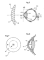
- the other lens 20 of the system illustrated in FIG. 1 is an intraocular lens to be implanted in the aphakic eye 100 in substitution for the natural crystalline lens, as illustrated by FIG. 1. In accordance with the definition Given in the introduction, it is therefore an opening lens.
- the intraocular lens 20 is implanted in the anterior chamber of the eye 100, that is to say in the part thereof which extends between its cornea 102 and its iris. 103.
- This mode of implantation is however not limiting: it will be possible to implant the lens in other locations according to the various known operating techniques, in particular in the posterior chamber or the capsular bag.
- the lens 20 forming an implant is equipped, at its periphery, in diametrically opposite positions, with two elastically deformable arms 23 in the general shape of "S", suitable for its support on the ciliary bodies of the eye 100, at the root of the iris 103.
- the lens 20 is conventionally made of synthetic material, for example of methyl methacrylate polymer.
- the opening lens 20 is more multifocal.
- multifocal means that the lens has a plurality of foci which differ according to the zone of the latter.
- the aperture lens 20 has a power addition defined as the difference of the maximum and minimum focal powers.
- the lens 20 is of the bifocal concentric type with two zones; but this choice is not limiting and other types of multifocal implants may be used, as we will see in more detail later.
- this intraocular lens 20 has an anterior face 21 and a posterior face 22.
- the anterior face 21 and the posterior face 22 are convex; but other configurations are possible, in particular that in which the anterior face 21 is convex and the posterior face 22 concave.
- multifocal intraocular lenses have, in its optically useful central part, several refractive or diffractive zones distinguished by their focal lengths. These zones of distinct powers thus create for each object several different images superimposed on the retina, one clearly the other blurred.
- the functioning of such a system relies on the neutralization capabilities that allow the brain to select the sharp image.
- the intraocular lens 20 is bifocal concentric. It has a central area 25 for near vision power Pu 20 / P and a peripheral annular area 26 for far vision power Pu 20 / L.
- the additions ⁇ Pu 10 and ⁇ Pu 20 of the two lenses 10 and 20 are dependent on one another and must satisfy certain criteria.
- the optical system formed by the combination of the two lenses 10 and 20 has an overall addition, defined as being the sum of the additions of the two lenses.
- This overall addition corresponds, to within 10%, to the addition prescribed to the wearer. It is, according to the invention, on the one hand limited and on the other hand distributed on both lenses 10 and 20.
- each of the two lenses 10 and 20 is greater than or equal to one quarter of the overall addition, which guarantees the equilibrium and the efficiency of the distribution: ⁇ Can 10 ⁇ ( ⁇ Can 10 + ⁇ Can 20 ) / 4 and ⁇ Can 20 ⁇ ( ⁇ Can 10 + ⁇ Can 20 ) / 4
- the distribution of addition between the two lenses can be parity.
- the spectacle lens 10 as the intraocular lens 20 the same addition of about 2 diopters.
- Figures 5 to 8 illustrate a second example of implementation of the invention. It is a visual equipment for a presbyopic patient. But the same equipment could also equip a patient who has lost all natural accommodation, such as an aphake.
- the equipment consists on the one hand of a pair of glasses with a lens arranged opposite each eye and secondly of a pair of contact lenses each affixed to an eye.
- Two optical systems according to the invention are thus formed, each consisting of the spectacle lens (field lens) and the contact lens (aperture lens) placed opposite the same eye.
- an eye 110 is recognized with its main components: cornea 112, the iris 113, bag 114 containing the lens 119, and, at the bottom of the eye, the retina 115 with the fovea 116 situated above it of the disc 117 opposite which points the optic nerve 118.
- Each optical system comprises, in combination on the axis 101 of the eye to be corrected 100, two lenses 30, 40.
- the lens 30 is mounted on the spectacle frame (not shown) and, disposed opposite and at a distance from the eye 100, is of the field lens type as defined in the introduction.
- the field lens 30 is additionally multifocal, according to the definition previously given. More specifically, the lens 10 belongs here to the first category of multifocal field lenses defined above. It is therefore a discontinuity lens power. But this choice is not limiting and we can use a progressive addition lens in combination with a contact lens.
- the power discontinuity field lenses are well known and it is not necessary to explain here the details of constitution and manufacture which have been the subject of numerous publications and commercializations. Suffice it to say that there are two main types of multifocal lenses with a power discontinuity which are equally suitable for the implementation of the present invention: cut lenses and fused glasses.
- the multiplicity of power for the same glass can indeed be obtained, either by a change of curvature of one of the two faces (multifocal discontinuous cut or molded), or by the inclusion of a refractive index material more high (merged multifocal).
- CT 28 ORMEX a change of curvature of one of the two faces
- CT 28 ORMA a refractive index material more high
- the lens 30 therefore consists of such a power discontinuity lens. It has a convex front face 31 which carries the power discontinuity and a concave rear face 32 which is spherical or toroidal and carries the prescription.
- Figure 6 there is shown in plan a finished lens whose contour, before trimming, is circular in shape and typically has a diameter of 60 to 80 mm.
- the x-axis X corresponds to the horizontal axis of the lens and the y-axis Y to the vertical axis.
- the vertical and horizontal correspond to the orientation of the lens during its use.
- the front face 31 of the lens 30 has two spherical zones of distinct centers and curvatures. There is thus a main zone 33 located in the upper part of the lens and used for far vision.
- the optical center of this zone 33 is here confused with the geometric center O of the lens, but can also be shifted by about 1 mm from the nasal side on the x-axis X.
- a zone 34 serving for near vision.
- This zone of greater curvature than the zone 32, locally gives the lens a higher spherical power.
- the optical center of this zone 34, noted C, is shifted to the nasal side by a few millimeters.
- Line 35 delimiting zone 34 has the shape of a 25 mm diameter circle portion and center C truncated in its upper part by a generally horizontal portion, which is here slightly curved as shown in FIG. vertex is located a few millimeters (in this case, 4.5 mm) below the X axis.
- the bifocal lens 30 is defined in particular by two main optical magnitudes: the addition and the nominal power.
- the nominal power is equal to the power of the far vision area Pu 30 / L.
- the other lens 40 of the system illustrated in FIG. 5 is a corneal contact lens to be affixed to the cornea 112 of the eye 110, as illustrated. According to the definition given in the introduction, it is therefore an opening lens.
- the lens 40 is a flexible lens conventionally made of hydrophilic synthetic material, for example: hydroxyethyl methacrylate, acrylmonomer, vinylpyrrolidone (N-vinyl 2-pyrrolidone), epoxy.
- the contact lens 40 is more multifocal.
- multifocal is understood to mean that the lens has a plurality of foci which differ according to the zone of interest thereof. It has a power addition defined as the difference of its maximum and minimum focal powers.
- multifocal contact lenses have, in its optically useful part, several refractive or diffractive zones distinguished by their focal lengths. These zones of distinct powers thus create for each object several different images superimposed on the retina, one clearly the other blurred.
- the functioning of such a system relies on the neutralization capabilities that allow the brain to select the sharp image.
- the lens 40 is of the progressive aspherical type; but this choice is not limiting, as we will see in more detail later.
- the contact lens 40 has an anterior face 41 and a posterior face 42.
- the anterior face 41 has a sphero-aspherical geometry, with a spherical central zone 43 for near vision surrounded by an annular zone with an aspherical profile 44 which generates the progression of power from the periphery to the center, for the intermediate and far vision. This power progression is continuous and monotonous.
- a peripheral zone 45 extends the lens for sitting and holding on the eye without exercising optical function.
- the central zone 43 has a diameter of 2 to 4 mm and the annular zone 43 has a diameter of 6 to 14 mm.
- the connection between the zones is continuous at least second order. It is understood that the dotted circles delimiting these three zones have been shown in Figure 7 for didactic purposes and have no visible physical consistency.
- the posterior face 42 is spherical or toric and is conventionally adapted to the prescription of the wearer.
- Pu 40 / P the power of the lens in the central zone for near vision 43 and Pu 20 / L the power for far vision, which corresponds to the minimum power of the lens in the annular aspheric zone for vision by far 44 and which is reached at the outer edge of this zone.
- the additions ⁇ Pu 30 and ⁇ Pu 40 of the two lenses 30 and 40 are dependent on one another and must satisfy certain criteria.
- the optical system formed by the combination of the two lenses 30 and 40 has an overall addition, defined as being the sum of the additions of the two lenses.
- This overall addition corresponds, to within 10%, to the addition prescribed to the wearer. It is, according to the invention, on the one hand limited and secondly distributed on both lenses 30 and 40.
- a non-aphakic eye suffering from a pronounced presbyopia it can advantageously be chosen close to 3 diopters.
- the distribution of addition between the two lenses can be parity.
- the spectacle lens 30 as the intraocular lens 40 the same addition of about 1.5 diopters.
- the multifocal field lens 30 can affect any known shape.
- the examples of Figures 1 and 2 for the progressive lens and Figures 5 and 6 for the discontinuous bifocal lens are not limiting.
- the multifocal opening lens can, whatever the origin of the disorder to be corrected, affect any known shape.
- FIGS. 3 and 4 for the intraocular lens and FIGS. 7 and 8 for the contact lens are not limiting. It is possible to use, for the implementation of the invention, any type of multifocal opening lens described in the state of the art. In this perspective, it is understood that the teaching provided for a contact lens may be transposed to use as an intraocular lens by simply adding to the lens means of its fixation in the eye.
- the aperture lens used in the system according to the invention may belong to any one of these categories.
- the first category includes lenses having a defined number of foci and having a plurality of discrete areas of distinct powers with one or more power discontinuities. These are typically bifocal or trifocal lenses in which the near, intermediate (possibly) and far vision zones are separated by discontinuity lines generating an image jump.
- a two-zone concentric bifocal aperture, contact or intraocular lens such as that described in US Pat. No. 3,422,000.
- bifocal opening of revolution in this case a contact lens, but the teaching is transposable to an intraocular lens
- US Pat. Nos. 3,227,000, 3,726,587 and 463,6049 describe the reverse configuration corresponding to the example of FIGS. 2 and 3 (for a contact lens), with a central zone for near vision and a peripheral annular zone for vision. from afar.
- the transition portions between the rings can be softened to have some refractive power for intermediate vision.
- a third power for the intermediate vision can be added to the alternation.
- the second category of multifocal opening lenses that can be used is that of progressive intraocular or aspherical contact lenses. These are lenses of revolution in which the power varies gradually according to a law of monotonous variation from the center to the periphery or vice versa.
- the aspherical curvature may be on the anterior or posterior side. Although the opposite configuration is conceivable, it is preferable to wear asphericity on the anterior surface, so that the near vision zone is in the center of the lens.
- Different geometries are possible, in particular: sphero-aspherical geometry, with a spherical central button extending peripherally by an aspheric profile which generates the progression (or disintegration) of power (as in the example of FIGS.
- the diffractive network is made in the posterior face to be stabilized by its immersion in tears and its depth is very low (of the order of 0.003 mm) to avoid a deleterious effect on the epithelium corneal.
- An example of such a lens is given in US-4162122.
Claims (10)
- Optisches akkommodatives Kompensationssystem, das kombiniert zwei Multifokallinsen, nämlich eine Öffnungslinse und eine Feldlinse aufweist.
- Optisches System nach Anspruch 1, bei dem die Öffnungslinse eine Stärkenhinzufügung aufweist, die als Unterschied der maximalen und minimalen Brennstärke definiert ist, und die Feldlinse eine Stärkenhinzufügung aufweist, die als der Unterschied der Brennstärken an den Referenzpunkten für das Weitsehvermögen und Nahsehvermögen definiert ist, wobei das System eine globale Hinzufügung aufweist, die als die Summe der Hinzufügungen der zwei Linsen definiert ist, die zwischen 2,5 und 4 Dioptrien liegt, und die Hinzufügung jeder Linse größer oder gleich dem Viertel der Gesamthinzufügung ist.
- Optisches System nach dem vorhergehenden Anspruch, bei dem das Hinzufügen jeder Linse größer oder gleich 40 % der Gesamthinzufügung ist.
- Optisches System nach einem der vorhergehenden Ansprüche, bei dem die Feldlinse zu einer der folgenden Kategorien gehört: mit allmählichem Hinzufügen, mit Stärkendiskontinuität.
- Optisches System nach einem der vorhergehenden Ansprüche, bei dem die Öffnungslinse zu einer der folgenden Kategorien gehört: konzentrisch, asphärisch progressiv, diffraktiv.
- Optisches System nach einem der Ansprüche 1 bis 3, bei dem die zwei Linsen progressive Linsen sind.
- Optisches System nach einem der vorhergehenden Ansprüche, bei dem, da das zu korrigierende Auge aphak ist, die Öffnungslinse eine intraokulare Linse ist, die in das Auge als Ersatz für die natürliche Augenlinse zu implantieren ist.
- Optisches System nach einem der Ansprüche 1 bis 6, bei dem die Öffnungslinse eine Hornhautkontaktlinse ist.
- Sehausstattung für einen Patienten, der mindestens ein aphakes Auge hat, die ein optisches System nach Anspruch 7 aufweist und einerseits aus einer Brille besteht, die eine Linse hat, die gegenüber dem betreffenden Auge angeordnet ist und die Feldlinse des Systems bildet, und andererseits aus der intraokularen Linse.
- Sehausstattung für einen weitsichtigen Patienten, die jedem Auge zugewiesen ein optisches System nach Anspruch 8 aufweist und einerseits aus einer Brille mit einer Linse besteht, die gegenüber jedem Auge angeordnet ist und die Feldlinse des diesem Auge zugewiesenen Systems ist, und andererseits aus einem Paar Kontaktlinsen, die jeweils auf ein Auge angelegt werden und die Öffnungslinsen des zu diesem Auge gehörenden Systems bilden.
Applications Claiming Priority (2)
| Application Number | Priority Date | Filing Date | Title |
|---|---|---|---|
| FR0310171A FR2859286B1 (fr) | 2003-08-26 | 2003-08-26 | Systeme optique de compensation accommodative |
| PCT/FR2004/002120 WO2005022241A1 (fr) | 2003-08-26 | 2004-08-11 | Systeme optique de compensation accommodative |
Publications (2)
| Publication Number | Publication Date |
|---|---|
| EP1660929A1 EP1660929A1 (de) | 2006-05-31 |
| EP1660929B1 true EP1660929B1 (de) | 2006-11-29 |
Family
ID=34130598
Family Applications (1)
| Application Number | Title | Priority Date | Filing Date |
|---|---|---|---|
| EP04786292A Not-in-force EP1660929B1 (de) | 2003-08-26 | 2004-08-11 | Optisches akkomodatives kompensationssystem |
Country Status (10)
| Country | Link |
|---|---|
| US (1) | US7338161B2 (de) |
| EP (1) | EP1660929B1 (de) |
| JP (1) | JP4511535B2 (de) |
| AT (1) | ATE347122T1 (de) |
| AU (1) | AU2004269510B2 (de) |
| CA (1) | CA2536953C (de) |
| DE (1) | DE602004003509T2 (de) |
| ES (1) | ES2277294T3 (de) |
| FR (1) | FR2859286B1 (de) |
| WO (1) | WO2005022241A1 (de) |
Families Citing this family (15)
| Publication number | Priority date | Publication date | Assignee | Title |
|---|---|---|---|---|
| CN101467092B (zh) * | 2006-06-08 | 2011-01-12 | 视力Crc有限公司 | 用于控制近视发展的装置 |
| US7753521B2 (en) * | 2008-03-31 | 2010-07-13 | Johnson & Johnson Vision Care, Inc. | Lenses for the correction of presbyopia and methods of designing the lenses |
| JP5657266B2 (ja) * | 2010-04-14 | 2015-01-21 | 株式会社メニコン | 不正乱視矯正用コンタクトレンズ |
| WO2013055212A1 (en) * | 2011-10-11 | 2013-04-18 | Akkolens International B.V. | Accommodating intraocular lens with optical correction surfaces |
| TWI588560B (zh) | 2012-04-05 | 2017-06-21 | 布萊恩荷登視覺協會 | 用於屈光不正之鏡片、裝置、方法及系統 |
| US9201250B2 (en) | 2012-10-17 | 2015-12-01 | Brien Holden Vision Institute | Lenses, devices, methods and systems for refractive error |
| CN104768499B (zh) | 2012-10-17 | 2017-06-23 | 华柏恩视觉研究中心 | 用于屈光不正的镜片、装置、方法和系统 |
| ES2472121B1 (es) * | 2012-12-27 | 2015-04-13 | Consejo Superior De Investigaciones Científicas (Csic) | Lente intraocular multifocal refractiva con calidad óptica optimizada en un rango de foco y procedimiento para obtenerla |
| US10299910B2 (en) | 2014-09-22 | 2019-05-28 | Kevin J. Cady | Intraocular pseudophakic contact lens with mechanism for securing by anterior leaflet of capsular wall and related system and method |
| US10159562B2 (en) | 2014-09-22 | 2018-12-25 | Kevin J. Cady | Intraocular pseudophakic contact lenses and related systems and methods |
| US11109957B2 (en) | 2014-09-22 | 2021-09-07 | Onpoint Vision, Inc. | Intraocular pseudophakic contact lens with mechanism for securing by anterior leaflet of capsular wall and related system and method |
| US11938018B2 (en) | 2014-09-22 | 2024-03-26 | Onpoint Vision, Inc. | Intraocular pseudophakic contact lens (IOPCL) for treating age-related macular degeneration (AMD) or other eye disorders |
| US10945832B2 (en) | 2014-09-22 | 2021-03-16 | Onpoint Vision, Inc. | Intraocular pseudophakic contact lens with mechanism for securing by anterior leaflet of capsular wall and related system and method |
| BR112020007723A2 (pt) * | 2017-12-28 | 2020-10-13 | Medicontur Orvostechnikai Kft. | lente oftalmática artificial trifocal e método para a sua produção |
| EP4157146A1 (de) | 2020-06-01 | 2023-04-05 | Icares Medicus, Inc. | Doppelseitige asphärische diffraktive multifokallinse, herstellung und verwendungen davon |
Family Cites Families (7)
| Publication number | Priority date | Publication date | Assignee | Title |
|---|---|---|---|---|
| US2164801A (en) * | 1936-10-22 | 1939-07-04 | Bausch & Lomb | Corrective lens system |
| US3027803A (en) * | 1959-06-29 | 1962-04-03 | Nat Eye Res Foundation | Spectacle lens-contact lens system |
| DE3332313A1 (de) * | 1983-09-07 | 1985-04-04 | Titmus Eurocon Kontaktlinsen GmbH, 8750 Aschaffenburg | Multifokale, insbesondere bifokale intraokulare kuenstliche augenlinse |
| US5030231A (en) * | 1988-01-05 | 1991-07-09 | Allergan, Inc. | Teledioptric lens system |
| JPH02217818A (ja) * | 1989-02-20 | 1990-08-30 | Nippon Contact Lens Kk | 老視用コンタクトレンズ |
| FR2699294B1 (fr) * | 1992-12-11 | 1995-02-10 | Essilor Int | Lentille ophtalmique multifocale progressive. |
| AU2003263080A1 (en) * | 2002-09-04 | 2004-03-29 | The Schepens Eye Research Institute, Inc. | Double bifocal intraocular lens-spectacle telescopic device |
-
2003
- 2003-08-26 FR FR0310171A patent/FR2859286B1/fr not_active Expired - Fee Related
-
2004
- 2004-08-11 WO PCT/FR2004/002120 patent/WO2005022241A1/fr active IP Right Grant
- 2004-08-11 AU AU2004269510A patent/AU2004269510B2/en not_active Ceased
- 2004-08-11 US US10/569,383 patent/US7338161B2/en active Active
- 2004-08-11 ES ES04786292T patent/ES2277294T3/es active Active
- 2004-08-11 EP EP04786292A patent/EP1660929B1/de not_active Not-in-force
- 2004-08-11 CA CA2536953A patent/CA2536953C/fr not_active Expired - Fee Related
- 2004-08-11 DE DE602004003509T patent/DE602004003509T2/de active Active
- 2004-08-11 AT AT04786292T patent/ATE347122T1/de not_active IP Right Cessation
- 2004-08-11 JP JP2006524386A patent/JP4511535B2/ja not_active Expired - Fee Related
Also Published As
| Publication number | Publication date |
|---|---|
| JP4511535B2 (ja) | 2010-07-28 |
| ATE347122T1 (de) | 2006-12-15 |
| CA2536953A1 (fr) | 2005-03-10 |
| CA2536953C (fr) | 2012-09-18 |
| AU2004269510B2 (en) | 2009-01-29 |
| JP2007503235A (ja) | 2007-02-22 |
| DE602004003509D1 (de) | 2007-01-11 |
| DE602004003509T2 (de) | 2007-10-04 |
| EP1660929A1 (de) | 2006-05-31 |
| FR2859286B1 (fr) | 2005-09-30 |
| AU2004269510A1 (en) | 2005-03-10 |
| ES2277294T3 (es) | 2007-07-01 |
| WO2005022241A1 (fr) | 2005-03-10 |
| US7338161B2 (en) | 2008-03-04 |
| FR2859286A1 (fr) | 2005-03-04 |
| US20070030444A1 (en) | 2007-02-08 |
Similar Documents
| Publication | Publication Date | Title |
|---|---|---|
| US10420639B2 (en) | Foldable intraocular lens and method of making | |
| US8137399B2 (en) | Implantable prismatic device, and related methods and systems | |
| KR102080980B1 (ko) | 확장된 피사계 심도 및 향상된 원거리 시력의 안과용 임플란트 | |
| EP1660929B1 (de) | Optisches akkomodatives kompensationssystem | |
| US20050125055A1 (en) | Foldable intraocular lens and method of making | |
| JP2013515284A (ja) | 単一微細構造のレンズ、システム及び方法 | |
| US20010033363A1 (en) | Pair of ophthalmic lenses, range of ophthalmic lenses and method for prescribing a pair of ophthalmic lenses | |
| JP6953423B2 (ja) | 被写界深度延長及び遠見視力向上を伴う眼科インプラント | |
| US11963868B2 (en) | Double-sided aspheric diffractive multifocal lens, manufacture, and uses thereof | |
| WO2012138426A2 (en) | An implantable ophthalmic device with multiple static apertures | |
| US20190076242A1 (en) | Methods of providing extended depth of field and/or enhanced distance visual acuity | |
| WO2010014767A1 (en) | Multifocal ophthalmic lens having reduced ghosting | |
| US20120033177A1 (en) | Aspheric, astigmatic, multi-focal contact lens with asymmetric point spread function | |
| FR2860706A1 (fr) | Systeme de grandissement d'image retinienne | |
| NL2026791B1 (nl) | Werkwijze voor het vervaardigen van lenzen voor patiënten met keratoconus | |
| WO2023161591A1 (fr) | Lentille intraoculaire a optique par dilution | |
| FR3098707A1 (fr) | Implant oculaire diffractif à vision proche élargie | |
| WO2023137462A1 (en) | Aspheric phase-ring structured lens designs, manufacture, and uses thereof |
Legal Events
| Date | Code | Title | Description |
|---|---|---|---|
| PUAI | Public reference made under article 153(3) epc to a published international application that has entered the european phase |
Free format text: ORIGINAL CODE: 0009012 |
|
| 17P | Request for examination filed |
Effective date: 20060207 |
|
| AK | Designated contracting states |
Kind code of ref document: A1 Designated state(s): AT BE BG CH CY CZ DE DK EE ES FI FR GB GR HU IE IT LI LU MC NL PL PT RO SE SI SK TR |
|
| GRAP | Despatch of communication of intention to grant a patent |
Free format text: ORIGINAL CODE: EPIDOSNIGR1 |
|
| GRAS | Grant fee paid |
Free format text: ORIGINAL CODE: EPIDOSNIGR3 |
|
| GRAA | (expected) grant |
Free format text: ORIGINAL CODE: 0009210 |
|
| DAX | Request for extension of the european patent (deleted) | ||
| AK | Designated contracting states |
Kind code of ref document: B1 Designated state(s): AT BE BG CH CY CZ DE DK EE ES FI FR GB GR HU IE IT LI LU MC NL PL PT RO SE SI SK TR |
|
| PG25 | Lapsed in a contracting state [announced via postgrant information from national office to epo] |
Ref country code: IE Free format text: LAPSE BECAUSE OF FAILURE TO SUBMIT A TRANSLATION OF THE DESCRIPTION OR TO PAY THE FEE WITHIN THE PRESCRIBED TIME-LIMIT Effective date: 20061129 Ref country code: FI Free format text: LAPSE BECAUSE OF FAILURE TO SUBMIT A TRANSLATION OF THE DESCRIPTION OR TO PAY THE FEE WITHIN THE PRESCRIBED TIME-LIMIT Effective date: 20061129 Ref country code: PL Free format text: LAPSE BECAUSE OF FAILURE TO SUBMIT A TRANSLATION OF THE DESCRIPTION OR TO PAY THE FEE WITHIN THE PRESCRIBED TIME-LIMIT Effective date: 20061129 Ref country code: RO Free format text: LAPSE BECAUSE OF FAILURE TO SUBMIT A TRANSLATION OF THE DESCRIPTION OR TO PAY THE FEE WITHIN THE PRESCRIBED TIME-LIMIT Effective date: 20061129 Ref country code: CZ Free format text: LAPSE BECAUSE OF FAILURE TO SUBMIT A TRANSLATION OF THE DESCRIPTION OR TO PAY THE FEE WITHIN THE PRESCRIBED TIME-LIMIT Effective date: 20061129 Ref country code: SI Free format text: LAPSE BECAUSE OF FAILURE TO SUBMIT A TRANSLATION OF THE DESCRIPTION OR TO PAY THE FEE WITHIN THE PRESCRIBED TIME-LIMIT Effective date: 20061129 Ref country code: SK Free format text: LAPSE BECAUSE OF FAILURE TO SUBMIT A TRANSLATION OF THE DESCRIPTION OR TO PAY THE FEE WITHIN THE PRESCRIBED TIME-LIMIT Effective date: 20061129 Ref country code: NL Free format text: LAPSE BECAUSE OF FAILURE TO SUBMIT A TRANSLATION OF THE DESCRIPTION OR TO PAY THE FEE WITHIN THE PRESCRIBED TIME-LIMIT Effective date: 20061129 Ref country code: AT Free format text: LAPSE BECAUSE OF FAILURE TO SUBMIT A TRANSLATION OF THE DESCRIPTION OR TO PAY THE FEE WITHIN THE PRESCRIBED TIME-LIMIT Effective date: 20061129 |
|
| REG | Reference to a national code |
Ref country code: GB Ref legal event code: FG4D Free format text: NOT ENGLISH |
|
| REG | Reference to a national code |
Ref country code: CH Ref legal event code: EP |
|
| GBT | Gb: translation of ep patent filed (gb section 77(6)(a)/1977) |
Effective date: 20061220 |
|
| REG | Reference to a national code |
Ref country code: IE Ref legal event code: FG4D Free format text: LANGUAGE OF EP DOCUMENT: FRENCH |
|
| REF | Corresponds to: |
Ref document number: 602004003509 Country of ref document: DE Date of ref document: 20070111 Kind code of ref document: P |
|
| PG25 | Lapsed in a contracting state [announced via postgrant information from national office to epo] |
Ref country code: SE Free format text: LAPSE BECAUSE OF FAILURE TO SUBMIT A TRANSLATION OF THE DESCRIPTION OR TO PAY THE FEE WITHIN THE PRESCRIBED TIME-LIMIT Effective date: 20070228 Ref country code: BG Free format text: LAPSE BECAUSE OF FAILURE TO SUBMIT A TRANSLATION OF THE DESCRIPTION OR TO PAY THE FEE WITHIN THE PRESCRIBED TIME-LIMIT Effective date: 20070228 Ref country code: DK Free format text: LAPSE BECAUSE OF FAILURE TO SUBMIT A TRANSLATION OF THE DESCRIPTION OR TO PAY THE FEE WITHIN THE PRESCRIBED TIME-LIMIT Effective date: 20070228 |
|
| PG25 | Lapsed in a contracting state [announced via postgrant information from national office to epo] |
Ref country code: PT Free format text: LAPSE BECAUSE OF FAILURE TO SUBMIT A TRANSLATION OF THE DESCRIPTION OR TO PAY THE FEE WITHIN THE PRESCRIBED TIME-LIMIT Effective date: 20070430 |
|
| NLV1 | Nl: lapsed or annulled due to failure to fulfill the requirements of art. 29p and 29m of the patents act | ||
| REG | Reference to a national code |
Ref country code: IE Ref legal event code: FD4D |
|
| REG | Reference to a national code |
Ref country code: ES Ref legal event code: FG2A Ref document number: 2277294 Country of ref document: ES Kind code of ref document: T3 |
|
| PLBE | No opposition filed within time limit |
Free format text: ORIGINAL CODE: 0009261 |
|
| STAA | Information on the status of an ep patent application or granted ep patent |
Free format text: STATUS: NO OPPOSITION FILED WITHIN TIME LIMIT |
|
| 26N | No opposition filed |
Effective date: 20070830 |
|
| BERE | Be: lapsed |
Owner name: ESSILOR INTERNATIONAL (COMPAGNIE GENERALE D'OPTIQ Effective date: 20070831 |
|
| PG25 | Lapsed in a contracting state [announced via postgrant information from national office to epo] |
Ref country code: GR Free format text: LAPSE BECAUSE OF FAILURE TO SUBMIT A TRANSLATION OF THE DESCRIPTION OR TO PAY THE FEE WITHIN THE PRESCRIBED TIME-LIMIT Effective date: 20070301 Ref country code: MC Free format text: LAPSE BECAUSE OF NON-PAYMENT OF DUE FEES Effective date: 20070831 |
|
| PG25 | Lapsed in a contracting state [announced via postgrant information from national office to epo] |
Ref country code: BE Free format text: LAPSE BECAUSE OF NON-PAYMENT OF DUE FEES Effective date: 20070831 |
|
| PG25 | Lapsed in a contracting state [announced via postgrant information from national office to epo] |
Ref country code: EE Free format text: LAPSE BECAUSE OF FAILURE TO SUBMIT A TRANSLATION OF THE DESCRIPTION OR TO PAY THE FEE WITHIN THE PRESCRIBED TIME-LIMIT Effective date: 20061129 |
|
| REG | Reference to a national code |
Ref country code: CH Ref legal event code: PL |
|
| PG25 | Lapsed in a contracting state [announced via postgrant information from national office to epo] |
Ref country code: CH Free format text: LAPSE BECAUSE OF NON-PAYMENT OF DUE FEES Effective date: 20080831 Ref country code: LI Free format text: LAPSE BECAUSE OF NON-PAYMENT OF DUE FEES Effective date: 20080831 |
|
| PG25 | Lapsed in a contracting state [announced via postgrant information from national office to epo] |
Ref country code: LU Free format text: LAPSE BECAUSE OF NON-PAYMENT OF DUE FEES Effective date: 20070811 Ref country code: CY Free format text: LAPSE BECAUSE OF FAILURE TO SUBMIT A TRANSLATION OF THE DESCRIPTION OR TO PAY THE FEE WITHIN THE PRESCRIBED TIME-LIMIT Effective date: 20061129 |
|
| PG25 | Lapsed in a contracting state [announced via postgrant information from national office to epo] |
Ref country code: TR Free format text: LAPSE BECAUSE OF FAILURE TO SUBMIT A TRANSLATION OF THE DESCRIPTION OR TO PAY THE FEE WITHIN THE PRESCRIBED TIME-LIMIT Effective date: 20061129 Ref country code: HU Free format text: LAPSE BECAUSE OF FAILURE TO SUBMIT A TRANSLATION OF THE DESCRIPTION OR TO PAY THE FEE WITHIN THE PRESCRIBED TIME-LIMIT Effective date: 20070530 |
|
| REG | Reference to a national code |
Ref country code: FR Ref legal event code: PLFP Year of fee payment: 13 |
|
| REG | Reference to a national code |
Ref country code: FR Ref legal event code: PLFP Year of fee payment: 14 |
|
| REG | Reference to a national code |
Ref country code: DE Ref legal event code: R082 Ref document number: 602004003509 Country of ref document: DE Representative=s name: 24IP LAW GROUP SONNENBERG FORTMANN, DE Ref country code: DE Ref legal event code: R081 Ref document number: 602004003509 Country of ref document: DE Owner name: ESSILOR INTERNATIONAL, FR Free format text: FORMER OWNER: ESSILOR INTERNATIONAL (COMPAGNIE GENERALE D'OPTIQUE), CHARENTON-LE-PONT, FR |
|
| REG | Reference to a national code |
Ref country code: ES Ref legal event code: PC2A Effective date: 20180521 Ref country code: ES Ref legal event code: PC2A Owner name: ESSILOR INTERNATIONAL Effective date: 20180521 |
|
| REG | Reference to a national code |
Ref country code: GB Ref legal event code: 732E Free format text: REGISTERED BETWEEN 20180517 AND 20180523 |
|
| REG | Reference to a national code |
Ref country code: FR Ref legal event code: TP Owner name: ESSILOR INTERNATIONAL, FR Effective date: 20180601 |
|
| REG | Reference to a national code |
Ref country code: FR Ref legal event code: PLFP Year of fee payment: 15 |
|
| PGFP | Annual fee paid to national office [announced via postgrant information from national office to epo] |
Ref country code: DE Payment date: 20190828 Year of fee payment: 16 Ref country code: ES Payment date: 20190902 Year of fee payment: 16 Ref country code: FR Payment date: 20190826 Year of fee payment: 16 Ref country code: IT Payment date: 20190826 Year of fee payment: 16 |
|
| PGFP | Annual fee paid to national office [announced via postgrant information from national office to epo] |
Ref country code: GB Payment date: 20190827 Year of fee payment: 16 |
|
| REG | Reference to a national code |
Ref country code: DE Ref legal event code: R119 Ref document number: 602004003509 Country of ref document: DE |
|
| GBPC | Gb: european patent ceased through non-payment of renewal fee |
Effective date: 20200811 |
|
| PG25 | Lapsed in a contracting state [announced via postgrant information from national office to epo] |
Ref country code: FR Free format text: LAPSE BECAUSE OF NON-PAYMENT OF DUE FEES Effective date: 20200831 Ref country code: DE Free format text: LAPSE BECAUSE OF NON-PAYMENT OF DUE FEES Effective date: 20210302 |
|
| PG25 | Lapsed in a contracting state [announced via postgrant information from national office to epo] |
Ref country code: GB Free format text: LAPSE BECAUSE OF NON-PAYMENT OF DUE FEES Effective date: 20200811 |
|
| REG | Reference to a national code |
Ref country code: ES Ref legal event code: FD2A Effective date: 20220103 |
|
| PG25 | Lapsed in a contracting state [announced via postgrant information from national office to epo] |
Ref country code: ES Free format text: LAPSE BECAUSE OF NON-PAYMENT OF DUE FEES Effective date: 20200812 |
|
| PG25 | Lapsed in a contracting state [announced via postgrant information from national office to epo] |
Ref country code: IT Free format text: LAPSE BECAUSE OF NON-PAYMENT OF DUE FEES Effective date: 20200811 |