EP1660903B1 - Method for receiver autonomous integrity monitoring and fault detection and elimination - Google Patents
Method for receiver autonomous integrity monitoring and fault detection and elimination Download PDFInfo
- Publication number
- EP1660903B1 EP1660903B1 EP04786560A EP04786560A EP1660903B1 EP 1660903 B1 EP1660903 B1 EP 1660903B1 EP 04786560 A EP04786560 A EP 04786560A EP 04786560 A EP04786560 A EP 04786560A EP 1660903 B1 EP1660903 B1 EP 1660903B1
- Authority
- EP
- European Patent Office
- Prior art keywords
- measurements
- gps
- measurement
- correlation value
- computing
- Prior art date
- Legal status (The legal status is an assumption and is not a legal conclusion. Google has not performed a legal analysis and makes no representation as to the accuracy of the status listed.)
- Expired - Lifetime
Links
- 238000000034 method Methods 0.000 title claims abstract description 77
- 238000012544 monitoring process Methods 0.000 title description 7
- 238000001514 detection method Methods 0.000 title description 4
- 230000008030 elimination Effects 0.000 title description 3
- 238000003379 elimination reaction Methods 0.000 title description 3
- 238000005259 measurement Methods 0.000 claims abstract description 218
- 239000011159 matrix material Substances 0.000 claims description 30
- 238000012360 testing method Methods 0.000 claims description 19
- 238000012937 correction Methods 0.000 claims description 14
- 230000035945 sensitivity Effects 0.000 claims description 13
- 230000008859 change Effects 0.000 claims description 7
- 230000008569 process Effects 0.000 claims description 7
- 238000012545 processing Methods 0.000 claims description 2
- 230000004044 response Effects 0.000 abstract description 3
- 239000013598 vector Substances 0.000 description 28
- 230000000875 corresponding effect Effects 0.000 description 20
- 238000004891 communication Methods 0.000 description 4
- 230000002596 correlated effect Effects 0.000 description 3
- 230000008901 benefit Effects 0.000 description 1
- 230000015556 catabolic process Effects 0.000 description 1
- 238000006731 degradation reaction Methods 0.000 description 1
- 238000010586 diagram Methods 0.000 description 1
- 230000000694 effects Effects 0.000 description 1
- 238000004870 electrical engineering Methods 0.000 description 1
- 230000007246 mechanism Effects 0.000 description 1
- 238000010606 normalization Methods 0.000 description 1
- 238000000926 separation method Methods 0.000 description 1
- 230000002123 temporal effect Effects 0.000 description 1
- 238000012795 verification Methods 0.000 description 1
Images


Classifications
-
- G—PHYSICS
- G01—MEASURING; TESTING
- G01S—RADIO DIRECTION-FINDING; RADIO NAVIGATION; DETERMINING DISTANCE OR VELOCITY BY USE OF RADIO WAVES; LOCATING OR PRESENCE-DETECTING BY USE OF THE REFLECTION OR RERADIATION OF RADIO WAVES; ANALOGOUS ARRANGEMENTS USING OTHER WAVES
- G01S19/00—Satellite radio beacon positioning systems; Determining position, velocity or attitude using signals transmitted by such systems
- G01S19/01—Satellite radio beacon positioning systems transmitting time-stamped messages, e.g. GPS [Global Positioning System], GLONASS [Global Orbiting Navigation Satellite System] or GALILEO
- G01S19/13—Receivers
- G01S19/20—Integrity monitoring, fault detection or fault isolation of space segment
Definitions
- the present invention relates generally to Fault Detection and Elimination (FDE) in a discrete-time controlled process, and particularly to methods for Receiver Autonomous Integrity Monitoring (RAIM) in global positioning systems (GPS).
- FDE Fault Detection and Elimination
- RAIM Receiver Autonomous Integrity Monitoring
- GPS uses satellites in space to locate objects on earth. With GPS, signals from the satellites arrive at a GPS receiver and are used to determine the position of the GPS receiver.
- the two types of GPS measurements are pseudorange, and integrated carrier phase for two carrier signals, L1 and L2, with frequencies of 1.5754 GHz and 1.2276 GHz, or wavelengths of 0.1903 m and 0.2442 m, respectively.
- the pseudorange measurement (or code measurement) is a basic GPS observable that all types of GPS receivers can make. It utilizes the C/A or P codes modulated onto the carrier signals.
- the measurement records the apparent time taken for the relevant code to travel from the satellite to the receiver, i.e., the time the signal arrives at the receiver according to the receiver clock minus the time the signal left the satellite according to the satellite clock.
- the carrier phase measurement is obtained by integrating a reconstructed carrier of the signal as it arrives at the receiver.
- the carrier phase measurement is also a measure of a transit time difference as determined by the time the signal left the satellite according to the satellite clock and the time it arrives at the receiver according to the receiver clock.
- the transit time difference may be in error by multiple carrier cycles, i.e., there is a whole-cycle ambiguity in the carrier phase measurement.
- the range or distance between a GPS receiver and each of a multitude of satellites is calculated by multiplying a signal's travel time by the speed of light.
- These ranges are usually referred to as pseudoranges (false ranges) because the receiver clock generally has a significant time error which causes a common bias in the measured range.
- This common bias from receiver clock error is solved for along with the position coordinates of the receiver as part of the normal navigation computation.
- Various other factors can also lead to errors or noise in the calculated range, including ephemeris error, satellite clock timing error, atmospheric effects, receiver noise and multipath error.
- Differential GPS (DGPS) operations typically involve a base reference GPS receiver, a user GPS receiver, and a communication mechanism between the user and reference receivers.
- the reference receiver is placed at a known location and the known position is used to generate corrections associated with some or all of the above error factors.
- the corrections are supplied to the user receiver and the user receiver then uses the corrections to appropriately correct its computed position.
- the corrections can be in the form of corrections to the reference receiver position determined at the reference site or in the form of corrections to the specific GPS satellite clock and/or orbit. Corrections to the reference receiver position are not as flexible as GPS satellite clock or orbit corrections because, for optimum accuracy, they require that the same satellites be observed by the user receiver and the reference receiver.
- DGPS Differential GPS
- WADGPS wide area DGPS
- the WADGPS includes a network of multiple reference stations in communication with a computational center or hub. Error corrections are computed at the hub based upon the known locations of the reference stations and the measurements taken by them. The computed error corrections are then transmitted to users via a communication link such as satellite, phone, or radio.
- a communication link such as satellite, phone, or radio.
- a user with a GPS receiver may use different modes of navigation, i.e., standalone GPS, DGPS, WADGPS, carrier-phase DGPS, etc. Whichever of the navigation modes is used, there is always the possibility that the range with respect to a satellite are computed based on a faulty measurement, such as a measurement with respect to a failed satellite. When this range is used in determining the position of the user, an erroneous or wrong position would result. Thus, a faulty measurement can cause serious degradation to the reliability and integrity of the GPS system. Therefore, various integrity monitoring techniques have been developed for fault detection and elimination (FDE) in GPS systems. Receiver autonomous integrity monitoring (RAIM) is the name coined by the FAA for methods of integrity monitoring in GPS using redundant GPS satellite measurements.
- RAIM Receiver autonomous integrity monitoring
- a method for detecting and identifying a faulty measurement among a plurality of GPS measurements, obtained by a GPS receiver with respect to a plurality of satellites in view of the GPS receiver determines whether the plurality of GPS measurements include a faulty measurement.
- the method identifies a satellite contributing the faulty measurement by computing a correlation value associated with each of the plurality of satellites, and selecting a satellite associated with a highest correlation value as the satellite contributing the faulty measurement.
- the satellite associated with the highest correlation value is selected when the highest correlation value exceeds a predetermined threshold value and the predetermined threshold value is sufficiently larger than a second highest correlation value. In an alternative embodiment the satellite associated with the highest correlation value is selected when the difference between the highest correlation value and a second highest correlation value exceeds a predetermined threshold.
- whether the GPS measurements include a faulty measurement is determined by computing test statistic using post-fix residuals corresponding to the plurality of GPS measurements, and comparing test statistic with a threshold residual value, which is chosen based on a navigation mode used by the GPS receiver. If the test statistic exceeds the threshold residual value, a faulty measurement is detected.
- the correlation value associated with a satellite is the absolute value of a correlation coefficient associated with the satellite.
- the correlation coefficient is computed based on a residual sensitivity matrix corresponding to the plurality of satellites and a residual vector including the post-fix residuals corresponding to the plurality of GPS measurements.
- the size of the error in the faulty GPS measurement is determined based on a residual sensitivity matrix corresponding to the plurality of satellites and the root mean square residual.
- Figure 1 is a block diagram of a computer system that can be used to carry out a method for detecting and identifying a faulty GPS measurement or a satellite contributing to the faulty GPS measurement.
- Figure 2 is a flowchart illustrating the method for detecting and identifying a faulty GPS measurement or a satellite contributing to the faulty GPS measurement.
- Figure 3 is a flowchart illustrating a method for determining whether a plurality of GPS measurements include a faulty GPS measurement.
- Figure 4 is a flowchart illustrating a method for identifying a faulty GPS measurement among a plurality of GPS measurements.
- Figure 5A is a flowchart illustrating a method for identifying a satellite with a highest correlation value as the satellite contributing to the faulty GPS measurement.
- Figure 5B is a flowchart illustrating another method for identifying a satellite with a highest correlation value as the satellite contributing to the faulty GPS measurement.
- Figure 6 is a flowchart illustrating a method for verifying that the satellite contributing to the faulty measurement has been identified correctly.
- FIG. 1 illustrates a computer system 100 that can be used to carry out the method for detecting and identifying a faulty GPS measurement among a plurality of GPS measurements.
- Each of the plurality of GPS measurements is taken by a GPS receiver 122 based on signals from one of a plurality of satellites 110-1, 110-2, ..., 110-n, where n is the number of satellites in view of the GPS receiver 122.
- the plurality of satellites, or any one or more of them, are sometimes referred to hereafter in this document as satellite(s) 110.
- the GPS receiver 122 and the computer system 100 are integrated into a single device, within a single housing, such as a portable, handheld or even wearable position tracking device, or a vehicle-mounted or otherwise mobile positioning and/or navigation system. In other embodiments, the GPS receiver 122 and the computer system 100 are not integrated into a single device.
- the computer system 100 includes a central processing unit (CPU) 126, memory 128, an input port 134 and an output port 136, and (optionally) a user interface 138, coupled to each other by one or more communication buses 129.
- the memory 128 may include high-speed random access memory and may include nonvolatile mass storage, such as one or more magnetic disk storage devices.
- the memory 128 preferably stores an operating system 131, a database 133, and GPS application procedures 135.
- the GPS application procedures may include procedures 137 for implementing the method for detecting and identifying the faulty GPS measurement, as described in more detail below.
- the operating system 131 and application programs and procedures 135 and 137 stored in memory 128 are for execution by the CPU 126 of the computer system 124.
- the memory 128 preferably also stores data structures used during execution of the GPS application procedures 135 and 137, including GPS pseudorange and/or carrier-phase measurements 139, as well as other data structures discussed in this document.
- the input port 134 is for receiving data from the GPS receiver 122, and output port 136 is used for outputting data and/or calculation results. Data and calculation results may also be shown on a display device of the user interface 138.
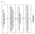
- FIG. 2 illustrates a method 200 for detecting and identifying a faulty GPS measurement among a plurality of GPS measurements obtained by the GPS receiver 122 with respect to the plurality of satellites 110.
- method 200 includes step 210 for determining whether the plurality of GPS measurements include a faulty measurement.
- method 200 further includes step 220 in which the faulty measurement is isolated or identified among the plurality of GPS measurements, or the satellite contributing to the faulty measurement is isolated or identified among the plurality of satellites.
- method 200 may include an optional step 230 in which a size of an error in the faulty measurement is determined, and an optional step 240 for verifying that the correct identification has been made.
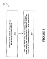
- FIG. 3 illustrates an embodiment of a method 300 for determining whether the GPS measurements include a faulty measurement in step 210.
- method 300 includes step 310 in which post-fix residuals corresponding to the plurality of GPS measurements are computed and step 320 in which a test statistics is formed using the post-fix residuals and is compared with a threshold to determine whether the plurality of GPS measurements include a faulty measurement.
- a residual of a GPS measurement represents a disagreement between the GPS measurement and a prediction or expected value of the GPS measurement. Before the position and clock bias of the GPS receiver are adjusted, the residuals are often referred to as pre-fix residuals or measurement innovations.
- a measurement innovation can be computed based on the difference between a GPS measurement and a theoretical prediction of the GPS measurement.
- a measurement innovation corresponding to a GPS measurement can be computed as the difference between the GPS measurement and an expected value of the GPS measurement computed from an initial estimated state of the GPS receiver, as discussed in the following.
- x is a state vector of the discrete-time controlled process and, in the case of GPS, it includes corrections to the position and clock bias of the GPS receiver
- H is a measurement sensitivity matrix including direction cosines of the state vector or unit vectors from the GPS receiver to each of the n satellites
- z is a measurement innovation vector including measurement innovations corresponding to the plurality of GPS measurements
- n is a measurement noise vector.
- the state vector may include an unknown ambiguity factor.
- the post-fix residuals are usually obtained in a two-step process.
- ⁇ is a residual vector including as its elements post-fix residuals corresponding to the plurality of GPS measurements
- each column (or row) of the S matrix includes residuals corresponding to a unit change in the measurement innovation of one of the plurality of satellites while the measurement innovations of the other ones of the plurality of satellites are kept unchanged.
- the post-fix residuals in the residual vector ⁇ can be computed according to Equation (5) in step 310.
- method 300 further includes step 320 in which the post-fix residuals or the root mean square residual are used to form a test statistic, which is then compared with a fault threshold to determine whether the plurality of GPS measurements include a faulty measurement.
- the fault threshold value is selected to correspond to the navigation mode used by the GPS receiver 122.
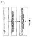
- FIG. 4 illustrates an embodiment of a method 400 for identifying the faulty measurement or a satellite contributing the faulty measurement in step 220 of method 200.
- method 400 includes step 410 in which a correlation value associated with each of the plurality of measurements or with each of the plurality of satellites is computed, and step 420 in which a satellite associated with a highest correlation value among the plurality of satellites 110 is identified as the satellite contributing the faulty measurement, or the GPS measurement with respect to the satellite associated with the highest correlation value is identified as the faulty measurement.
- the correlation value associated with each one of the plurality of satellites is computed based on a correlation coefficient associated with the satellite or with the one of the plurality of GPS measurements with respect to the satellite.
- s j the correlation coefficient associated with the j th satellite
- ⁇ i the i th element of the residual vector ⁇
- s i j the element in the i th row and j th column of the S matrix
- is the norm value of the residual vector ⁇
- s j represents the j th column of the S matrix
- the summation is over all elements of ⁇ or of the j th column of the S matrix.
- is equal to the square root of the diagonal element, s j j .
- the correlation value associated with a satellite is equal to the absolute value of the correlation coefficient associated with the satellite.
- the correlation coefficient associated with every satellite should be about one (or minus one). This is because the degree of freedom is only one (one more satellite than the number of unknowns in the state vector). With only five measurements corresponding to the five satellites, each column in the S matrix is perfectly correlated with the residual vector, except that the length of the columns are different. In other words, the large root mean square residual, which indicated a fault in step 210 of method 200, could be caused by a faulty measurement from any one of the satellites. Moreover, even when the number of satellites is greater than 5, a similar phenomenon can occur with a degenerate geometry. Such a degenerate geometry is indicated if more than one satellite are associated with correlation coefficients close to one or minus one.
- Method 500A or 500B can be used in step 420.
- Method 500A includes step 510A in which the highest correlation value is identified among the correlation values associated with the plurality of satellites.
- Method 500A further includes step 520A for determining that the highest correlation value exceed a predetermined threshold value and step 530A for determining that the predetermined threshold value is sufficiently larger than a second highest correlation value among the correlation values associated with the plurality of satellites.
- method 500B is used, which includes step 510B in which the highest and the second highest correlation values are identified, step 520B in which the difference between the highest and second highest correlation values are computed, and step 530B for determining that the difference exceeds a predetermined minimum difference value.
- method 200 may further include step 230 in which the size of any error in the faulty measurement (or the size of the fault) is estimated.
- Estimating the size of the fault is sometimes useful, especially when method 200 is used to identify a faulty measurement in a Real-Time Kinematic (RTK) navigation mode. Since RTK navigations usually involve carrier phase measurements and thus resolutions of whole-cycle ambiguities, a measurement fault can be the result of a cycle slip in a tracking loop or an improper determination of the whole-cycle ambiguity. When this is the case, the size of the fault will be a multiple of the carrier wavelength.
- method 200 may further include step 240 for verifying that there is only one faulty measurement among the plurality of GPS measurements and that the identification of the satellite contributing the faulty measurement is correctly made.
- FIG. 6 illustrates a method 600 for performing the verification in step 240.
- Method 600 further includes step 620 in which the test statistic is recalculated according to Equation (11), (12), or (12a) after the adjusted residual vector ⁇ ' is used to replace the residual vector ⁇ in the equation. If the fault identification has been made correctly, the recalculated test statistic should now pass the threshold test for the test statistic, indicating that the fault has been removed. Thus, method 600 further includes step 630 in which the recalculated test statistic is compared with the fault threshold to verify that there is only one faulty measurement among the plurality of GPS measurements and the identification of the satellite contributing the faulty measurement is correctly made.
- the above described method for identifying a faulty GPS measurement is computationally efficient because it works entirely in the measurement domain. When there are more than five satellites being tracked, the method can be used to dramatically improve the reliability of positioning and navigation using GPS, with only a small cost in additional computational complexity.
Landscapes
- Engineering & Computer Science (AREA)
- Radar, Positioning & Navigation (AREA)
- Remote Sensing (AREA)
- Computer Security & Cryptography (AREA)
- Computer Networks & Wireless Communication (AREA)
- Physics & Mathematics (AREA)
- General Physics & Mathematics (AREA)
- Position Fixing By Use Of Radio Waves (AREA)
- Monitoring And Testing Of Transmission In General (AREA)
- Communication Control (AREA)
Applications Claiming Priority (2)
| Application Number | Priority Date | Filing Date | Title |
|---|---|---|---|
| US10/656,956 US6864836B1 (en) | 2003-09-05 | 2003-09-05 | Method for receiver autonomous integrity monitoring and fault detection and elimination |
| PCT/US2004/027344 WO2005027283A2 (en) | 2003-09-05 | 2004-08-19 | Method for receiver autonomous integrity monitoring and fault detection and elimination |
Publications (2)
| Publication Number | Publication Date |
|---|---|
| EP1660903A2 EP1660903A2 (en) | 2006-05-31 |
| EP1660903B1 true EP1660903B1 (en) | 2007-10-17 |
Family
ID=34218150
Family Applications (1)
| Application Number | Title | Priority Date | Filing Date |
|---|---|---|---|
| EP04786560A Expired - Lifetime EP1660903B1 (en) | 2003-09-05 | 2004-08-19 | Method for receiver autonomous integrity monitoring and fault detection and elimination |
Country Status (11)
Families Citing this family (54)
| Publication number | Priority date | Publication date | Assignee | Title |
|---|---|---|---|---|
| US20060047413A1 (en) * | 2003-12-02 | 2006-03-02 | Lopez Nestor Z | GNSS navigation solution integrity in non-controlled environments |
| US8131463B2 (en) * | 2003-12-02 | 2012-03-06 | Gmv Aerospace And Defence, S.A. | GNSS navigation solution integrity in non-controlled environments |
| US7212155B2 (en) * | 2004-05-07 | 2007-05-01 | Navcom Technology, Inc. | GPS navigation using successive differences of carrier-phase measurements |
| JP4548604B2 (ja) * | 2005-06-14 | 2010-09-22 | 三菱自動車工業株式会社 | 車車間通信システム |
| US7501981B2 (en) * | 2005-11-18 | 2009-03-10 | Texas Instruments Incorporated | Methods and apparatus to detect and correct integrity failures in satellite positioning system receivers |
| US7286083B2 (en) * | 2005-12-15 | 2007-10-23 | Motorola, Inc. | Method and apparatus for improving fault detection and exclusion systems |
| US7733268B2 (en) | 2006-05-16 | 2010-06-08 | Andrew Corporation | Method and apparatus for determining the geographic location of a device |
| FR2905006B1 (fr) * | 2006-08-21 | 2008-10-17 | Airbus France Sas | Procede de surveillance de l'integrite d'une position avion calculee a bord |
| US7436354B2 (en) * | 2006-09-07 | 2008-10-14 | The Mitre Corporation | Methods and systems for mobile navigational applications using global navigation satellite systems |
| JP2008281552A (ja) * | 2007-04-09 | 2008-11-20 | Seiko Epson Corp | 初回測位出力位置演算決定方法、プログラム、記憶媒体、測位装置及び電子機器 |
| US7956802B1 (en) * | 2007-05-21 | 2011-06-07 | Rockwell Collins, Inc. | Integrity-optimized receiver autonomous integrity monitoring (RAIM) for vertical integrity monitoring |
| FR2918470B1 (fr) * | 2007-07-06 | 2009-09-18 | Thales Sa | Procede d'amelioration de l'integrite et de la securite d'un systeme avionique |
| US7800533B2 (en) * | 2008-11-24 | 2010-09-21 | Andrew, Llc | System and method for determining falsified geographic location of a mobile device |
| US20130138338A1 (en) * | 2011-11-30 | 2013-05-30 | Honeywell International Inc. | Graphical presentation of receiver autonomous integrity monitoring outage regions on an aircraft display |
| US9547086B2 (en) | 2013-03-26 | 2017-01-17 | Honeywell International Inc. | Selected aspects of advanced receiver autonomous integrity monitoring application to kalman filter based navigation filter |
| CN103308930B (zh) * | 2013-05-24 | 2015-05-20 | 北京东方计量测试研究所 | 卫星导航信号模拟器伪距精度测量方法 |
| CN103308929A (zh) * | 2013-05-24 | 2013-09-18 | 北京东方计量测试研究所 | 一种用于伪距精度指标测量的卫星导航信号模拟器 |
| CN103308928B (zh) * | 2013-05-24 | 2015-05-20 | 北京东方计量测试研究所 | 卫星导航信号模拟器伪距精度测量系统 |
| CN103592658A (zh) * | 2013-09-30 | 2014-02-19 | 北京大学 | 多模卫星导航系统中基于选星算法的raim新方法 |
| CN103592657B (zh) * | 2013-09-30 | 2016-08-31 | 北京大学 | 一种基于钟差辅助的低可见星下单模raim实现方法 |
| US9784844B2 (en) | 2013-11-27 | 2017-10-10 | Honeywell International Inc. | Architectures for high integrity multi-constellation solution separation |
| CN104297557B (zh) * | 2014-10-08 | 2017-04-26 | 北京航空航天大学 | 一种适用于多飞行器自由飞行的联合导航自主完好性监测方法 |
| US9915734B2 (en) * | 2014-10-23 | 2018-03-13 | Honeywell International Inc. | Systems and methods for averaging satellite sigmas and readmitting excluded satellite measurements into differential corrections and integrity monitors |
| US10684375B2 (en) * | 2015-01-05 | 2020-06-16 | Samsung Electronics Co., Ltd | Method of multiple satellite measurement failure detection and isolation for GNSS |
| US10386491B2 (en) | 2015-11-23 | 2019-08-20 | Honeywell International Inc. | Efficient covariance matrix update |
| US9854398B1 (en) * | 2016-08-03 | 2017-12-26 | International Business Machines Corporation | System, method and recording medium for location verification |
| DE102016224804A1 (de) | 2016-12-13 | 2018-06-14 | Bayerische Motoren Werke Aktiengesellschaft | Verfahren zur Bestimmung der Position einer Ladestation zur drahtlosen Übertragung von elektrischer Energie an ein Fahrzeug |
| US10670729B2 (en) | 2017-08-18 | 2020-06-02 | Novatel Inc. | System and method to provide an ASIL qualifier for GNSS position and related values |
| US10473790B2 (en) | 2017-11-17 | 2019-11-12 | Swift Navigation, Inc. | Systems and methods for distributed dense network processing of satellite positioning data |
| US10578747B2 (en) | 2017-12-14 | 2020-03-03 | Swift Navigation, Inc. | Systems and methods for reduced-outlier satellite positioning |
| US10754041B2 (en) | 2018-09-28 | 2020-08-25 | The Mitre Corporation | Identifying and partitioning legitimate GNSS satellite signals from illegitimate GNSS satellite signals using a contrario method |
| WO2020223684A1 (en) | 2019-05-01 | 2020-11-05 | Swift Navigation, Inc. | Systems and methods for high-integrity satellite positioning |
| US11237276B2 (en) | 2019-08-01 | 2022-02-01 | Swift Navigation, Inc. | System and method for gaussian process enhanced GNSS corrections generation |
| US11493934B2 (en) * | 2019-08-07 | 2022-11-08 | GM Global Technology Operations LLC | GPS data integrity verification |
| WO2021202004A2 (en) | 2020-02-14 | 2021-10-07 | Swift Navigation, Inc. | System and method for reconverging gnss position estimates |
| US12016257B2 (en) | 2020-02-19 | 2024-06-25 | Sabanto, Inc. | Methods for detecting and clearing debris from planter gauge wheels, closing wheels and seed tubes |
| CN111580136B (zh) * | 2020-04-26 | 2022-11-01 | 北京时代民芯科技有限公司 | 一种接收机自主完好性故障检测方法 |
| CN116075747A (zh) | 2020-06-09 | 2023-05-05 | 斯威夫特导航股份有限公司 | 用于卫星定位的系统和方法 |
| US11378699B2 (en) | 2020-07-13 | 2022-07-05 | Swift Navigation, Inc. | System and method for determining GNSS positioning corrections |
| CN116324511A (zh) | 2020-07-17 | 2023-06-23 | 斯威夫特导航股份有限公司 | 用于提供gnss校正的系统和方法 |
| US11668839B2 (en) | 2020-11-30 | 2023-06-06 | Honeywell International Inc. | Terrain database assisted GNSS spoofing determination using radar observations |
| US11467290B2 (en) | 2020-11-30 | 2022-10-11 | Honeywell International Inc. | GNSS signal spoofing detection via bearing and/or range sensor observations |
| US11550067B2 (en) | 2020-12-17 | 2023-01-10 | Swift Navigation, Inc. | System and method for fusing dead reckoning and GNSS data streams |
| WO2023009463A1 (en) | 2021-07-24 | 2023-02-02 | Swift Navigation, Inc. | System and method for computing positioning protection levels |
| WO2023018716A1 (en) | 2021-08-09 | 2023-02-16 | Swift Navigation, Inc. | System and method for providing gnss corrections |
| US20230184956A1 (en) | 2021-12-10 | 2023-06-15 | Swift Navigation, Inc. | System and method for correcting satellite observations |
| CN114114351B (zh) * | 2022-01-24 | 2022-07-12 | 浙江时空道宇科技有限公司 | 卫星导航测量故障的排除方法、装置、设备及存储介质 |
| WO2023167916A1 (en) | 2022-03-01 | 2023-09-07 | Swift Navigation, Inc. | System and method for detecting outliers in gnss observations |
| US11906640B2 (en) | 2022-03-01 | 2024-02-20 | Swift Navigation, Inc. | System and method for fusing sensor and satellite measurements for positioning determination |
| CN115494527B (zh) * | 2022-04-13 | 2023-10-31 | 无锡奇芯科技有限公司 | 一种基于相关系数的卫星系统故障排除的方法 |
| US12013468B2 (en) | 2022-09-01 | 2024-06-18 | Swift Navigation, Inc. | System and method for determining GNSS corrections |
| WO2024058999A1 (en) | 2022-09-12 | 2024-03-21 | Swift Navigation, Inc. | System and method for gnss correction transmission |
| CN118759544B (zh) * | 2024-09-06 | 2024-12-31 | 武汉大学 | 一种组合探测的北斗卫星多故障检测与排除方法及装置 |
| CN119471734B (zh) * | 2024-11-15 | 2025-07-25 | 长安大学 | 一种联合观测域、位置域和时间域的gnss慢变故障检测方法 |
Family Cites Families (12)
| Publication number | Priority date | Publication date | Assignee | Title |
|---|---|---|---|---|
| US5412584A (en) * | 1992-11-30 | 1995-05-02 | Kabushiki Kaisha Toyota Chuo Kenkyusho | Dynamic system diagnosing apparatus, tire air pressure diagnosing apparatus and vehicle body weight change detecting apparatus using same |
| US5544308A (en) * | 1994-08-02 | 1996-08-06 | Giordano Automation Corp. | Method for automating the development and execution of diagnostic reasoning software in products and processes |
| US5931889A (en) * | 1995-01-24 | 1999-08-03 | Massachusetts Institute Of Technology | Clock-aided satellite navigation receiver system for monitoring the integrity of satellite signals |
| US5680409A (en) * | 1995-08-11 | 1997-10-21 | Fisher-Rosemount Systems, Inc. | Method and apparatus for detecting and identifying faulty sensors in a process |
| US5841399A (en) * | 1996-06-28 | 1998-11-24 | Alliedsignal Inc. | Fault detection and exclusion used in a global positioning system GPS receiver |
| US6114988A (en) * | 1996-12-31 | 2000-09-05 | Honeywell Inc. | GPS receiver fault detection method and system |
| US6204806B1 (en) * | 1999-02-26 | 2001-03-20 | Rockwell Collins, Inc. | Method of enhancing receiver autonomous GPS navigation integrity monitoring and GPS receiver implementing the same |
| US6691066B1 (en) * | 2000-08-28 | 2004-02-10 | Sirf Technology, Inc. | Measurement fault detection |
| US6502042B1 (en) * | 2000-10-26 | 2002-12-31 | Bfgoodrich Aerospace Fuel And Utility Systems | Fault tolerant liquid measurement system using multiple-model state estimators |
| US6515618B1 (en) * | 2000-11-29 | 2003-02-04 | Trimble Navigation Ltd. | Fault detection and exclusion in a positioning system receiver |
| ATE313805T1 (de) * | 2001-03-09 | 2006-01-15 | Hamilton Bonaduz Ag | Verfahren und vorrichtung zur beurteilung eines flüssigkeitsdosierungsvorgangs |
| US6962043B2 (en) * | 2003-01-30 | 2005-11-08 | General Electric Company | Method and apparatus for monitoring the performance of a gas turbine system |
-
2003
- 2003-09-05 US US10/656,956 patent/US6864836B1/en not_active Expired - Lifetime
-
2004
- 2004-08-19 AT AT04786560T patent/ATE376193T1/de not_active IP Right Cessation
- 2004-08-19 CN CNA2004800253902A patent/CN1846147A/zh active Pending
- 2004-08-19 JP JP2006526112A patent/JP2007504469A/ja not_active Withdrawn
- 2004-08-19 BR BRPI0413975-5A patent/BRPI0413975A/pt not_active IP Right Cessation
- 2004-08-19 WO PCT/US2004/027344 patent/WO2005027283A2/en active IP Right Grant
- 2004-08-19 EP EP04786560A patent/EP1660903B1/en not_active Expired - Lifetime
- 2004-08-19 CA CA002535713A patent/CA2535713A1/en not_active Abandoned
- 2004-08-19 DE DE602004009590T patent/DE602004009590T2/de not_active Expired - Fee Related
- 2004-08-19 ES ES04786560T patent/ES2294549T3/es not_active Expired - Lifetime
- 2004-08-19 AU AU2004273434A patent/AU2004273434A1/en not_active Abandoned
Non-Patent Citations (1)
| Title |
|---|
| None * |
Also Published As
| Publication number | Publication date |
|---|---|
| ATE376193T1 (de) | 2007-11-15 |
| AU2004273434A1 (en) | 2005-03-24 |
| WO2005027283A3 (en) | 2005-06-02 |
| DE602004009590D1 (de) | 2007-11-29 |
| US20050052319A1 (en) | 2005-03-10 |
| DE602004009590T2 (de) | 2008-07-24 |
| EP1660903A2 (en) | 2006-05-31 |
| ES2294549T3 (es) | 2008-04-01 |
| CA2535713A1 (en) | 2005-03-24 |
| WO2005027283A2 (en) | 2005-03-24 |
| US6864836B1 (en) | 2005-03-08 |
| BRPI0413975A (pt) | 2006-10-31 |
| CN1846147A (zh) | 2006-10-11 |
| JP2007504469A (ja) | 2007-03-01 |
Similar Documents
| Publication | Publication Date | Title |
|---|---|---|
| EP1660903B1 (en) | Method for receiver autonomous integrity monitoring and fault detection and elimination | |
| EP2068165B1 (en) | Navigation system with apparatus for detecting accuracy failures | |
| US10018729B2 (en) | Selected aspects of advanced receiver autonomous integrity monitoring application to kalman filter based navigation filter | |
| EP1704421B1 (en) | A method for combined use of a local rtk system and a regional, wide-area, or global carrier-phase positioning system | |
| JP5421903B2 (ja) | 部分探索搬送波位相整数アンビギュイティ決定 | |
| CN112083458B (zh) | 使用虚拟信标确定存放轨道上的停止车辆的点位置的方法及系统 | |
| EP1678516B1 (en) | Method for using three gps frequencies to resolve carrier-phase integer ambiguities | |
| US5914685A (en) | Relative position measuring techniques using both GPS and GLONASS carrier phase measurements | |
| EP2336807B1 (en) | Method and software product for determining code and phase biases of satellite signals | |
| US6166683A (en) | System and method for high-integrity detection and correction of cycle slip in a carrier phase-related system | |
| US5917445A (en) | GPS multipath detection method and system | |
| CN101395443B (zh) | 混合定位方法和设备 | |
| EP0694791A1 (en) | Method and system for resolving double difference GPS carrier phase integer ambiguity utilizing decentralized kalman filters | |
| US20060229805A1 (en) | Method and apparatus for navigation using instantaneous doppler measurements from satellites | |
| CN101449179A (zh) | 从区域、广域或全球载波相位差分导航(wadgps)向本地实时动态(rtk)导航系统过渡时增加位置信息可靠性的方法 | |
| JP5566598B2 (ja) | 精度不良を検出するための装置を備えるナビゲーションシステム | |
| US11320540B2 (en) | Integrity monitoring of primary and derived parameters | |
| JP5566599B2 (ja) | 精度不良を検出する装置を備えるナビゲーションシステム | |
| US20240337756A1 (en) | Integrity-checking method and associated computer program and device | |
| Geier et al. | System Analysis for a Kinematic Positioning System Based on the Global Positioning System | |
| RESOLUTION | Ionospheric Modeling |
Legal Events
| Date | Code | Title | Description |
|---|---|---|---|
| PUAI | Public reference made under article 153(3) epc to a published international application that has entered the european phase |
Free format text: ORIGINAL CODE: 0009012 |
|
| 17P | Request for examination filed |
Effective date: 20060310 |
|
| AK | Designated contracting states |
Kind code of ref document: A2 Designated state(s): AT BE BG CH CY CZ DE DK EE ES FI FR GB GR HU IE IT LI LU MC NL PL PT RO SE SI SK TR |
|
| 17Q | First examination report despatched |
Effective date: 20060630 |
|
| DAX | Request for extension of the european patent (deleted) | ||
| GRAP | Despatch of communication of intention to grant a patent |
Free format text: ORIGINAL CODE: EPIDOSNIGR1 |
|
| GRAS | Grant fee paid |
Free format text: ORIGINAL CODE: EPIDOSNIGR3 |
|
| GRAA | (expected) grant |
Free format text: ORIGINAL CODE: 0009210 |
|
| AK | Designated contracting states |
Kind code of ref document: B1 Designated state(s): AT BE BG CH CY CZ DE DK EE ES FI FR GB GR HU IE IT LI LU MC NL PL PT RO SE SI SK TR |
|
| REG | Reference to a national code |
Ref country code: GB Ref legal event code: FG4D |
|
| REG | Reference to a national code |
Ref country code: CH Ref legal event code: EP |
|
| REG | Reference to a national code |
Ref country code: IE Ref legal event code: FG4D |
|
| REF | Corresponds to: |
Ref document number: 602004009590 Country of ref document: DE Date of ref document: 20071129 Kind code of ref document: P |
|
| NLV1 | Nl: lapsed or annulled due to failure to fulfill the requirements of art. 29p and 29m of the patents act | ||
| REG | Reference to a national code |
Ref country code: ES Ref legal event code: FG2A Ref document number: 2294549 Country of ref document: ES Kind code of ref document: T3 |
|
| PG25 | Lapsed in a contracting state [announced via postgrant information from national office to epo] |
Ref country code: SE Free format text: LAPSE BECAUSE OF FAILURE TO SUBMIT A TRANSLATION OF THE DESCRIPTION OR TO PAY THE FEE WITHIN THE PRESCRIBED TIME-LIMIT Effective date: 20080117 Ref country code: LI Free format text: LAPSE BECAUSE OF FAILURE TO SUBMIT A TRANSLATION OF THE DESCRIPTION OR TO PAY THE FEE WITHIN THE PRESCRIBED TIME-LIMIT Effective date: 20071017 Ref country code: CH Free format text: LAPSE BECAUSE OF FAILURE TO SUBMIT A TRANSLATION OF THE DESCRIPTION OR TO PAY THE FEE WITHIN THE PRESCRIBED TIME-LIMIT Effective date: 20071017 Ref country code: NL Free format text: LAPSE BECAUSE OF FAILURE TO SUBMIT A TRANSLATION OF THE DESCRIPTION OR TO PAY THE FEE WITHIN THE PRESCRIBED TIME-LIMIT Effective date: 20071017 |
|
| REG | Reference to a national code |
Ref country code: CH Ref legal event code: PL |
|
| PG25 | Lapsed in a contracting state [announced via postgrant information from national office to epo] |
Ref country code: BG Free format text: LAPSE BECAUSE OF FAILURE TO SUBMIT A TRANSLATION OF THE DESCRIPTION OR TO PAY THE FEE WITHIN THE PRESCRIBED TIME-LIMIT Effective date: 20080117 Ref country code: PL Free format text: LAPSE BECAUSE OF FAILURE TO SUBMIT A TRANSLATION OF THE DESCRIPTION OR TO PAY THE FEE WITHIN THE PRESCRIBED TIME-LIMIT Effective date: 20071017 Ref country code: PT Free format text: LAPSE BECAUSE OF FAILURE TO SUBMIT A TRANSLATION OF THE DESCRIPTION OR TO PAY THE FEE WITHIN THE PRESCRIBED TIME-LIMIT Effective date: 20080317 Ref country code: SI Free format text: LAPSE BECAUSE OF FAILURE TO SUBMIT A TRANSLATION OF THE DESCRIPTION OR TO PAY THE FEE WITHIN THE PRESCRIBED TIME-LIMIT Effective date: 20071017 |
|
| ET | Fr: translation filed | ||
| PG25 | Lapsed in a contracting state [announced via postgrant information from national office to epo] |
Ref country code: AT Free format text: LAPSE BECAUSE OF FAILURE TO SUBMIT A TRANSLATION OF THE DESCRIPTION OR TO PAY THE FEE WITHIN THE PRESCRIBED TIME-LIMIT Effective date: 20071017 |
|
| PG25 | Lapsed in a contracting state [announced via postgrant information from national office to epo] |
Ref country code: CZ Free format text: LAPSE BECAUSE OF FAILURE TO SUBMIT A TRANSLATION OF THE DESCRIPTION OR TO PAY THE FEE WITHIN THE PRESCRIBED TIME-LIMIT Effective date: 20071017 Ref country code: DK Free format text: LAPSE BECAUSE OF FAILURE TO SUBMIT A TRANSLATION OF THE DESCRIPTION OR TO PAY THE FEE WITHIN THE PRESCRIBED TIME-LIMIT Effective date: 20071017 |
|
| PLBE | No opposition filed within time limit |
Free format text: ORIGINAL CODE: 0009261 |
|
| STAA | Information on the status of an ep patent application or granted ep patent |
Free format text: STATUS: NO OPPOSITION FILED WITHIN TIME LIMIT |
|
| PG25 | Lapsed in a contracting state [announced via postgrant information from national office to epo] |
Ref country code: RO Free format text: LAPSE BECAUSE OF FAILURE TO SUBMIT A TRANSLATION OF THE DESCRIPTION OR TO PAY THE FEE WITHIN THE PRESCRIBED TIME-LIMIT Effective date: 20071017 Ref country code: BE Free format text: LAPSE BECAUSE OF FAILURE TO SUBMIT A TRANSLATION OF THE DESCRIPTION OR TO PAY THE FEE WITHIN THE PRESCRIBED TIME-LIMIT Effective date: 20071017 Ref country code: SK Free format text: LAPSE BECAUSE OF FAILURE TO SUBMIT A TRANSLATION OF THE DESCRIPTION OR TO PAY THE FEE WITHIN THE PRESCRIBED TIME-LIMIT Effective date: 20071017 |
|
| 26N | No opposition filed |
Effective date: 20080718 |
|
| PGFP | Annual fee paid to national office [announced via postgrant information from national office to epo] |
Ref country code: ES Payment date: 20080826 Year of fee payment: 5 |
|
| PGFP | Annual fee paid to national office [announced via postgrant information from national office to epo] |
Ref country code: FR Payment date: 20080818 Year of fee payment: 5 Ref country code: IT Payment date: 20080825 Year of fee payment: 5 |
|
| PGFP | Annual fee paid to national office [announced via postgrant information from national office to epo] |
Ref country code: GB Payment date: 20080827 Year of fee payment: 5 |
|
| PG25 | Lapsed in a contracting state [announced via postgrant information from national office to epo] |
Ref country code: GR Free format text: LAPSE BECAUSE OF FAILURE TO SUBMIT A TRANSLATION OF THE DESCRIPTION OR TO PAY THE FEE WITHIN THE PRESCRIBED TIME-LIMIT Effective date: 20080118 |
|
| PGFP | Annual fee paid to national office [announced via postgrant information from national office to epo] |
Ref country code: DE Payment date: 20080930 Year of fee payment: 5 |
|
| PG25 | Lapsed in a contracting state [announced via postgrant information from national office to epo] |
Ref country code: FI Free format text: LAPSE BECAUSE OF FAILURE TO SUBMIT A TRANSLATION OF THE DESCRIPTION OR TO PAY THE FEE WITHIN THE PRESCRIBED TIME-LIMIT Effective date: 20071017 |
|
| PG25 | Lapsed in a contracting state [announced via postgrant information from national office to epo] |
Ref country code: MC Free format text: LAPSE BECAUSE OF NON-PAYMENT OF DUE FEES Effective date: 20080831 |
|
| PG25 | Lapsed in a contracting state [announced via postgrant information from national office to epo] |
Ref country code: EE Free format text: LAPSE BECAUSE OF FAILURE TO SUBMIT A TRANSLATION OF THE DESCRIPTION OR TO PAY THE FEE WITHIN THE PRESCRIBED TIME-LIMIT Effective date: 20071017 |
|
| PG25 | Lapsed in a contracting state [announced via postgrant information from national office to epo] |
Ref country code: CY Free format text: LAPSE BECAUSE OF FAILURE TO SUBMIT A TRANSLATION OF THE DESCRIPTION OR TO PAY THE FEE WITHIN THE PRESCRIBED TIME-LIMIT Effective date: 20071017 Ref country code: IE Free format text: LAPSE BECAUSE OF NON-PAYMENT OF DUE FEES Effective date: 20080819 |
|
| GBPC | Gb: european patent ceased through non-payment of renewal fee |
Effective date: 20090819 |
|
| REG | Reference to a national code |
Ref country code: FR Ref legal event code: ST Effective date: 20100430 |
|
| PG25 | Lapsed in a contracting state [announced via postgrant information from national office to epo] |
Ref country code: FR Free format text: LAPSE BECAUSE OF NON-PAYMENT OF DUE FEES Effective date: 20090831 Ref country code: DE Free format text: LAPSE BECAUSE OF NON-PAYMENT OF DUE FEES Effective date: 20100302 Ref country code: HU Free format text: LAPSE BECAUSE OF FAILURE TO SUBMIT A TRANSLATION OF THE DESCRIPTION OR TO PAY THE FEE WITHIN THE PRESCRIBED TIME-LIMIT Effective date: 20080418 Ref country code: LU Free format text: LAPSE BECAUSE OF NON-PAYMENT OF DUE FEES Effective date: 20080819 |
|
| PG25 | Lapsed in a contracting state [announced via postgrant information from national office to epo] |
Ref country code: TR Free format text: LAPSE BECAUSE OF FAILURE TO SUBMIT A TRANSLATION OF THE DESCRIPTION OR TO PAY THE FEE WITHIN THE PRESCRIBED TIME-LIMIT Effective date: 20071017 |
|
| REG | Reference to a national code |
Ref country code: ES Ref legal event code: FD2A Effective date: 20090820 |
|
| PG25 | Lapsed in a contracting state [announced via postgrant information from national office to epo] |
Ref country code: GB Free format text: LAPSE BECAUSE OF NON-PAYMENT OF DUE FEES Effective date: 20090819 |
|
| PG25 | Lapsed in a contracting state [announced via postgrant information from national office to epo] |
Ref country code: IT Free format text: LAPSE BECAUSE OF NON-PAYMENT OF DUE FEES Effective date: 20090819 |
|
| PG25 | Lapsed in a contracting state [announced via postgrant information from national office to epo] |
Ref country code: ES Free format text: LAPSE BECAUSE OF NON-PAYMENT OF DUE FEES Effective date: 20090820 |