EP1660903B1 - Method for receiver autonomous integrity monitoring and fault detection and elimination - Google Patents
Method for receiver autonomous integrity monitoring and fault detection and elimination Download PDFInfo
- Publication number
- EP1660903B1 EP1660903B1 EP04786560A EP04786560A EP1660903B1 EP 1660903 B1 EP1660903 B1 EP 1660903B1 EP 04786560 A EP04786560 A EP 04786560A EP 04786560 A EP04786560 A EP 04786560A EP 1660903 B1 EP1660903 B1 EP 1660903B1
- Authority
- EP
- European Patent Office
- Prior art keywords
- measurements
- gps
- measurement
- correlation value
- computing
- Prior art date
- Legal status (The legal status is an assumption and is not a legal conclusion. Google has not performed a legal analysis and makes no representation as to the accuracy of the status listed.)
- Not-in-force
Links
Images


Classifications
-
- G—PHYSICS
- G01—MEASURING; TESTING
- G01S—RADIO DIRECTION-FINDING; RADIO NAVIGATION; DETERMINING DISTANCE OR VELOCITY BY USE OF RADIO WAVES; LOCATING OR PRESENCE-DETECTING BY USE OF THE REFLECTION OR RERADIATION OF RADIO WAVES; ANALOGOUS ARRANGEMENTS USING OTHER WAVES
- G01S19/00—Satellite radio beacon positioning systems; Determining position, velocity or attitude using signals transmitted by such systems
- G01S19/01—Satellite radio beacon positioning systems transmitting time-stamped messages, e.g. GPS [Global Positioning System], GLONASS [Global Orbiting Navigation Satellite System] or GALILEO
- G01S19/13—Receivers
- G01S19/20—Integrity monitoring, fault detection or fault isolation of space segment
Definitions
- the present invention relates generally to Fault Detection and Elimination (FDE) in a discrete-time controlled process, and particularly to methods for Receiver Autonomous Integrity Monitoring (RAIM) in global positioning systems (GPS).
- FDE Fault Detection and Elimination
- RAIM Receiver Autonomous Integrity Monitoring
- GPS uses satellites in space to locate objects on earth. With GPS, signals from the satellites arrive at a GPS receiver and are used to determine the position of the GPS receiver.
- the two types of GPS measurements are pseudorange, and integrated carrier phase for two carrier signals, L1 and L2, with frequencies of 1.5754 GHz and 1.2276 GHz, or wavelengths of 0.1903 m and 0.2442 m, respectively.
- the pseudorange measurement (or code measurement) is a basic GPS observable that all types of GPS receivers can make. It utilizes the C/A or P codes modulated onto the carrier signals.
- the measurement records the apparent time taken for the relevant code to travel from the satellite to the receiver, i.e., the time the signal arrives at the receiver according to the receiver clock minus the time the signal left the satellite according to the satellite clock.
- the carrier phase measurement is obtained by integrating a reconstructed carrier of the signal as it arrives at the receiver.
- the carrier phase measurement is also a measure of a transit time difference as determined by the time the signal left the satellite according to the satellite clock and the time it arrives at the receiver according to the receiver clock.
- the transit time difference may be in error by multiple carrier cycles, i.e., there is a whole-cycle ambiguity in the carrier phase measurement.
- the range or distance between a GPS receiver and each of a multitude of satellites is calculated by multiplying a signal's travel time by the speed of light.
- These ranges are usually referred to as pseudoranges (false ranges) because the receiver clock generally has a significant time error which causes a common bias in the measured range.
- This common bias from receiver clock error is solved for along with the position coordinates of the receiver as part of the normal navigation computation.
- Various other factors can also lead to errors or noise in the calculated range, including ephemeris error, satellite clock timing error, atmospheric effects, receiver noise and multipath error.
- Differential GPS (DGPS) operations typically involve a base reference GPS receiver, a user GPS receiver, and a communication mechanism between the user and reference receivers.
- the reference receiver is placed at a known location and the known position is used to generate corrections associated with some or all of the above error factors.
- the corrections are supplied to the user receiver and the user receiver then uses the corrections to appropriately correct its computed position.
- the corrections can be in the form of corrections to the reference receiver position determined at the reference site or in the form of corrections to the specific GPS satellite clock and/or orbit. Corrections to the reference receiver position are not as flexible as GPS satellite clock or orbit corrections because, for optimum accuracy, they require that the same satellites be observed by the user receiver and the reference receiver.
- DGPS Differential GPS
- WADGPS wide area DGPS
- the WADGPS includes a network of multiple reference stations in communication with a computational center or hub. Error corrections are computed at the hub based upon the known locations of the reference stations and the measurements taken by them. The computed error corrections are then transmitted to users via a communication link such as satellite, phone, or radio.
- a communication link such as satellite, phone, or radio.
- a user with a GPS receiver may use different modes of navigation, i.e., standalone GPS, DGPS, WADGPS, carrier-phase DGPS, etc. Whichever of the navigation modes is used, there is always the possibility that the range with respect to a satellite are computed based on a faulty measurement, such as a measurement with respect to a failed satellite. When this range is used in determining the position of the user, an erroneous or wrong position would result. Thus, a faulty measurement can cause serious degradation to the reliability and integrity of the GPS system. Therefore, various integrity monitoring techniques have been developed for fault detection and elimination (FDE) in GPS systems. Receiver autonomous integrity monitoring (RAIM) is the name coined by the FAA for methods of integrity monitoring in GPS using redundant GPS satellite measurements.
- RAIM Receiver autonomous integrity monitoring
- a method for detecting and identifying a faulty measurement among a plurality of GPS measurements, obtained by a GPS receiver with respect to a plurality of satellites in view of the GPS receiver determines whether the plurality of GPS measurements include a faulty measurement.
- the method identifies a satellite contributing the faulty measurement by computing a correlation value associated with each of the plurality of satellites, and selecting a satellite associated with a highest correlation value as the satellite contributing the faulty measurement.
- the satellite associated with the highest correlation value is selected when the highest correlation value exceeds a predetermined threshold value and the predetermined threshold value is sufficiently larger than a second highest correlation value. In an alternative embodiment the satellite associated with the highest correlation value is selected when the difference between the highest correlation value and a second highest correlation value exceeds a predetermined threshold.
- whether the GPS measurements include a faulty measurement is determined by computing test statistic using post-fix residuals corresponding to the plurality of GPS measurements, and comparing test statistic with a threshold residual value, which is chosen based on a navigation mode used by the GPS receiver. If the test statistic exceeds the threshold residual value, a faulty measurement is detected.
- the correlation value associated with a satellite is the absolute value of a correlation coefficient associated with the satellite.
- the correlation coefficient is computed based on a residual sensitivity matrix corresponding to the plurality of satellites and a residual vector including the post-fix residuals corresponding to the plurality of GPS measurements.
- the size of the error in the faulty GPS measurement is determined based on a residual sensitivity matrix corresponding to the plurality of satellites and the root mean square residual.
- Figure 1 is a block diagram of a computer system that can be used to carry out a method for detecting and identifying a faulty GPS measurement or a satellite contributing to the faulty GPS measurement.
- Figure 2 is a flowchart illustrating the method for detecting and identifying a faulty GPS measurement or a satellite contributing to the faulty GPS measurement.
- Figure 3 is a flowchart illustrating a method for determining whether a plurality of GPS measurements include a faulty GPS measurement.
- Figure 4 is a flowchart illustrating a method for identifying a faulty GPS measurement among a plurality of GPS measurements.
- Figure 5A is a flowchart illustrating a method for identifying a satellite with a highest correlation value as the satellite contributing to the faulty GPS measurement.
- Figure 5B is a flowchart illustrating another method for identifying a satellite with a highest correlation value as the satellite contributing to the faulty GPS measurement.
- Figure 6 is a flowchart illustrating a method for verifying that the satellite contributing to the faulty measurement has been identified correctly.
- FIG. 1 illustrates a computer system 100 that can be used to carry out the method for detecting and identifying a faulty GPS measurement among a plurality of GPS measurements.
- Each of the plurality of GPS measurements is taken by a GPS receiver 122 based on signals from one of a plurality of satellites 110-1, 110-2, ..., 110-n, where n is the number of satellites in view of the GPS receiver 122.
- the plurality of satellites, or any one or more of them, are sometimes referred to hereafter in this document as satellite(s) 110.
- the GPS receiver 122 and the computer system 100 are integrated into a single device, within a single housing, such as a portable, handheld or even wearable position tracking device, or a vehicle-mounted or otherwise mobile positioning and/or navigation system. In other embodiments, the GPS receiver 122 and the computer system 100 are not integrated into a single device.
- the computer system 100 includes a central processing unit (CPU) 126, memory 128, an input port 134 and an output port 136, and (optionally) a user interface 138, coupled to each other by one or more communication buses 129.
- the memory 128 may include high-speed random access memory and may include nonvolatile mass storage, such as one or more magnetic disk storage devices.
- the memory 128 preferably stores an operating system 131, a database 133, and GPS application procedures 135.
- the GPS application procedures may include procedures 137 for implementing the method for detecting and identifying the faulty GPS measurement, as described in more detail below.
- the operating system 131 and application programs and procedures 135 and 137 stored in memory 128 are for execution by the CPU 126 of the computer system 124.
- the memory 128 preferably also stores data structures used during execution of the GPS application procedures 135 and 137, including GPS pseudorange and/or carrier-phase measurements 139, as well as other data structures discussed in this document.
- the input port 134 is for receiving data from the GPS receiver 122, and output port 136 is used for outputting data and/or calculation results. Data and calculation results may also be shown on a display device of the user interface 138.
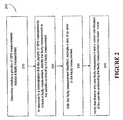
- FIG. 2 illustrates a method 200 for detecting and identifying a faulty GPS measurement among a plurality of GPS measurements obtained by the GPS receiver 122 with respect to the plurality of satellites 110.
- method 200 includes step 210 for determining whether the plurality of GPS measurements include a faulty measurement.
- method 200 further includes step 220 in which the faulty measurement is isolated or identified among the plurality of GPS measurements, or the satellite contributing to the faulty measurement is isolated or identified among the plurality of satellites.
- method 200 may include an optional step 230 in which a size of an error in the faulty measurement is determined, and an optional step 240 for verifying that the correct identification has been made.
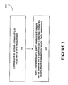
- FIG. 3 illustrates an embodiment of a method 300 for determining whether the GPS measurements include a faulty measurement in step 210.
- method 300 includes step 310 in which post-fix residuals corresponding to the plurality of GPS measurements are computed and step 320 in which a test statistics is formed using the post-fix residuals and is compared with a threshold to determine whether the plurality of GPS measurements include a faulty measurement.
- a residual of a GPS measurement represents a disagreement between the GPS measurement and a prediction or expected value of the GPS measurement. Before the position and clock bias of the GPS receiver are adjusted, the residuals are often referred to as pre-fix residuals or measurement innovations.
- a measurement innovation can be computed based on the difference between a GPS measurement and a theoretical prediction of the GPS measurement.
- a measurement innovation corresponding to a GPS measurement can be computed as the difference between the GPS measurement and an expected value of the GPS measurement computed from an initial estimated state of the GPS receiver, as discussed in the following.
- x is a state vector of the discrete-time controlled process and, in the case of GPS, it includes corrections to the position and clock bias of the GPS receiver
- H is a measurement sensitivity matrix including direction cosines of the state vector or unit vectors from the GPS receiver to each of the n satellites
- z is a measurement innovation vector including measurement innovations corresponding to the plurality of GPS measurements
- n is a measurement noise vector.
- the state vector may include an unknown ambiguity factor.
- the post-fix residuals are usually obtained in a two-step process.
- ⁇ is a residual vector including as its elements post-fix residuals corresponding to the plurality of GPS measurements
- each column (or row) of the S matrix includes residuals corresponding to a unit change in the measurement innovation of one of the plurality of satellites while the measurement innovations of the other ones of the plurality of satellites are kept unchanged.
- the post-fix residuals in the residual vector ⁇ can be computed according to Equation (5) in step 310.
- method 300 further includes step 320 in which the post-fix residuals or the root mean square residual are used to form a test statistic, which is then compared with a fault threshold to determine whether the plurality of GPS measurements include a faulty measurement.
- the fault threshold value is selected to correspond to the navigation mode used by the GPS receiver 122.
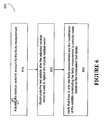
- FIG. 4 illustrates an embodiment of a method 400 for identifying the faulty measurement or a satellite contributing the faulty measurement in step 220 of method 200.
- method 400 includes step 410 in which a correlation value associated with each of the plurality of measurements or with each of the plurality of satellites is computed, and step 420 in which a satellite associated with a highest correlation value among the plurality of satellites 110 is identified as the satellite contributing the faulty measurement, or the GPS measurement with respect to the satellite associated with the highest correlation value is identified as the faulty measurement.
- the correlation value associated with each one of the plurality of satellites is computed based on a correlation coefficient associated with the satellite or with the one of the plurality of GPS measurements with respect to the satellite.
- s j the correlation coefficient associated with the j th satellite
- ⁇ i the i th element of the residual vector ⁇
- s i j the element in the i th row and j th column of the S matrix
- is the norm value of the residual vector ⁇
- s j represents the j th column of the S matrix
- the summation is over all elements of ⁇ or of the j th column of the S matrix.
- is equal to the square root of the diagonal element, s j j .
- the correlation value associated with a satellite is equal to the absolute value of the correlation coefficient associated with the satellite.
- the correlation coefficient associated with every satellite should be about one (or minus one). This is because the degree of freedom is only one (one more satellite than the number of unknowns in the state vector). With only five measurements corresponding to the five satellites, each column in the S matrix is perfectly correlated with the residual vector, except that the length of the columns are different. In other words, the large root mean square residual, which indicated a fault in step 210 of method 200, could be caused by a faulty measurement from any one of the satellites. Moreover, even when the number of satellites is greater than 5, a similar phenomenon can occur with a degenerate geometry. Such a degenerate geometry is indicated if more than one satellite are associated with correlation coefficients close to one or minus one.
- Method 500A or 500B can be used in step 420.
- Method 500A includes step 510A in which the highest correlation value is identified among the correlation values associated with the plurality of satellites.
- Method 500A further includes step 520A for determining that the highest correlation value exceed a predetermined threshold value and step 530A for determining that the predetermined threshold value is sufficiently larger than a second highest correlation value among the correlation values associated with the plurality of satellites.
- method 500B is used, which includes step 510B in which the highest and the second highest correlation values are identified, step 520B in which the difference between the highest and second highest correlation values are computed, and step 530B for determining that the difference exceeds a predetermined minimum difference value.
- method 200 may further include step 230 in which the size of any error in the faulty measurement (or the size of the fault) is estimated.
- Estimating the size of the fault is sometimes useful, especially when method 200 is used to identify a faulty measurement in a Real-Time Kinematic (RTK) navigation mode. Since RTK navigations usually involve carrier phase measurements and thus resolutions of whole-cycle ambiguities, a measurement fault can be the result of a cycle slip in a tracking loop or an improper determination of the whole-cycle ambiguity. When this is the case, the size of the fault will be a multiple of the carrier wavelength.
- method 200 may further include step 240 for verifying that there is only one faulty measurement among the plurality of GPS measurements and that the identification of the satellite contributing the faulty measurement is correctly made.
- FIG. 6 illustrates a method 600 for performing the verification in step 240.
- Method 600 further includes step 620 in which the test statistic is recalculated according to Equation (11), (12), or (12a) after the adjusted residual vector ⁇ ' is used to replace the residual vector ⁇ in the equation. If the fault identification has been made correctly, the recalculated test statistic should now pass the threshold test for the test statistic, indicating that the fault has been removed. Thus, method 600 further includes step 630 in which the recalculated test statistic is compared with the fault threshold to verify that there is only one faulty measurement among the plurality of GPS measurements and the identification of the satellite contributing the faulty measurement is correctly made.
- the above described method for identifying a faulty GPS measurement is computationally efficient because it works entirely in the measurement domain. When there are more than five satellites being tracked, the method can be used to dramatically improve the reliability of positioning and navigation using GPS, with only a small cost in additional computational complexity.
Abstract
Description
- The present invention relates generally to Fault Detection and Elimination (FDE) in a discrete-time controlled process, and particularly to methods for Receiver Autonomous Integrity Monitoring (RAIM) in global positioning systems (GPS).
- GPS uses satellites in space to locate objects on earth. With GPS, signals from the satellites arrive at a GPS receiver and are used to determine the position of the GPS receiver. Currently, two types of GPS measurements corresponding to each correlator channel with a locked GPS satellite signal are available for civilian GPS receivers. The two types of GPS measurements are pseudorange, and integrated carrier phase for two carrier signals, L1 and L2, with frequencies of 1.5754 GHz and 1.2276 GHz, or wavelengths of 0.1903 m and 0.2442 m, respectively. The pseudorange measurement (or code measurement) is a basic GPS observable that all types of GPS receivers can make. It utilizes the C/A or P codes modulated onto the carrier signals. The measurement records the apparent time taken for the relevant code to travel from the satellite to the receiver, i.e., the time the signal arrives at the receiver according to the receiver clock minus the time the signal left the satellite according to the satellite clock. The carrier phase measurement is obtained by integrating a reconstructed carrier of the signal as it arrives at the receiver. Thus, the carrier phase measurement is also a measure of a transit time difference as determined by the time the signal left the satellite according to the satellite clock and the time it arrives at the receiver according to the receiver clock. However, because an initial number of whole cycles in transit between the satellite and the receiver when the receiver starts tracking the carrier phase of the signal is usually not known, the transit time difference may be in error by multiple carrier cycles, i.e., there is a whole-cycle ambiguity in the carrier phase measurement.
- With the GPS measurements available, the range or distance between a GPS receiver and each of a multitude of satellites is calculated by multiplying a signal's travel time by the speed of light. These ranges are usually referred to as pseudoranges (false ranges) because the receiver clock generally has a significant time error which causes a common bias in the measured range. This common bias from receiver clock error is solved for along with the position coordinates of the receiver as part of the normal navigation computation. Various other factors can also lead to errors or noise in the calculated range, including ephemeris error, satellite clock timing error, atmospheric effects, receiver noise and multipath error. With standalone GPS navigation, where a user with a GPS receiver obtains code and/or carrier-phase ranges with respect to a plurality of satellites in view, without consulting with any reference station, the user is very limited in ways to reduce the errors or noises in the ranges.
- To eliminate or reduce these errors, differential operations are typically used in GPS applications. Differential GPS (DGPS) operations typically involve a base reference GPS receiver, a user GPS receiver, and a communication mechanism between the user and reference receivers. The reference receiver is placed at a known location and the known position is used to generate corrections associated with some or all of the above error factors. The corrections are supplied to the user receiver and the user receiver then uses the corrections to appropriately correct its computed position. The corrections can be in the form of corrections to the reference receiver position determined at the reference site or in the form of corrections to the specific GPS satellite clock and/or orbit. Corrections to the reference receiver position are not as flexible as GPS satellite clock or orbit corrections because, for optimum accuracy, they require that the same satellites be observed by the user receiver and the reference receiver.
- The fundamental concept of Differential GPS (DGPS) is to take advantage of the spatial and temporal correlations of the errors inherent in the GPS measurements to cancel the noise factors in the pseudorange and/or carrier phase measurements resulting from these error factors. However, while the GPS satellite clock timing error, which appears as a bias on the pseudorange or carrier phase measurement, is perfectly correlated between the reference receiver and the user receiver, most of the other error factors are either not correlated or the correlation diminishes in wide-area applications, i.e., when the distance between the reference and user receivers becomes large.
- To overcome the inaccuracy of the DGPS system in wide-area applications, various wide area DGPS (WADGPS) techniques have been developed. The WADGPS includes a network of multiple reference stations in communication with a computational center or hub. Error corrections are computed at the hub based upon the known locations of the reference stations and the measurements taken by them. The computed error corrections are then transmitted to users via a communication link such as satellite, phone, or radio. By using multiple reference stations, WADGPS provides more accurate estimates of the error corrections.
- Thus, a user with a GPS receiver may use different modes of navigation, i.e., standalone GPS, DGPS, WADGPS, carrier-phase DGPS, etc. Whichever of the navigation modes is used, there is always the possibility that the range with respect to a satellite are computed based on a faulty measurement, such as a measurement with respect to a failed satellite. When this range is used in determining the position of the user, an erroneous or wrong position would result. Thus, a faulty measurement can cause serious degradation to the reliability and integrity of the GPS system. Therefore, various integrity monitoring techniques have been developed for fault detection and elimination (FDE) in GPS systems. Receiver autonomous integrity monitoring (RAIM) is the name coined by the FAA for methods of integrity monitoring in GPS using redundant GPS satellite measurements.
- The literature on RAIM and FDE procedures is extensive. Most of the procedures in the literature, however, are related to aviation use and attempt to bound the probable error in a position domain. As a result, they generally involve very extensive computations. One of the earliest papers describing a RAIM procedure is a paper by Brown and McBurney, "Self-Contained GPS Integrity Check Using Maximum Solution Separation," Navigation, Vol. 35, No. 1, pp 41-53. In this paper, the authors suggest: (1) obtaining GPS measurements with respect to n satellites in view; (2) for each of the n satellites, solving for the user position based on measurements with respect to the other (n-1) satellites; (3) computing all possible distances between the solutions in the horizontal plane and determining a maximum distance among the possible distances; and (4) using the maximum distance as a test statistic and declaring a failure when the maximum distance exceeds a threshold. Clearly, this technique is very computationally intensive and does not isolate a particular measurement or satellite as being faulty.
- Another early paper is by Parkinson and Axelrad, "Autonomous GPS Integrity Monitoring Using the Pseudorange Residual," Navigation, Vol 35, No. 2, pp 255-271. In this paper, the authors suggest an excellent test statistic based upon pseudorange measurement residuals, but when it comes to using the test statistic to isolate a failed satellite, they use a scheme similar to that used by Brown and McBurney, i.e., for each of a plurality of satellites; they compute a test statistic while leaving out the measurement with respect to the satellite. Again, this procedure presents an excessive computational burden.
US 5931 889 describes a clock aided satellite navigation receiver system for monitoring the integrity of satellite signals in which a correlation is made between position error and clock bias error in the presence of faulty signals from a satellite in a satellite navigation system. - In accordance with an aspect of the present invention there is provided a method and system according to the accompanying claims.
A method for detecting and identifying a faulty measurement among a plurality of GPS measurements, obtained by a GPS receiver with respect to a plurality of satellites in view of the GPS receiver, determines whether the plurality of GPS measurements include a faulty measurement. In response to a determination that the plurality of GPS measurements include a fautly measurement, the method identifies a satellite contributing the faulty measurement by computing a correlation value associated with each of the plurality of satellites, and selecting a satellite associated with a highest correlation value as the satellite contributing the faulty measurement. In one embodiment, to insure that the correct satellite is identified, the satellite associated with the highest correlation value is selected when the highest correlation value exceeds a predetermined threshold value and the predetermined threshold value is sufficiently larger than a second highest correlation value. In an alternative embodiment the satellite associated with the highest correlation value is selected when the difference between the highest correlation value and a second highest correlation value exceeds a predetermined threshold. - In some embodiments, whether the GPS measurements include a faulty measurement is determined by computing test statistic using post-fix residuals corresponding to the plurality of GPS measurements, and comparing test statistic with a threshold residual value, which is chosen based on a navigation mode used by the GPS receiver. If the test statistic exceeds the threshold residual value, a faulty measurement is detected.
- In some embodiments, the correlation value associated with a satellite is the absolute value of a correlation coefficient associated with the satellite. The correlation coefficient is computed based on a residual sensitivity matrix corresponding to the plurality of satellites and a residual vector including the post-fix residuals corresponding to the plurality of GPS measurements.
- In some embodiments, the size of the error in the faulty GPS measurement is determined based on a residual sensitivity matrix corresponding to the plurality of satellites and the root mean square residual.
- Figure 1 is a block diagram of a computer system that can be used to carry out a method for detecting and identifying a faulty GPS measurement or a satellite contributing to the faulty GPS measurement.
- Figure 2 is a flowchart illustrating the method for detecting and identifying a faulty GPS measurement or a satellite contributing to the faulty GPS measurement.
- Figure 3 is a flowchart illustrating a method for determining whether a plurality of GPS measurements include a faulty GPS measurement.
- Figure 4 is a flowchart illustrating a method for identifying a faulty GPS measurement among a plurality of GPS measurements.
- Figure 5A is a flowchart illustrating a method for identifying a satellite with a highest correlation value as the satellite contributing to the faulty GPS measurement.
- Figure 5B is a flowchart illustrating another method for identifying a satellite with a highest correlation value as the satellite contributing to the faulty GPS measurement.
- Figure 6 is a flowchart illustrating a method for verifying that the satellite contributing to the faulty measurement has been identified correctly.
- FIG. 1 illustrates a
computer system 100 that can be used to carry out the method for detecting and identifying a faulty GPS measurement among a plurality of GPS measurements. Each of the plurality of GPS measurements is taken by aGPS receiver 122 based on signals from one of a plurality of satellites 110-1, 110-2, ..., 110-n, where n is the number of satellites in view of theGPS receiver 122. The plurality of satellites, or any one or more of them, are sometimes referred to hereafter in this document as satellite(s) 110. In some embodiments, theGPS receiver 122 and thecomputer system 100 are integrated into a single device, within a single housing, such as a portable, handheld or even wearable position tracking device, or a vehicle-mounted or otherwise mobile positioning and/or navigation system. In other embodiments, theGPS receiver 122 and thecomputer system 100 are not integrated into a single device. - As shown in FIG. 1, the
computer system 100 includes a central processing unit (CPU) 126,memory 128, aninput port 134 and anoutput port 136, and (optionally) auser interface 138, coupled to each other by one ormore communication buses 129. Thememory 128 may include high-speed random access memory and may include nonvolatile mass storage, such as one or more magnetic disk storage devices. Thememory 128 preferably stores anoperating system 131, adatabase 133, andGPS application procedures 135. The GPS application procedures may includeprocedures 137 for implementing the method for detecting and identifying the faulty GPS measurement, as described in more detail below. Theoperating system 131 and application programs andprocedures memory 128 are for execution by theCPU 126 of the computer system 124. Thememory 128 preferably also stores data structures used during execution of theGPS application procedures phase measurements 139, as well as other data structures discussed in this document. - The
input port 134 is for receiving data from theGPS receiver 122, andoutput port 136 is used for outputting data and/or calculation results. Data and calculation results may also be shown on a display device of theuser interface 138. - FIG. 2 illustrates a
method 200 for detecting and identifying a faulty GPS measurement among a plurality of GPS measurements obtained by theGPS receiver 122 with respect to the plurality ofsatellites 110. As shown in FIG. 2,method 200 includesstep 210 for determining whether the plurality of GPS measurements include a faulty measurement. In response to a determination instep 210 that the plurality of GPS measurements include a faulty measurement,method 200 further includesstep 220 in which the faulty measurement is isolated or identified among the plurality of GPS measurements, or the satellite contributing to the faulty measurement is isolated or identified among the plurality of satellites. With the satellite contributing the fault measurement identified,method 200 may include anoptional step 230 in which a size of an error in the faulty measurement is determined, and anoptional step 240 for verifying that the correct identification has been made. - FIG. 3 illustrates an embodiment of a
method 300 for determining whether the GPS measurements include a faulty measurement instep 210. As shown in FIG. 3,method 300 includesstep 310 in which post-fix residuals corresponding to the plurality of GPS measurements are computed and step 320 in which a test statistics is formed using the post-fix residuals and is compared with a threshold to determine whether the plurality of GPS measurements include a faulty measurement. A residual of a GPS measurement represents a disagreement between the GPS measurement and a prediction or expected value of the GPS measurement. Before the position and clock bias of the GPS receiver are adjusted, the residuals are often referred to as pre-fix residuals or measurement innovations. A measurement innovation can be computed based on the difference between a GPS measurement and a theoretical prediction of the GPS measurement. Alternatively, a measurement innovation corresponding to a GPS measurement can be computed as the difference between the GPS measurement and an expected value of the GPS measurement computed from an initial estimated state of the GPS receiver, as discussed in the following. - Whatever the navigation mode, navigating with GPS involves a discrete-time controlled process that is governed by a linear stochastic difference equation:

where x is a state vector of the discrete-time controlled process and, in the case of GPS, it includes corrections to the position and clock bias of the GPS receiver, H is a measurement sensitivity matrix including direction cosines of the state vector or unit vectors from the GPS receiver to each of the n satellites, z is a measurement innovation vector including measurement innovations corresponding to the plurality of GPS measurements, and n is a measurement noise vector. In the case of carrier-phase measurements, the state vector may include an unknown ambiguity factor.
The post-fix residuals are usually obtained in a two-step process. First, a least-squares solution for x is made, i.e.

for a weighted least squares solution. R in Equation (4) is a measurement covariance matrix and
where σ i , i=1,2, ..., n, represents a standard deviation of GPS measurement noises with respect to the ith satellite. An example of the methods for calculating σ i can be found in "Precision, Cross Correlation, and Time Correlation of GPS Phase and Code Observations," by Peter Bona, GPS Solutions, VoL 4, No. 2, Fall 2000, p. 3-13, or in " Tightly Integrated Attitude Determination Methods for Low-Cost Inertial Navigation : Two-Antenna GPS and GPS/Magnetometer," by Yang, Y., Ph.D. Dissertation, Dept. of Electrical Engineering, University of California, Riverside, CA June 2001. - The correction to the state as calculated in Equation (3) or (4) is used to transform the measurement innovations (pre-fix residuals) into a set of post fix residuals in
step 310 ofmethod 300, according to the following equations
where Δ is a residual vector including as its elements post-fix residuals corresponding to the plurality of GPS measurements, and S is a residual sensitivity matrix:
or,
- S is called the residual sensitivity matrix because it is a matrix whose elements are the residuals corresponding to unit changes in the measurement innovations. This can be explained through the following discussions. Equation (1) can be expanded to include a set of state vectors corresponding to a set of arbitrary measurement innovation vectors:

where X includes a set of state vectors x1, x2, ..., xn corresponding to a set of arbitrary measurement innovation vectors z 1, z 2,..., z n.. Now, if we let Z be an identity matrix, we get the state vectors corresponding to a set of measurement innovation vectors each representing a single unit change (e.g., one meter or any arbitrary unit) in the measurement innovation of a different respective one of the plurality of satellites while the measurement innovations of the other satellites are kept unchanged, as shown in the following equation:
The least-squares solution for X is then:
For a weighted least-squares solution this becomes:
- Multiplying equation (8) by H gives a prediction about the measurement innovations of each satellite based on the least-squares solution:

Subtracting this prediction from the input value of the innovations, i.e., the identity matrix, we obtain a matrix including the residuals of unit changes in the measurement innovations, which is the residual sensitivity matrix S in Equation (5a) or (5b). As shown in Equation (5), the S matrix can be used to directly map the pre-fix residuals (measurement innovations) into the post-fix residuals. - Thus, each column (or row) of the S matrix includes residuals corresponding to a unit change in the measurement innovation of one of the plurality of satellites while the measurement innovations of the other ones of the plurality of satellites are kept unchanged. The S matrix has a number of interesting properties: it is symmetric; it is idempotent, i.e., S=S2=S3= ... ; the sum of the elements in any row or column equals zero; and the length of any row or column is equal to the square root of an associated diagonal element. Since the state vector, x, has four elements for most navigation modes, the rank of S is n-4, where n is the number of satellites.
- With the S matrix, the post-fix residuals in the residual vector Δ can be computed according to Equation (5) in
step 310. The post-fix residuals can be used to compute a root mean square residual δ, which is the norm value (or length) of a residual vector Δ divided by the number of measurements, n, i.e.,
- After computing the post-fix residuals in
step 310,method 300 further includesstep 320 in which the post-fix residuals or the root mean square residual are used to form a test statistic, which is then compared with a fault threshold to determine whether the plurality of GPS measurements include a faulty measurement. The test statistic can be the root mean square residual. Or, it can be the length of the post-fix residual vector scaled by appropriate normalization for the number of satellites, such as the square root of (n-4), as in the following equation
Alternatively, when one is not concerned with very small errors, the fault threshold can be set large enough so that the scaling is relatively insignificant. Thus, the test statistic σ can simply be the length of the post-fix residual vector, i.e.,
- When the test statistic is larger than the fault threshold, it is determined that the plurality of GPS measurements include a faulty measurement. Since the level of measurement noise (or the position accuracy) of the
GPS receiver 122 often depends on the navigation mode in which the GPS receiver is operating, in some embodiments the fault threshold value is selected to correspond to the navigation mode used by theGPS receiver 122. - FIG. 4 illustrates an embodiment of a
method 400 for identifying the faulty measurement or a satellite contributing the faulty measurement instep 220 ofmethod 200. As shown in FIG. 4,method 400 includesstep 410 in which a correlation value associated with each of the plurality of measurements or with each of the plurality of satellites is computed, and step 420 in which a satellite associated with a highest correlation value among the plurality ofsatellites 110 is identified as the satellite contributing the faulty measurement, or the GPS measurement with respect to the satellite associated with the highest correlation value is identified as the faulty measurement. - In some embodiments, the correlation value associated with each one of the plurality of satellites is computed based on a correlation coefficient associated with the satellite or with the one of the plurality of GPS measurements with respect to the satellite. The correlation coefficient associated with a satellite, e.g., the jth satellite, where j = 1, 2, ... , n, represents a correlation between the residuals of the plurality of GPS measurements and the residuals corresponding to a unit change in the measurement innovations with respect to the jth satellite, while the measurement innovations of the other satellites are kept unchanged. Thus, the correlation coefficient associated with the jth satellite can be computed using the S matrix and the residual vector Δ according to the following equation:

where ρj is the correlation coefficient associated with the jth satellite, Δ i is the ith element of the residual vector Δ,

- In one embodiment, the correlation value associated with a satellite is equal to the absolute value of the correlation coefficient associated with the satellite. With the correlation values thus computed, the satellite associated with a highest correlation value among the correlation values associated with the plurality of satellites can generally be identified in
step 420 as the satellite contributing to the faulty measurement. However, an additional check may be required to ensure that the correct satellite is identified. - When only five satellites are available, the correlation coefficient associated with every satellite should be about one (or minus one). This is because the degree of freedom is only one (one more satellite than the number of unknowns in the state vector). With only five measurements corresponding to the five satellites, each column in the S matrix is perfectly correlated with the residual vector, except that the length of the columns are different. In other words, the large root mean square residual, which indicated a fault in
step 210 ofmethod 200, could be caused by a faulty measurement from any one of the satellites. Moreover, even when the number of satellites is greater than 5, a similar phenomenon can occur with a degenerate geometry. Such a degenerate geometry is indicated if more than one satellite are associated with correlation coefficients close to one or minus one. - Thus, to insure that the satellite contributing to the faulty measurement be identified correctly,
method step 420.Method 500A includesstep 510A in which the highest correlation value is identified among the correlation values associated with the plurality of satellites.Method 500A further includesstep 520A for determining that the highest correlation value exceed a predetermined threshold value and step 530A for determining that the predetermined threshold value is sufficiently larger than a second highest correlation value among the correlation values associated with the plurality of satellites. Alternatively,method 500B is used, which includesstep 510B in which the highest and the second highest correlation values are identified,step 520B in which the difference between the highest and second highest correlation values are computed, and step 530B for determining that the difference exceeds a predetermined minimum difference value. - With the satellite contributing the faulty measurement identified,
method 200 may further includestep 230 in which the size of any error in the faulty measurement (or the size of the fault) is estimated. Estimating the size of the fault is sometimes useful, especially whenmethod 200 is used to identify a faulty measurement in a Real-Time Kinematic (RTK) navigation mode. Since RTK navigations usually involve carrier phase measurements and thus resolutions of whole-cycle ambiguities, a measurement fault can be the result of a cycle slip in a tracking loop or an improper determination of the whole-cycle ambiguity. When this is the case, the size of the fault will be a multiple of the carrier wavelength. Given that the satellite, such as satellite 110-k, where k is 1, 2, ..., or n, with the highest correlation value is identified, a best estimate of the size of the error, ek, is given by the root mean square residual divided by the length of the column of the S matrix associated with the satellite 100-j. So, e k is the root mean square residual corresponding to a unit change in the measurement innovation of satellite-k while the measurement innovations for the rest of the plurality of satellites are kept unchanged. Since the length of the column of the S matrix is equal to the square root of the corresponding diagonal element of the S matrix, we have:
Note that with poor geometry the diagonal element can be small. However, the smaller the diagonal element, the larger the measurement error from the corresponding satellite must be before it can cause the root mean square residual to exceed the detection threshold. - With the size of the error in the faulty measurement estimated,
method 200 may further includestep 240 for verifying that there is only one faulty measurement among the plurality of GPS measurements and that the identification of the satellite contributing the faulty measurement is correctly made. FIG. 6 illustrates amethod 600 for performing the verification instep 240. As shown in FIG. 6,method 600 includesstep 610 in which the residual vector Δ is adjusted to account for the error according to the following equation:
where E is a vector with zero elements corresponding to satellites whose measurements are without error and an element having the value of ek for the satellite 100-k that contributed the faulty measurement.Method 600 further includesstep 620 in which the test statistic is recalculated according to Equation (11), (12), or (12a) after the adjusted residual vector Δ' is used to replace the residual vector Δ in the equation. If the fault identification has been made correctly, the recalculated test statistic should now pass the threshold test for the test statistic, indicating that the fault has been removed. Thus,method 600 further includesstep 630 in which the recalculated test statistic is compared with the fault threshold to verify that there is only one faulty measurement among the plurality of GPS measurements and the identification of the satellite contributing the faulty measurement is correctly made. - The above described method for identifying a faulty GPS measurement is computationally efficient because it works entirely in the measurement domain. When there are more than five satellites being tracked, the method can be used to dramatically improve the reliability of positioning and navigation using GPS, with only a small cost in additional computational complexity.
Claims (20)
- A method for identifying a faulty measurement among a plurality of GPS measurements comprising:computing a plurality of correlation values (410), each correlation value associated with one of the plurality of GPS measurements obtained by a GPS receiver with respect to a plurality of satellites, each of the plurality of GPS measurements corresponding to one of the plurality of satellites; andselecting a GPS measurement among the plurality of GPS measurements as the faulty measurement based on the correlation values (420);wherein:the correlation value associated with each one of the plurality of GPS measurements representing a correlation between residuals of the plurality of measurements and residuals corresponding to a change in the one of the plurality of GPS measurements while the rest of the plurality of GPS measurements are unchanged (310).
- The method of claim 1 wherein computing the correlation value associated with each one of the plurality of measurements comprises:computing a residual sensitivity matrix;computing residuals corresponding to the plurality of measurements; andcomputing a correlation coefficient associated with the one of the plurality of measurements based on the residuals of the plurality of measurements and the residual sensitivity matrix.
- The method of claim 2 wherein computing the residuals corresponding to the plurality of measurements comprises:obtaining a least-squares solution of the state of the discrete-time controlled process;computing expected values of the plurality of measurements based on the least-square solution; andcomputing differences between the plurality of measurements and the expected values of the plurality of measurements.
- The method of claim 2 wherein the residuals corresponding to the plurality of measurements are computed using the residual sensitivity matrix.
- The method of claim 1 wherein selecting a measurement among the plurality of measurements as the faulty measurement comprises:identifying a highest correlation value; andselecting the measurement associated with the highest correlation value as the faulty measurement.
- The method of claim 5, wherein selecting the measurement associated with the highest correlation value as the faulty measurement comprises:identifying a second highest correlation value; andselecting the measurement associated with the highest correlation value as the faulty measurement when the difference between the highest correlation value and the second highest correlation value exceeds a predetermined threshold value.
- The method of claim 5 wherein selecting the measurement associated with the highest correlation value as the faulty measurement comprises:determining that the highest correlation value exceeds a first predetermined threshold value;identifying a second highest correlation value; anddetermining that the second highest correlation value is smaller the first predetermined threshold value and the difference between the first predetermined threshold value and the second highest correlation value exceeds a second predetermined threshold value.
- The method of claim 1 wherein the state of the discrete-time controlled process includes corrections to a position and a clock bias of a GPS receiver and the plurality of measurements are GPS range measurements obtained by the GPS receiver with respect to a plurality of satellites, each of the plurality of measurements corresponding to one of the plurality of satellites.
- The method of claim 1 wherein the number of the plurality of satellites is greater than 5.
- The method of claim 1, further comprising:determining a size of an error in the faulty measurement, including dividing a root mean square residual of the plurality of GPS measurements by a root mean square residual corresponding to a unit change in the one of the plurality of GPS measurements while the rest of the plurality of GPS measurements are unchanged.
- The method of claim 1, further comprising:determining a size of an error in the faulty measurement, including dividing a root mean square residual of the plurality of measurements by the square root of a diagonal element corresponding to the faulty measurement in a residual sensitivity matrix.
- The method of claim 1, further comprising:verifying that the satellite contributing to the faulty measurement has been correctly identified.
- The method of claim 12 wherein verifying that the satellite contributing to the faulty measurement has been correctly identified comprises:adjusting the post-fix residuals based on the size of the error in the faulty GPS measurement;computing the test statistic using the adjusted post-fix residuals; andverifying that the test statistic does not exceed the fault threshold.
- A computer readable medium comprising computer executable program instructions that when executed cause a digital processing system to perform the method of any of claims 1 through 13.
- A system, comprising.
means (126, 137) for computing a plurality of correlation values, each correlation value associated with one of a plurality of GPS measurements obtained by a GPS receiver with respect to a plurality of satellites, each of the plurality of GPS measurements corresponding to one of the plurality of satellites; and
means (137) for selecting a GPS measurement among the plurality of GPS measurements as the faulty measurement based on the correlation values;
characterized by:the correlation value associated with each one of the plurality of GPS measurements representing a correlation between residuals of the plurality of measurements and residuals corresponding to a change in the one of the plurality of GPS measurements while the rest of the plurality of GPS measurements are unchanged. - The system of claim 15, wherein the means for computing the correlation value associated with each one of the plurality of measurements comprises means for computing a residual sensitivity matrix, for computing residuals corresponding to the plurality of measurements, and for computing a correlation coefficient associated with the one of the plurality of measurements based on the residuals of the plurality of measurements and the residual sensitivity matrix.
- The system of claim 16, wherein the means for computing the residuals corresponding to the plurality of measurements comprises means for obtaining a least-squares solution of the state of the discrete-time controlled process, for computing expected values of the plurality of measurements based on the least-square solution, and for computing differences between the plurality of measurements and the expected values of the plurality of measurements.
- The system of claim 16, wherein the residuals corresponding to the plurality of measurements are computed using the residual sensitivity matrix.
- The system of claim 15 wherein the means for selecting a measurement among the plurality of measurements as the faulty measurement comprises means for identifying a highest correlation value, and for selecting the measurement associated with the highest correlation value as the faulty measurement.
- The system of claim 19, wherein the means for selecting the measurement associated with the highest correlation value as the faulty measurement comprises means for identifying a second highest correlation value, and for selecting the measurement associated with the highest correlation value as the faulty measurement when the difference between the highest correlation value and the second highest correlation value exceeds a predetermined threshold value.
Applications Claiming Priority (2)
| Application Number | Priority Date | Filing Date | Title |
|---|---|---|---|
| US10/656,956 US6864836B1 (en) | 2003-09-05 | 2003-09-05 | Method for receiver autonomous integrity monitoring and fault detection and elimination |
| PCT/US2004/027344 WO2005027283A2 (en) | 2003-09-05 | 2004-08-19 | Method for receiver autonomous integrity monitoring and fault detection and elimination |
Publications (2)
| Publication Number | Publication Date |
|---|---|
| EP1660903A2 EP1660903A2 (en) | 2006-05-31 |
| EP1660903B1 true EP1660903B1 (en) | 2007-10-17 |
Family
ID=34218150
Family Applications (1)
| Application Number | Title | Priority Date | Filing Date |
|---|---|---|---|
| EP04786560A Not-in-force EP1660903B1 (en) | 2003-09-05 | 2004-08-19 | Method for receiver autonomous integrity monitoring and fault detection and elimination |
Country Status (11)
| Country | Link |
|---|---|
| US (1) | US6864836B1 (en) |
| EP (1) | EP1660903B1 (en) |
| JP (1) | JP2007504469A (en) |
| CN (1) | CN1846147A (en) |
| AT (1) | ATE376193T1 (en) |
| AU (1) | AU2004273434A1 (en) |
| BR (1) | BRPI0413975A (en) |
| CA (1) | CA2535713A1 (en) |
| DE (1) | DE602004009590T2 (en) |
| ES (1) | ES2294549T3 (en) |
| WO (1) | WO2005027283A2 (en) |
Families Citing this family (48)
| Publication number | Priority date | Publication date | Assignee | Title |
|---|---|---|---|---|
| US8131463B2 (en) * | 2003-12-02 | 2012-03-06 | Gmv Aerospace And Defence, S.A. | GNSS navigation solution integrity in non-controlled environments |
| US20060047413A1 (en) * | 2003-12-02 | 2006-03-02 | Lopez Nestor Z | GNSS navigation solution integrity in non-controlled environments |
| US7212155B2 (en) * | 2004-05-07 | 2007-05-01 | Navcom Technology, Inc. | GPS navigation using successive differences of carrier-phase measurements |
| JP4548604B2 (en) * | 2005-06-14 | 2010-09-22 | 三菱自動車工業株式会社 | Inter-vehicle communication system |
| US7501981B2 (en) * | 2005-11-18 | 2009-03-10 | Texas Instruments Incorporated | Methods and apparatus to detect and correct integrity failures in satellite positioning system receivers |
| US7286083B2 (en) * | 2005-12-15 | 2007-10-23 | Motorola, Inc. | Method and apparatus for improving fault detection and exclusion systems |
| US7733268B2 (en) * | 2006-05-16 | 2010-06-08 | Andrew Corporation | Method and apparatus for determining the geographic location of a device |
| FR2905006B1 (en) * | 2006-08-21 | 2008-10-17 | Airbus France Sas | METHOD OF MONITORING THE INTEGRITY OF A PLANE POSITION CALCULATED ON BOARD |
| US7436354B2 (en) * | 2006-09-07 | 2008-10-14 | The Mitre Corporation | Methods and systems for mobile navigational applications using global navigation satellite systems |
| JP2008281552A (en) * | 2007-04-09 | 2008-11-20 | Seiko Epson Corp | Method and program for calculating and determining first located output position, storage medium, positioning device, and electronic equipment |
| US7956802B1 (en) * | 2007-05-21 | 2011-06-07 | Rockwell Collins, Inc. | Integrity-optimized receiver autonomous integrity monitoring (RAIM) for vertical integrity monitoring |
| FR2918470B1 (en) * | 2007-07-06 | 2009-09-18 | Thales Sa | METHOD FOR IMPROVING THE INTEGRITY AND SAFETY OF AN AVIONIC SYSTEM |
| US7800533B2 (en) * | 2008-11-24 | 2010-09-21 | Andrew, Llc | System and method for determining falsified geographic location of a mobile device |
| US20130138338A1 (en) * | 2011-11-30 | 2013-05-30 | Honeywell International Inc. | Graphical presentation of receiver autonomous integrity monitoring outage regions on an aircraft display |
| US9547086B2 (en) | 2013-03-26 | 2017-01-17 | Honeywell International Inc. | Selected aspects of advanced receiver autonomous integrity monitoring application to kalman filter based navigation filter |
| CN103308928B (en) * | 2013-05-24 | 2015-05-20 | 北京东方计量测试研究所 | Pseudo-range precision measurement system of satellite navigation signal simulator |
| CN103308930B (en) * | 2013-05-24 | 2015-05-20 | 北京东方计量测试研究所 | Pseudo-range precision measurement method of satellite navigation signal simulator |
| CN103308929A (en) * | 2013-05-24 | 2013-09-18 | 北京东方计量测试研究所 | Satellite navigation signal simulator used for pseudorange precision index measurement |
| CN103592657B (en) * | 2013-09-30 | 2016-08-31 | 北京大学 | A kind of low visible star single-mode RAIM implementation method based on clock correction auxiliary |
| CN103592658A (en) * | 2013-09-30 | 2014-02-19 | 北京大学 | New method for RAIM (receiver autonomous integrity monitoring) based on satellite selecting algorithm in multimode satellite navigation system |
| US9784844B2 (en) | 2013-11-27 | 2017-10-10 | Honeywell International Inc. | Architectures for high integrity multi-constellation solution separation |
| CN104297557B (en) * | 2014-10-08 | 2017-04-26 | 北京航空航天大学 | United navigation autonomous integrity monitoring method applicable to free flight of plurality of aircraft |
| US9915734B2 (en) * | 2014-10-23 | 2018-03-13 | Honeywell International Inc. | Systems and methods for averaging satellite sigmas and readmitting excluded satellite measurements into differential corrections and integrity monitors |
| US10684375B2 (en) * | 2015-01-05 | 2020-06-16 | Samsung Electronics Co., Ltd | Method of multiple satellite measurement failure detection and isolation for GNSS |
| US10386491B2 (en) * | 2015-11-23 | 2019-08-20 | Honeywell International Inc. | Efficient covariance matrix update |
| US9854398B1 (en) * | 2016-08-03 | 2017-12-26 | International Business Machines Corporation | System, method and recording medium for location verification |
| DE102016224804A1 (en) * | 2016-12-13 | 2018-06-14 | Bayerische Motoren Werke Aktiengesellschaft | Method for determining the position of a charging station for the wireless transmission of electrical energy to a vehicle |
| US10670729B2 (en) | 2017-08-18 | 2020-06-02 | Novatel Inc. | System and method to provide an ASIL qualifier for GNSS position and related values |
| US10473790B2 (en) | 2017-11-17 | 2019-11-12 | Swift Navigation, Inc. | Systems and methods for distributed dense network processing of satellite positioning data |
| US10578747B2 (en) | 2017-12-14 | 2020-03-03 | Swift Navigation, Inc. | Systems and methods for reduced-outlier satellite positioning |
| US10754041B2 (en) | 2018-09-28 | 2020-08-25 | The Mitre Corporation | Identifying and partitioning legitimate GNSS satellite signals from illegitimate GNSS satellite signals using a contrario method |
| CN114174850A (en) | 2019-05-01 | 2022-03-11 | 斯威夫特导航股份有限公司 | System and method for high integrity satellite positioning |
| EP4007928A4 (en) | 2019-08-01 | 2023-12-20 | Swift Navigation, Inc. | System and method for gaussian process enhanced gnss corrections generation |
| US11493934B2 (en) * | 2019-08-07 | 2022-11-08 | GM Global Technology Operations LLC | GPS data integrity verification |
| WO2021202004A2 (en) | 2020-02-14 | 2021-10-07 | Swift Navigation, Inc. | System and method for reconverging gnss position estimates |
| CN111580136B (en) * | 2020-04-26 | 2022-11-01 | 北京时代民芯科技有限公司 | Receiver autonomous integrity fault detection method |
| US11480690B2 (en) | 2020-06-09 | 2022-10-25 | Swift Navigation, Inc. | System and method for satellite positioning |
| US11378699B2 (en) | 2020-07-13 | 2022-07-05 | Swift Navigation, Inc. | System and method for determining GNSS positioning corrections |
| CN116324511A (en) | 2020-07-17 | 2023-06-23 | 斯威夫特导航股份有限公司 | System and method for providing GNSS corrections |
| US11668839B2 (en) | 2020-11-30 | 2023-06-06 | Honeywell International Inc. | Terrain database assisted GNSS spoofing determination using radar observations |
| US11467290B2 (en) | 2020-11-30 | 2022-10-11 | Honeywell International Inc. | GNSS signal spoofing detection via bearing and/or range sensor observations |
| WO2022133294A1 (en) | 2020-12-17 | 2022-06-23 | Swift Navigation, Inc. | System and method for fusing dead reckoning and gnss data streams |
| US11733397B2 (en) | 2021-07-24 | 2023-08-22 | Swift Navigation, Inc. | System and method for computing positioning protection levels |
| US11693120B2 (en) | 2021-08-09 | 2023-07-04 | Swift Navigation, Inc. | System and method for providing GNSS corrections |
| CN114114351B (en) * | 2022-01-24 | 2022-07-12 | 浙江时空道宇科技有限公司 | Method, device and equipment for eliminating satellite navigation measurement fault and storage medium |
| US11906640B2 (en) | 2022-03-01 | 2024-02-20 | Swift Navigation, Inc. | System and method for fusing sensor and satellite measurements for positioning determination |
| US11860287B2 (en) | 2022-03-01 | 2024-01-02 | Swift Navigation, Inc. | System and method for detecting outliers in GNSS observations |
| CN115494527B (en) * | 2022-04-13 | 2023-10-31 | 无锡奇芯科技有限公司 | Satellite system fault removal method based on correlation coefficient |
Family Cites Families (12)
| Publication number | Priority date | Publication date | Assignee | Title |
|---|---|---|---|---|
| DE4340746C2 (en) * | 1992-11-30 | 2003-11-27 | Toyota Chuo Kenkyusho Aichi Kk | Diagnostic device for diagnosing a dynamic system |
| US5544308A (en) * | 1994-08-02 | 1996-08-06 | Giordano Automation Corp. | Method for automating the development and execution of diagnostic reasoning software in products and processes |
| US5931889A (en) * | 1995-01-24 | 1999-08-03 | Massachusetts Institute Of Technology | Clock-aided satellite navigation receiver system for monitoring the integrity of satellite signals |
| US5680409A (en) * | 1995-08-11 | 1997-10-21 | Fisher-Rosemount Systems, Inc. | Method and apparatus for detecting and identifying faulty sensors in a process |
| US5841399A (en) * | 1996-06-28 | 1998-11-24 | Alliedsignal Inc. | Fault detection and exclusion used in a global positioning system GPS receiver |
| US6114988A (en) * | 1996-12-31 | 2000-09-05 | Honeywell Inc. | GPS receiver fault detection method and system |
| US6204806B1 (en) * | 1999-02-26 | 2001-03-20 | Rockwell Collins, Inc. | Method of enhancing receiver autonomous GPS navigation integrity monitoring and GPS receiver implementing the same |
| US6691066B1 (en) * | 2000-08-28 | 2004-02-10 | Sirf Technology, Inc. | Measurement fault detection |
| US6502042B1 (en) * | 2000-10-26 | 2002-12-31 | Bfgoodrich Aerospace Fuel And Utility Systems | Fault tolerant liquid measurement system using multiple-model state estimators |
| US6515618B1 (en) * | 2000-11-29 | 2003-02-04 | Trimble Navigation Ltd. | Fault detection and exclusion in a positioning system receiver |
| JP4328531B2 (en) * | 2001-03-09 | 2009-09-09 | ハミルトン・ボナドゥーツ・アーゲー | Method and apparatus for evaluating process of dispensing predetermined amount of liquid |
| US6962043B2 (en) * | 2003-01-30 | 2005-11-08 | General Electric Company | Method and apparatus for monitoring the performance of a gas turbine system |
-
2003
- 2003-09-05 US US10/656,956 patent/US6864836B1/en not_active Expired - Lifetime
-
2004
- 2004-08-19 ES ES04786560T patent/ES2294549T3/en active Active
- 2004-08-19 DE DE602004009590T patent/DE602004009590T2/en not_active Expired - Fee Related
- 2004-08-19 AU AU2004273434A patent/AU2004273434A1/en not_active Abandoned
- 2004-08-19 BR BRPI0413975-5A patent/BRPI0413975A/en not_active IP Right Cessation
- 2004-08-19 AT AT04786560T patent/ATE376193T1/en not_active IP Right Cessation
- 2004-08-19 JP JP2006526112A patent/JP2007504469A/en not_active Withdrawn
- 2004-08-19 CN CNA2004800253902A patent/CN1846147A/en active Pending
- 2004-08-19 EP EP04786560A patent/EP1660903B1/en not_active Not-in-force
- 2004-08-19 CA CA002535713A patent/CA2535713A1/en not_active Abandoned
- 2004-08-19 WO PCT/US2004/027344 patent/WO2005027283A2/en active IP Right Grant
Non-Patent Citations (1)
| Title |
|---|
| None * |
Also Published As
| Publication number | Publication date |
|---|---|
| US20050052319A1 (en) | 2005-03-10 |
| JP2007504469A (en) | 2007-03-01 |
| ES2294549T3 (en) | 2008-04-01 |
| BRPI0413975A (en) | 2006-10-31 |
| WO2005027283A3 (en) | 2005-06-02 |
| AU2004273434A1 (en) | 2005-03-24 |
| DE602004009590D1 (en) | 2007-11-29 |
| CN1846147A (en) | 2006-10-11 |
| EP1660903A2 (en) | 2006-05-31 |
| CA2535713A1 (en) | 2005-03-24 |
| DE602004009590T2 (en) | 2008-07-24 |
| ATE376193T1 (en) | 2007-11-15 |
| US6864836B1 (en) | 2005-03-08 |
| WO2005027283A2 (en) | 2005-03-24 |
Similar Documents
| Publication | Publication Date | Title |
|---|---|---|
| EP1660903B1 (en) | Method for receiver autonomous integrity monitoring and fault detection and elimination | |
| US10018729B2 (en) | Selected aspects of advanced receiver autonomous integrity monitoring application to kalman filter based navigation filter | |
| EP2068165B1 (en) | Navigation system with apparatus for detecting accuracy failures | |
| EP1704421B1 (en) | A method for combined use of a local rtk system and a regional, wide-area, or global carrier-phase positioning system | |
| JP5421903B2 (en) | Partial search carrier phase integer ambiguity determination | |
| EP1678516B1 (en) | Method for using three gps frequencies to resolve carrier-phase integer ambiguities | |
| US5914685A (en) | Relative position measuring techniques using both GPS and GLONASS carrier phase measurements | |
| US9405012B2 (en) | Advanced global navigation satellite systems (GNSS) positioning using precise satellite information | |
| EP2336807B1 (en) | Method and software product for determining code and phase biases of satellite signals | |
| US6166683A (en) | System and method for high-integrity detection and correction of cycle slip in a carrier phase-related system | |
| US5917445A (en) | GPS multipath detection method and system | |
| EP0694791A1 (en) | Method and system for resolving double difference GPS carrier phase integer ambiguity utilizing decentralized kalman filters | |
| US20060229805A1 (en) | Method and apparatus for navigation using instantaneous doppler measurements from satellites | |
| US20050024263A1 (en) | Method for generating clock corrections for a wide-area or global differential GPS system | |
| Castaldo et al. | P-RANSAC: An Integrity Monitoring Approach for GNSS Signal Degraded Scenario. | |
| CN101395443A (en) | Hybrid positioning method and device | |
| US11320540B2 (en) | Integrity monitoring of primary and derived parameters | |
| JP5566598B2 (en) | Navigation system comprising a device for detecting inaccuracy | |
| Wolfe et al. | Hypothesis testing for resolving integer ambiguity in GPS | |
| JP5566599B2 (en) | Navigation system having a device for detecting inaccuracy | |
| Geier et al. | AD-A262 830 DREDGING RESEARCH PROGRAM | |
| RESOLUTION | Ionospheric Modeling |
Legal Events
| Date | Code | Title | Description |
|---|---|---|---|
| PUAI | Public reference made under article 153(3) epc to a published international application that has entered the european phase |
Free format text: ORIGINAL CODE: 0009012 |
|
| 17P | Request for examination filed |
Effective date: 20060310 |
|
| AK | Designated contracting states |
Kind code of ref document: A2 Designated state(s): AT BE BG CH CY CZ DE DK EE ES FI FR GB GR HU IE IT LI LU MC NL PL PT RO SE SI SK TR |
|
| 17Q | First examination report despatched |
Effective date: 20060630 |
|
| DAX | Request for extension of the european patent (deleted) | ||
| GRAP | Despatch of communication of intention to grant a patent |
Free format text: ORIGINAL CODE: EPIDOSNIGR1 |
|
| GRAS | Grant fee paid |
Free format text: ORIGINAL CODE: EPIDOSNIGR3 |
|
| GRAA | (expected) grant |
Free format text: ORIGINAL CODE: 0009210 |
|
| AK | Designated contracting states |
Kind code of ref document: B1 Designated state(s): AT BE BG CH CY CZ DE DK EE ES FI FR GB GR HU IE IT LI LU MC NL PL PT RO SE SI SK TR |
|
| REG | Reference to a national code |
Ref country code: GB Ref legal event code: FG4D |
|
| REG | Reference to a national code |
Ref country code: CH Ref legal event code: EP |
|
| REG | Reference to a national code |
Ref country code: IE Ref legal event code: FG4D |
|
| REF | Corresponds to: |
Ref document number: 602004009590 Country of ref document: DE Date of ref document: 20071129 Kind code of ref document: P |
|
| NLV1 | Nl: lapsed or annulled due to failure to fulfill the requirements of art. 29p and 29m of the patents act | ||
| REG | Reference to a national code |
Ref country code: ES Ref legal event code: FG2A Ref document number: 2294549 Country of ref document: ES Kind code of ref document: T3 |
|
| PG25 | Lapsed in a contracting state [announced via postgrant information from national office to epo] |
Ref country code: SE Free format text: LAPSE BECAUSE OF FAILURE TO SUBMIT A TRANSLATION OF THE DESCRIPTION OR TO PAY THE FEE WITHIN THE PRESCRIBED TIME-LIMIT Effective date: 20080117 Ref country code: LI Free format text: LAPSE BECAUSE OF FAILURE TO SUBMIT A TRANSLATION OF THE DESCRIPTION OR TO PAY THE FEE WITHIN THE PRESCRIBED TIME-LIMIT Effective date: 20071017 Ref country code: CH Free format text: LAPSE BECAUSE OF FAILURE TO SUBMIT A TRANSLATION OF THE DESCRIPTION OR TO PAY THE FEE WITHIN THE PRESCRIBED TIME-LIMIT Effective date: 20071017 Ref country code: NL Free format text: LAPSE BECAUSE OF FAILURE TO SUBMIT A TRANSLATION OF THE DESCRIPTION OR TO PAY THE FEE WITHIN THE PRESCRIBED TIME-LIMIT Effective date: 20071017 |
|
| REG | Reference to a national code |
Ref country code: CH Ref legal event code: PL |
|
| PG25 | Lapsed in a contracting state [announced via postgrant information from national office to epo] |
Ref country code: BG Free format text: LAPSE BECAUSE OF FAILURE TO SUBMIT A TRANSLATION OF THE DESCRIPTION OR TO PAY THE FEE WITHIN THE PRESCRIBED TIME-LIMIT Effective date: 20080117 Ref country code: PL Free format text: LAPSE BECAUSE OF FAILURE TO SUBMIT A TRANSLATION OF THE DESCRIPTION OR TO PAY THE FEE WITHIN THE PRESCRIBED TIME-LIMIT Effective date: 20071017 Ref country code: PT Free format text: LAPSE BECAUSE OF FAILURE TO SUBMIT A TRANSLATION OF THE DESCRIPTION OR TO PAY THE FEE WITHIN THE PRESCRIBED TIME-LIMIT Effective date: 20080317 Ref country code: SI Free format text: LAPSE BECAUSE OF FAILURE TO SUBMIT A TRANSLATION OF THE DESCRIPTION OR TO PAY THE FEE WITHIN THE PRESCRIBED TIME-LIMIT Effective date: 20071017 |
|
| ET | Fr: translation filed | ||
| PG25 | Lapsed in a contracting state [announced via postgrant information from national office to epo] |
Ref country code: AT Free format text: LAPSE BECAUSE OF FAILURE TO SUBMIT A TRANSLATION OF THE DESCRIPTION OR TO PAY THE FEE WITHIN THE PRESCRIBED TIME-LIMIT Effective date: 20071017 |
|
| PG25 | Lapsed in a contracting state [announced via postgrant information from national office to epo] |
Ref country code: CZ Free format text: LAPSE BECAUSE OF FAILURE TO SUBMIT A TRANSLATION OF THE DESCRIPTION OR TO PAY THE FEE WITHIN THE PRESCRIBED TIME-LIMIT Effective date: 20071017 Ref country code: DK Free format text: LAPSE BECAUSE OF FAILURE TO SUBMIT A TRANSLATION OF THE DESCRIPTION OR TO PAY THE FEE WITHIN THE PRESCRIBED TIME-LIMIT Effective date: 20071017 |
|
| PLBE | No opposition filed within time limit |
Free format text: ORIGINAL CODE: 0009261 |
|
| STAA | Information on the status of an ep patent application or granted ep patent |
Free format text: STATUS: NO OPPOSITION FILED WITHIN TIME LIMIT |
|
| PG25 | Lapsed in a contracting state [announced via postgrant information from national office to epo] |
Ref country code: RO Free format text: LAPSE BECAUSE OF FAILURE TO SUBMIT A TRANSLATION OF THE DESCRIPTION OR TO PAY THE FEE WITHIN THE PRESCRIBED TIME-LIMIT Effective date: 20071017 Ref country code: BE Free format text: LAPSE BECAUSE OF FAILURE TO SUBMIT A TRANSLATION OF THE DESCRIPTION OR TO PAY THE FEE WITHIN THE PRESCRIBED TIME-LIMIT Effective date: 20071017 Ref country code: SK Free format text: LAPSE BECAUSE OF FAILURE TO SUBMIT A TRANSLATION OF THE DESCRIPTION OR TO PAY THE FEE WITHIN THE PRESCRIBED TIME-LIMIT Effective date: 20071017 |
|
| 26N | No opposition filed |
Effective date: 20080718 |
|
| PGFP | Annual fee paid to national office [announced via postgrant information from national office to epo] |
Ref country code: ES Payment date: 20080826 Year of fee payment: 5 |
|
| PGFP | Annual fee paid to national office [announced via postgrant information from national office to epo] |
Ref country code: FR Payment date: 20080818 Year of fee payment: 5 Ref country code: IT Payment date: 20080825 Year of fee payment: 5 |
|
| PGFP | Annual fee paid to national office [announced via postgrant information from national office to epo] |
Ref country code: GB Payment date: 20080827 Year of fee payment: 5 |
|
| PG25 | Lapsed in a contracting state [announced via postgrant information from national office to epo] |
Ref country code: GR Free format text: LAPSE BECAUSE OF FAILURE TO SUBMIT A TRANSLATION OF THE DESCRIPTION OR TO PAY THE FEE WITHIN THE PRESCRIBED TIME-LIMIT Effective date: 20080118 |
|
| PGFP | Annual fee paid to national office [announced via postgrant information from national office to epo] |
Ref country code: DE Payment date: 20080930 Year of fee payment: 5 |
|
| PG25 | Lapsed in a contracting state [announced via postgrant information from national office to epo] |
Ref country code: FI Free format text: LAPSE BECAUSE OF FAILURE TO SUBMIT A TRANSLATION OF THE DESCRIPTION OR TO PAY THE FEE WITHIN THE PRESCRIBED TIME-LIMIT Effective date: 20071017 |
|
| PG25 | Lapsed in a contracting state [announced via postgrant information from national office to epo] |
Ref country code: MC Free format text: LAPSE BECAUSE OF NON-PAYMENT OF DUE FEES Effective date: 20080831 |
|
| PG25 | Lapsed in a contracting state [announced via postgrant information from national office to epo] |
Ref country code: EE Free format text: LAPSE BECAUSE OF FAILURE TO SUBMIT A TRANSLATION OF THE DESCRIPTION OR TO PAY THE FEE WITHIN THE PRESCRIBED TIME-LIMIT Effective date: 20071017 |
|
| PG25 | Lapsed in a contracting state [announced via postgrant information from national office to epo] |
Ref country code: CY Free format text: LAPSE BECAUSE OF FAILURE TO SUBMIT A TRANSLATION OF THE DESCRIPTION OR TO PAY THE FEE WITHIN THE PRESCRIBED TIME-LIMIT Effective date: 20071017 Ref country code: IE Free format text: LAPSE BECAUSE OF NON-PAYMENT OF DUE FEES Effective date: 20080819 |
|
| GBPC | Gb: european patent ceased through non-payment of renewal fee |
Effective date: 20090819 |
|
| REG | Reference to a national code |
Ref country code: FR Ref legal event code: ST Effective date: 20100430 |
|
| PG25 | Lapsed in a contracting state [announced via postgrant information from national office to epo] |
Ref country code: FR Free format text: LAPSE BECAUSE OF NON-PAYMENT OF DUE FEES Effective date: 20090831 Ref country code: DE Free format text: LAPSE BECAUSE OF NON-PAYMENT OF DUE FEES Effective date: 20100302 Ref country code: HU Free format text: LAPSE BECAUSE OF FAILURE TO SUBMIT A TRANSLATION OF THE DESCRIPTION OR TO PAY THE FEE WITHIN THE PRESCRIBED TIME-LIMIT Effective date: 20080418 Ref country code: LU Free format text: LAPSE BECAUSE OF NON-PAYMENT OF DUE FEES Effective date: 20080819 |
|
| PG25 | Lapsed in a contracting state [announced via postgrant information from national office to epo] |
Ref country code: TR Free format text: LAPSE BECAUSE OF FAILURE TO SUBMIT A TRANSLATION OF THE DESCRIPTION OR TO PAY THE FEE WITHIN THE PRESCRIBED TIME-LIMIT Effective date: 20071017 |
|
| REG | Reference to a national code |
Ref country code: ES Ref legal event code: FD2A Effective date: 20090820 |
|
| PG25 | Lapsed in a contracting state [announced via postgrant information from national office to epo] |
Ref country code: GB Free format text: LAPSE BECAUSE OF NON-PAYMENT OF DUE FEES Effective date: 20090819 |
|
| PG25 | Lapsed in a contracting state [announced via postgrant information from national office to epo] |
Ref country code: IT Free format text: LAPSE BECAUSE OF NON-PAYMENT OF DUE FEES Effective date: 20090819 |
|
| PG25 | Lapsed in a contracting state [announced via postgrant information from national office to epo] |
Ref country code: ES Free format text: LAPSE BECAUSE OF NON-PAYMENT OF DUE FEES Effective date: 20090820 |