EP1660844B1 - Flow meter filter system and method - Google Patents
Flow meter filter system and method Download PDFInfo
- Publication number
- EP1660844B1 EP1660844B1 EP03749480.4A EP03749480A EP1660844B1 EP 1660844 B1 EP1660844 B1 EP 1660844B1 EP 03749480 A EP03749480 A EP 03749480A EP 1660844 B1 EP1660844 B1 EP 1660844B1
- Authority
- EP
- European Patent Office
- Prior art keywords
- flow meter
- noise
- signal
- value
- damping
- Prior art date
- Legal status (The legal status is an assumption and is not a legal conclusion. Google has not performed a legal analysis and makes no representation as to the accuracy of the status listed.)
- Expired - Lifetime
Links
Images


Classifications
-
- G—PHYSICS
- G01—MEASURING; TESTING
- G01F—MEASURING VOLUME, VOLUME FLOW, MASS FLOW OR LIQUID LEVEL; METERING BY VOLUME
- G01F1/00—Measuring the volume flow or mass flow of fluid or fluent solid material wherein the fluid passes through a meter in a continuous flow
- G01F1/76—Devices for measuring mass flow of a fluid or a fluent solid material
- G01F1/78—Direct mass flowmeters
- G01F1/80—Direct mass flowmeters operating by measuring pressure, force, momentum, or frequency of a fluid flow to which a rotational movement has been imparted
- G01F1/84—Coriolis or gyroscopic mass flowmeters
- G01F1/8409—Coriolis or gyroscopic mass flowmeters constructional details
- G01F1/8436—Coriolis or gyroscopic mass flowmeters constructional details signal processing
-
- G—PHYSICS
- G01—MEASURING; TESTING
- G01F—MEASURING VOLUME, VOLUME FLOW, MASS FLOW OR LIQUID LEVEL; METERING BY VOLUME
- G01F1/00—Measuring the volume flow or mass flow of fluid or fluent solid material wherein the fluid passes through a meter in a continuous flow
-
- G—PHYSICS
- G01—MEASURING; TESTING
- G01F—MEASURING VOLUME, VOLUME FLOW, MASS FLOW OR LIQUID LEVEL; METERING BY VOLUME
- G01F15/00—Details of, or accessories for, apparatus of groups G01F1/00 - G01F13/00 insofar as such details or appliances are not adapted to particular types of such apparatus
-
- G—PHYSICS
- G01—MEASURING; TESTING
- G01F—MEASURING VOLUME, VOLUME FLOW, MASS FLOW OR LIQUID LEVEL; METERING BY VOLUME
- G01F15/00—Details of, or accessories for, apparatus of groups G01F1/00 - G01F13/00 insofar as such details or appliances are not adapted to particular types of such apparatus
- G01F15/06—Indicating or recording devices
-
- G—PHYSICS
- G01—MEASURING; TESTING
- G01F—MEASURING VOLUME, VOLUME FLOW, MASS FLOW OR LIQUID LEVEL; METERING BY VOLUME
- G01F25/00—Testing or calibration of apparatus for measuring volume, volume flow or liquid level or for metering by volume
Definitions
- the invention is related to the field of removing noise from a flow meter signal, and in particular, to removing cyclic noise, such as cross-talk noise, from the flow meter signal.
- Flow meters are used to measure the mass flow rate, density, and other information for flowing materials.
- the flowing materials can include liquids, gases, combined liquids and gases, solids suspended in liquids, and liquids including gases and suspended solids.
- flow meters are widely used in the well production and refining of petroleum and petroleum products.
- a flow meter can be used to determine well production by measuring a flow rate (i.e., by measuring a mass flow through the flow meter), and can even be used to determine the relative proportions of the gas and liquid components of a flow.
- Cross-talk is a phenomena when the flow meter signal from a first meter influences and corrupts a flow meter signal from a second flow meter (and vice versa).
- Cross-talk noise in a flow meter environment commonly is a relatively large, slow-moving signal typically no faster than 1 Hertz (Hz). The noise can degrade accuracy of the flowmeter signal and can lead to extremely large indicated flow errors. In addition, noise can occur due to other factors and other sources.
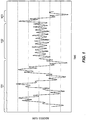
- FIG. 1 is a graph of a flow meter output signal taken over time. The figure shows how a flow meter signal is influenced by other flow meters.
- the time periods 101 and 103 in the figure show a flow meter signal when three flow meters are generating output, with two other flow meters therefore generating cross-talk noise in the current flow meter output.
- Time period 102 is a flow meter signal when only one other interfering flow meter is active. Note that the generated noise varies in both amplitude and frequency throughout the graph.
- US 6,594,613 discloses an adjustable bandwidth filter for process variable transmitter.
- the transmitter has a sensor with external sensors adapted to sense process variables.
- a filter coupled to the sensor has a bandwidth that decreases at higher sensor noise to damp noise and increases at lower sensor noise automatically.
- a communication circuit is coupled to the filter and provides a transmitter output of the process variables with adjusted damping in sensor noise.
- the invention helps solve the above problems with removing noise from a flow meter signal.
- a flow meter filter system (200) is provided according to an embodiment of the invention.
- the flow meter filter system (200) comprises a noise pass filter (203) configured to receive a first version of a flow meter signal and filter out the flow meter data from the flow meter signal to leave a noise signal.
- the flow meter filter system (200) further comprises a noise quantifier (204) configured to receive the noise signal from the noise pass filter (203) and measure noise characteristics of the noise signal.
- the flow meter filter system (200) further comprises a damping adjuster (205) configured to receive the noise characteristics from the noise quantifier (204) and generate a damping value based on the noise characteristics.
- the flow meter filter system (200) further comprises a filter element (206) configured to receive a second version of the flow meter signal and receive the damping value from the damping adjuster (205), with the filter element (206) being further configured to damp the second version of the flow meter signal based on the damping value in order to produce a filtered flow meter signal.
- a method of removing noise from a flow meter signal comprises the steps of receiving the flow meter signal, applying a large damping value to the flow meter signal in order to produce a filtered flow meter signal if the flow meter signal is substantially quiescent, and applying a small damping value to the flow meter signal in order to produce the filtered flow meter signal if the flow meter signal is experiencing a transition.
- a method of removing noise from a flow meter signal comprises the steps of receiving the flow meter signal, filtering a noise signal substantially out of a first version of the flow meter signal, measuring the noise signal to obtain noise characteristics, determining a damping value from the noise characteristics, with the damping value being selected to substantially remove the noise signal from the flow meter signal, and damping the noise substantially out of a second version of the flow meter signal using the damping value in order to produce a filtered flow meter signal.
- One aspect of the invention comprises normalizing the flow meter signal from an original value to a normalized value prior to the damping, and scaling the filtered flow meter signal of the damping step substantially back to the original flow meter signal magnitude.
- the method determines an error value between the second version of the flow meter signal and the filtered flow meter signal, and feeds the error value back into the determining of the damping value, wherein the error value is included in the damping value determination.
- the noise pass filter and the filter element comprise digital filters.
- the noise pass filter and the filter element comprise Infinite Impulse Response (IIR) digital filters.
- IIR Infinite Impulse Response
- the noise pass filter and the filter element comprise second-order IIR digital filters.
- the damping adjuster is further configured to generate the damping value based on the noise characteristics and on a damping delay coefficient.
- the flow meter signal comprises a Coriolis flow meter signal.
- FIGS. 2-9 and the following description depict specific examples of the invention to teach those skilled in the art how to make and use the best mode of the invention. For the purpose of teaching inventive principles, some conventional aspects of the invention have been simplified or omitted. Those skilled in the art will appreciate variations from these examples that fall within the scope of the invention as defined in the claims. Those skilled in the art will appreciate that the features described below can be combined in various ways to form multiple variations of the invention as defined in the claims. As a result, the invention is not limited to the specific examples described below, but only by the claims.
- FIG. 2 is a flow meter filter system 200 according to an embodiment of the invention.
- the flow meter filter system 200 receives a flow meter signal from one or more flow meters and substantially filters out noise in the flow meter signal.
- the flow meters can comprise any type of flow meter, including Coriolis flow meters, turbine flow meters, magnetic flow meters, etc.
- the flow meter filter system 200 in the embodiment shown includes a normalizer 201, a scaler 202, a noise pass filter 203, a noise quantifier 204, a damping adjuster 205, and a filter element 206. It should be understood that other flow meter filter configurations are contemplated within the scope of the claims, and that the embodiment shown is provided for illustration.
- the normalizer 201 receives the flow meter signal and a maximum flow value, and has an output that is connected to the filter element 206.
- the noise pass filter 203 also receives the flow meter signal (i.e., a first version of the flow meter signal), and has an output that is connected to the noise quantifier 204.
- the noise quantifier 204 receives the output of the noise pass filter 203, and has a maximum noise output and a zero offset output that are connected to the damping adjuster 205.
- the damping adjuster 205 also receives the maximum flow value, receives the maximum noise output and the zero offset outputted from the noise quantifier 204, and receives an error value outputted from the filter element 206.
- the damping adjuster 205 has a damping value output.
- the filter element 206 receives the normalized flow meter signal (i.e., a second version of the flow meter signal) outputted from the normalizer 201 and the damping value outputted from the damping adjuster 205, and has as outputs the error value and a filtered flow meter signal with the noise damped out.
- the scaler 202 receives the filtered flow meter signal that is outputted from the filter element 206 and also receives a version of the maximum flow value, and outputs a scaled, filtered version of the flow meter signal.
- a flow meter signal is input into the flow meter filter system 200.
- the flow meter filter system 200 measures noise characteristics of the noise, and from the noise characteristics determines a damping value that is input into the filter element 206.
- the filter element 206 damps the flow meter signal according to the damping value.
- the noise such as cross-talk noise, is typically of a faster frequency/response time than the flow meter data output and therefore is damped out by the filter element 206.
- the flow meter filter system 200 therefore removes the noise without substantially affecting or degrading the flow meter data.
- the flow meter filter system 200 is also capable of minimizing external noise from other sources, such as from physical movement or vibration.
- a positive displacement pump puts cyclic variation into the flow being measured. In some cases, it is advantageous to eliminate this cyclic noise in order to measure and report only the average flow signal.
- Damping refers to preventing changes in signal swing based on frequency. Damping can be used to remove a noise signal when the noise signal is changing at a faster rate than an underlying flow meter signal. Damping can therefore remove a noise signal superimposed on a flow meter data signal.
- the damping value can be selected from a table, for example. The selection can be based on one or more inputs, such as a noise amplitude range (see Table 1 and accompanying discussion below). In a digital filter embodiment, the damping value can represent filter coefficients.
- the damping value can be selected to be less during a transition in the flow meter signal.
- a transition is a relatively large or rapid change in the flow meter data.
- a transition can occur when a flow meter is taken on-line or off-line, when the quantity of flow material passing through a flow meter changes by a significant amount, when bubbles or pockets of gas are present in a liquid flow material, etc.
- the response time of the flow meter filter system 200 is reduced during transitions. Therefore, the noise is damped out at a lesser level until the transition has passed and the flow meter signal has again become substantially quiescent (i.e., stable). At that time, the damping value can be increased.
- the damping according to the invention is therefore dynamically controlled in order to optimally damp out most or all of the noise signal.
- the normalizer 201 converts the flow meter signal into a normalized flow meter signal, based upon the inputted maximum flow value.
- the maximum flow value is an upper limit on the flow meter signal, and can be a value determined by a calibration process, set according to a meter type or a flow material type, etc.
- the maximum flow value can be a constant, or can be time-variable and changeable.
- the normalizer 201 normalizes the flow meter signal input to be no greater than the maximum flow value. This can be done so that the flow meter filter system 200 can be used with any type of flow meter and any flow signal level, i.e., the flow meter filter system 200 is independent of the type of flow meter and the flow conditions.
- the scaler 202 is the complement of the normalizer 201.
- the scaler 202 receives the filtered, normalized flow meter signal from the filter element 206 and scales it back to substantially the same amplitude as the inputted flow meter signal. This is done by multiplying the filtered output by the maximum flow value.
- the multiplication by the maximum flow value is the complement of the division of the flow meter signal by the maximum flow value in the normalizer 201.
- the noise pass filter 203 receives the non-normalized flow meter signal (a second version) and passes only a noise signal (i.e., the flow meter data is blocked).
- the purpose of the noise pass filter 203 is to determine the magnitude of any cross-talk noise present in the flow meter signal.
- the noise pass filter 203 can be any filter that substantially passes frequencies in the range of about 0.025 Hertz (Hz) to about 1 Hz, such as an implementation of a high pass or band-pass filter, for example.
- the noise pass filter 203 comprises an Alternating Current (AC) coupling filter (i.e., an analog filter).
- the noise pass filter 203 comprises an Infinite Impulse Response (IIR) digital filter, including a second-order IIR digital filter.
- IIR Infinite Impulse Response
- the noise pass filter 203 preferably has filter coefficients that have been selected to provide unity gain and a zero phase for frequencies above 0.025 Hz.
- filter coefficients given above are just an example provided for illustration, and the invention is not limited to the values given but rather by the claims.
- the filter coefficients can be varied according to the type of filter, the number of filters generating noise, flow conditions, environmental conditions, etc.
- FIG. 3 shows the magnitude and phase responses for the noise pass filter 203 according to one embodiment of the invention.
- the frequency has been normalized to a value of one.
- the noise pass filter 203 response at the low end of the frequency range is the main concern, it is possible in a digital filter embodiment to improve the performance of the noise pass filter 203 by adjusting the sampling rate of the input signal.
- the noise pass filter 203 should not attenuate the noise signal component and would output a noise component having a magnitude of 0 dB and a zero degree phase shift at frequencies above 0.025 Hz.
- the output magnitude of a 0.20 Hz noise signal in an actual digital filter implementation has been measured at about -0.22 dB.
- sampling rate With a sampling rate of 5 Hz, the magnitude has been measured at about -0.0141 dB, a significant improvement. However, a down side of a slower sampling rate is a larger delay in response time.
- the sampling rate is therefore an adjustable parameter that can be configured during calibration or during operation.
- the noise quantifier 204 measures the noise signal outputted by the noise pass filter 203 and generates noise characteristics of the noise signal.
- the noise quantifier 204 measures a maximum noise level and a zero offset level of the noise signal (i.e., an offset from zero of an average noise content).
- the zero offset/average noise content serves as an indicator as to whether the noise pass filter 203 has settled down to a substantially constant (i.e., quiescent) state (see FIG. 8 and the accompanying discussion).
- the noise quantifier 204 in one embodiment accumulates noise data over a sample period and measures the noise characteristics for the sample period. This can be done in order to accurately characterize the noise and to prevent noise anomalies from unduly affecting the characterization. Since the slowest expected noise signal is defined as at least 0.025 Hz (which gives a wave period of 40 seconds), it is important to compute the average noise content value on a sample that contains at least 40 seconds of data.
- the damping adjuster 205 generates a damping value that is used to damp the noise out of the flow meter signal.
- the purpose of the damping adjuster 205 is to adaptively change the damping value of the filter element 206 based on current noise levels and current flow variations.
- the damping adjuster 205 receives as inputs the noise characteristics from the noise quantifier 204 and the maximum flow value, along with an error value generated by the filter element 206.
- the error value comprises feedback on how completely the noise is being damped out of the normalized flow meter signal.
- the damping adjuster divides the zero offset by the maximum flow value in order to determine whether the noise signal is substantially centered around zero ( i.e., the damping adjuster 205 determines if the average noise content is below a predetermined quiescent threshold).
- One embodiment of the damping adjuster 205 is discussed in detail below in conjunction with FIG. 7 .
- the damping adjuster 205 uses the inputted noise and error values as inputs into a damping values table and looks up an appropriate damping value.
- Table 1 below is an example of one embodiment of a damping value table.
- Table 1 Damping Value Lower Range Upper Range 0 NC * (1 + RC * 0.256) 1 NC * (1 + RC * 0.128) NC * (1 + RC * 0.256) 2 NC * (1 + RC * 0.064) NC * (1 + RC * 0.128) 4 NC * (1 + RC * 0.032) NC * (1 + RC * 0.064) 8 NC * (1 + RC * 0.016) NC * (1 + RC * 0.032) 16 NC * (1 + RC * 0.008) NC * (1 + RC * 0.016) 32 NC * (1 + RC * 0.004) NC * (1 + RC * 0.008) 64 NC * (1 + RC * 0.002) NC * (1 + RC * 0.004) 128 NC * (1 + RC * 0.001) NC * (1 + RC * 0.002)
- the damping adjuster 205 in one embodiment can ramp the damping value from a current damping value to a new damping value, and may not immediately make a full change in the damping value. While it is important to allow quick transitions from slow to fast damping values, it is also important to limit how fast the damping adjuster 205 moves back to slow damping values. If the new damping value is faster than the preceding damping value ( i.e., it is a smaller damping value), then the new damping value gets sent directly to the filter element 206. However, if the new damping value is slower than the preceding damping value (i.e., it is a larger damping value), then the outputted damping value is slowly ramped up to the new damping value (see FIG. 7 and the accompanying discussion).
- the filter element 206 is configured to receive the damping value and damp the normalized flow meter signal.
- the filter element 206 in one embodiment comprises a second-order filter.
- the filter element 206 comprises an IIR digital filter, including a second-order IIR digital filter.
- t is a time sample value
- U t is a current input sample
- X t is determined from the current input sample U t and a previous X value X t-1
- Y t is defined as the output determined from the current input sample U t , the computed value X t , and the previous output value Y t-1 .
- a digital filter such as the one described above can be implemented in a processing system, such as in a Digital Signal Processor (DSP) device, for example.
- DSP Digital Signal Processor
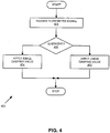
- FIG. 4 is a flowchart 400 of a method of removing noise from a flow meter signal according to an embodiment of the invention.
- a flow meter signal is received.
- the flow meter signal can be pre-processed in any manner, including normalization of the flow meter signal.
- step 402 if the flow meter signal is substantially quiescent, the method branches to step 403; otherwise the method branches to step 404.
- step 403 because the flow meter signal is substantially quiescent, a large damping value is applied to the flow meter signal. Because the flow meter signal is changing relatively slowly, a large amount of damping can be applied without affecting the flow meter data in the flow meter signal, and only the noise component of the flow meter signal is attenuated by the heavy damping.
- step 404 because the flow meter signal is experiencing large or rapid changes in value, a small damping value is applied to the flow meter signal. In this manner, the noise component of the flow meter signal is substantially removed but without affecting the flow meter data.
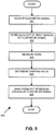
- FIG. 5 is a flowchart 500 of a method of removing noise from a flow meter signal according to another embodiment of the invention.
- step 501 a flow meter signal is received, as previously discussed.
- the flow meter data is substantially filtered out of a first version of the flow meter signal in order to obtain a substantially pure noise signal.
- the measurement can be performed in order to characterize the noise and dynamically damp the noise out of the flow meter signal.
- the data can be removed by a high pass or band-pass filter, as previously discussed.
- the noise is measured and noise characteristics are thereby obtained.
- the noise characteristics can include a maximum noise amplitude and a zero offset, as previously discussed. It should be understood that the noise characteristics are dynamic and can change over time. For example, the noise characteristics commonly vary when other flow meters are connected in the process line and therefore generating cross-talk noise. However, other noise sources are also contemplated, such as environmental noise from pumping equipment, for instance.
- a damping value is determined from the current noise characteristics.
- the damping value represents an amount of damping that will substantially remove the noise from the flow meter signal but without substantially impacting the flow meter signal.
- step 505 the damping value and the flow meter signal are inputted into a filter element 206 and the filter element 206 damps out the noise using the damping value.
- the damping can be ramped from a current damping value to a new damping value.
- FIG. 6 is a graph that illustrates damping removal of noise from a flow meter signal.
- the graph includes a flow meter signal 601 and a noise signal 602. It can be seen from the figure that when the noise signal 602 is damped out, the flow meter signal 601 can approximate a square wave.
- the filter system's response time changes to a very fast response time filter. During this time, the filtered signal will more closely resemble the original flow meter signal until eventually the filter system 200 reverts back to a heavily damped signal.
- FIG. 7 is a diagram of the damping adjuster 205 according to an embodiment of the invention.
- the damping adjuster 205 in this embodiment includes absolute value blocks 701 and 703, product blocks 702 and 706, switching blocks 704 and 710, unit delay blocks 705 and 712 (such as 1/Z unit delay blocks, for example), an interface 707, a damping value block 708, a relational operator block 709, and a damping delay coefficient block 711.
- the damping adjuster 205 includes the error, maximum noise, maximum flow value, and zero offset inputs as previously discussed, and outputs the damping value.
- the product block 702 divides the zero offset by the maximum flow value in order to generate a noise value.
- the noise value is representative of the average noise content and indicates the distance from the noise signal to zero. If this noise value is less than a predetermined quiescent threshold, then the noise level is determined to be substantially quiescent and is therefore accurate enough to be used in the damping value lookup block 708.
- the absolute value blocks 701 and 703 take the absolute values of their respective inputs.
- the absolute value block 703 outputs a positive noise value to the switching block 705.
- the absolute value block 701 outputs a positive error value to the interface 707.
- the switching block 704 receives the maximum noise value, the noise value, and a unit delay produced by the unit delay block 705.
- the switching block 704 is configured to output the noise value if the noise value is less than the maximum noise value, and output the maximum noise value otherwise.
- the switching block 704 can output the previous switch output (from the unit delay block 705) when not outputting either the noise value or the maximum noise value.
- the output of the switching block 704 is connected to the input of the unit delay block 705 and to the product block 706.
- the product block 706 also receives the noise value and the maximum flow value.
- the product block 706 divides the maximum flow value by the noise value in order to produce a normalized noise value that is outputted to the interface 707.
- the interface 707 passes the normalized error signal and the normalized noise signal to the damping value lookup block 708.
- the interface 707 in one embodiment multiplexes the normalized noise signal and the normalized error signal into a vector format, wherein the damping value lookup block 708 receives a single input.
- the damping value lookup block 708 generates the damping value from the normalized error and normalized noise inputs. In one embodiment, the damping value lookup block 708 performs a table lookup in order to obtain the damping value, such as Table 1, discussed in conjunction with FIG. 2 , above. The damping value lookup block 708 outputs the damping value to the relational operator block 709.
- the final stage of the damping adjuster 205 (i.e., the components 709-712) control the rate at which the damping value can be changed.
- the relational operator block 709 compares the new damping value (outputted by the damping value lookup block 708) to the current damping value available at the output of the damping adjuster 205.
- the relational operator block 709 generates a relational output that indicates whether the new damping value is smaller than the current damping value.
- the switching block 710 has as inputs the new damping value, the current damping value, and the relational output.
- the switching block 710 is configured to select and output either the new damping value or the current damping value, depending on the relational output. If the new damping value is smaller than the current damping value, then the switching block 710 feeds the new damping value directly to the output. However, if the new damping value is larger than the current damping value, then the switching block 710 channels the new damping value through the damping delay coefficient 711 and the unit delay 712 and ramps the damping value output from the current damping value to the new damping value by multiplying the new damping value by a delay coefficient. The switching block 710 outputs the selected damping value to the damping delay coefficient 711.
- the damping delay coefficient 711 defines a damping rate and controls how quickly the damping adjuster 205 can ramp to the new damping value.
- the damping delay coefficient 711 in one embodiment is a number slightly larger than one.
- the output of the damping delay coefficient 711 is inputted into the unit delay 712.
- the unit delay 712 delays the damping value by a predetermined delay period.
- the predetermined delay period can be a constant value, for example, or can be obtained from a table.
- the output of the unit delay 712 is the damping value output of the damping adjuster 205.
- the damping adjuster 205 therefore generates the damping value based on the noise characteristics and on the damping delay coefficient 711.
- FIG. 8 is a graph of various damping values that can be implemented in the flow meter filter system 200 according to an embodiment of the invention.
- the figure shows normalized flow rate over time for various damping values. It can be seen that a damping value can be selected not only based on the desired amount of damping, but on the time period required in order to achieve the desired noise damping. For example, a damping value of 1 has a much faster response than a damping value of 256.
- FIG. 9 is a graph that shows a ramping of the damping value according to an embodiment of the invention.
- the straight line 900 is a desired damping value
- the curve 901 is a damping value that is being ramped up over time.
- the ramping rate can be selected in order to ramp from a beginning point to the target damping value over a predetermined period of time.
- the flow meter filtering according to the invention enables noise to be filtered out of a flow meter signal, including cross-talk noise.
- the filtering is accomplished without degrading the flow meter data in the flow meter signal.
- the filtering accommodates data transitions in the flow meter data.
- a digital filter implementation accomplishes more optimal filtering, but with physically smaller components.
- the flow meter filter system 200 can be implemented in an Application Specific Integrated Circuit (ASIC), for example.
- ASIC Application Specific Integrated Circuit
- the digital filter can be dynamically controlled during operation.
- the filtering can be dynamically controlled according to noise conditions and according to flow conditions/levels. Therefore, the amount of damping can be changed in order to optimally remove noise without influencing the flow meter data signal.
- This is in contrast to an analog filtering scheme, wherein a fixed amount of filtering is performed.
- Such a fixed filtering scheme only works well when the data signal and the noise signal are predictable and well-behaved.
Landscapes
- Physics & Mathematics (AREA)
- Fluid Mechanics (AREA)
- General Physics & Mathematics (AREA)
- Engineering & Computer Science (AREA)
- Signal Processing (AREA)
- Measuring Volume Flow (AREA)
Applications Claiming Priority (1)
| Application Number | Priority Date | Filing Date | Title |
|---|---|---|---|
| PCT/US2003/027961 WO2005033634A1 (en) | 2003-09-05 | 2003-09-05 | Flow meter filter system and method |
Publications (2)
| Publication Number | Publication Date |
|---|---|
| EP1660844A1 EP1660844A1 (en) | 2006-05-31 |
| EP1660844B1 true EP1660844B1 (en) | 2017-03-15 |
Family
ID=34421179
Family Applications (1)
| Application Number | Title | Priority Date | Filing Date |
|---|---|---|---|
| EP03749480.4A Expired - Lifetime EP1660844B1 (en) | 2003-09-05 | 2003-09-05 | Flow meter filter system and method |
Country Status (12)
| Country | Link |
|---|---|
| US (2) | US7257495B2 (pt) |
| EP (1) | EP1660844B1 (pt) |
| JP (1) | JP4546926B2 (pt) |
| KR (4) | KR101380291B1 (pt) |
| CN (1) | CN100434869C (pt) |
| AR (1) | AR045508A1 (pt) |
| AU (1) | AU2003268513A1 (pt) |
| BR (2) | BRPI0318493B1 (pt) |
| CA (1) | CA2536341C (pt) |
| HK (1) | HK1096146A1 (pt) |
| MX (1) | MXPA06002319A (pt) |
| WO (1) | WO2005033634A1 (pt) |
Families Citing this family (21)
| Publication number | Priority date | Publication date | Assignee | Title |
|---|---|---|---|---|
| GB2455685B (en) | 2006-11-10 | 2011-03-23 | Rem Scient Entpr Inc | Rotating fluid measurement device and method |
| NL1034349C2 (nl) * | 2007-09-07 | 2009-03-10 | Berkin Bv | Coriolis type flow meetsysteem met analoog-digitaal omzetters met instelbare bemonsteringsfrequentie. |
| DE102007052047B4 (de) * | 2007-10-31 | 2014-06-26 | Abb Ag | Verfahren und Einrichtung zur Messung von Fremdkörpern im Messmedium |
| US8061216B2 (en) * | 2007-12-21 | 2011-11-22 | Bausch & Lomb Incorporated | Aspiration flow mesurement system with flow signal air bubble filter |
| KR101231080B1 (ko) * | 2008-07-30 | 2013-02-07 | 마이크로 모우션, 인코포레이티드 | 하나 이상의 디지털 필터들을 포함하는 프로세싱 시스템에서의 프로세서 동작의 최적화 |
| KR102471843B1 (ko) | 2014-09-30 | 2022-11-28 | 하이드릴 유에스에이 디스트리뷰션 엘엘씨 | 파열 방지기 제어를 위한 안정 무결성 기준(sil) 등급 시스템 |
| US10048673B2 (en) | 2014-10-17 | 2018-08-14 | Hydril Usa Distribution, Llc | High pressure blowout preventer system |
| US10196871B2 (en) | 2014-09-30 | 2019-02-05 | Hydril USA Distribution LLC | Sil rated system for blowout preventer control |
| US10876369B2 (en) | 2014-09-30 | 2020-12-29 | Hydril USA Distribution LLC | High pressure blowout preventer system |
| US9989975B2 (en) | 2014-11-11 | 2018-06-05 | Hydril Usa Distribution, Llc | Flow isolation for blowout preventer hydraulic control systems |
| WO2016085506A1 (en) * | 2014-11-26 | 2016-06-02 | Rem Scientific Enterprises, Inc | Systems and methods for reducing casing noise effects |
| US9759018B2 (en) | 2014-12-12 | 2017-09-12 | Hydril USA Distribution LLC | System and method of alignment for hydraulic coupling |
| US9528340B2 (en) | 2014-12-17 | 2016-12-27 | Hydrill USA Distribution LLC | Solenoid valve housings for blowout preventer |
| WO2016100663A1 (en) | 2014-12-17 | 2016-06-23 | Hydril USA Distribution LLC | Power and communications hub for interface between control pod, auxiliary subsea systems, and surface controls |
| US9828824B2 (en) * | 2015-05-01 | 2017-11-28 | Hydril Usa Distribution, Llc | Hydraulic re-configurable and subsea repairable control system for deepwater blow-out preventers |
| GB201514575D0 (en) * | 2015-08-17 | 2015-09-30 | Norgren Ltd C A | DC canceller adaptive filter for attenuating noise in a feedback path of a flow controller |
| US10267651B2 (en) * | 2015-12-28 | 2019-04-23 | Nudge Systems, LLC | Fluid flow sensing systems and methods of use |
| DE102018110456A1 (de) * | 2018-05-02 | 2019-11-07 | Endress + Hauser Flowtec Ag | Meßsystem sowie Verfahren zum Messen einer Meßgröße eines strömenden Fluids |
| MX2020014164A (es) * | 2018-07-30 | 2021-03-09 | Micro Motion Inc | Electronica de medidor y metodos de diagnostico de verificacion para medidor de flujo. |
| US11092470B2 (en) * | 2019-09-13 | 2021-08-17 | Micro Motion Inc. | Magnetic flowmeter with noise adaptive dead time |
| CN115298522A (zh) * | 2020-03-31 | 2022-11-04 | 恩德斯+豪斯流量技术股份有限公司 | 用于操作科里奥利测量设备的方法 |
Family Cites Families (28)
| Publication number | Priority date | Publication date | Assignee | Title |
|---|---|---|---|---|
| US4303980A (en) * | 1979-12-03 | 1981-12-01 | Fischer & Porter Company | Electromagnetic flowmeter system having automatically adjusted response characteristics |
| JPS6166123A (ja) * | 1984-09-07 | 1986-04-04 | Toshiba Corp | 電磁流量計変換器 |
| JP2832944B2 (ja) * | 1988-06-10 | 1998-12-09 | 株式会社日立製作所 | 計測データの遅れ補償方法 |
| US4934196A (en) * | 1989-06-02 | 1990-06-19 | Micro Motion, Inc. | Coriolis mass flow rate meter having a substantially increased noise immunity |
| US4996871A (en) * | 1989-06-02 | 1991-03-05 | Micro Motion, Inc. | Coriolis densimeter having substantially increased noise immunity |
| US5009109A (en) * | 1989-12-06 | 1991-04-23 | Micro Motion, Inc. | Flow tube drive circuit having a bursty output for use in a coriolis meter |
| US5388465A (en) * | 1992-11-17 | 1995-02-14 | Yamatake-Honeywell Co., Ltd. | Electromagnetic flowmeter |
| US5550537A (en) * | 1994-05-06 | 1996-08-27 | Endress + Hauser, Inc. | Apparatus and method for measuring mass flow rate of a moving medium |
| US5555190A (en) * | 1995-07-12 | 1996-09-10 | Micro Motion, Inc. | Method and apparatus for adaptive line enhancement in Coriolis mass flow meter measurement |
| US5907104A (en) * | 1995-12-08 | 1999-05-25 | Direct Measurement Corporation | Signal processing and field proving methods and circuits for a coriolis mass flow meter |
| US5926096A (en) * | 1996-03-11 | 1999-07-20 | The Foxboro Company | Method and apparatus for correcting for performance degrading factors in a coriolis-type mass flowmeter |
| US6601005B1 (en) * | 1996-11-07 | 2003-07-29 | Rosemount Inc. | Process device diagnostics using process variable sensor signal |
| JPH1186180A (ja) * | 1997-09-10 | 1999-03-30 | Toshiba Corp | センサ信号伝送装置及びそれに用いるノイズフィルタ |
| JP3658975B2 (ja) * | 1998-02-20 | 2005-06-15 | 富士電機システムズ株式会社 | 電磁流量計 |
| NL1008827C1 (nl) | 1998-04-07 | 1999-10-08 | Nico Roosnek | Werkwijze en inrichting voor het meten van fysische parameters. |
| US6594613B1 (en) * | 1998-12-10 | 2003-07-15 | Rosemount Inc. | Adjustable bandwidth filter for process variable transmitter |
| ATE510189T1 (de) * | 1999-04-01 | 2011-06-15 | Panametrics | Aufsteckbarer ultraschall-durchflussaufnehmer für flüssigkeiten niedriger dichte |
| JP3469125B2 (ja) * | 1999-04-13 | 2003-11-25 | 株式会社山武 | 電磁流量計 |
| JP3562379B2 (ja) * | 1999-04-14 | 2004-09-08 | 松下電器産業株式会社 | 流量計 |
| US6502466B1 (en) * | 1999-06-29 | 2003-01-07 | Direct Measurement Corporation | System and method for fluid compressibility compensation in a Coriolis mass flow meter |
| DE01918944T1 (de) * | 2000-03-23 | 2004-10-21 | Invensys Systems, Inc., Foxboro | Korrektur für eine zweiphasenströmung in einem digitalen durchflussmesser |
| US6505135B2 (en) * | 2001-03-13 | 2003-01-07 | Micro Motion, Inc. | Initialization algorithm for drive control in a coriolis flowmeter |
| US6590167B2 (en) * | 2001-03-30 | 2003-07-08 | Ethicon, Inc. | Digital filter for fluid scale |
| EP1393020A1 (en) * | 2001-04-27 | 2004-03-03 | Mykrolis Corporation | System and method for filtering output in mass flow controllers and mass flow meters |
| GB2380798A (en) * | 2001-07-02 | 2003-04-16 | Abb Automation Ltd | Electromagnetic flowmeter |
| US20040123666A1 (en) * | 2002-12-31 | 2004-07-01 | Ao Xiaolei S. | Ultrasonic damping material |
| US7299705B2 (en) * | 2003-07-15 | 2007-11-27 | Cidra Corporation | Apparatus and method for augmenting a Coriolis meter |
| CN100447535C (zh) * | 2003-10-30 | 2008-12-31 | 因万西斯系统股份有限公司 | 流量计的动态响应特性 |
-
2003
- 2003-09-05 KR KR1020117027722A patent/KR101380291B1/ko active IP Right Grant
- 2003-09-05 AU AU2003268513A patent/AU2003268513A1/en not_active Abandoned
- 2003-09-05 CN CNB038270358A patent/CN100434869C/zh not_active Expired - Lifetime
- 2003-09-05 KR KR1020107006401A patent/KR20100035189A/ko active Search and Examination
- 2003-09-05 WO PCT/US2003/027961 patent/WO2005033634A1/en active Application Filing
- 2003-09-05 KR KR1020067004567A patent/KR101014314B1/ko active IP Right Grant
- 2003-09-05 BR BRPI0318493-5A patent/BRPI0318493B1/pt unknown
- 2003-09-05 MX MXPA06002319A patent/MXPA06002319A/es active IP Right Grant
- 2003-09-05 EP EP03749480.4A patent/EP1660844B1/en not_active Expired - Lifetime
- 2003-09-05 US US10/568,861 patent/US7257495B2/en not_active Expired - Lifetime
- 2003-09-05 CA CA2536341A patent/CA2536341C/en not_active Expired - Lifetime
- 2003-09-05 JP JP2005509375A patent/JP4546926B2/ja not_active Expired - Fee Related
- 2003-09-05 KR KR1020107026574A patent/KR20100127321A/ko not_active Application Discontinuation
- 2003-09-05 BR BRPI0318493-5A patent/BR0318493A/pt active IP Right Grant
-
2004
- 2004-08-26 AR ARP040103070A patent/AR045508A1/es unknown
-
2007
- 2007-03-26 HK HK07103204.9A patent/HK1096146A1/xx not_active IP Right Cessation
- 2007-06-25 US US11/767,615 patent/US7558684B2/en not_active Expired - Lifetime
Non-Patent Citations (1)
| Title |
|---|
| None * |
Also Published As
| Publication number | Publication date |
|---|---|
| CA2536341A1 (en) | 2005-04-14 |
| US7558684B2 (en) | 2009-07-07 |
| KR20100035189A (ko) | 2010-04-02 |
| BR0318493A (pt) | 2006-09-12 |
| KR101380291B1 (ko) | 2014-04-01 |
| EP1660844A1 (en) | 2006-05-31 |
| JP2007521466A (ja) | 2007-08-02 |
| CA2536341C (en) | 2012-11-27 |
| CN1839295A (zh) | 2006-09-27 |
| AR045508A1 (es) | 2005-11-02 |
| CN100434869C (zh) | 2008-11-19 |
| MXPA06002319A (es) | 2006-05-19 |
| KR20100127321A (ko) | 2010-12-03 |
| US20070262814A1 (en) | 2007-11-15 |
| WO2005033634A1 (en) | 2005-04-14 |
| US7257495B2 (en) | 2007-08-14 |
| KR20110129989A (ko) | 2011-12-02 |
| JP4546926B2 (ja) | 2010-09-22 |
| KR101014314B1 (ko) | 2011-02-16 |
| HK1096146A1 (en) | 2007-05-25 |
| KR20060092210A (ko) | 2006-08-22 |
| AU2003268513A1 (en) | 2005-04-21 |
| US20060265168A1 (en) | 2006-11-23 |
| BRPI0318493B1 (pt) | 2018-07-03 |
Similar Documents
| Publication | Publication Date | Title |
|---|---|---|
| US7558684B2 (en) | Flow meter filter system and method | |
| US5576497A (en) | Adaptive filtering for a vortex flowmeter | |
| US6774822B1 (en) | Method and systems for filtering unwanted noise in a material metering machine | |
| AU4381297A (en) | Method and device for measuring the volumetric flow of a fluid | |
| JP5570787B2 (ja) | 流量計フィルタ・システム及び方法 | |
| RU2319113C2 (ru) | Система фильтра расходомера и способ удаления шума из сигнала расходомера (варианты) | |
| AU2008360010B2 (en) | Optimizing processor operation in a processing system including one or more digital filters | |
| CN101696889B (zh) | 从流量计信号中除去噪声的方法 | |
| EP0612149B1 (en) | Method for adjusting an adaptive exponential filter and adaptive exponential filter | |
| WO2018231227A1 (en) | A notch filter in a vibratory flow meter | |
| JPS60114723A (ja) | 測定装置 | |
| WO2024058768A1 (en) | Determining a viscosity of a fluid | |
| JP2005189030A (ja) | サンプリング式測定装置 | |
| JP2902233B2 (ja) | 流量補正装置 | |
| SU930273A1 (ru) | Устройство дл определени параметров колебательных систем | |
| SU1649278A1 (ru) | Способ определени расхода газа и устройство дл его осуществлени | |
| RU1795287C (ru) | Способ определени массового расхода газа | |
| AU2013205299A1 (en) | Optimizing processor operation in a processing system including one or more digital filters |
Legal Events
| Date | Code | Title | Description |
|---|---|---|---|
| PUAI | Public reference made under article 153(3) epc to a published international application that has entered the european phase |
Free format text: ORIGINAL CODE: 0009012 |
|
| 17P | Request for examination filed |
Effective date: 20060220 |
|
| AK | Designated contracting states |
Kind code of ref document: A1 Designated state(s): CH DE FR GB LI |
|
| DAX | Request for extension of the european patent (deleted) | ||
| RBV | Designated contracting states (corrected) |
Designated state(s): CH DE FR GB LI |
|
| 17Q | First examination report despatched |
Effective date: 20061212 |
|
| REG | Reference to a national code |
Ref country code: DE Ref legal event code: R079 Ref document number: 60350001 Country of ref document: DE Free format text: PREVIOUS MAIN CLASS: G01F0001000000 Ipc: G01F0025000000 |
|
| RIC1 | Information provided on ipc code assigned before grant |
Ipc: G01F 25/00 20060101AFI20160715BHEP Ipc: G01F 15/00 20060101ALI20160715BHEP Ipc: G01F 15/06 20060101ALI20160715BHEP Ipc: G01F 1/00 20060101ALI20160715BHEP Ipc: G01F 1/84 20060101ALI20160715BHEP |
|
| GRAP | Despatch of communication of intention to grant a patent |
Free format text: ORIGINAL CODE: EPIDOSNIGR1 |
|
| INTG | Intention to grant announced |
Effective date: 20160929 |
|
| GRAS | Grant fee paid |
Free format text: ORIGINAL CODE: EPIDOSNIGR3 |
|
| GRAA | (expected) grant |
Free format text: ORIGINAL CODE: 0009210 |
|
| AK | Designated contracting states |
Kind code of ref document: B1 Designated state(s): CH DE FR GB LI |
|
| REG | Reference to a national code |
Ref country code: CH Ref legal event code: EP Ref country code: GB Ref legal event code: FG4D |
|
| REG | Reference to a national code |
Ref country code: DE Ref legal event code: R096 Ref document number: 60350001 Country of ref document: DE |
|
| REG | Reference to a national code |
Ref country code: CH Ref legal event code: NV Representative=s name: VOSSIUS AND PARTNER PATENTANWAELTE RECHTSANWAE, CH |
|
| REG | Reference to a national code |
Ref country code: FR Ref legal event code: PLFP Year of fee payment: 15 |
|
| REG | Reference to a national code |
Ref country code: DE Ref legal event code: R097 Ref document number: 60350001 Country of ref document: DE |
|
| PLBE | No opposition filed within time limit |
Free format text: ORIGINAL CODE: 0009261 |
|
| STAA | Information on the status of an ep patent application or granted ep patent |
Free format text: STATUS: NO OPPOSITION FILED WITHIN TIME LIMIT |
|
| 26N | No opposition filed |
Effective date: 20171218 |
|
| REG | Reference to a national code |
Ref country code: FR Ref legal event code: PLFP Year of fee payment: 16 |
|
| PGFP | Annual fee paid to national office [announced via postgrant information from national office to epo] |
Ref country code: GB Payment date: 20220818 Year of fee payment: 20 Ref country code: DE Payment date: 20220818 Year of fee payment: 20 |
|
| PGFP | Annual fee paid to national office [announced via postgrant information from national office to epo] |
Ref country code: FR Payment date: 20220819 Year of fee payment: 20 |
|
| PGFP | Annual fee paid to national office [announced via postgrant information from national office to epo] |
Ref country code: CH Payment date: 20221001 Year of fee payment: 20 |
|
| P01 | Opt-out of the competence of the unified patent court (upc) registered |
Effective date: 20230522 |
|
| REG | Reference to a national code |
Ref country code: DE Ref legal event code: R071 Ref document number: 60350001 Country of ref document: DE |
|
| REG | Reference to a national code |
Ref country code: CH Ref legal event code: PL |
|
| REG | Reference to a national code |
Ref country code: GB Ref legal event code: PE20 Expiry date: 20230904 |
|
| PG25 | Lapsed in a contracting state [announced via postgrant information from national office to epo] |
Ref country code: GB Free format text: LAPSE BECAUSE OF EXPIRATION OF PROTECTION Effective date: 20230904 |