EP1659331B1 - High-performance pressure vessel and carbon fiber for pressure vessel - Google Patents
High-performance pressure vessel and carbon fiber for pressure vessel Download PDFInfo
- Publication number
- EP1659331B1 EP1659331B1 EP04772663.3A EP04772663A EP1659331B1 EP 1659331 B1 EP1659331 B1 EP 1659331B1 EP 04772663 A EP04772663 A EP 04772663A EP 1659331 B1 EP1659331 B1 EP 1659331B1
- Authority
- EP
- European Patent Office
- Prior art keywords
- pressure
- vessel
- fiber
- pressure vessel
- reinforced plastic
- Prior art date
- Legal status (The legal status is an assumption and is not a legal conclusion. Google has not performed a legal analysis and makes no representation as to the accuracy of the status listed.)
- Active
Links
- 229920000049 Carbon (fiber) Polymers 0.000 title description 42
- 239000004917 carbon fiber Substances 0.000 title description 42
- VNWKTOKETHGBQD-UHFFFAOYSA-N methane Chemical compound C VNWKTOKETHGBQD-UHFFFAOYSA-N 0.000 title description 25
- 239000012783 reinforcing fiber Substances 0.000 claims description 89
- 229920002430 Fibre-reinforced plastic Polymers 0.000 claims description 81
- 239000011151 fibre-reinforced plastic Substances 0.000 claims description 81
- 229920003023 plastic Polymers 0.000 claims description 27
- 239000004033 plastic Substances 0.000 claims description 27
- OKTJSMMVPCPJKN-UHFFFAOYSA-N Carbon Chemical compound [C] OKTJSMMVPCPJKN-UHFFFAOYSA-N 0.000 claims description 12
- 229910052799 carbon Inorganic materials 0.000 claims description 12
- 229910052751 metal Inorganic materials 0.000 claims description 8
- 239000002184 metal Substances 0.000 claims description 8
- 239000010410 layer Substances 0.000 description 99
- 239000000835 fiber Substances 0.000 description 36
- 230000009172 bursting Effects 0.000 description 28
- 238000000034 method Methods 0.000 description 27
- 238000005259 measurement Methods 0.000 description 14
- 238000004519 manufacturing process Methods 0.000 description 13
- 239000011159 matrix material Substances 0.000 description 13
- 238000010438 heat treatment Methods 0.000 description 11
- 239000000463 material Substances 0.000 description 11
- 238000012360 testing method Methods 0.000 description 11
- 239000000523 sample Substances 0.000 description 9
- 238000003860 storage Methods 0.000 description 9
- 230000000052 comparative effect Effects 0.000 description 7
- 239000002243 precursor Substances 0.000 description 7
- 229920000297 Rayon Polymers 0.000 description 6
- 239000007789 gas Substances 0.000 description 6
- 239000013585 weight reducing agent Substances 0.000 description 6
- 238000004804 winding Methods 0.000 description 6
- 238000010000 carbonizing Methods 0.000 description 5
- 239000002131 composite material Substances 0.000 description 5
- 230000007423 decrease Effects 0.000 description 5
- 229920000647 polyepoxide Polymers 0.000 description 5
- 238000011156 evaluation Methods 0.000 description 4
- 239000000243 solution Substances 0.000 description 4
- 238000009987 spinning Methods 0.000 description 4
- 230000009466 transformation Effects 0.000 description 4
- 229910000831 Steel Inorganic materials 0.000 description 3
- 230000015271 coagulation Effects 0.000 description 3
- 238000005345 coagulation Methods 0.000 description 3
- 239000003822 epoxy resin Substances 0.000 description 3
- 239000003733 fiber-reinforced composite Substances 0.000 description 3
- 238000009730 filament winding Methods 0.000 description 3
- 239000000446 fuel Substances 0.000 description 3
- WFKAJVHLWXSISD-UHFFFAOYSA-N isobutyramide Chemical compound CC(C)C(N)=O WFKAJVHLWXSISD-UHFFFAOYSA-N 0.000 description 3
- 239000000203 mixture Substances 0.000 description 3
- 239000010959 steel Substances 0.000 description 3
- KUBDPQJOLOUJRM-UHFFFAOYSA-N 2-(chloromethyl)oxirane;4-[2-(4-hydroxyphenyl)propan-2-yl]phenol Chemical compound ClCC1CO1.C=1C=C(O)C=CC=1C(C)(C)C1=CC=C(O)C=C1 KUBDPQJOLOUJRM-UHFFFAOYSA-N 0.000 description 2
- 229910000838 Al alloy Inorganic materials 0.000 description 2
- UFHFLCQGNIYNRP-UHFFFAOYSA-N Hydrogen Chemical compound [H][H] UFHFLCQGNIYNRP-UHFFFAOYSA-N 0.000 description 2
- XEEYBQQBJWHFJM-UHFFFAOYSA-N Iron Chemical compound [Fe] XEEYBQQBJWHFJM-UHFFFAOYSA-N 0.000 description 2
- 229910052581 Si3N4 Inorganic materials 0.000 description 2
- 229910052782 aluminium Inorganic materials 0.000 description 2
- XAGFODPZIPBFFR-UHFFFAOYSA-N aluminium Chemical compound [Al] XAGFODPZIPBFFR-UHFFFAOYSA-N 0.000 description 2
- 239000007864 aqueous solution Substances 0.000 description 2
- 230000015572 biosynthetic process Effects 0.000 description 2
- 150000001875 compounds Chemical class 0.000 description 2
- 239000001257 hydrogen Substances 0.000 description 2
- 229910052739 hydrogen Inorganic materials 0.000 description 2
- 229920005989 resin Polymers 0.000 description 2
- 239000011347 resin Substances 0.000 description 2
- HQVNEWCFYHHQES-UHFFFAOYSA-N silicon nitride Chemical compound N12[Si]34N5[Si]62N3[Si]51N64 HQVNEWCFYHHQES-UHFFFAOYSA-N 0.000 description 2
- LXKCHCXZBPLTAE-UHFFFAOYSA-N 3,4-dimethyl-1H-pyrazole phosphate Chemical compound OP(O)(O)=O.CC1=CNN=C1C LXKCHCXZBPLTAE-UHFFFAOYSA-N 0.000 description 1
- 229920000178 Acrylic resin Polymers 0.000 description 1
- 239000004925 Acrylic resin Substances 0.000 description 1
- ZOXJGFHDIHLPTG-UHFFFAOYSA-N Boron Chemical compound [B] ZOXJGFHDIHLPTG-UHFFFAOYSA-N 0.000 description 1
- 239000004593 Epoxy Substances 0.000 description 1
- 229910000861 Mg alloy Inorganic materials 0.000 description 1
- 229920002025 Pluronic® F 88 Polymers 0.000 description 1
- RVGRUAULSDPKGF-UHFFFAOYSA-N Poloxamer Chemical compound C1CO1.CC1CO1 RVGRUAULSDPKGF-UHFFFAOYSA-N 0.000 description 1
- XUIMIQQOPSSXEZ-UHFFFAOYSA-N Silicon Chemical compound [Si] XUIMIQQOPSSXEZ-UHFFFAOYSA-N 0.000 description 1
- QVGXLLKOCUKJST-UHFFFAOYSA-N atomic oxygen Chemical compound [O] QVGXLLKOCUKJST-UHFFFAOYSA-N 0.000 description 1
- 229910052796 boron Inorganic materials 0.000 description 1
- 239000003795 chemical substances by application Substances 0.000 description 1
- 239000000470 constituent Substances 0.000 description 1
- 230000008602 contraction Effects 0.000 description 1
- 230000007812 deficiency Effects 0.000 description 1
- 239000003995 emulsifying agent Substances 0.000 description 1
- 239000002828 fuel tank Substances 0.000 description 1
- 239000003365 glass fiber Substances 0.000 description 1
- 229920001903 high density polyethylene Polymers 0.000 description 1
- 239000004700 high-density polyethylene Substances 0.000 description 1
- 239000011261 inert gas Substances 0.000 description 1
- 229910052742 iron Inorganic materials 0.000 description 1
- 239000003921 oil Substances 0.000 description 1
- 230000003647 oxidation Effects 0.000 description 1
- 238000007254 oxidation reaction Methods 0.000 description 1
- 230000001590 oxidative effect Effects 0.000 description 1
- 239000001301 oxygen Substances 0.000 description 1
- 229910052760 oxygen Inorganic materials 0.000 description 1
- 239000005011 phenolic resin Substances 0.000 description 1
- 229920002239 polyacrylonitrile Polymers 0.000 description 1
- 230000003014 reinforcing effect Effects 0.000 description 1
- 230000035939 shock Effects 0.000 description 1
- 229910052710 silicon Inorganic materials 0.000 description 1
- 239000010703 silicon Substances 0.000 description 1
- 239000002356 single layer Substances 0.000 description 1
- 238000004513 sizing Methods 0.000 description 1
- 238000006557 surface reaction Methods 0.000 description 1
- 229920001567 vinyl ester resin Polymers 0.000 description 1
- 239000002699 waste material Substances 0.000 description 1
- 238000002166 wet spinning Methods 0.000 description 1
Images

Classifications
-
- F—MECHANICAL ENGINEERING; LIGHTING; HEATING; WEAPONS; BLASTING
- F17—STORING OR DISTRIBUTING GASES OR LIQUIDS
- F17C—VESSELS FOR CONTAINING OR STORING COMPRESSED, LIQUEFIED OR SOLIDIFIED GASES; FIXED-CAPACITY GAS-HOLDERS; FILLING VESSELS WITH, OR DISCHARGING FROM VESSELS, COMPRESSED, LIQUEFIED, OR SOLIDIFIED GASES
- F17C1/00—Pressure vessels, e.g. gas cylinder, gas tank, replaceable cartridge
- F17C1/16—Pressure vessels, e.g. gas cylinder, gas tank, replaceable cartridge constructed of plastics materials
-
- F—MECHANICAL ENGINEERING; LIGHTING; HEATING; WEAPONS; BLASTING
- F17—STORING OR DISTRIBUTING GASES OR LIQUIDS
- F17C—VESSELS FOR CONTAINING OR STORING COMPRESSED, LIQUEFIED OR SOLIDIFIED GASES; FIXED-CAPACITY GAS-HOLDERS; FILLING VESSELS WITH, OR DISCHARGING FROM VESSELS, COMPRESSED, LIQUEFIED, OR SOLIDIFIED GASES
- F17C1/00—Pressure vessels, e.g. gas cylinder, gas tank, replaceable cartridge
- F17C1/02—Pressure vessels, e.g. gas cylinder, gas tank, replaceable cartridge involving reinforcing arrangements
- F17C1/04—Protecting sheathings
- F17C1/06—Protecting sheathings built-up from wound-on bands or filamentary material, e.g. wires
-
- F—MECHANICAL ENGINEERING; LIGHTING; HEATING; WEAPONS; BLASTING
- F17—STORING OR DISTRIBUTING GASES OR LIQUIDS
- F17C—VESSELS FOR CONTAINING OR STORING COMPRESSED, LIQUEFIED OR SOLIDIFIED GASES; FIXED-CAPACITY GAS-HOLDERS; FILLING VESSELS WITH, OR DISCHARGING FROM VESSELS, COMPRESSED, LIQUEFIED, OR SOLIDIFIED GASES
- F17C2201/00—Vessel construction, in particular geometry, arrangement or size
- F17C2201/01—Shape
- F17C2201/0104—Shape cylindrical
- F17C2201/0109—Shape cylindrical with exteriorly curved end-piece
-
- F—MECHANICAL ENGINEERING; LIGHTING; HEATING; WEAPONS; BLASTING
- F17—STORING OR DISTRIBUTING GASES OR LIQUIDS
- F17C—VESSELS FOR CONTAINING OR STORING COMPRESSED, LIQUEFIED OR SOLIDIFIED GASES; FIXED-CAPACITY GAS-HOLDERS; FILLING VESSELS WITH, OR DISCHARGING FROM VESSELS, COMPRESSED, LIQUEFIED, OR SOLIDIFIED GASES
- F17C2201/00—Vessel construction, in particular geometry, arrangement or size
- F17C2201/05—Size
- F17C2201/056—Small (<1 m3)
-
- F—MECHANICAL ENGINEERING; LIGHTING; HEATING; WEAPONS; BLASTING
- F17—STORING OR DISTRIBUTING GASES OR LIQUIDS
- F17C—VESSELS FOR CONTAINING OR STORING COMPRESSED, LIQUEFIED OR SOLIDIFIED GASES; FIXED-CAPACITY GAS-HOLDERS; FILLING VESSELS WITH, OR DISCHARGING FROM VESSELS, COMPRESSED, LIQUEFIED, OR SOLIDIFIED GASES
- F17C2203/00—Vessel construction, in particular walls or details thereof
- F17C2203/06—Materials for walls or layers thereof; Properties or structures of walls or their materials
- F17C2203/0602—Wall structures; Special features thereof
- F17C2203/0604—Liners
-
- F—MECHANICAL ENGINEERING; LIGHTING; HEATING; WEAPONS; BLASTING
- F17—STORING OR DISTRIBUTING GASES OR LIQUIDS
- F17C—VESSELS FOR CONTAINING OR STORING COMPRESSED, LIQUEFIED OR SOLIDIFIED GASES; FIXED-CAPACITY GAS-HOLDERS; FILLING VESSELS WITH, OR DISCHARGING FROM VESSELS, COMPRESSED, LIQUEFIED, OR SOLIDIFIED GASES
- F17C2203/00—Vessel construction, in particular walls or details thereof
- F17C2203/06—Materials for walls or layers thereof; Properties or structures of walls or their materials
- F17C2203/0602—Wall structures; Special features thereof
- F17C2203/0612—Wall structures
- F17C2203/0614—Single wall
- F17C2203/0619—Single wall with two layers
-
- F—MECHANICAL ENGINEERING; LIGHTING; HEATING; WEAPONS; BLASTING
- F17—STORING OR DISTRIBUTING GASES OR LIQUIDS
- F17C—VESSELS FOR CONTAINING OR STORING COMPRESSED, LIQUEFIED OR SOLIDIFIED GASES; FIXED-CAPACITY GAS-HOLDERS; FILLING VESSELS WITH, OR DISCHARGING FROM VESSELS, COMPRESSED, LIQUEFIED, OR SOLIDIFIED GASES
- F17C2203/00—Vessel construction, in particular walls or details thereof
- F17C2203/06—Materials for walls or layers thereof; Properties or structures of walls or their materials
- F17C2203/0602—Wall structures; Special features thereof
- F17C2203/0612—Wall structures
- F17C2203/0614—Single wall
- F17C2203/0621—Single wall with three layers
-
- F—MECHANICAL ENGINEERING; LIGHTING; HEATING; WEAPONS; BLASTING
- F17—STORING OR DISTRIBUTING GASES OR LIQUIDS
- F17C—VESSELS FOR CONTAINING OR STORING COMPRESSED, LIQUEFIED OR SOLIDIFIED GASES; FIXED-CAPACITY GAS-HOLDERS; FILLING VESSELS WITH, OR DISCHARGING FROM VESSELS, COMPRESSED, LIQUEFIED, OR SOLIDIFIED GASES
- F17C2203/00—Vessel construction, in particular walls or details thereof
- F17C2203/06—Materials for walls or layers thereof; Properties or structures of walls or their materials
- F17C2203/0602—Wall structures; Special features thereof
- F17C2203/0612—Wall structures
- F17C2203/0614—Single wall
- F17C2203/0624—Single wall with four or more layers
-
- F—MECHANICAL ENGINEERING; LIGHTING; HEATING; WEAPONS; BLASTING
- F17—STORING OR DISTRIBUTING GASES OR LIQUIDS
- F17C—VESSELS FOR CONTAINING OR STORING COMPRESSED, LIQUEFIED OR SOLIDIFIED GASES; FIXED-CAPACITY GAS-HOLDERS; FILLING VESSELS WITH, OR DISCHARGING FROM VESSELS, COMPRESSED, LIQUEFIED, OR SOLIDIFIED GASES
- F17C2203/00—Vessel construction, in particular walls or details thereof
- F17C2203/06—Materials for walls or layers thereof; Properties or structures of walls or their materials
- F17C2203/0634—Materials for walls or layers thereof
- F17C2203/0636—Metals
- F17C2203/0646—Aluminium
-
- F—MECHANICAL ENGINEERING; LIGHTING; HEATING; WEAPONS; BLASTING
- F17—STORING OR DISTRIBUTING GASES OR LIQUIDS
- F17C—VESSELS FOR CONTAINING OR STORING COMPRESSED, LIQUEFIED OR SOLIDIFIED GASES; FIXED-CAPACITY GAS-HOLDERS; FILLING VESSELS WITH, OR DISCHARGING FROM VESSELS, COMPRESSED, LIQUEFIED, OR SOLIDIFIED GASES
- F17C2203/00—Vessel construction, in particular walls or details thereof
- F17C2203/06—Materials for walls or layers thereof; Properties or structures of walls or their materials
- F17C2203/0634—Materials for walls or layers thereof
- F17C2203/0636—Metals
- F17C2203/0648—Alloys or compositions of metals
-
- F—MECHANICAL ENGINEERING; LIGHTING; HEATING; WEAPONS; BLASTING
- F17—STORING OR DISTRIBUTING GASES OR LIQUIDS
- F17C—VESSELS FOR CONTAINING OR STORING COMPRESSED, LIQUEFIED OR SOLIDIFIED GASES; FIXED-CAPACITY GAS-HOLDERS; FILLING VESSELS WITH, OR DISCHARGING FROM VESSELS, COMPRESSED, LIQUEFIED, OR SOLIDIFIED GASES
- F17C2203/00—Vessel construction, in particular walls or details thereof
- F17C2203/06—Materials for walls or layers thereof; Properties or structures of walls or their materials
- F17C2203/0634—Materials for walls or layers thereof
- F17C2203/0658—Synthetics
- F17C2203/066—Plastics
-
- F—MECHANICAL ENGINEERING; LIGHTING; HEATING; WEAPONS; BLASTING
- F17—STORING OR DISTRIBUTING GASES OR LIQUIDS
- F17C—VESSELS FOR CONTAINING OR STORING COMPRESSED, LIQUEFIED OR SOLIDIFIED GASES; FIXED-CAPACITY GAS-HOLDERS; FILLING VESSELS WITH, OR DISCHARGING FROM VESSELS, COMPRESSED, LIQUEFIED, OR SOLIDIFIED GASES
- F17C2203/00—Vessel construction, in particular walls or details thereof
- F17C2203/06—Materials for walls or layers thereof; Properties or structures of walls or their materials
- F17C2203/0634—Materials for walls or layers thereof
- F17C2203/0658—Synthetics
- F17C2203/0663—Synthetics in form of fibers or filaments
- F17C2203/0665—Synthetics in form of fibers or filaments radially wound
-
- F—MECHANICAL ENGINEERING; LIGHTING; HEATING; WEAPONS; BLASTING
- F17—STORING OR DISTRIBUTING GASES OR LIQUIDS
- F17C—VESSELS FOR CONTAINING OR STORING COMPRESSED, LIQUEFIED OR SOLIDIFIED GASES; FIXED-CAPACITY GAS-HOLDERS; FILLING VESSELS WITH, OR DISCHARGING FROM VESSELS, COMPRESSED, LIQUEFIED, OR SOLIDIFIED GASES
- F17C2203/00—Vessel construction, in particular walls or details thereof
- F17C2203/06—Materials for walls or layers thereof; Properties or structures of walls or their materials
- F17C2203/0634—Materials for walls or layers thereof
- F17C2203/0658—Synthetics
- F17C2203/0663—Synthetics in form of fibers or filaments
- F17C2203/0668—Synthetics in form of fibers or filaments axially wound
-
- F—MECHANICAL ENGINEERING; LIGHTING; HEATING; WEAPONS; BLASTING
- F17—STORING OR DISTRIBUTING GASES OR LIQUIDS
- F17C—VESSELS FOR CONTAINING OR STORING COMPRESSED, LIQUEFIED OR SOLIDIFIED GASES; FIXED-CAPACITY GAS-HOLDERS; FILLING VESSELS WITH, OR DISCHARGING FROM VESSELS, COMPRESSED, LIQUEFIED, OR SOLIDIFIED GASES
- F17C2203/00—Vessel construction, in particular walls or details thereof
- F17C2203/06—Materials for walls or layers thereof; Properties or structures of walls or their materials
- F17C2203/0634—Materials for walls or layers thereof
- F17C2203/0658—Synthetics
- F17C2203/0663—Synthetics in form of fibers or filaments
- F17C2203/0673—Polymers
-
- F—MECHANICAL ENGINEERING; LIGHTING; HEATING; WEAPONS; BLASTING
- F17—STORING OR DISTRIBUTING GASES OR LIQUIDS
- F17C—VESSELS FOR CONTAINING OR STORING COMPRESSED, LIQUEFIED OR SOLIDIFIED GASES; FIXED-CAPACITY GAS-HOLDERS; FILLING VESSELS WITH, OR DISCHARGING FROM VESSELS, COMPRESSED, LIQUEFIED, OR SOLIDIFIED GASES
- F17C2209/00—Vessel construction, in particular methods of manufacturing
- F17C2209/21—Shaping processes
- F17C2209/2154—Winding
-
- F—MECHANICAL ENGINEERING; LIGHTING; HEATING; WEAPONS; BLASTING
- F17—STORING OR DISTRIBUTING GASES OR LIQUIDS
- F17C—VESSELS FOR CONTAINING OR STORING COMPRESSED, LIQUEFIED OR SOLIDIFIED GASES; FIXED-CAPACITY GAS-HOLDERS; FILLING VESSELS WITH, OR DISCHARGING FROM VESSELS, COMPRESSED, LIQUEFIED, OR SOLIDIFIED GASES
- F17C2209/00—Vessel construction, in particular methods of manufacturing
- F17C2209/23—Manufacturing of particular parts or at special locations
- F17C2209/232—Manufacturing of particular parts or at special locations of walls
-
- F—MECHANICAL ENGINEERING; LIGHTING; HEATING; WEAPONS; BLASTING
- F17—STORING OR DISTRIBUTING GASES OR LIQUIDS
- F17C—VESSELS FOR CONTAINING OR STORING COMPRESSED, LIQUEFIED OR SOLIDIFIED GASES; FIXED-CAPACITY GAS-HOLDERS; FILLING VESSELS WITH, OR DISCHARGING FROM VESSELS, COMPRESSED, LIQUEFIED, OR SOLIDIFIED GASES
- F17C2223/00—Handled fluid before transfer, i.e. state of fluid when stored in the vessel or before transfer from the vessel
- F17C2223/01—Handled fluid before transfer, i.e. state of fluid when stored in the vessel or before transfer from the vessel characterised by the phase
- F17C2223/0107—Single phase
- F17C2223/0123—Single phase gaseous, e.g. CNG, GNC
-
- F—MECHANICAL ENGINEERING; LIGHTING; HEATING; WEAPONS; BLASTING
- F17—STORING OR DISTRIBUTING GASES OR LIQUIDS
- F17C—VESSELS FOR CONTAINING OR STORING COMPRESSED, LIQUEFIED OR SOLIDIFIED GASES; FIXED-CAPACITY GAS-HOLDERS; FILLING VESSELS WITH, OR DISCHARGING FROM VESSELS, COMPRESSED, LIQUEFIED, OR SOLIDIFIED GASES
- F17C2223/00—Handled fluid before transfer, i.e. state of fluid when stored in the vessel or before transfer from the vessel
- F17C2223/03—Handled fluid before transfer, i.e. state of fluid when stored in the vessel or before transfer from the vessel characterised by the pressure level
- F17C2223/036—Very high pressure (>80 bar)
-
- F—MECHANICAL ENGINEERING; LIGHTING; HEATING; WEAPONS; BLASTING
- F17—STORING OR DISTRIBUTING GASES OR LIQUIDS
- F17C—VESSELS FOR CONTAINING OR STORING COMPRESSED, LIQUEFIED OR SOLIDIFIED GASES; FIXED-CAPACITY GAS-HOLDERS; FILLING VESSELS WITH, OR DISCHARGING FROM VESSELS, COMPRESSED, LIQUEFIED, OR SOLIDIFIED GASES
- F17C2260/00—Purposes of gas storage and gas handling
- F17C2260/01—Improving mechanical properties or manufacturing
- F17C2260/011—Improving strength
-
- F—MECHANICAL ENGINEERING; LIGHTING; HEATING; WEAPONS; BLASTING
- F17—STORING OR DISTRIBUTING GASES OR LIQUIDS
- F17C—VESSELS FOR CONTAINING OR STORING COMPRESSED, LIQUEFIED OR SOLIDIFIED GASES; FIXED-CAPACITY GAS-HOLDERS; FILLING VESSELS WITH, OR DISCHARGING FROM VESSELS, COMPRESSED, LIQUEFIED, OR SOLIDIFIED GASES
- F17C2260/00—Purposes of gas storage and gas handling
- F17C2260/01—Improving mechanical properties or manufacturing
- F17C2260/012—Reducing weight
-
- F—MECHANICAL ENGINEERING; LIGHTING; HEATING; WEAPONS; BLASTING
- F17—STORING OR DISTRIBUTING GASES OR LIQUIDS
- F17C—VESSELS FOR CONTAINING OR STORING COMPRESSED, LIQUEFIED OR SOLIDIFIED GASES; FIXED-CAPACITY GAS-HOLDERS; FILLING VESSELS WITH, OR DISCHARGING FROM VESSELS, COMPRESSED, LIQUEFIED, OR SOLIDIFIED GASES
- F17C2260/00—Purposes of gas storage and gas handling
- F17C2260/01—Improving mechanical properties or manufacturing
- F17C2260/017—Improving mechanical properties or manufacturing by calculation
-
- F—MECHANICAL ENGINEERING; LIGHTING; HEATING; WEAPONS; BLASTING
- F17—STORING OR DISTRIBUTING GASES OR LIQUIDS
- F17C—VESSELS FOR CONTAINING OR STORING COMPRESSED, LIQUEFIED OR SOLIDIFIED GASES; FIXED-CAPACITY GAS-HOLDERS; FILLING VESSELS WITH, OR DISCHARGING FROM VESSELS, COMPRESSED, LIQUEFIED, OR SOLIDIFIED GASES
- F17C2270/00—Applications
- F17C2270/01—Applications for fluid transport or storage
- F17C2270/0165—Applications for fluid transport or storage on the road
- F17C2270/0168—Applications for fluid transport or storage on the road by vehicles
- F17C2270/0178—Cars
-
- Y—GENERAL TAGGING OF NEW TECHNOLOGICAL DEVELOPMENTS; GENERAL TAGGING OF CROSS-SECTIONAL TECHNOLOGIES SPANNING OVER SEVERAL SECTIONS OF THE IPC; TECHNICAL SUBJECTS COVERED BY FORMER USPC CROSS-REFERENCE ART COLLECTIONS [XRACs] AND DIGESTS
- Y10—TECHNICAL SUBJECTS COVERED BY FORMER USPC
- Y10T—TECHNICAL SUBJECTS COVERED BY FORMER US CLASSIFICATION
- Y10T428/00—Stock material or miscellaneous articles
- Y10T428/13—Hollow or container type article [e.g., tube, vase, etc.]
- Y10T428/1352—Polymer or resin containing [i.e., natural or synthetic]
- Y10T428/1362—Textile, fabric, cloth, or pile containing [e.g., web, net, woven, knitted, mesh, nonwoven, matted, etc.]
-
- Y—GENERAL TAGGING OF NEW TECHNOLOGICAL DEVELOPMENTS; GENERAL TAGGING OF CROSS-SECTIONAL TECHNOLOGIES SPANNING OVER SEVERAL SECTIONS OF THE IPC; TECHNICAL SUBJECTS COVERED BY FORMER USPC CROSS-REFERENCE ART COLLECTIONS [XRACs] AND DIGESTS
- Y10—TECHNICAL SUBJECTS COVERED BY FORMER USPC
- Y10T—TECHNICAL SUBJECTS COVERED BY FORMER US CLASSIFICATION
- Y10T428/00—Stock material or miscellaneous articles
- Y10T428/30—Self-sustaining carbon mass or layer with impregnant or other layer
Definitions
- the present invention relates to a pressure vessel used as a storage vessel for high-pressure gas and the like, and to carbon fibers used therein.
- containers made of steel are generally used as storage vessels for high-pressure gas.
- lighter-weight fuel storage vessels are required for the purpose of reducing vehicle weight in order to keep the fuel consumption amount low.
- FW method filament winding method
- This method is a method for manufacturing a pressure vessel having fiber-reinforced composite material, which includes winding continuous reinforcing fibers impregnated with plastic onto liner material (a vessel body), and then curing the plastic.
- Pressure vessels can be easily manufactured by adopting this FW method.
- pressure vessels having, for example, a burst pressure (breakage pressure) of more than 65 MPa are manufactured, the rate of occurrence of the strength of the reinforcing fibers tends to decline. Consequently, it is necessary to thickly wind the reinforcing fibers as a countermeasure thereto, resulting in a problem of increased vessel weight.
- Japanese Unexamined Patent Application, First Publication No. H8-285189 discloses a pressure vessel in which carbon fibers having a tensile strength of 5500 MPa or higher. In this pressure vessel, high-strength reinforcing fibers are used in order to obtain a high filling pressure.
- Japanese Unexamined Patent Application, First Publication No. H9-280496 discloses a vessel in which carbon fibers having an elastic modulus of 200 GPa to 350 GPa and a strength of 4.5 GPa to 10 GPa are used so as to seek higher performance.
- JP 2000 249294 A describes a pressure vessel, in which an outer circumference of a liner is covered with a shell made of fiber reinforced plastics.
- the shell is e.g. formed of carbon fiber and FRP of epoxy resin or the like.
- the compressive strength of the fiber reinforced plastics is equal to or greater than 1700 MPa, and the elongation of the orthogonal direction of the fiber is equal to or greater than 1.2%.
- US 5 385 263 A relates to a compressed gas mobile storage module and lightweight composite cylinders.
- the cylinders may have a core cylinder wrapped with three layers of wound fiber.
- the inner and outer layers are axially-wound glass fiber and the intermediate layer is hoop-wound carbon fiber.
- the elastic modulus of the carbon fiber is approximately 30 x 106 psi to 50 x 106 psi.
- JP 2003 222299 A relates to a hybrid type hydrogen storage vessel.
- the vessel is constituted of a reinforcing layer and a liner layer, and includes a pressure vessel having hydrogen filling pressure ⁇ 30 Pa.
- the present invention aims to provide a pressure vessel which is superior in both of fatigue properties and burst properties, and that is also lightweight, and to provide reinforcing fibers used in the pressure vessel.
- the present invention is a carbon reinforcing fiber for a pressure vessel of which a strand elastic modulus is 305 GPa or higher, and a tensile elongation is 1.45 to 1.70% that includes a plurality of filaments bearing creases on the surface thereof, and difference in height between the highest portion and the lowest portion of the creases may be 40 nm or more.
- the strand elastic modulus may be 305 GPa to 420 GPa.
- the carbon reinforcing fiber for a pressure vessel may include a plurality of filaments having an average diameter of 6 pm or less.
- the present invention is also a pressure vessel including a vessel body and a fiber reinforced plastic layer formed on the surface of the vessel body, wherein the fiber reinforced plastic layer includes fiber reinforced plastic in which reinforcing fibers are impregnated with plastic.
- the reinforcing fibers are carbon reinforcing fibers and a strand elastic modulus of the carbon reinforcing fibers is 305 GPa or higher, and a tensile elongation of the carbon reinforcing fibers is 1.45 to 1.70%, which comprises a plurality of filaments bearing creases on the surface thereof, and difference in height between the highest portion and the lowest portion of said creases is 40 nm or more.
- a pressure vessel can be realized which is superior in both of fatigue properties and burst properties without being superior in only one vessel property, and which is lightweight.
- the strand elastic modulus of the reinforcing fiber may be 305 GPa to 420 GPa.
- the vessel body may be made of metal.
- Filling pressure may be 30 MPa or higher.
- a pressure vessel which is superior in both of fatigue properties and burst properties and which is lightweight, by forming a fiber reinforced plastic layer which includes these fibers impregnated with plastic on the surface of a vessel body.
- the pressure vessel of the present invention includes a vessel body and a fiber reinforced plastic layer formed on the surface of this vessel body.
- the fiber reinforced plastic layer includes fiber reinforced plastic in which reinforcing fibers are impregnated with plastic, and specified reinforcing fibers are used as these reinforcing fibers.
- the specified reinforcing fiber is a fiber of which a strand elastic modulus is 305 GPa or higher and of which a tensile elongation is 1.45 to 1.70%.
- the strand elastic modulus of the reinforcing fiber is less than 305 GPa, it is necessary to increase the winding amount of the reinforcing fibers in order to obtain sufficient rigidity, which results in a vessel of which wall thickness is thick. As a results, vessel weight is increased.
- the winding amount of the reinforcing fiber must be increased, because the reinforcing fiber lacks sufficient strength. This inevitably leads to thickened walls, resulting in a vessel which has excessive fatigue properties and is heavy in weight.
- the tensile elongation of the reinforcing fiber is more than 1.70%, the strength of the reinforcing fiber is sufficient; however, the reinforcing fiber does not have sufficient elastic modulus commensurate with this strength. Accordingly, in the fiber reinforced plastic layer, rigidity is excessively high compared with the other properties, resulting in a vessel that has excessive burst properties.
- the upper limit of the strand elastic modulus of the reinforcing fiber is preferably 420 GPa or less.
- the upper limit of the strand elastic modulus of the reinforcing fiber is preferably 420 GPa or less.
- the strand elastic modulus is more than 420 GPa, sufficient rigidity is obtained even if the amount of composite material wound onto the vessel body is reduced. Therefore, a lightweight pressure vessel can be obtained.
- the obtained pressure vessel having thin wall thickness is inferior in shock performance and fire exposure performance.
- surface adhesiveness with the plastic (matrix plastic) with which the reinforcing fibers are impregnated is insufficient; thereby, the performance (pressure resistance) of the pressure vessel declines.
- Balancing these properties and performances of the reinforcing fiber is particularly important for high-pressure vessels using metal liners and for high-pressure vessels of which filling pressure is 30 MPa or higher. This is because, in high-pressure vessels in which metal liners are used and of which filling pressure is 30 MPa or higher, balancing of the fatigue properties and the burst properties tends to deteriorate, that is, excessive performance by one or the other tends to occur; as a results, the thickness of the fiber reinforced plastic layer must be increased in order to satisfy the other set of properties, and the weight of the pressure vessel increases.
- reinforcing fibers having sufficient strength and elastic modulus commensurate with that strength, are used in the present invention.
- a fiber reinforced plastic layer having this type of reinforcing fibers on the vessel body, it is possible to offer a pressure vessel with little waste, in which the properties and performances of the pressure vessel such as burst properties and fatigue properties are well balanced and satisfactory, the used amount of the reinforcing fibers is minimized, and weight increase due to the conventional formation of thick walls, is inhibited.
- This type of reinforcing fiber for pressure vessels is a fiber having a strand elastic modulus of 305 GPa or higher and a tensile elongation of 1.45% to 1.70%, and examples thereof may include carbon fibers, boron fibers and the like, having these properties. Among these, carbon fibers are very suitable.
- the strand elastic modulus is preferably 310 GPa or higher, and is more preferably 320 GPa or higher.
- the tensile elongation is preferably 1.50% to 1.70%, and is more preferably 1.55% to 1.70%.
- carbon fibers having a strand elastic modulus of 420 GPa or less are more preferable.
- a carbonizing temperature of more than 2000°C is required for manufacturing the carbon fibers having a strand elastic modulus of more than 420 GPa.
- a compressive strength, a shear strength and the like tend to decrease, and anisotropy of the composite material increases; thereby, the mechanical properties of the pressure vessel tend to decline.
- the carbon fibers are hard to handle, problems tend to occur in which workability in the process of filament winding or the like deteriorates.
- the upper limit of the strand elastic modulus is preferably 400 GPa, and is more preferably 380 GPa.
- filaments included in the carbon fiber are preferably filaments of which an average diameter is 6 ⁇ m or less.
- the elastic modulus is more readily manifested.
- carbon fibers having a small fiber diameter are more preferable, particularly an average diameter of the carbon fibers is preferably 6 ⁇ m or less, and is more preferably 5.5 ⁇ m or less.
- Each filament included in the carbon fiber preferably bears a plurality of creases on the surface thereof, which have difference in height between the highest portion and the lowest portion thereof is 40 nm or more.
- the difference in height between the highest portion and the lowest portion of the creases is more preferably 10% or less of the diameter of the filament.
- the depth of the creases existing on the surfaces of the filaments of the carbon fiber is defined as the difference in height between the highest portion and the lowest portion in a region measuring 2 ⁇ m in the circumferential direction by 1 ⁇ m in the fiber axis direction.
- the creases on the surface of the filament are in a shape of peak-valley form having a length of 1 ⁇ m or more in a certain direction. There are no particular restrictions on the direction, and it may be parallel or perpendicular to the fiber axis direction, or be angled relative to the fiber axis direction.
- the creases are approximately parallel to the fiber axis direction.
- the height differences in the creases may be measured as follows, based on the results of observation of the surface configuration of the filament measured using a scanning atomic force microscope (AFM).
- AFM scanning atomic force microscope
- AFM an atomic force microscope (manufactured by Seiko Instruments KK, SPI3700/SPA-300 (brand name)) which is provided with a cantilever made of silicon nitride and having a probe formed at the tip. The probe is scanned in a scanning length of 1 ⁇ m in the fiber axis direction of the filament in the AFM mode, and this scanning of the probe is repeatedly conducted over a scanning field measuring 2 to 2.5 ⁇ m in the circumferential direction of the filament while shifting the probe in the circumferential direction little by little.
- the surface configuration is measured in a field measuring 2 to 2.5 ⁇ m in the circumferential direction of the filament surface and 1 ⁇ m in the fiber axis direction.
- the obtained measurement image is subjected to inverse transformation after removing the low-frequency components by two-dimensional Fourier transformation. From a planar image of the cross-section from which the curvature of the filament has been removed in this manner, the difference in height between the highest portion and the lowest portion is measured in the region measuring 2 ⁇ m in the circumferential direction by 1 ⁇ m in the fiber axis direction.
- FIG. 1 is a partial sectional view showing an example of one embodiment of the pressure vessel of the present invention.
- fiber reinforced plastic layers 10 and 12 having the aforementioned fiber reinforced plastic are provided on an approximately cylindrical vessel body 2.
- the fiber reinforced plastic layers 10 and 12 are formed so as to cover the entire area excluding an aperture 4 of the vessel body 2, that is, a cylindrical section 3 and a bottom portion 5.
- the vessel body 2 there are no particular restrictions on the vessel body 2 as long as it is formed from material that prevents leakage of the gas filled therein; however, a vessel body 2 formed from plastic or metal is preferable.
- plastic include high-density polyethylene.
- metal include aluminum alloy, magnesium alloy, iron and the like. In particular, aluminum alloy is well suited to weight saving for the vessel body 2.
- a single layer is acceptable; however, a multi-layer structure as in this embodiment is preferable.
- a two-layer configuration is adopted in which the fiber reinforced plastic layer (axially oriented layer) 12 formed by winding fiber reinforced plastic so that the orientation direction of the fibers is the major-axis direction of the vessel body 2 is on the fiber reinforced plastic layer (circumferentially oriented layer) 10 formed by winding fiber reinforced plastic so that the orientation direction of the fibers is the circumferential direction of the vessel body 2.
- the fiber reinforced plastic layers are not limited to the illustrated configuration, and a multi-layer structure of three layers or more that alternately laminates a circumferentially oriented layer and an axially oriented layer on the vessel body, may be adopted.
- the outermost layer of the fiber reinforced plastic layers be the circumferentially oriented layer; thereby, a satisfactory external appearance is obtained.
- the number of layers and their thicknesses may be set regarding applications of the vessel, type of contents, size, and the like.
- the plastic matrix plastic
- the plastic includes epoxy resin, vinyl ester resin, phenol resin, acrylic resin and the like.
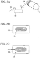
- reinforcing fibers 16 are impregnated with matrix plastic stored in a storage tank 18 so as to obtain fiber reinforced plastic 14.
- the fiber reinforced plastic 14 is wound onto the vessel body 2.
- a circumferentially oriented layer 10 is formed in which the fiber orientation direction of the fiber reinforced plastic layer 14 is the circumferential direction of the vessel body 2.
- an axially oriented layer 12 is formed.
- the fiber orientation direction of the fiber reinforced plastic layer 14 is set to the major-axis direction of the vessel body 2.
- the above-described method may be repeated in order to form additional layers on the axially oriented layer 12.
- the intermediate vessel 20 is heated in a furnace 22 so as to cure the fiber reinforced plastic layers.
- the heating temperature is preferably 40 to 180°C. In the case in which the heating temperature is lower than or higher than the aforementioned range, the fatigue properties and burst properties of the obtained pressure vessel 1 deteriorate.
- autofrettage treatment is conducted using an autofrettage treatment device 24 so that the compressive stress in the circumferential direction of the vessel surface after autofrettage is 95% of the vessel yield stress.
- the autofrettage treatment includes raising an internal pressure of the intermediate vessel 20 (the maximum value of the internal pressure of the vessel at this time is referred to as the autofrettage treatment pressure) so as to permanently deform the liner material (the vessel body 2), and then reducing the internal pressure of the vessel so as to impart compressive stress to the vessel body 2 by the rigidity of the fiber reinforced plastic layers 10 and 12.
- the evaluation techniques for the reinforcing fibers are as follows.
- Strand strength was divided by strand elastic modulus so as to calculate tensile elongation.
- the average cross-sectional area of a filament cross-section of a carbon fiber tow was calculated from the following Formula (1).
- the yield of the fiber tow is the mass per unit length of the carbon fiber tow (fineness), and was measured in conformity with JIS R7601.
- the density of the fiber tow was measured by the density gradient tube method in conformity with JIS R7601.
- a av 1 n ⁇ t p ⁇ 10 ⁇ 3
- the average diameter was calculated on the assumption that the cross-sectional form is completely round.
- the depth of the creases existing on filament surfaces of carbon fiber tow was defined as the difference in height between the highest portion and lowest portion in a region measuring 2 ⁇ m in the circumferential direction by 1 ⁇ m in the fiber axis direction.
- the difference in height was measured based on the measurement results for surface configuration obtained by scanning the probe on the surface of the filament using a scanning atomic force microscope (AFM). Specifically, the measurement was done as follows.
- the surface configuration was measured in a field measuring 2 to 2.5 ⁇ m in the circumferential direction of the filament surface and 1 ⁇ m in the fiber axis direction.
- the obtained measurement image was subjected to inverse transformation after removing the low-frequency components by two-dimensional Fourier transformation. From a planar image of the cross-section from which the curvature of the filament has been removed in this manner, the difference in height between the highest portion and the lowest portion was measured in the region measuring 2 ⁇ m in the circumferential direction by 1 ⁇ m in the fiber axis direction.
- the reinforcing fibers (i) to (viii) shown below were prepared.
- Reinforcing fibers (i): Filament diameter was approximately 5 ⁇ m, number of filaments was 24,000, strand strength was 5250 MPa, strand elastic modulus was 350 GPa, and elongation was 1.50%. The crease depth was 80 nm.
- Reinforcing fibers (iii) Carbon fibers MR35E-12K manufactured by Mitsubishi Rayon Co., Ltd. were used. These carbon fibers had a filament diameter of 7 ⁇ m, number of filaments of 12,000, strand strength of 4410 MPa, strand elastic modulus of 295 GPa, and elongation of 1.49%. The crease depth was 100 nm.
- Reinforcing fibers (iv): Carbon fibers HR40-12K manufactured by Mitsubishi Rayon Co., Ltd. were used. These carbon fibers had a filament diameter of 6 ⁇ m, number of filaments of 12,000, strand strength of 4610 MPa, strand elastic modulus of 390 GPa, and elongation of 1.18%. The crease depth was 20 nm.
- Reinforcing fibers (v) Carbon fibers MR60H-24K manufactured by Mitsubishi Rayon Co., Ltd. were used. These carbon fibers had a filament diameter of approximately 5 ⁇ m, number of filaments of 24,000, strand strength of 5800 MPa, strand elastic modulus of 290 GPa, and elongation of 2.00%. The crease depth was 80 nm.
- Reinforcing fibers (vi): Filament diameter was approximately 5 ⁇ m, number of filaments was 24,000, strand strength was 5220 MPa, strand elastic modulus was 360 GPa, and elongation was 1.45%. The crease depth was 80 nm.
- Reinforcing fibers (vii) These carbon fibers had a filament diameter of approximately 5 ⁇ m, number of filaments of 24,000, strand strength of 5250 MPa, strand elastic modulus of 320 GPa, and elongation of 1.64%. The crease depth was 80 nm.
- reinforcing fiber (i), reinforcing fibers (ii), reinforcing fibers (vi), reinforcing fibers (vii) and reinforcing fibers (viii) were manufactured as follows.
- Spinning solution was prepared by dissolving acrylonitrile polymer in dimethylacetoamide, and carbon-fiber-precursor fiber tows were obtained by subjecting this spinning solution to wet spinning in the manner shown below.
- the spinning solution was discharged into a first coagulation bath including a dimethylacetoamide aqueous solution with a concentration of 50 to 70 mass % and a temperature of 30 to 50°C; thereby, coagulated yarns were prepared.
- the coagulated yarns were subjected to drawing by a specified force in a second coagulation bath including a dimethylacetoamide aqueous solution with a concentration of 50 to 70 mass % and a temperature of 30 to 50°C, wet heat drawing was further conducted so that the length was 3.5 times or more longer than before the drawing. Thereby, the carbon-fiber-precursor fiber tows were obtained.
- the cross-sectional average diameter and the crease depth were adjusted by changing the concentration and the temperature of the coagulation bath and the drawing conditions. In order to maintain stability in the spinning process, a silicon oil solution was deposited.
- a plurality of carbon-fiber-precursor fiber tows arranged in parallel were put into a flameproofing furnace, and oxidizing gas such as air which was heated to 200 to 300°C, was blown to the carbon-fiber-precursor fiber tows under conditions of an extension rate of -2.0% or more (conditions by which fiber tows were contracted at a contraction rate of 2.0% or more). Thereby, the carbon-fiber-precursor fiber tows were flameproofed so as to obtain flameproofed fiber tows.
- oxidizing gas such as air which was heated to 200 to 300°C
- these flameproofed fiber tows were put into a carbonizing furnace, and were carbonized in an inert gas atmosphere at a temperature of 1300 to 2000°C under conditions of a high extension rate of -5.0% or more so as to obtain the carbon fiber tows.
- the carbonizing temperatures for manufacturing the reinforcing fiber (i), reinforcing fiber (ii), reinforcing fiber (vi), reinforcing fiber (vii) and reinforcing fiber (viii) were respectively 1800°C, 1550°C, 1950°C, 1600°C and 1550°C.
- Epoxy resin "#700B” manufactured by Mitsubishi Rayon Co., Ltd. Composition Ep828/XN1045/BYK-A506) was used.
- An aluminum vessel body having a capacity of 9 liters (total length: 540 mm, length of cylindrical section: 415 mm, outer diameter of cylindrical section: 163 mm, wall thickness at center of cylindrical section: 3 mm) was used.
- a pressure vessel having a normal filling pressure of 70 MPa was prepared by the following procedure.
- the reinforcing fibers (i) (elongation: 1.50%, elastic modulus: 350 GPa) were impregnated with matrix plastic so as to obtain the fiber reinforced plastic 14.
- the fiber reinforced plastic 14 was wound onto the vessel body 2, and fiber reinforced plastic layers of 5-layer structure were formed.
- the fiber reinforced plastic layers had a five-layer structure of circumferentially oriented layer (C) / axially oriented layer (H) / circumferentially oriented layer (C) / axially oriented layer (H) / circumferentially oriented layer (C) in the order in which they were arranged from the inside (vessel body side) toward the outside (outer side).
- the intermediate vessel 20 was put into a heating furnace 22, and the internal furnace temperature was raised from room temperature to 135°C at 1°C/minute.
- the internal furnace temperature was reduced to 60°C at 1°C/minute, and then the intermediate vessel 20 was removed from the heating furnace 22, and the intermediate vessel 20 was cooled to room temperature.
- the mass of the fiber reinforced plastic layers was 5,612 g.
- the intermediate vessel 20 was subjected to autofrettage treatment at an autofrettage treatment pressure of 158 MPa using an autofrettage treatment device 24; thereby, compressive stress was applied to the vessel body 2 so as to obtain the pressure vessel 1.
- the pressure vessel was set in a hydraulic burst tester (manufactured by Mitsubishi Rayon Co., Ltd.), hydraulic pressure was applied to the pressure vessel at a pressure boosting rate of 1.4 MPa/sec or less, and pressure was measured at the time when the pressure vessel broke.
- burst pressure breakage pressure
- burst pressure breakage pressure
- the pressure vessel was set in a hydraulic cycle tester (manufactured by Mitsubishi Rayon Co., Ltd.). The internal pressure of the pressure vessel was raised from atmospheric pressure to a pressure that was 5/3 times as high as the normal filling pressure, and then the internal pressure was reduced to atmospheric pressure. Such pressure fluctuation operations was repeated at a frequency of approximately twice per minute until the pressure vessel was burst, and the number of cycles of the pressure fluctuation operations until bursting was measured.
- the standards prescribe that the number of cycles until bursting in the fatigue properties testing be 11,250 or more, and considering safety, the number of cycles until bursting in the fatigue properties was required to be 12,500 or more.
- the mass of the fiber reinforced plastic layers of each pressure vessel was measured.
- the burst pressure (BP) of the obtained pressure vessel 1 was 211 MPa. This value was equivalent to that of approximately 3 times as high as the normal filling pressure (FP).
- the bursting state at that time in each case was an ideal bursting mode in which only a hole was opened at or in the vicinity of the center of the cylindrical section without splitting of the pressure vessel.
- the number of cycles of the pressure fluctuation operations until bursting for the pressure vessel 1 was 16,190.
- the burst position at that time was observed in a liner portion in the cylindrical section of the pressure vessel.
- the pressure vessel 1 of the first embodiment exhibited excellent results in burst properties and fatigue properties, which showed that the pressure vessel had the potential for further weight reduction.
- a pressure vessel having a normal filling pressure (FP) of 70 MPa was prepared by the following procedure.
- fiber reinforced plastic layers having the fiber reinforced plastic 14 in which the reinforcing fibers (ii) (elongation: 1.64%, elastic modulus: 320 GPa) were impregnated with matrix plastic, were formed on the vessel body 2 so as to obtain the intermediate vessel 20.
- the fiber reinforced plastic layers had the same 5-layer structure as that of the first embodiment.
- measurement result of the thickness of the fiber reinforced plastic layers at the center of the cylindrical section was approximately 13 mm.
- the intermediate vessel 20 was subjected to heat treatment in the same way as that in the first embodiment.
- the mass of the fiber reinforced plastic layers was 5,633 g.
- the intermediate vessel 20 was subjected to autofrettage treatment in the same way as that in the first embodiment so as to obtain the pressure vessel.
- the autofrettage treatment pressure was 140 MPa.
- the burst pressure (BP) of the pressure vessel was 198 MPa. This value was equivalent to that of approximately 2.8 times as high as the normal filling pressure (FP).
- the bursting state at that time in each case was an ideal bursting mode in which only a hole was opened at or in the vicinity of the center of the cylindrical section without splitting of the pressure vessel.
- This pressure vessel was an example in which reinforcing fibers having a low elastic modulus and ideal elongation was used. Compared with the properties of pressure vessels of this class that were generally known, and even compared with the standards to which the safety factor was applied, adequate performance was exhibited in terms of burst properties and fatigue properties. There also remained scope, albeit slight, for weight reduction.
- a pressure vessel having a normal filling pressure (FP) of 70 MPa was prepared by the following procedure.
- fiber reinforced plastic layers having the fiber reinforced plastic 14 in which the reinforcing fibers (vi) (elongation: 1.45%, strand elastic modulus: 360 GPa) were impregnated with matrix plastic, were formed on the vessel body 2 so as to obtain the intermediate vessel 20.
- the fiber reinforced plastic layers had the same 5-layer structure as that of the first embodiment.
- measurement result of the thickness of the fiber reinforced plastic layers at the center of the cylindrical section was approximately 13 mm.
- the intermediate vessel 20 was subjected to heat treatment in the same way as that in the first embodiment.
- the mass of the fiber reinforced plastic layers was 5,580 g.
- the intermediate vessel 20 was subjected to autofrettage treatment in the same way as that in the first embodiment so as to obtain the pressure vessel.
- the autofrettage treatment pressure was 140 MPa.
- the burst pressure (BP) of the obtained pressure vessel 1 was 208 MPa. This value was equivalent to that of approximately 3 times as high as the normal filling pressure (FP).
- the bursting state at that time in each case was an ideal bursting mode in which only a hole was opened at or in the vicinity of the center of the cylindrical section without splitting of the pressure vessel.
- the number of cycles of the pressure fluctuation operations until bursting for the pressure vessel 1 was 18,310.
- the burst position at that time was observed in the liner portion of the cylindrical section of the pressure vessel.
- This pressure vessel 1 of the third embodiment exhibited excellent results in burst properties and fatigue properties, which showed that the pressure vessel had the potential for further weight reduction.
- a pressure vessel having a normal filling pressure (FP) of 70 MPa was prepared by the following procedure.
- fiber reinforced plastic layers having the fiber reinforced plastic 14 in which the reinforcing fibers (vii) (elongation: 1.64%, elastic modulus: 320 GPa) were impregnated with matrix plastic, were formed on the vessel body 2 so as to obtain the intermediate vessel 20.
- the fiber reinforced plastic layers had the same 5-layer structure as that of the first embodiment.
- measurement result of the thickness of the fiber reinforced plastic layers at the center of the cylindrical section was approximately 13 mm.
- the intermediate vessel 20 was subjected to heat treatment in the same way as that in the first embodiment.
- the mass of the fiber reinforced plastic layers was 5,633 g.
- the intermediate vessel 20 was subjected to autofrettage treatment in the same way as that in the first embodiment so as to obtain the pressure vessel.
- the autofrettage treatment pressure was 140 MPa.
- the burst pressure (BP) of the pressure vessel was 206 MPa. This value was equivalent to that of approximately 2.9 times as high as the normal filling pressure (FP).
- the bursting state at that time in each case was an ideal bursting mode in which only a hole was opened at or in the vicinity of the center of the cylindrical section without splitting of the pressure vessel.
- This pressure vessel was an example in which reinforcing fiber having a low elastic modulus and ideal elongation was used. Compared with the properties of pressure vessels of this class that were generally known, and even compared with the standards to which the safety factor was applied, adequate performance was exhibited in terms of burst properties and fatigue properties. There also remained scope, albeit slight, for weight reduction.
- a pressure vessel having a normal filling pressure of 70 MPa was prepared by the following procedure.
- fiber reinforced plastic layers having the fiber reinforced plastic 14 in which the reinforcing fibers (viii) (elongation: 1.70%, elastic modulus: 310 GPa) were impregnated with matrix plastic, were formed on the vessel body 2 so as to obtain the intermediate vessel 20.
- the fiber reinforced plastic layers had the same 5-layer structure as that of the first embodiment.
- measurement result of the thickness of the fiber reinforced plastic layers at the center of the cylindrical section was approximately 13 mm.
- the intermediate vessel 20 was subjected to heat treatment in the same way as that in the first embodiment.
- the mass of the fiber reinforced plastic layers was 5,640 g.
- the intermediate vessel 20 was subjected to autofrettage treatment in the same way as that in the first embodiment so as to obtain the pressure vessel.
- the autofrettage treatment pressure was 140 MPa.
- the burst pressure (BP) of the pressure vessel was 207 MPa. This value was equivalent to that of approximately 3 times as high as the normal filling pressure.
- the bursting state at that time in each case was an ideal bursting mode in which only a hole was opened at or in the vicinity of the center of the cylindrical section without splitting of the pressure vessel.
- the number of cycles of the pressure fluctuation operations until bursting for the pressure vessel was 12,600.
- the burst position at that time was observed in the liner portion of the cylindrical section of the pressure vessel.
- This pressure vessel was an example in which reinforcing fiber having a low elastic modulus and ideal elongation was used. Compared with the properties of pressure vessels of this class that were generally known, and even compared with the standards to which the safety factor was applied, adequate performance was exhibited in terms of burst properties and fatigue properties.
- a pressure vessel having a normal filling pressure (FP) of 70 MPa was prepared by the following procedure.
- reinforcing fibers were used which had ideal elongation; however, of which elastic modulus was somewhat low for a pressure vessel.
- fiber reinforced plastic layers having the fiber reinforced plastic 14 in which the reinforcing fibers (iii) (elongation: 1.5%, elastic modulus: 295 GPa) were impregnated with matrix plastic were formed on the vessel body 2 so as to obtain the intermediate vessel 20.
- the fiber reinforced plastic layers had the same 5-layer structure as that of the first embodiment.
- measurement result of the thickness of the fiber reinforced plastic layers at the center of the cylindrical section was approximately 13 mm.
- the intermediate vessel 20 was subjected to heat treatment in the same way as that in the first embodiment.
- the mass of the fiber reinforced plastic layers was 5,648 g.
- the intermediate vessel 20 was subjected to autofrettage treatment in the same way as that in the first embodiment so as to obtain the pressure vessel.
- the autofrettage treatment pressure was 130 MPa.
- the burst pressure (BP) of the pressure vessel was 179 MPa. This value was equivalent to that of 2.56 times as high as the filling pressure.
- the bursting state at that time in each case was an ideal bursting mode in which only a hole was opened at or in the vicinity of the center of the cylindrical section without splitting of the pressure vessel.
- This pressure vessel was an example in which reinforcing fiber having a low elastic modulus and ideal elongation was used. Compared with the properties of pressure vessels of this class that were generally known, it was able to satisfy the standards; however, compared with the standards to which the safety factor was applied, it was undeniable that there was a slight deficiency in fatigue properties.
- a pressure vessel having a normal filling pressure (FP) of 70 MPa was prepared by the following procedure.
- fiber reinforced plastic layers having the fiber reinforced plastic 14 in which the reinforcing fibers (iv) (elongation: 1.20%, elastic modulus: 390 GPa) were impregnated with matrix plastic were formed on the vessel body 2 so as to obtain the intermediate vessel 20.
- the fiber reinforced plastic layers had the same 5-layer structure as that of the first embodiment.
- measurement result of the thickness of the fiber reinforced plastic layers at the center of the cylindrical section was approximately 13 mm.
- the intermediate vessel 20 was subjected to heat treatment in the same way as that in the first embodiment.
- the mass of the fiber reinforced plastic layers was 5,640 g.
- the intermediate vessel 20 was subjected to autofrettage treatment in the same way as that in the first embodiment so as to obtain the pressure vessel.
- the autofrettage treatment pressure was 125 MPa.
- the burst pressure (BP) of the pressure vessel was 181 MPa. This value was equivalent to that of approximately 2.6 times as high as the filling pressure. With regard to the bursting state at that time, the burst portion was observed at the center of the cylindrical section.
- the bursting mode was such that, in the liner itself, only a hole was opened at or in the vicinity of the center of the cylindrical section; however, the fiber reinforced plastic layers on the outer side broke into two pieces or more.
- the number of cycles of the pressure fluctuation operations until bursting for the pressure vessel was 19,821.
- the burst position at that time was observed in the liner portion of the cylindrical section of the pressure vessel.
- This pressure vessel was an example in which reinforcing fibers having a high elastic modulus was used.
- the standard values for vessel properties as well as the burst properties and fatigue properties required when considering safety may be said to have been satisfied.
- the difference between autofrettage treatment pressure and burst pressure was small. Therefore, there was a possibility of bursting during autofrettage treatment due to variations in the strength of the reinforcing fibers. For this reason, the balancing of the strength and the elastic modulus of the reinforcing fiber was inadequate.
- a pressure vessel having a normal filling pressure (FP) of 70 MPa was prepared by the following procedure.
- fiber reinforced plastic layers having the fiber reinforced plastic 14 in which the reinforcing fibers (v) (elongation: 2.0%, elastic modulus: 290 GPa) were impregnated with matrix plastic were formed on the vessel body 2 so as to obtain the intermediate vessel 20.
- the fiber reinforced plastic layers had the same 5-layer structure as that of the first embodiment.
- measurement result of the thickness of the fiber reinforced plastic layers at the center of the cylindrical section was approximately 13 mm.
- the intermediate vessel 20 was subjected to heat treatment in the same way as that in the first embodiment.
- the mass of the fiber reinforced plastic layers was 5,652 g.
- the intermediate vessel 20 was subjected to autofrettage treatment in the same way as that in the first embodiment so as to obtain the pressure vessel.
- the autofrettage treatment pressure was 125 MPa.
- the burst pressure (BP) of the pressure vessel was 228 MPa. This value was equivalent to that of approximately 3.3 times as high as the normal filling pressure.
- the bursting state at that time in each case was an ideal bursting mode in which only a hole was opened at or in the vicinity of the center of the cylindrical section without splitting of the pressure vessel.
- This pressure vessel was an example in which reinforcing fiber having comparatively high strength was used. Compared with the properties of general pressure vessels having this normal filling pressure, the standard values for vessel properties were fully satisfied with regard to burst properties; however, fatigue properties were insufficient for the standard values. Accordingly, the balancing of the strength and the elastic modulus of the reinforcing fibers was inadequate.
- Table 2 shows the results of the above embodiments and comparative embodiments.
- the pressure vessels of the first and second embodiments had excellent balancing of burst properties and fatigue properties, and the potential for further weight reduction due to a high elastic modulus was confirmed.
- the pressure vessel of the present invention is suitable for the fuel tanks of various transport vehicles such as automobiles.
Landscapes
- Engineering & Computer Science (AREA)
- Mechanical Engineering (AREA)
- General Engineering & Computer Science (AREA)
- Filling Or Discharging Of Gas Storage Vessels (AREA)
Description
- The present invention relates to a pressure vessel used as a storage vessel for high-pressure gas and the like, and to carbon fibers used therein.
- This application claims priority from Japanese Patent Application No.
2003-305228 filed August 28, 2003 - Conventionally, containers made of steel are generally used as storage vessels for high-pressure gas.
- However, steel storage vessels are heavy in weight, and much labor for movement, transport and the like is required.
- For example, for automobiles using gaseous fuel, lighter-weight fuel storage vessels are required for the purpose of reducing vehicle weight in order to keep the fuel consumption amount low.
- As storage vessels for high-pressure gas, instead of the conventional steel storage vessels, pressure vessels made of composite material in which liner material (vessel body) of plastic or metal is strengthened by reinforcing fibers, have come into use. High filling pressure and reduction in weight are realized by pressure vessels having this fiber-reinforced composite material.
- In the process for manufacturing the pressure vessels having the fiber-reinforced composite material, there exists the filament winding method (hereinafter, referred to as "FW method") as a representative method for winding the reinforcing fibers.
- This method is a method for manufacturing a pressure vessel having fiber-reinforced composite material, which includes winding continuous reinforcing fibers impregnated with plastic onto liner material (a vessel body), and then curing the plastic.
- Pressure vessels can be easily manufactured by adopting this FW method. However, in the case in which pressure vessels having, for example, a burst pressure (breakage pressure) of more than 65 MPa are manufactured, the rate of occurrence of the strength of the reinforcing fibers tends to decline. Consequently, it is necessary to thickly wind the reinforcing fibers as a countermeasure thereto, resulting in a problem of increased vessel weight.
- Japanese Unexamined Patent Application, First Publication No.
H8-285189 H9-280496 - Adequate burst pressure is obtained with the aforementioned conventional pressure vessels; however, other problems are engendered as described below.
- With regard to the properties required for pressure vessels, not only burst properties are important, but also fatigue properties are important.
- Particularly in the case of pressure vessels in which liner material (a vessel body) having metal such as aluminum is used, it is possible to impart compressive stress to the liner material by conducting autofrettage treatment at high pressure. It is possible to improve fatigue properties by conducting the autofrettage treatment so that this compressive stress is within the range of linear characteristics of the liner material. However, in the case in which the pressure vessel is designed with the emphasis on the compressive stress imparted to the liner material, burst pressure is lowered to less than needs. On the other hand, in the case in which the pressure vessel is designed with the emphasis on the burst pressure, the required compressive stress is not imparted. As a result, there is a problem that the used amount of the reinforcing fibers must be increased in order to realize a suitable pressure vessel, resulting in increasing the weight of the vessel and so on.
-
JP 2000 249294 A -
US 5 385 263 A relates to a compressed gas mobile storage module and lightweight composite cylinders. The cylinders may have a core cylinder wrapped with three layers of wound fiber. The inner and outer layers are axially-wound glass fiber and the intermediate layer is hoop-wound carbon fiber. The elastic modulus of the carbon fiber is approximately 30 x 106 psi to 50 x 106 psi. -
JP 2003 222299 A - The present invention aims to provide a pressure vessel which is superior in both of fatigue properties and burst properties, and that is also lightweight, and to provide reinforcing fibers used in the pressure vessel. The present invention is a carbon reinforcing fiber for a pressure vessel of which a strand elastic modulus is 305 GPa or higher, and a tensile elongation is 1.45 to 1.70% that includes a plurality of filaments bearing creases on the surface thereof, and difference in height between the highest portion and the lowest portion of the creases may be 40 nm or more.
- The strand elastic modulus may be 305 GPa to 420 GPa.
- The carbon reinforcing fiber for a pressure vessel may include a plurality of filaments having an average diameter of 6 pm or less. The present invention is also a pressure vessel including a vessel body and a fiber reinforced plastic layer formed on the surface of the vessel body, wherein the fiber reinforced plastic layer includes fiber reinforced plastic in which reinforcing fibers are impregnated with plastic. The reinforcing fibers are carbon reinforcing fibers and a strand elastic modulus of the carbon reinforcing fibers is 305 GPa or higher, and a tensile elongation of the carbon reinforcing fibers is 1.45 to 1.70%, which comprises a plurality of filaments bearing creases on the surface thereof, and difference in height between the highest portion and the lowest portion of said creases is 40 nm or more. According to the aforementioned aspect, a pressure vessel can be realized which is superior in both of fatigue properties and burst properties without being superior in only one vessel property, and which is lightweight.
- The strand elastic modulus of the reinforcing fiber may be 305 GPa to 420 GPa. The vessel body may be made of metal.
- Filling pressure may be 30 MPa or higher.
- According to the aforementioned aspect, it is possible to provide a pressure vessel which is superior in both of fatigue properties and burst properties and which is lightweight, by forming a fiber reinforced plastic layer which includes these fibers impregnated with plastic on the surface of a vessel body.
-
-
FIG. 1 is a partial sectional view showing an example of one embodiment of the pressure vessel of the present invention. -
FIG. 2A is a typical view showing the process of forming fiber reinforced plastic layers in the method for manufacturing a pressure vessel. -
FIG. 2B is a typical view showing the process of curing the plastic in the method for manufacturing a pressure vessel. -
FIG. 2C is a typical view showing the process of autofrettage treatment in the method for manufacturing a pressure vessel. - Suitable embodiments of the present invention are described below with reference to drawings. However, the present embodiment is not limited to the various embodiments that follow, and, for example, the fellow constituent elements of these embodiments may be appropriately combined.
- The pressure vessel of the present invention includes a vessel body and a fiber reinforced plastic layer formed on the surface of this vessel body. The fiber reinforced plastic layer includes fiber reinforced plastic in which reinforcing fibers are impregnated with plastic, and specified reinforcing fibers are used as these reinforcing fibers. The specified reinforcing fiber is a fiber of which a strand elastic modulus is 305 GPa or higher and of which a tensile elongation is 1.45 to 1.70%.
- In the case in which the strand elastic modulus of the reinforcing fiber is less than 305 GPa, it is necessary to increase the winding amount of the reinforcing fibers in order to obtain sufficient rigidity, which results in a vessel of which wall thickness is thick. As a results, vessel weight is increased.
- In the case in which the tensile elongation of the reinforcing fiber is less than 1.45%, the winding amount of the reinforcing fiber must be increased, because the reinforcing fiber lacks sufficient strength. This inevitably leads to thickened walls, resulting in a vessel which has excessive fatigue properties and is heavy in weight. On the other hand, in the case in which the tensile elongation of the reinforcing fiber is more than 1.70%, the strength of the reinforcing fiber is sufficient; however, the reinforcing fiber does not have sufficient elastic modulus commensurate with this strength. Accordingly, in the fiber reinforced plastic layer, rigidity is excessively high compared with the other properties, resulting in a vessel that has excessive burst properties.
- The upper limit of the strand elastic modulus of the reinforcing fiber is preferably 420 GPa or less. When using reinforcing fiber of which the strand elastic modulus is more than 420 GPa, sufficient rigidity is obtained even if the amount of composite material wound onto the vessel body is reduced. Therefore, a lightweight pressure vessel can be obtained. However, there is the problem that the obtained pressure vessel having thin wall thickness, is inferior in shock performance and fire exposure performance. Furthermore, surface adhesiveness with the plastic (matrix plastic) with which the reinforcing fibers are impregnated, is insufficient; thereby, the performance (pressure resistance) of the pressure vessel declines.
- Balancing these properties and performances of the reinforcing fiber is particularly important for high-pressure vessels using metal liners and for high-pressure vessels of which filling pressure is 30 MPa or higher. This is because, in high-pressure vessels in which metal liners are used and of which filling pressure is 30 MPa or higher, balancing of the fatigue properties and the burst properties tends to deteriorate, that is, excessive performance by one or the other tends to occur; as a results, the thickness of the fiber reinforced plastic layer must be increased in order to satisfy the other set of properties, and the weight of the pressure vessel increases.
- Accordingly, in consideration of the balancing of the elastic modulus and the strength of the reinforcing fiber, reinforcing fibers having sufficient strength and elastic modulus commensurate with that strength, are used in the present invention. By forming a fiber reinforced plastic layer having this type of reinforcing fibers on the vessel body, it is possible to offer a pressure vessel with little waste, in which the properties and performances of the pressure vessel such as burst properties and fatigue properties are well balanced and satisfactory, the used amount of the reinforcing fibers is minimized, and weight increase due to the conventional formation of thick walls, is inhibited.
- This type of reinforcing fiber for pressure vessels is a fiber having a strand elastic modulus of 305 GPa or higher and a tensile elongation of 1.45% to 1.70%, and examples thereof may include carbon fibers, boron fibers and the like, having these properties. Among these, carbon fibers are very suitable. The strand elastic modulus is preferably 310 GPa or higher, and is more preferably 320 GPa or higher. The tensile elongation is preferably 1.50% to 1.70%, and is more preferably 1.55% to 1.70%.
- Furthermore, carbon fibers having a strand elastic modulus of 420 GPa or less, are more preferable. In particular, for manufacturing the carbon fibers having a strand elastic modulus of more than 420 GPa, a carbonizing temperature of more than 2000°C is required. As a result, a compressive strength, a shear strength and the like tend to decrease, and anisotropy of the composite material increases; thereby, the mechanical properties of the pressure vessel tend to decline. Furthermore, since the carbon fibers are hard to handle, problems tend to occur in which workability in the process of filament winding or the like deteriorates.
- The upper limit of the strand elastic modulus is preferably 400 GPa, and is more preferably 380 GPa.
- Furthermore, filaments included in the carbon fiber are preferably filaments of which an average diameter is 6 µm or less. As the average diameter of the precursor fiber decreases, the elastic modulus is more readily manifested. As a result, when manufacturing carbon fiber tows having a predetermined elastic modulus, it is possible to apply a lower carbonizing temperature. In the case in which the carbonizing temperature is low, it is possible to manufacture carbon fiber tows which realize high strand strength, which further exhibit high shear strength and high compressive strength, and which have excellent mechanical properties. Accordingly, carbon fibers having a small fiber diameter are more preferable, particularly an average diameter of the carbon fibers is preferably 6 µm or less, and is more preferably 5.5 µm or less. There are no particular limits on the lower limit of diameter; however, since spinnability of the precursor fibers deteriorates as the fiber diameter decreases, 3 µm or more is preferable.
- Ordinarily, 1,000 to 50,000 filaments having an average diameter of 5 to 8 µm are brought together to constitute a carbon fiber.
- Each filament included in the carbon fiber preferably bears a plurality of creases on the surface thereof, which have difference in height between the highest portion and the lowest portion thereof is 40 nm or more. By means of these surface creases, the wettability of the carbon fiber and the matrix plastic is improved, and the adhesion of the surface becomes firmer. As a result, it is possible to stably obtain pressure vessels having excellent mechanical properties, and to manufacture pressure vessels with stable quality.
- Furthermore, the difference in height between the highest portion and the lowest portion of the creases is more preferably 10% or less of the diameter of the filament.
- The depth of the creases existing on the surfaces of the filaments of the carbon fiber is defined as the difference in height between the highest portion and the lowest portion in a region measuring 2 µm in the circumferential direction by 1 µm in the fiber axis direction. The creases on the surface of the filament are in a shape of peak-valley form having a length of 1 µm or more in a certain direction. There are no particular restrictions on the direction, and it may be parallel or perpendicular to the fiber axis direction, or be angled relative to the fiber axis direction. On a surface of an ordinary carbon fiber obtained by the common method for manufacturing carbon fiber tows, the creases are approximately parallel to the fiber axis direction.
- The height differences in the creases may be measured as follows, based on the results of observation of the surface configuration of the filament measured using a scanning atomic force microscope (AFM).
- Several filaments of a carbon fiber tow are placed on a specimen stand, both ends thereof are fixed, and Dotite is coated around them so as to prepare measurement samples. As the AFM, an atomic force microscope (manufactured by Seiko Instruments KK, SPI3700/SPA-300 (brand name)) is used which is provided with a cantilever made of silicon nitride and having a probe formed at the tip. The probe is scanned in a scanning length of 1 µm in the fiber axis direction of the filament in the AFM mode, and this scanning of the probe is repeatedly conducted over a scanning field measuring 2 to 2.5 µm in the circumferential direction of the filament while shifting the probe in the circumferential direction little by little. By this means, the surface configuration is measured in a field measuring 2 to 2.5 µm in the circumferential direction of the filament surface and 1 µm in the fiber axis direction. The obtained measurement image is subjected to inverse transformation after removing the low-frequency components by two-dimensional Fourier transformation. From a planar image of the cross-section from which the curvature of the filament has been removed in this manner, the difference in height between the highest portion and the lowest portion is measured in the region measuring 2 µm in the circumferential direction by 1 µm in the fiber axis direction.
-
FIG. 1 is a partial sectional view showing an example of one embodiment of the pressure vessel of the present invention. - In the
pressure vessel 1 shown inFIG. 1 , fiber reinforced plastic layers 10 and 12 having the aforementioned fiber reinforced plastic are provided on an approximatelycylindrical vessel body 2. In this example, the fiber reinforcedplastic layers aperture 4 of thevessel body 2, that is, a cylindrical section 3 and abottom portion 5. - There are no particular restrictions on the
vessel body 2 as long as it is formed from material that prevents leakage of the gas filled therein; however, avessel body 2 formed from plastic or metal is preferable. Examples of plastic include high-density polyethylene. Examples of metal include aluminum alloy, magnesium alloy, iron and the like. In particular, aluminum alloy is well suited to weight saving for thevessel body 2. - With regard to the fiber reinforced plastic layers, a single layer is acceptable; however, a multi-layer structure as in this embodiment is preferable.
- In this embodiment, a two-layer configuration is adopted in which the fiber reinforced plastic layer (axially oriented layer) 12 formed by winding fiber reinforced plastic so that the orientation direction of the fibers is the major-axis direction of the
vessel body 2 is on the fiber reinforced plastic layer (circumferentially oriented layer) 10 formed by winding fiber reinforced plastic so that the orientation direction of the fibers is the circumferential direction of thevessel body 2. - In the present invention, the fiber reinforced plastic layers are not limited to the illustrated configuration, and a multi-layer structure of three layers or more that alternately laminates a circumferentially oriented layer and an axially oriented layer on the vessel body, may be adopted.
- In particular, it is preferable that the outermost layer of the fiber reinforced plastic layers be the circumferentially oriented layer; thereby, a satisfactory external appearance is obtained. The number of layers and their thicknesses may be set regarding applications of the vessel, type of contents, size, and the like.
- As to the plastic (matrix plastic) with which the reinforcing fibers are impregnated, there are no particular restrictions as long as it may be generally used for fiber reinforced plastic layers. Examples of the plastic includes epoxy resin, vinyl ester resin, phenol resin, acrylic resin and the like.
- One example of the method for manufacturing the
aforementioned pressure vessel 1 is described below. - As shown in
FIG. 2A , reinforcingfibers 16 are impregnated with matrix plastic stored in astorage tank 18 so as to obtain fiber reinforcedplastic 14. - Subsequently, while rotating the
vessel body 2 in the circumferential direction, the fiber reinforcedplastic 14 is wound onto thevessel body 2. By this means, a circumferentially orientedlayer 10 is formed in which the fiber orientation direction of the fiber reinforcedplastic layer 14 is the circumferential direction of thevessel body 2. - Next, an axially oriented
layer 12 is formed. When forming the axially orientedlayer 12, the fiber orientation direction of the fiber reinforcedplastic layer 14 is set to the major-axis direction of thevessel body 2. By this means, anintermediate vessel 20 having fiber reinforced plastic layers of multi-layer structure in which the circumferentially orientedlayer 10 and the axially orientedlayer 12 is alternately laminated, is obtained. - Here, the above-described method may be repeated in order to form additional layers on the axially oriented
layer 12. - Next, as shown in
FIG. 2B , theintermediate vessel 20 is heated in afurnace 22 so as to cure the fiber reinforced plastic layers. - The heating temperature is preferably 40 to 180°C. In the case in which the heating temperature is lower than or higher than the aforementioned range, the fatigue properties and burst properties of the obtained
pressure vessel 1 deteriorate. - Subsequently, as shown in
FIG. 2C , autofrettage treatment is conducted using anautofrettage treatment device 24 so that the compressive stress in the circumferential direction of the vessel surface after autofrettage is 95% of the vessel yield stress. Here, the autofrettage treatment includes raising an internal pressure of the intermediate vessel 20 (the maximum value of the internal pressure of the vessel at this time is referred to as the autofrettage treatment pressure) so as to permanently deform the liner material (the vessel body 2), and then reducing the internal pressure of the vessel so as to impart compressive stress to thevessel body 2 by the rigidity of the fiber reinforcedplastic layers - In this manner, the pressure vessel is manufactured.
- The pressure vessel of the present invention is described below by means of specific embodiments.
- The evaluation techniques for the reinforcing fibers are as follows.
- These were evaluated in conformity with JIS R7601.
- Strand strength was divided by strand elastic modulus so as to calculate tensile elongation.
- First, using the yield, density and number of filaments (filament quantity) of the fiber tow, the average cross-sectional area of a filament cross-section of a carbon fiber tow was calculated from the following Formula (1).
- The yield of the fiber tow is the mass per unit length of the carbon fiber tow (fineness), and was measured in conformity with JIS R7601.
- The density of the fiber tow was measured by the density gradient tube method in conformity with JIS R7601.

- Aav: average cross-sectional area of filament
- n: number of filaments composing tow
- t: yield (Tex)
- ρ: density (g/cm3)
- From the obtained average cross-sectional area of the filament, the average diameter was calculated on the assumption that the cross-sectional form is completely round.
- The depth of the creases existing on filament surfaces of carbon fiber tow was defined as the difference in height between the highest portion and lowest portion in a region measuring 2 µm in the circumferential direction by 1 µm in the fiber axis direction. The difference in height was measured based on the measurement results for surface configuration obtained by scanning the probe on the surface of the filament using a scanning atomic force microscope (AFM). Specifically, the measurement was done as follows.
- Several filaments of a carbon fiber tow were placed on a specimen stand, both ends thereof were fixed, and Dotite was applied around them so as to prepare measurement samples. As the AFM, an atomic force microscope (manufactured by Seiko Instruments KK, SPI3700/SPA-300 (brand name)) was used which was provided with a cantilever made of silicon nitride and having a probe formed at the tip. The probe was scanned in a scanning length of 1 µm in the fiber axis direction of the filament in the AFM mode, and this scanning of the probe was repeatedly conducted over a scanning field measuring 2 to 2.5 µm in the circumferential direction of the filament while shifting the probe in the circumferential direction little by little. By this means, the surface configuration was measured in a field measuring 2 to 2.5 µm in the circumferential direction of the filament surface and 1 µm in the fiber axis direction. The obtained measurement image was subjected to inverse transformation after removing the low-frequency components by two-dimensional Fourier transformation. From a planar image of the cross-section from which the curvature of the filament has been removed in this manner, the difference in height between the highest portion and the lowest portion was measured in the region measuring 2 µm in the circumferential direction by 1 µm in the fiber axis direction.
- The reinforcing fibers (i) to (viii) shown below were prepared.
- Reinforcing fibers (i): Filament diameter was approximately 5 µm, number of filaments was 24,000, strand strength was 5250 MPa, strand elastic modulus was 350 GPa, and elongation was 1.50%. The crease depth was 80 nm.
- Reinforcing fibers (ii): Filament diameter was approximately 5 µm, number of filaments was 24,000, strand strength was 4960 MPa, strand elastic modulus was 320 GPa, and elongation was 1.55%. The crease depth was 80 nm.
- Reinforcing fibers (iii): Carbon fibers MR35E-12K manufactured by Mitsubishi Rayon Co., Ltd. were used. These carbon fibers had a filament diameter of 7 µm, number of filaments of 12,000, strand strength of 4410 MPa, strand elastic modulus of 295 GPa, and elongation of 1.49%. The crease depth was 100 nm.
- Reinforcing fibers (iv): Carbon fibers HR40-12K manufactured by Mitsubishi Rayon Co., Ltd. were used. These carbon fibers had a filament diameter of 6 µm, number of filaments of 12,000, strand strength of 4610 MPa, strand elastic modulus of 390 GPa, and elongation of 1.18%. The crease depth was 20 nm.
- Reinforcing fibers (v): Carbon fibers MR60H-24K manufactured by Mitsubishi Rayon Co., Ltd. were used. These carbon fibers had a filament diameter of approximately 5 µm, number of filaments of 24,000, strand strength of 5800 MPa, strand elastic modulus of 290 GPa, and elongation of 2.00%. The crease depth was 80 nm.
- Reinforcing fibers (vi): Filament diameter was approximately 5 µm, number of filaments was 24,000, strand strength was 5220 MPa, strand elastic modulus was 360 GPa, and elongation was 1.45%. The crease depth was 80 nm.
- Reinforcing fibers (vii): These carbon fibers had a filament diameter of approximately 5 µm, number of filaments of 24,000, strand strength of 5250 MPa, strand elastic modulus of 320 GPa, and elongation of 1.64%. The crease depth was 80 nm.
- Reinforcing fiber (viii): Filament diameter was approximately 5 µm, number of filaments was 24,000, strand strength was 5270 MPa, strand elastic modulus was 310 GPa, and elongation was 1.70%. The crease depth was 80 nm.
- Now, reinforcing fiber (i), reinforcing fibers (ii), reinforcing fibers (vi), reinforcing fibers (vii) and reinforcing fibers (viii) were manufactured as follows.
- Spinning solution was prepared by dissolving acrylonitrile polymer in dimethylacetoamide, and carbon-fiber-precursor fiber tows were obtained by subjecting this spinning solution to wet spinning in the manner shown below. First, the spinning solution was discharged into a first coagulation bath including a dimethylacetoamide aqueous solution with a concentration of 50 to 70 mass % and a temperature of 30 to 50°C; thereby, coagulated yarns were prepared. Next, the coagulated yarns were subjected to drawing by a specified force in a second coagulation bath including a dimethylacetoamide aqueous solution with a concentration of 50 to 70 mass % and a temperature of 30 to 50°C, wet heat drawing was further conducted so that the length was 3.5 times or more longer than before the drawing. Thereby, the carbon-fiber-precursor fiber tows were obtained.
- The cross-sectional average diameter and the crease depth were adjusted by changing the concentration and the temperature of the coagulation bath and the drawing conditions. In order to maintain stability in the spinning process, a silicon oil solution was deposited.
- Next, a plurality of carbon-fiber-precursor fiber tows arranged in parallel were put into a flameproofing furnace, and oxidizing gas such as air which was heated to 200 to 300°C, was blown to the carbon-fiber-precursor fiber tows under conditions of an extension rate of -2.0% or more (conditions by which fiber tows were contracted at a contraction rate of 2.0% or more). Thereby, the carbon-fiber-precursor fiber tows were flameproofed so as to obtain flameproofed fiber tows. Next, these flameproofed fiber tows were put into a carbonizing furnace, and were carbonized in an inert gas atmosphere at a temperature of 1300 to 2000°C under conditions of a high extension rate of -5.0% or more so as to obtain the carbon fiber tows. Here, the carbonizing temperatures for manufacturing the reinforcing fiber (i), reinforcing fiber (ii), reinforcing fiber (vi), reinforcing fiber (vii) and reinforcing fiber (viii) were respectively 1800°C, 1550°C, 1950°C, 1600°C and 1550°C.
- In order to improve compatibility with plastic, these carbon fiber tows were subjected to wet electrolytic oxidation treatment so as to introduce functional groups containing oxygen onto the surfaces of the carbon fiber tows. Furthermore, 1.0 mass % of epoxy sizing agent having the composition shown in Table 1 was applied to the carbon fiber tows, and then the carbon fiber tows were wound onto bobbins.
Table 1 Compound Composition Manufacturing company Base compound Epikote 828 50 Japan Epoxy Resin Co., Ltd. Epikote 1001 30 Japan Epoxy Resin Co., Ltd. Emulsifier Pluronic F88 20 Asahi Denka Co., Ltd. - Epoxy resin "#700B" manufactured by Mitsubishi Rayon Co., Ltd. (composition Ep828/XN1045/BYK-A506) was used.
- An aluminum vessel body having a capacity of 9 liters (total length: 540 mm, length of cylindrical section: 415 mm, outer diameter of cylindrical section: 163 mm, wall thickness at center of cylindrical section: 3 mm) was used.
- A pressure vessel having a normal filling pressure of 70 MPa was prepared by the following procedure.
- As shown in
FIG. 2A , the reinforcing fibers (i) (elongation: 1.50%, elastic modulus: 350 GPa) were impregnated with matrix plastic so as to obtain the fiber reinforcedplastic 14. Using a filament winding machine manufactured by Entec Composite Machines, Inc., the fiber reinforcedplastic 14 was wound onto thevessel body 2, and fiber reinforced plastic layers of 5-layer structure were formed. - The fiber reinforced plastic layers had a five-layer structure of circumferentially oriented layer (C) / axially oriented layer (H) / circumferentially oriented layer (C) / axially oriented layer (H) / circumferentially oriented layer (C) in the order in which they were arranged from the inside (vessel body side) toward the outside (outer side).
- In the obtained
intermediate vessel 20, measurement result of the thickness of the fiber reinforced plastic layers at the center of the cylindrical section was approximately 13 mm. - Next, as shown in
Fig. 2B , theintermediate vessel 20 was put into aheating furnace 22, and the internal furnace temperature was raised from room temperature to 135°C at 1°C/minute. - After confirming that the surface temperature of the fiber reinforced plastic layers had reached 135°C, they were left at that temperature for 1 hour.
- Subsequently, the internal furnace temperature was reduced to 60°C at 1°C/minute, and then the
intermediate vessel 20 was removed from theheating furnace 22, and theintermediate vessel 20 was cooled to room temperature. The mass of the fiber reinforced plastic layers was 5,612 g. - As shown in
Fig. 2C , theintermediate vessel 20 was subjected to autofrettage treatment at an autofrettage treatment pressure of 158 MPa using anautofrettage treatment device 24; thereby, compressive stress was applied to thevessel body 2 so as to obtain thepressure vessel 1. - Burst properties, fatigue properties and lightweightness of the obtained pressure vessel were evaluated.
- The pressure vessel was set in a hydraulic burst tester (manufactured by Mitsubishi Rayon Co., Ltd.), hydraulic pressure was applied to the pressure vessel at a pressure boosting rate of 1.4 MPa/sec or less, and pressure was measured at the time when the pressure vessel broke.
- As the vessel performance generally required for a filled vessel having a normal filling pressure of 70 MPa, the standards prescribe that burst pressure (breakage pressure) be 164.5 MPa or higher, and considering safety, burst pressure (breakage pressure) was required to be 175 MPa or higher.
- The pressure vessel was set in a hydraulic cycle tester (manufactured by Mitsubishi Rayon Co., Ltd.). The internal pressure of the pressure vessel was raised from atmospheric pressure to a pressure that was 5/3 times as high as the normal filling pressure, and then the internal pressure was reduced to atmospheric pressure. Such pressure fluctuation operations was repeated at a frequency of approximately twice per minute until the pressure vessel was burst, and the number of cycles of the pressure fluctuation operations until bursting was measured.
- As the vessel performance generally required for a filled vessel having a normal filling pressure of 70 MPa, the standards prescribe that the number of cycles until bursting in the fatigue properties testing be 11,250 or more, and considering safety, the number of cycles until bursting in the fatigue properties was required to be 12,500 or more.
- The mass of the fiber reinforced plastic layers of each pressure vessel was measured.
- The burst pressure (BP) of the obtained
pressure vessel 1 was 211 MPa. This value was equivalent to that of approximately 3 times as high as the normal filling pressure (FP). The bursting state at that time in each case was an ideal bursting mode in which only a hole was opened at or in the vicinity of the center of the cylindrical section without splitting of the pressure vessel. - As a result of the fatigue properties testing, the number of cycles of the pressure fluctuation operations until bursting for the
pressure vessel 1 was 16,190. The burst position at that time was observed in a liner portion in the cylindrical section of the pressure vessel. - The
pressure vessel 1 of the first embodiment exhibited excellent results in burst properties and fatigue properties, which showed that the pressure vessel had the potential for further weight reduction. - A pressure vessel having a normal filling pressure (FP) of 70 MPa was prepared by the following procedure.
- In the similar way as that in the first embodiment, fiber reinforced plastic layers having the fiber reinforced
plastic 14 in which the reinforcing fibers (ii) (elongation: 1.64%, elastic modulus: 320 GPa) were impregnated with matrix plastic, were formed on thevessel body 2 so as to obtain theintermediate vessel 20. - The fiber reinforced plastic layers had the same 5-layer structure as that of the first embodiment. In the
intermediate vessel 20, measurement result of the thickness of the fiber reinforced plastic layers at the center of the cylindrical section was approximately 13 mm. - The
intermediate vessel 20 was subjected to heat treatment in the same way as that in the first embodiment. The mass of the fiber reinforced plastic layers was 5,633 g. - Next, the
intermediate vessel 20 was subjected to autofrettage treatment in the same way as that in the first embodiment so as to obtain the pressure vessel. The autofrettage treatment pressure was 140 MPa. - Evaluation was conducted in the same way as that in the first embodiment.
- The burst pressure (BP) of the pressure vessel was 198 MPa. This value was equivalent to that of approximately 2.8 times as high as the normal filling pressure (FP). The bursting state at that time in each case was an ideal bursting mode in which only a hole was opened at or in the vicinity of the center of the cylindrical section without splitting of the pressure vessel.
- As a result of the fatigue properties testing, the number of cycles of the pressure fluctuation operations until bursting for the pressure vessel was 13,308. The burst position at that time was observed in the liner portion of the cylindrical section of the pressure vessel.
- This pressure vessel was an example in which reinforcing fibers having a low elastic modulus and ideal elongation was used. Compared with the properties of pressure vessels of this class that were generally known, and even compared with the standards to which the safety factor was applied, adequate performance was exhibited in terms of burst properties and fatigue properties. There also remained scope, albeit slight, for weight reduction.
- A pressure vessel having a normal filling pressure (FP) of 70 MPa was prepared by the following procedure.
- In the similar way as that in the first embodiment, fiber reinforced plastic layers having the fiber reinforced
plastic 14 in which the reinforcing fibers (vi) (elongation: 1.45%, strand elastic modulus: 360 GPa) were impregnated with matrix plastic, were formed on thevessel body 2 so as to obtain theintermediate vessel 20. - The fiber reinforced plastic layers had the same 5-layer structure as that of the first embodiment. In the
intermediate vessel 20, measurement result of the thickness of the fiber reinforced plastic layers at the center of the cylindrical section was approximately 13 mm. - The
intermediate vessel 20 was subjected to heat treatment in the same way as that in the first embodiment. The mass of the fiber reinforced plastic layers was 5,580 g. - Next, the
intermediate vessel 20 was subjected to autofrettage treatment in the same way as that in the first embodiment so as to obtain the pressure vessel. The autofrettage treatment pressure was 140 MPa. - The burst pressure (BP) of the obtained
pressure vessel 1 was 208 MPa. This value was equivalent to that of approximately 3 times as high as the normal filling pressure (FP). The bursting state at that time in each case was an ideal bursting mode in which only a hole was opened at or in the vicinity of the center of the cylindrical section without splitting of the pressure vessel. - As a result of the fatigue properties testing, the number of cycles of the pressure fluctuation operations until bursting for the
pressure vessel 1 was 18,310. The burst position at that time was observed in the liner portion of the cylindrical section of the pressure vessel. - This
pressure vessel 1 of the third embodiment exhibited excellent results in burst properties and fatigue properties, which showed that the pressure vessel had the potential for further weight reduction. - A pressure vessel having a normal filling pressure (FP) of 70 MPa was prepared by the following procedure.
- In the similar way as that in the first embodiment, fiber reinforced plastic layers having the fiber reinforced
plastic 14 in which the reinforcing fibers (vii) (elongation: 1.64%, elastic modulus: 320 GPa) were impregnated with matrix plastic, were formed on thevessel body 2 so as to obtain theintermediate vessel 20. - The fiber reinforced plastic layers had the same 5-layer structure as that of the first embodiment. In the
intermediate vessel 20, measurement result of the thickness of the fiber reinforced plastic layers at the center of the cylindrical section was approximately 13 mm. - The
intermediate vessel 20 was subjected to heat treatment in the same way as that in the first embodiment. The mass of the fiber reinforced plastic layers was 5,633 g. - Next, the
intermediate vessel 20 was subjected to autofrettage treatment in the same way as that in the first embodiment so as to obtain the pressure vessel. The autofrettage treatment pressure was 140 MPa. - Evaluation was conducted in the same way as that in the first embodiment.
- The burst pressure (BP) of the pressure vessel was 206 MPa. This value was equivalent to that of approximately 2.9 times as high as the normal filling pressure (FP). The bursting state at that time in each case was an ideal bursting mode in which only a hole was opened at or in the vicinity of the center of the cylindrical section without splitting of the pressure vessel.
- As a result of the fatigue properties testing, the number of cycles of the pressure fluctuation operations until bursting for the pressure vessel was 13,500. The burst position at that time was observed in the liner portion of the cylindrical section of the pressure vessel.
- This pressure vessel was an example in which reinforcing fiber having a low elastic modulus and ideal elongation was used. Compared with the properties of pressure vessels of this class that were generally known, and even compared with the standards to which the safety factor was applied, adequate performance was exhibited in terms of burst properties and fatigue properties. There also remained scope, albeit slight, for weight reduction.
- A pressure vessel having a normal filling pressure of 70 MPa was prepared by the following procedure.
- In the similar way as that in the first embodiment, fiber reinforced plastic layers having the fiber reinforced
plastic 14 in which the reinforcing fibers (viii) (elongation: 1.70%, elastic modulus: 310 GPa) were impregnated with matrix plastic, were formed on thevessel body 2 so as to obtain theintermediate vessel 20. - The fiber reinforced plastic layers had the same 5-layer structure as that of the first embodiment. In the
intermediate vessel 20, measurement result of the thickness of the fiber reinforced plastic layers at the center of the cylindrical section was approximately 13 mm. - The
intermediate vessel 20 was subjected to heat treatment in the same way as that in the first embodiment. The mass of the fiber reinforced plastic layers was 5,640 g. - Next, the
intermediate vessel 20 was subjected to autofrettage treatment in the same way as that in the first embodiment so as to obtain the pressure vessel. The autofrettage treatment pressure was 140 MPa. - Evaluation was conducted in the same way as that in the first embodiment.
- The burst pressure (BP) of the pressure vessel was 207 MPa. This value was equivalent to that of approximately 3 times as high as the normal filling pressure. The bursting state at that time in each case was an ideal bursting mode in which only a hole was opened at or in the vicinity of the center of the cylindrical section without splitting of the pressure vessel.
- As a result of the fatigue properties testing, the number of cycles of the pressure fluctuation operations until bursting for the pressure vessel was 12,600. The burst position at that time was observed in the liner portion of the cylindrical section of the pressure vessel.
- This pressure vessel was an example in which reinforcing fiber having a low elastic modulus and ideal elongation was used. Compared with the properties of pressure vessels of this class that were generally known, and even compared with the standards to which the safety factor was applied, adequate performance was exhibited in terms of burst properties and fatigue properties.
- A pressure vessel having a normal filling pressure (FP) of 70 MPa was prepared by the following procedure. In this comparative embodiment, reinforcing fibers were used which had ideal elongation; however, of which elastic modulus was somewhat low for a pressure vessel.
- In the similar way as that in the first embodiment, fiber reinforced plastic layers having the fiber reinforced
plastic 14 in which the reinforcing fibers (iii) (elongation: 1.5%, elastic modulus: 295 GPa) were impregnated with matrix plastic, were formed on thevessel body 2 so as to obtain theintermediate vessel 20. - The fiber reinforced plastic layers had the same 5-layer structure as that of the first embodiment. In the
intermediate vessel 20, measurement result of the thickness of the fiber reinforced plastic layers at the center of the cylindrical section was approximately 13 mm. - The
intermediate vessel 20 was subjected to heat treatment in the same way as that in the first embodiment. The mass of the fiber reinforced plastic layers was 5,648 g. - Next, the
intermediate vessel 20 was subjected to autofrettage treatment in the same way as that in the first embodiment so as to obtain the pressure vessel. The autofrettage treatment pressure was 130 MPa. - The burst pressure (BP) of the pressure vessel was 179 MPa. This value was equivalent to that of 2.56 times as high as the filling pressure. The bursting state at that time in each case was an ideal bursting mode in which only a hole was opened at or in the vicinity of the center of the cylindrical section without splitting of the pressure vessel.
- As a result of the fatigue properties testing, the number of cycles of the pressure fluctuation operations until bursting for the pressure vessel was 10,553. The burst position at that time was observed in the liner portion of the cylindrical section of the pressure vessel.
- This pressure vessel was an example in which reinforcing fiber having a low elastic modulus and ideal elongation was used. Compared with the properties of pressure vessels of this class that were generally known, it was able to satisfy the standards; however, compared with the standards to which the safety factor was applied, it was undeniable that there was a slight deficiency in fatigue properties.
- A pressure vessel having a normal filling pressure (FP) of 70 MPa was prepared by the following procedure.
- In the similar way as that in the first embodiment, fiber reinforced plastic layers having the fiber reinforced
plastic 14 in which the reinforcing fibers (iv) (elongation: 1.20%, elastic modulus: 390 GPa) were impregnated with matrix plastic, were formed on thevessel body 2 so as to obtain theintermediate vessel 20. - The fiber reinforced plastic layers had the same 5-layer structure as that of the first embodiment. In the
intermediate vessel 20, measurement result of the thickness of the fiber reinforced plastic layers at the center of the cylindrical section was approximately 13 mm. - The
intermediate vessel 20 was subjected to heat treatment in the same way as that in the first embodiment. The mass of the fiber reinforced plastic layers was 5,640 g. - Next, the
intermediate vessel 20 was subjected to autofrettage treatment in the same way as that in the first embodiment so as to obtain the pressure vessel. The autofrettage treatment pressure was 125 MPa. - The burst pressure (BP) of the pressure vessel was 181 MPa. This value was equivalent to that of approximately 2.6 times as high as the filling pressure. With regard to the bursting state at that time, the burst portion was observed at the center of the cylindrical section. The bursting mode was such that, in the liner itself, only a hole was opened at or in the vicinity of the center of the cylindrical section; however, the fiber reinforced plastic layers on the outer side broke into two pieces or more.
- As a result of the fatigue properties testing, the number of cycles of the pressure fluctuation operations until bursting for the pressure vessel was 19,821. The burst position at that time was observed in the liner portion of the cylindrical section of the pressure vessel.
- This pressure vessel was an example in which reinforcing fibers having a high elastic modulus was used. Compared with the properties of general pressure vessels having this normal filling pressure, the standard values for vessel properties as well as the burst properties and fatigue properties required when considering safety may be said to have been satisfied. However, in contrast to the fact that fatigue properties were met more than necessary, the difference between autofrettage treatment pressure and burst pressure was small. Therefore, there was a possibility of bursting during autofrettage treatment due to variations in the strength of the reinforcing fibers. For this reason, the balancing of the strength and the elastic modulus of the reinforcing fiber was inadequate.
- A pressure vessel having a normal filling pressure (FP) of 70 MPa was prepared by the following procedure.
- In the similar way as that in the first embodiment, fiber reinforced plastic layers having the fiber reinforced
plastic 14 in which the reinforcing fibers (v) (elongation: 2.0%, elastic modulus: 290 GPa) were impregnated with matrix plastic, were formed on thevessel body 2 so as to obtain theintermediate vessel 20. - The fiber reinforced plastic layers had the same 5-layer structure as that of the first embodiment. In the
intermediate vessel 20, measurement result of the thickness of the fiber reinforced plastic layers at the center of the cylindrical section was approximately 13 mm. - The
intermediate vessel 20 was subjected to heat treatment in the same way as that in the first embodiment. The mass of the fiber reinforced plastic layers was 5,652 g. - Next, the
intermediate vessel 20 was subjected to autofrettage treatment in the same way as that in the first embodiment so as to obtain the pressure vessel. The autofrettage treatment pressure was 125 MPa. - The burst pressure (BP) of the pressure vessel was 228 MPa. This value was equivalent to that of approximately 3.3 times as high as the normal filling pressure. The bursting state at that time in each case was an ideal bursting mode in which only a hole was opened at or in the vicinity of the center of the cylindrical section without splitting of the pressure vessel.
- As a result of the fatigue properties testing, the number of cycles of the pressure fluctuation operations until bursting for the pressure vessel was 9,815. The burst position at that time was observed in the liner portion of the cylindrical section of the pressure vessel.
- This pressure vessel was an example in which reinforcing fiber having comparatively high strength was used. Compared with the properties of general pressure vessels having this normal filling pressure, the standard values for vessel properties were fully satisfied with regard to burst properties; however, fatigue properties were insufficient for the standard values. Accordingly, the balancing of the strength and the elastic modulus of the reinforcing fibers was inadequate.
- Table 2 shows the results of the above embodiments and comparative embodiments.

- The pressure vessels of the first and second embodiments had excellent balancing of burst properties and fatigue properties, and the potential for further weight reduction due to a high elastic modulus was confirmed.
- In contrast, there was the problem of weight increase (first comparative embodiment), because since reinforcing fibers did not have a sufficient elastic modulus even though the reinforcing fibers had ideal elongation, it was necessary to increase the thickness of the fiber reinforced plastic layers in order to satisfy burst properties and fatigue properties.
- On the other hand, there was the problem of weight increase (second and third comparative embodiments), because since the balancing of burst properties and fatigue properties is insufficient even though general burst properties or general fatigue properties were realized, it was necessary to increase the thickness of the fiber reinforced plastic layers in order to satisfy the one set of properties.
- According to the present invention, it is possible to realize weight reduction for high-performance pressure vessels, and in particular, the pressure vessel of the present invention is suitable for the fuel tanks of various transport vehicles such as automobiles.
Claims (6)
- A carbon reinforcing fiber (16) for a pressure vessel (1), wherein a strand elastic modulus of said carbon reinforcing fiber is 305 GPa or higher,
characterised in that a tensile elongation of said carbon reinforcing fiber is 1.45 to 1.70%, and
the carbon reinforcing fiber (16) comprises a plurality of filaments bearing creases on the surface thereof, and difference in height between the highest portion and the lowest portion of said creases is 40 nm or more. - The carbon reinforcing fiber (16) for a pressure vessel (1) according to claim 1, wherein said strand elastic modulus is 305 GPa to 420 GPa.
- The carbon reinforcing fiber (16) for a pressure vessel (1) according to claim 1, which includes a plurality of filaments having an average diameter of 6 µm or less.
- A pressure vessel (1) comprising a vessel body (2) and a fiber reinforced plastic layer (10, 12) formed on the surface of said vessel body (2),
wherein said fiber reinforced plastic layer (10, 12) includes fiber reinforced plastic (14) in which reinforcing fibers are impregnated with plastic, characterized in that the reinforcing fibers are carbon reinforcing fibers (16) according to any one of claims 1 to 3. - The pressure vessel (1) according to claim 4, wherein said vessel body is made of metal.
- The pressure vessel (1) according to claim 4, wherein filling pressure is 30 MPa or higher.
Priority Applications (1)
| Application Number | Priority Date | Filing Date | Title |
|---|---|---|---|
| EP17186409.3A EP3273137A1 (en) | 2003-08-28 | 2004-08-26 | High-performance pressure vessel and carbon fiber for pressure vessel |
Applications Claiming Priority (2)
| Application Number | Priority Date | Filing Date | Title |
|---|---|---|---|
| JP2003305228 | 2003-08-28 | ||
| PCT/JP2004/012709 WO2005022026A1 (en) | 2003-08-28 | 2004-08-26 | High-performance pressure vessel and carbon fiber for pressure vessel |
Related Child Applications (2)
| Application Number | Title | Priority Date | Filing Date |
|---|---|---|---|
| EP17186409.3A Division-Into EP3273137A1 (en) | 2003-08-28 | 2004-08-26 | High-performance pressure vessel and carbon fiber for pressure vessel |
| EP17186409.3A Division EP3273137A1 (en) | 2003-08-28 | 2004-08-26 | High-performance pressure vessel and carbon fiber for pressure vessel |
Publications (3)
| Publication Number | Publication Date |
|---|---|
| EP1659331A1 EP1659331A1 (en) | 2006-05-24 |
| EP1659331A4 EP1659331A4 (en) | 2015-09-16 |
| EP1659331B1 true EP1659331B1 (en) | 2018-05-30 |
Family
ID=34269293
Family Applications (2)
| Application Number | Title | Priority Date | Filing Date |
|---|---|---|---|
| EP04772663.3A Active EP1659331B1 (en) | 2003-08-28 | 2004-08-26 | High-performance pressure vessel and carbon fiber for pressure vessel |
| EP17186409.3A Withdrawn EP3273137A1 (en) | 2003-08-28 | 2004-08-26 | High-performance pressure vessel and carbon fiber for pressure vessel |
Family Applications After (1)
| Application Number | Title | Priority Date | Filing Date |
|---|---|---|---|
| EP17186409.3A Withdrawn EP3273137A1 (en) | 2003-08-28 | 2004-08-26 | High-performance pressure vessel and carbon fiber for pressure vessel |
Country Status (5)
| Country | Link |
|---|---|
| US (1) | US8012584B2 (en) |
| EP (2) | EP1659331B1 (en) |
| JP (1) | JPWO2005022026A1 (en) |
| CN (1) | CN100434788C (en) |
| WO (1) | WO2005022026A1 (en) |
Families Citing this family (30)
| Publication number | Priority date | Publication date | Assignee | Title |
|---|---|---|---|---|
| AT7582U1 (en) * | 2003-02-18 | 2005-05-25 | Magna Steyr Fahrzeugtechnik Ag | DOUBLE-WALLED CONTAINER FOR CRYOGENEOUS LIQUIDS |
| US7448223B2 (en) * | 2004-10-01 | 2008-11-11 | Dq Holdings, Llc | Method of unloading and vaporizing natural gas |
| ITMC20060074A1 (en) * | 2006-06-13 | 2007-12-14 | Sida Engineering Srl | MULTI-CELL TANK, PERFECTED, FOR GAS IN PRESSURE. |
| US8733382B2 (en) * | 2007-01-12 | 2014-05-27 | GM Global Technology Operations LLC | Thermally activated safety valve for pressure vessels |
| JP2008303956A (en) * | 2007-06-06 | 2008-12-18 | Toyota Industries Corp | Hydrogen storage tank |
| WO2009082189A2 (en) * | 2007-12-21 | 2009-07-02 | Universiti Putra Malaysia | Compressed natural gas composite tank for vehicles |
| NL2001984C (en) * | 2008-09-15 | 2010-03-16 | Henk Slebos | ISOLATION WALL FOR A CONSTRUCTION, SUCH AS HOLDERS AND TUBES, FOR CONTAINING A CRYOGENIC FLUID. |
| EP2441865B1 (en) * | 2009-06-10 | 2015-02-18 | Mitsubishi Rayon Co., Ltd. | Acrylonitrile swollen yarn for carbon fiber, precursor fiber bundle, flame-proof fiber bundle, carbon fiber bundle, and production methods thereof |
| CA2765248A1 (en) * | 2009-06-12 | 2010-12-16 | Material Engineering and Technical Support Services Corporation | Containment systems |
| US20120234839A1 (en) * | 2011-03-18 | 2012-09-20 | Autoliv Asp, Inc. | Compressed gas inflator with composite overwrap |
| DE102011007361A1 (en) * | 2011-04-14 | 2012-10-18 | Bayerische Motoren Werke Aktiengesellschaft | Method for manufacturing pressure tank i.e. type 3 pressure tank, for motor car for storing hydrogen, involves pre-tensioning metallic liner in longitudinal direction until curing matrix material, and applying composite material on liner |
| WO2012144929A1 (en) | 2011-04-21 | 2012-10-26 | Lukyanets Sergei Vladimirovich | High-pressure vessel made of composite materials |
| DE102011076480A1 (en) * | 2011-05-25 | 2012-11-29 | Bayerische Motoren Werke Aktiengesellschaft | Method for manufacturing pressure container, such as pressure tank for hydrogen, particularly for motor vehicle, involves determining maximum elongation of pressure container in direction before radial expansion treatment |
| US9687902B1 (en) * | 2011-09-20 | 2017-06-27 | Spencer Composites Corporation | Methods for increasing cycle life of metal liners and products manufactured therefrom |
| AP2014007755A0 (en) * | 2011-12-05 | 2014-07-31 | Blue Wave Co Sa | Single-layer composite pressure vessel |
| US9234625B2 (en) | 2012-12-14 | 2016-01-12 | Quantum Fuel Systems Technologies Worldwide Inc. | Concentric is shells for compressed gas storage |
| CN103672387A (en) * | 2013-11-19 | 2014-03-26 | 上海复合材料科技有限公司 | 70 MPa high-pressure vehicle-mounted carbon fiber entwined hydrogen storage bottle with aluminum-alloy inner container |
| US11015761B1 (en) * | 2013-11-22 | 2021-05-25 | CleanNG, LLC | Composite pressure vessel for gas storage and method for its production |
| CN104048043A (en) * | 2014-06-04 | 2014-09-17 | 纪新刚 | Combined type high-pressure tank |
| CN105371100B (en) * | 2014-08-29 | 2021-01-05 | 中材科技(苏州)有限公司 | Composite material container and forming method of composite material layer thereof |
| CN104626598B (en) * | 2015-03-04 | 2017-07-28 | 北京中铁长龙新型复合材料有限公司 | A kind of composite fuel tank and its manufacture method |
| CA2987106C (en) * | 2015-05-26 | 2019-07-02 | Nissan Motor Co., Ltd. | High-pressure gas container |
| DE102017209378A1 (en) * | 2017-06-02 | 2018-12-06 | Audi Ag | Robust high-pressure container construction with joining agent |
| JP6766756B2 (en) * | 2017-06-08 | 2020-10-14 | 豊田合成株式会社 | Pressure-resistant container |
| JP2019143648A (en) * | 2018-02-15 | 2019-08-29 | トヨタ自動車株式会社 | Manufacturing method of high-pressure tank |
| US10981950B2 (en) * | 2019-01-31 | 2021-04-20 | Joanna Pezzini | Therapeutic protein flow kit for a continuous purification system |
| FR3094069B1 (en) * | 2019-03-22 | 2021-10-29 | Ifp Energies Now | pressure tank with circumferential reinforcing elements |
| JP7111049B2 (en) * | 2019-04-10 | 2022-08-02 | 株式会社豊田自動織機 | Textile structures and pressure vessels |
| JP7251492B2 (en) * | 2020-01-31 | 2023-04-04 | トヨタ自動車株式会社 | High-pressure tank manufacturing method |
| TWI767796B (en) * | 2021-07-22 | 2022-06-11 | 臺灣塑膠工業股份有限公司 | Manufacturing method of carbon fiber and carbon fiber composite bottle |
Family Cites Families (21)
| Publication number | Priority date | Publication date | Assignee | Title |
|---|---|---|---|---|
| JPH086210B2 (en) | 1988-05-30 | 1996-01-24 | 東レ株式会社 | High-strength and high-modulus carbon fiber and method for producing the same |
| FR2647183B1 (en) | 1989-05-18 | 1991-07-26 | Hembert Claude | DEVICE FOR PROTECTING THE END OF A FLUID RESERVOIR IN COMPOSITE MATERIALS |
| JP2530767B2 (en) | 1991-06-04 | 1996-09-04 | 東レ株式会社 | Carbon fiber and manufacturing method thereof |
| JPH06331032A (en) | 1993-05-19 | 1994-11-29 | Japan Steel Works Ltd:The | Pressure vessel |
| US5385263A (en) * | 1994-05-02 | 1995-01-31 | Aerojet-General Corporation | Compressed gas mobile storage module and lightweight composite cylinders |
| JPH08285189A (en) | 1995-02-15 | 1996-11-01 | Toray Ind Inc | Gas cylinder and its manufacture |
| DE69530126T2 (en) * | 1995-12-04 | 2003-12-11 | Toray Industries | PRESSURE TANKS AND METHOD FOR THE PRODUCTION THEREOF |
| JPH09280496A (en) | 1996-04-18 | 1997-10-31 | Toray Ind Inc | Pressure vessel and its manufacture |
| JPH1025627A (en) | 1997-04-04 | 1998-01-27 | Mitsubishi Rayon Co Ltd | Acrylic carbon fiber |
| US6491259B1 (en) * | 1998-05-11 | 2002-12-10 | Lockheed Martin Corporation | Halogenated composites for oxygen systems |
| JP2000249294A (en) * | 1999-03-03 | 2000-09-12 | Toray Ind Inc | Pressure vessel and manufacture thereof |
| JP2001181406A (en) | 1999-12-22 | 2001-07-03 | Kanazawa Inst Of Technology | Carbon fiber-reinforced plastic and member using the same |
| NL1014290C2 (en) * | 2000-02-04 | 2001-08-07 | Advanced Lightweight Const Gro | Fiber-reinforced pressure vessel and method for making a fiber-reinforced pressure vessel. |
| JP2002054031A (en) * | 2000-08-04 | 2002-02-19 | Toray Ind Inc | Carbon fiber and method for producing the same |
| JP4533518B2 (en) * | 2000-08-31 | 2010-09-01 | 東邦テナックス株式会社 | Fiber reinforced composite material using high strength and high elongation carbon fiber |
| JP2002188794A (en) | 2000-12-21 | 2002-07-05 | Honda Motor Co Ltd | High pressure hydrogen tank and manufacturing method thereof |
| JP4261075B2 (en) | 2001-02-13 | 2009-04-30 | 三菱レイヨン株式会社 | Carbon fiber bundle |
| JP2002327374A (en) * | 2001-02-28 | 2002-11-15 | Toray Ind Inc | Carbon fiber for fiber reinforced plastic and fiber reinforced plastic |
| JP2002255664A (en) * | 2001-03-05 | 2002-09-11 | Tokai Carbon Co Ltd | C/c composite material and production method therefor |
| JP2003172500A (en) | 2001-12-03 | 2003-06-20 | Kokan Drum Co Ltd | Gas storage device, gas supplying device, gas carrying method, and handling method of gas storage device |
| JP4078522B2 (en) * | 2002-01-31 | 2008-04-23 | Jfeスチール株式会社 | Hybrid hydrogen storage container and method for storing hydrogen in the container |
-
2004
- 2004-08-26 EP EP04772663.3A patent/EP1659331B1/en active Active
- 2004-08-26 JP JP2005513532A patent/JPWO2005022026A1/en active Pending
- 2004-08-26 CN CNB2004800242397A patent/CN100434788C/en active Active
- 2004-08-26 WO PCT/JP2004/012709 patent/WO2005022026A1/en active Application Filing
- 2004-08-26 EP EP17186409.3A patent/EP3273137A1/en not_active Withdrawn
- 2004-08-26 US US10/569,366 patent/US8012584B2/en active Active
Non-Patent Citations (1)
| Title |
|---|
| None * |
Also Published As
| Publication number | Publication date |
|---|---|
| US8012584B2 (en) | 2011-09-06 |
| CN100434788C (en) | 2008-11-19 |
| WO2005022026A1 (en) | 2005-03-10 |
| EP1659331A1 (en) | 2006-05-24 |
| CN1839278A (en) | 2006-09-27 |
| JPWO2005022026A1 (en) | 2006-10-26 |
| EP1659331A4 (en) | 2015-09-16 |
| US20060163261A1 (en) | 2006-07-27 |
| EP3273137A1 (en) | 2018-01-24 |
Similar Documents
| Publication | Publication Date | Title |
|---|---|---|
| EP1659331B1 (en) | High-performance pressure vessel and carbon fiber for pressure vessel | |
| JP4639085B2 (en) | Pressure vessel and method for manufacturing the same | |
| CA2912415C (en) | Hydrogen storage tank | |
| EP2418412B1 (en) | Tank and fabrication method thereof | |
| US7255245B2 (en) | Hybrid pressure vessel with separable jacket | |
| US9939108B2 (en) | Wire wrapped pressure vessels | |
| CN112743878B (en) | Fiber composite material high-pressure hydrogen storage cylinder and preparation method thereof | |
| JP2010236587A (en) | Fiber-reinforced plastic pressure vessel | |
| CN111251631A (en) | High pressure hydrogen storage cylinder and method of manufacturing the same | |
| JP2005113971A (en) | Liner for pressure resistant container | |
| US20040028874A1 (en) | Fiber-reinforced plastic molded body and method of manufacturing the molded body | |
| JP2004197812A (en) | High pressure gas storage vessel | |
| JP2001317689A (en) | Pressure tank | |
| JPH1122720A (en) | Frp-made roll | |
| CN108139024B (en) | Pressure vessel with continuous fibers | |
| CN1378052A (en) | Orthogonal wound composite high pressure gas cylinder | |
| CN105371100A (en) | Composite container and forming method of composite layers of composite container | |
| JPH10274392A (en) | Frp pressure vessel excellent in external pressure tightness | |
| CN115279576A (en) | Pot for storing food | |
| RU14065U1 (en) | METALLOPLASTIC HIGH PRESSURE CYLINDER (OPTIONS) | |
| JP2004066637A (en) | Method for manufacturing frp container |
Legal Events
| Date | Code | Title | Description |
|---|---|---|---|
| PUAI | Public reference made under article 153(3) epc to a published international application that has entered the european phase |
Free format text: ORIGINAL CODE: 0009012 |
|
| 17P | Request for examination filed |
Effective date: 20060223 |
|
| AK | Designated contracting states |
Kind code of ref document: A1 Designated state(s): DE FR |
|
| DAX | Request for extension of the european patent (deleted) | ||
| RBV | Designated contracting states (corrected) |
Designated state(s): DE FR |
|
| RA4 | Supplementary search report drawn up and despatched (corrected) |
Effective date: 20150819 |
|
| RIC1 | Information provided on ipc code assigned before grant |
Ipc: F17C 1/06 20060101AFI20150813BHEP |
|
| 17Q | First examination report despatched |
Effective date: 20151202 |
|
| RAP1 | Party data changed (applicant data changed or rights of an application transferred) |
Owner name: MITSUBISHI CHEMICAL CORPORATION |
|
| RAP1 | Party data changed (applicant data changed or rights of an application transferred) |
Owner name: MITSUBISHI CHEMICAL CORPORATION |
|
| GRAP | Despatch of communication of intention to grant a patent |
Free format text: ORIGINAL CODE: EPIDOSNIGR1 |
|
| INTG | Intention to grant announced |
Effective date: 20180205 |
|
| GRAS | Grant fee paid |
Free format text: ORIGINAL CODE: EPIDOSNIGR3 |
|
| GRAA | (expected) grant |
Free format text: ORIGINAL CODE: 0009210 |
|
| AK | Designated contracting states |
Kind code of ref document: B1 Designated state(s): DE FR |
|
| REG | Reference to a national code |
Ref country code: DE Ref legal event code: R096 Ref document number: 602004052769 Country of ref document: DE |
|
| REG | Reference to a national code |
Ref country code: FR Ref legal event code: PLFP Year of fee payment: 15 |
|
| REG | Reference to a national code |
Ref country code: DE Ref legal event code: R097 Ref document number: 602004052769 Country of ref document: DE |
|
| PLBE | No opposition filed within time limit |
Free format text: ORIGINAL CODE: 0009261 |
|
| STAA | Information on the status of an ep patent application or granted ep patent |
Free format text: STATUS: NO OPPOSITION FILED WITHIN TIME LIMIT |
|
| 26N | No opposition filed |
Effective date: 20190301 |
|
| P01 | Opt-out of the competence of the unified patent court (upc) registered |
Effective date: 20230522 |
|
| PGFP | Annual fee paid to national office [announced via postgrant information from national office to epo] |
Ref country code: FR Payment date: 20230703 Year of fee payment: 20 Ref country code: DE Payment date: 20230703 Year of fee payment: 20 |