【0001】
【発明の属する技術分野】
本発明は、高圧状体のガス貯蔵する高圧ガス貯蔵容器のうち、ガス出入り口である口金部付近の繊維強化樹脂層中の強化繊維に発生する応力を低減し、高圧に耐えうる最適な補強構造を有する高圧ガス貯蔵容器に関する。
【0002】
【従来の技術】
近年、自動車メーカー各社で燃料電池車の開発が急速に進めら、開発にあたり種々の課題が山積されているが、特に燃料源となる純水素の補給・貯蔵方法が最も難しい課題の一つに挙げられている。
この純水素の貯蔵については、容器を含む総重量・設置スペース・安全性などの課題を解決する必要があり、種々の方法が検討されている。一例として高圧ガス貯蔵容器、水素吸蔵合金、液体水素、ケミカルハイドライド、カーボンナノチューブなどがあるが、この中で最も本命視されているのが高圧ガス貯蔵容器である。
【0003】
高圧ガス貯蔵容器の各容器メーカーは、軽量化・省スペースの観点から、繊維強化材料を適用したものを開発中であるが、現在のところ、その容器の運用充填圧力レベルの最大値は35MPaと低く、また、容量も約100リットルと低いため、実走行距離は約300kmまでしか耐えられず、1回の水素補給で要求されている望ましい実走行距離の約500kmには到底耐えられるものではない。この実走行距離を伸ばすためには、充填できる水素量を増加させることが必要であり、そのためには容器の運用充填圧力レベルの引上げが必要となる。
【0004】
しかし、繊維強化樹脂層中の強化繊維積層設計など、従来技術の応用で対応することは難しく、各容器メーカとも苦心している状況である。具体的には、高圧充填下では容器の変形状態が異なり、ガス出入り口の口金部が周方向に変形するため、低充填圧力容器と同様の積層設計では口金部の繊維強化樹脂層中の強化繊維に高い応力が発生し、口金部から破壊に至る可能性が非常に高い。そこで、一般的な対策として、口金部における強化繊維の積層数を増し、補強することが考えられるが、例えば通常用いられるフィラメントワインディング法ではこれにより胴部の積層数も同時に増加するため、胴部と口金部の応力バランスはあまり変化せず、結果として胴部の積層がオーバースペックとなり、コストが増大してしまうことになる。また、口金部の強化繊維の積層数を増加すると、結果的に口金部の軸心方向長さが増すため、外観や設置スペース上好ましくない。このような口金部の問題点の解消策として、文献1には、タンク内部にタンク軸心に沿った方向に軸を配置して両端に位置する口金を相互に繋ぐことで口金部破壊を防ぐ方法を提案しているが、これは軸方向の変形を押さえることにより破壊を防ごうとするものであり、高圧充填下の周方向の変形には効果的ではない。
【0005】
このように、運用充填圧力が例えば70MPa以上となる高充填圧力容器の場合、口金部の構造が重要となり、低充填圧力容器の設計をそのまま適用することはできないという問題がある。
【0006】
【文献1】
特開平9-112796号公報(5頁、第1図)
【0007】
【発明が解決しようとする課題】
本発明は、上記従来技術の問題点を解消し、高圧ガスの出入り口の口金部付近の繊維強化樹脂層中の強化繊維に発生する応力を低減させ、運用充填圧力が70MPa以上の高圧力充填が可能な高圧ガス貯蔵容器を提案することを目的とする。
【0008】
【課題を解決するための手段】
上記課題を達成するために、本発明の高圧ガス貯蔵容器は、気密性を有する容器本体と、前記容器本体に高圧ガスを流入・流出させる口を少なくとも1つ備え、前記容器本体が、少なくとも高圧ガスに直接接触するライナーと、前記ライナーの外周面に配された繊維強化樹脂層とから構成される高圧ガス貯蔵容器であって、前記口金部の外周面に補強構造を有することを特徴とするものである。
【0009】
【発明の実施の形態】
以下、本発明の一実施例の図面を用いて、本発明の内容を説明する。
【0010】
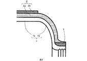
図1は本発明の高圧ガス貯蔵容器11の一部破断部を有する全体図である。図1において、1は高圧ガス貯蔵容器11の内層をなすガスバリア性を有するライナーであり、円筒状の胴部1aと、その両端を閉鎖する湾曲面状の鏡部1bとから形成されている。2は繊維強化樹脂層であり、強化繊維が両端の鏡部1bにかかるように軸方向にヘリカル巻きされたヘリカル層2aと、強化繊維が胴部1aの周りに軸回り方向にフープ巻きされたフープ層2bとを含み、強化繊維はマトリックス樹脂で含浸固定されている。3は口金部であり、容器完成後には充填ガスを流入・流出させる口となり、さらに圧力計やバルブなどの付属品が取り付けられる場合もある。4が本発明の特徴である口金部補強構造の一例である。
【0011】
図2〜6は本発明の特徴である口金部補強構造の具体例の部分拡大図である。図2〜5は口金部補強構造としてリングを採用したものであり、図2は金属製リング5、図3は繊維強化樹脂層製リング6、図4は口金部補強構造外側のライナー1と接する側に周方向の溝7aを有するリング7、図5はライナー形状に沿うリブ8aを設けたリング8である。図6は直接口金部に口金部軸周り方向にフープ巻きで積層した繊維強化樹脂層9を口金部補強構造として採用したものである。
【0012】
これら種々の口金部補強構造を各図面に従って説明する。
【0013】
図2の金属製リング5は、以下に述べる材料によって作られるものである。
【0014】
低炭素鋼材、中炭素鋼材、高炭素鋼材などの炭素鋼、高張力鋼材、機械構造用マンガン鋼鋼材、マンガンクロム鋼鋼材などのマンガン鋼、ニッケルクロムモリブデン鋼鋼材、クロムモリブデン鋼鋼材などのクロムモリブデン鋼、ステンレス鋼鍛鋼品、ステンレス鋼棒、熱間圧延ステンレス鋼板および鋼帯、冷間圧延ステンレス鋼板および鋼帯などのステンレス鋼である。また、本材料そのものを適用しても良いし、炭素鋼に対しては、焼きなまし、焼きならし、マンガン鋼に対しては、焼きならし、焼き入れ焼きもどし、クロムモリブデン鋼に対しては、焼き入れ焼きもどし、ステンレス鋼に対しては固溶化処理を施した材料を適用しても良い。金属製リング5の製造方法としては、プレス加工、絞り加工、曲げ加工と切削加工や溶接加工を組み合わせた加工方法を選定することが多く、生産性や寸法精度の観点からプレス加工や絞り加工と切削加工や溶接加工の組み合わせが好ましい。
【0015】
図3の繊維強化樹脂製リング6は、強化繊維6aとマトリックス樹脂6bにより構成されている。本発明に適用できる強化繊維6aとしては、ガラス繊維、炭素繊維、アラミド繊維などを例示できる。曲げ特性、強度の観点から、強化繊維単体の引張弾性率が50GPa〜700GPaのものが好ましく、比剛性の観点をも考慮すると、200GPa〜700GPaがより好ましく、コストパフォーマンスの観点をも考慮すると200GPa〜450GPaが最も好ましい。また、強化繊維の密度は、1.60〜3.00のものが好ましく、軽量化の観点から1.70〜2.00のものがより好ましく、コストパフォーマンスの面より1.70〜1.90のものが最も好ましい。更にまた、繊維径は、一本当たり5〜30μmのものが好ましく、取り扱い性の観点から5〜20μmのものがより好ましく、さらに軽量化の観点から、5〜10μmのものが最も好ましい。本発明の口金部補強構造は、これらの強化繊維を単体で用いても良いし、数種類の強化繊維を組み合わせて用いてもよい。その場合、軽量化や比強度、比弾性率の観点から、少なくとも、1つが炭素繊維であることが好ましい。また、強化繊維とマトリックス樹脂の割合を繊維強化樹脂層材料中の強化繊維の体積分率Vfで規定すると、剛性の観点からVf20%〜90%がこのましく、生産性や要求剛性の観点からVfが40%〜80%であることが好ましい。
【0016】
本発明に適用できるマトリックス樹脂6bとしては、熱硬化性樹脂であっても熱可塑性樹脂であってもよい。熱硬化性樹脂の場合、その主材は、エポキシ樹脂、不飽和ポリエステル樹脂、ビニルエステル樹脂、フェノール樹脂、ポリウレタン樹脂、シリコン樹脂などを例示することができ、1種類だけであっても、或いは2種類以上を混合して使用してもよい。これら熱硬化性樹脂をマトリックス樹脂に採用する場合、前記熱硬化性樹脂に適切な硬化剤や反応促進剤を添加することが可能である。熱可塑性樹脂の場合、その主材は、ポリエチレン樹脂、ポリプロピレン樹脂、ポリ塩化ビニル樹脂、ABS樹脂、ポリスチレン樹脂、AS樹脂、ポリアミド樹脂、ポリアセタール樹脂、ポリカーボネート樹脂、熱可塑性ポリエステル樹脂、PPS樹脂、フッ素樹脂、ポリエーテルイミド樹脂、ポリエーテルケトン樹脂、ポリイミド樹脂など例示でき、1種類だけであっても、或いは2種類以上を混合して使用してもよい。これら熱可塑性樹脂は単独でも、混合物でも、また共重合体であっても良い。混合物の場合には相溶化剤を併用しても良い。さらに、難燃剤として臭素系難燃剤、シリコン系難燃剤、赤燐などを加えても良い。
【0017】
繊維強化樹脂製リング6の製造方法としては、従来法のフィラメントワインディング(以下FW)法、テープワインディング(以下TW)法、シートワインディング(以下SW)法、ハンドレイアップ法、RTM法などを適用することができる。これら成形法のうち、単一の方法のみで成形してもよいし、2種類以上の成形法を組み合わせて成形しも良い。特性の発現性や生産性、成形性の観点から、FW法、TW法、SW法が好ましい。
【0018】
図4のリング7は、金属製リング7の外側のライナー1と接する側に周方向の溝7aを有するものである。ライナー1の形状によっては口金部3で巻かれるフープ巻きの強化繊維束がばらけることがあり、そうなると結果的に口金部の積層肉厚が増加し、このまま巻き続けると、繊維強化樹脂層が口金を越えてしまうことがある。溝7aを設けることでフープ巻き強化繊維束のばらけによる肉厚増加を抑えることができ、繊維強化樹脂層が口金長さを越えてしまうことを防止することができる。この溝7aの深さt(mm)はリング肉厚T(mm)と以下の関係をもつのが好ましい。
【0019】
t=α・T
ここでαは係数であり、0.01〜0.99の値をとる。製造上の観点から、0.05以上が好ましく、リング剛性の観点から、0.1以下がより好ましい。また、この溝7aの長さl(mm)はフープ巻きの積層数にもよるが、リング長さL(mm)と以下の関係をもつのが好ましい。
【0020】
l=β・L
ここでβは係数であり、0.01〜0.99の値をとる。製造上の観点から、0.03以上が好ましく、リング剛性の観点から、0.3以下がより好ましい。リング7の材料および製造方法は上述したリング5と同様でよい。
【0021】
図5のリング8は、金属製リング5にライナー1に沿うリブ8aを設けたものである。リブ8aは鏡部1bの剛性が足りない場合に補強部材として効果を発揮するものである。肉厚は外観上の観点から、10mm以内が好ましく、さらに胴部1aに近づくにつれ薄くなるのがより好ましい。長さは鏡部長さ以内なら特に規定されるものではない。リング8の材料および製造方法は上述したリング5と同様でよい。
【0022】
これらリング5〜8の外表面には、その上に巻かれる強化繊維の滑り止めとして、凹凸を設けてもよい。フライスなどで表面荒削り加工し、算術平均粗さRaで、3.2以上が好ましい。また、これらリング5〜8は、ライナーへ強化繊維を巻きつける前に口金部に取り付ける。すなわち、ライナー口金部に嵌め込み、その後、ライナーへ巻かれる強化繊維およびその後で含浸されるマトリックス樹脂によって固定する。また、金属製リングの場合は強化繊維を巻きつける前に焼きバメにより強固に固定することが可能である。
【0023】
図6の口金部補強構造9は、リング5〜8のようにリングを別体として製造せず、口金部に直接強化繊維を巻きつけ、口金部補強構造としたものである。材料は図3で説明したものと同様であり、ライナー口金部にフープ巻きにて強化繊維を巻きつけ、マトリックス樹脂にて含浸固定し製造する。この場合、口金部補強構造9の端部型崩れを防止するために、口金にリブ10を設けることが好ましい。リブ10は口金に溶接加工して設けてもよいし、リブをもつ薄い肉厚のリングを製作し、嵌め込んで設けることも可能である。その肉厚は5mm程度あれば十分である。
【0024】
これら口金部補強構造5〜9の剛性としては、曲げこわさ(EI)で2×10+8GPa・mm4以上が好ましく、肉厚Tは材料の剛性によるが10mm〜20mmが好ましく、外観の観点から、15mm以下することがより好ましい。そのため、材料剛性は200GPa以上が好ましい。長さLは、外観の観点から、ライナー口金と同じ長さが好ましい。
【0025】
このようにして口金部補強構造を有し、基本的な剛性、強度における設計によって製作された高圧ガス貯蔵容器に対して、その外装面に種々の塗装や装飾、金属メッキを施してもよく、また落下衝撃特性を向上させるために樹脂材料や金属材料で成形されたカバーを取り付けても良い。これら容器の外装面に設置することができる塗装や装飾や金属メッキやカバーなどの厚みや範囲、形状は特に限定されるものではない。
【0026】
【実施例】
次に実施例および比較例を示す。
【0027】
(実施例1)
本実施例では、図4に示す口金部補強構造として溝付きステンレス製リング7を採用した高圧ガス貯蔵容器を製作した。
【0028】
まず、容器本体として、ライナー1の直径380mm、その胴部長さ950mmの内容量100リットルのものを製造した。ライナー1は、アルミニウム合金6061-T6製でスピニング加工により製造し、胴部厚みは3mm、ガス流入出口は両端に各1個とした。溝付きステンレス製リング7は、SUS420をT:10mm、t:1mm、L:38mm、l:10mmとなるようにに切削加工し、焼きバメにより、口金部3に固定した。繊維強化樹脂層2として東レ(株)製炭素繊維“トレカ”M30S−18K−50Cからなる強化繊維にJER(株)製“エピコート”828のマトリックス樹脂を含浸させたものを、FW法によりフープ巻付角89度、ヘリカル巻付角10度でワインディングして被覆した。
【0029】
この高圧ガス貯蔵容器に対して、一方の口に栓をし、もう片方の口に水圧ポンプの加圧口を接続し、水圧により、最小破壊ガス充填圧力175MPaをかけた結果、口金部3付近の繊維強化樹脂層中の強化繊維に発生する応力は、ひずみゲージで測定した表層値から補間し算出したところ、最大1794MPaとなり、繊維強度規格を下回り、破壊には至らなかった。
【0030】
(実施例2)
実施例は、図4の溝付きステンレス製リング7に代えて、炭素繊維強化樹脂製リング6を口金部補強構造として採用したもので、その詳細図は図3のとおりである。実施例1と異なる点は上記した口金部補強構造のみであり、その他の構成は同様であり、図3中における符号1および2は図4と同じものである。炭素繊維強化樹脂製リング6を構成する各材料は、上述したライナー補強用繊維強化樹脂層2のそれぞれと同様であり、6aが強化繊維、6bがマトリックス樹脂である。このような材料により、FW法によりフープ巻きにて肉厚10mmの炭素繊維強化樹脂製パイプを製造し、長さ38mmに切り出すことで炭素繊維強化樹脂製リング6とし、口金部3にFW法により固定した。
【0031】
この高圧ガス貯蔵容器に対して、実施例1と同様の試験方法で最小破壊ガス充填圧力175MPaまで加圧したところ、口金部の繊維強化樹脂層中の強化繊維に発生する応力は最大1770MPaとなり、実施例1と同様に繊維強度規格を下回り、破壊には至らなかった。また、実施例1よりも口金部の繊維強化樹脂層中の強化繊維に発生する応力を低減することができた。
【0032】
(実施例3)
本実施例は、図3の炭素繊維強化樹脂製リング6に代えて、口金部に直接強化繊維を巻きつけたものを口金部補強構造9としたもので、その詳細図は図6のとおりである。実施例2と異なる点は上記した口金部補強構造と端部崩れ防止のリブ10であり、その他の構成は同様である。また、図6中における符号1および2についても図3と同様の部材を用いている。まず、容器本体の口金部3には、肉厚5mmのアルミニウム板を溶接することにより、リブ10を形成した。口金部補強構造9の材料は実施例2と同様であり、9aが強化繊維、9bがマトリックス樹脂で、ライナー1の外周面に繊維強化樹脂層2を巻き付ける前にFW法にて口金部用に89度に巻き角度を変更することにて形成した。
【0033】
この高圧ガス貯蔵容器に対して、実施例2と同様の試験方法で最小破壊ガス充填圧力175MPaまで加圧したところ、口金部の繊維強化樹脂層中の強化繊維に発生する応力は最大1810MPaとなり、繊維強度規格を下回り、破壊には至らなかった。また、本実施例は、実施例1および2のようにリングを別工程にて製造する必要がないため、容易に製造が可能であった。
【0034】
(比較例1)
次に、容器本体の口金部3の肉厚を10mmとして口金部補強構造4のみがなく、他は実施例1で述べたのと同じ構造の容器を製作した。この容器に対し、実施例3と同様の水圧試験方法で最小破壊ガス充填圧力175MPaまで加圧しようとしたところ、100MPa加圧時点で口金部の繊維強化樹脂中の強化繊維に発生する応力が繊維強度規格となったため、試験を中止した。試験結果から、最小破壊ガス充填圧力175MPa加圧時の口金部の繊維強化樹脂層中の強化繊維に発生する応力は最大4130MPaと推定でき、このまま加圧を続行すれば繊維強度規格を上回るため破壊に至ることになる。
【0035】
上述した実施例および比較例を纏めたのが次の表1である。
【0036】
【表1】
【0037】
【発明の効果】
本発明の高圧ガス貯蔵容器は、高圧ガス容器本体の口金部に、リングや繊維強化樹脂層からなる口金部補強構造を設けたので、口金部付近の繊維強化樹脂層中の強化繊維に発生する応力を低減することができ、その結果高圧に耐えうる高圧ガス貯蔵容器を製造することができる。
【図面の簡単な説明】
【図1】本発明の高圧ガス貯蔵容器の一部破断面を有する全体図である。
【図2】口金部補強構造として金属製リングを取り付けた本発明の高圧ガス貯蔵容器の口金部断面図である。
【図3】口金部補強構造として繊維強化樹脂層製リングを取り付けた本発明の高圧ガス貯蔵容器の口金部断面図である。
【図4】口金部補強構造として周方向に溝を設けた金属製リングを取り付けた本発明の高圧ガス貯蔵容器の口金部断面図である。
【図5】口金部補強構造としてライナー形状に沿うリブを設けた金属製リングを取り付けた本発明の高圧ガス貯蔵容器の口金部断面図である。
【図6】口金部補強構造として直接口金部に繊維強化樹脂層を口金部周方向へフープ積層した本発明の高圧ガス貯蔵容器の口金部断面図である。
【符号の説明】
1 :ライナー
1a :ライナー胴部
1b :ライナー鏡部
2 :繊維強化樹脂層
2a :ヘリカル巻き繊維強化樹脂層
2b :フープ巻き繊維強化樹脂層
3 :口金部
4 :口金部補強構造
5 :口金部補強構造(金属製リング)
6 :口金部補強構造(繊維強化樹脂層製リング)
6a :口金部補強構造6を構成する強化繊維
6b :口金部補強構造6を構成するマトリックス樹脂
7 :口金部補強構造(溝を設けた金属製リング)
8 :口金部補強構造(リブを設けた金属製リング)
9 :口金部補強構造(口金部に繊維強化樹脂層を口金部周方向へフー プ積層した補強構造)
9a :口金部補強構造9を構成する強化繊維
9b :口金部補強構造9を構成するマトリックス樹脂
10 :口金端部に設けたリブ
11 :高圧ガス貯蔵容器[0001]
TECHNICAL FIELD OF THE INVENTION
The present invention provides a high-pressure gas storage container that stores gas in a high-pressure state, and reduces stress generated in reinforcing fibers in a fiber-reinforced resin layer near a mouth portion that is a gas inlet / outlet. And a high-pressure gas storage container having:
[0002]
[Prior art]
In recent years, the development of fuel cell vehicles has rapidly progressed at automakers, and various issues have been accumulated in the development. One of the most difficult issues is how to supply and store pure hydrogen as a fuel source. Have been.
Regarding the storage of this pure hydrogen, it is necessary to solve problems such as the total weight including the container, installation space, and safety, and various methods are being studied. Examples include a high-pressure gas storage container, a hydrogen storage alloy, liquid hydrogen, a chemical hydride, a carbon nanotube, and the like. Of these, the most important is the high-pressure gas storage container.
[0003]
Manufacturers of high-pressure gas storage containers are developing fiber-reinforced materials from the viewpoint of weight reduction and space saving.At present, the maximum filling pressure level of the container is 35MPa. It is low and has a low capacity of about 100 liters, so it can withstand only about 300 km of actual mileage, and it can not withstand the desired actual mileage of about 500 km required for one hydrogen supply . In order to extend this actual traveling distance, it is necessary to increase the amount of hydrogen that can be charged, and for that purpose, it is necessary to raise the operational filling pressure level of the container.
[0004]
However, it is difficult to cope with the application of the conventional technology such as the design of the reinforcing fiber layer in the fiber-reinforced resin layer, and each container maker is struggling. Specifically, the deformation state of the container is different under high-pressure filling, and the mouth part of the gas inlet / outlet is deformed in the circumferential direction. Therefore, in the same laminated design as the low filling pressure vessel, the reinforcing fibers in the fiber reinforced resin layer of the mouth part It is very likely that high stress will be generated on the base and breakage will occur from the base. Therefore, as a general countermeasure, it is conceivable to increase the number of reinforcing fibers laminated in the base portion and reinforce it.For example, in a commonly used filament winding method, the number of laminated body portions also increases at the same time. And the stress balance of the base part does not change much, and as a result, the lamination of the body part is over-specified and the cost is increased. In addition, when the number of laminated reinforcing fibers in the base is increased, the axial length of the base is eventually increased, which is not preferable in terms of appearance and installation space. As a solution to such a problem of the base portion, Patent Literature 1 discloses that a shaft is arranged inside a tank in a direction along a tank axis, and the base portions located at both ends are connected to each other to prevent breakage of the base portion. Although a method has been proposed, it attempts to prevent destruction by suppressing axial deformation and is not effective for circumferential deformation under high pressure filling.
[0005]
As described above, in the case of a high filling pressure vessel in which the operating filling pressure is, for example, 70 MPa or more, there is a problem that the structure of the mouthpiece becomes important and the design of the low filling pressure vessel cannot be applied as it is.
[0006]
[Reference 1]
JP-A-9-112796 (page 5, FIG. 1)
[0007]
[Problems to be solved by the invention]
The present invention solves the above-described problems of the prior art, reduces the stress generated in the reinforcing fibers in the fiber reinforced resin layer near the mouthpiece portion of the inlet and outlet of the high-pressure gas, and allows high-pressure filling at an operating filling pressure of 70 MPa or more. The aim is to propose a possible high pressure gas storage container.
[0008]
[Means for Solving the Problems]
In order to achieve the above object, a high-pressure gas storage container according to the present invention includes an airtight container main body, and at least one port through which high-pressure gas flows into and out of the container main body. A high-pressure gas storage container comprising a liner directly in contact with gas and a fiber reinforced resin layer disposed on an outer peripheral surface of the liner, wherein the high-pressure gas storage container has a reinforcing structure on an outer peripheral surface of the mouthpiece. Things.
[0009]
BEST MODE FOR CARRYING OUT THE INVENTION
Hereinafter, the contents of the present invention will be described with reference to the drawings of one embodiment of the present invention.
[0010]
FIG. 1 is an overall view of a high-pressure gas storage container 11 of the present invention with a partially broken portion. In FIG. 1, reference numeral 1 denotes a liner having a gas barrier property as an inner layer of the high-pressure gas storage container 11, which is formed of a cylindrical body 1a and a curved mirror 1b closing both ends thereof. Reference numeral 2 denotes a fiber reinforced resin layer, in which a helical layer 2a in which reinforced fibers are helically wound in the axial direction so as to cover the mirror portions 1b at both ends, and a reinforced fiber in which the reinforcing fibers are hoop-wrapped around the body 1a in the direction around the axis. And a reinforcing fiber is impregnated and fixed with a matrix resin. Reference numeral 3 denotes a cap portion, which serves as a port for inflow / outflow of the filling gas after completion of the container, and may further include accessories such as a pressure gauge and a valve. Reference numeral 4 denotes an example of a base part reinforcing structure which is a feature of the present invention.
[0011]
2 to 6 are partially enlarged views of a specific example of a base part reinforcing structure which is a feature of the present invention. 2 to 5 show a case where a ring is adopted as a base part reinforcing structure. FIG. 2 shows a metal ring 5, FIG. 3 shows a fiber reinforced resin layer ring 6, and FIG. 4 shows a liner 1 outside a base part reinforcing structure. A ring 7 having a circumferential groove 7a on the side, and FIG. 5 shows a ring 8 provided with a rib 8a along the liner shape. FIG. 6 shows an example in which a fiber reinforced resin layer 9 directly laminated on a base portion by hoop winding in a direction around the base portion axis is employed as a base portion reinforcing structure.
[0012]
These various types of base member reinforcing structures will be described with reference to the drawings.
[0013]
The metal ring 5 shown in FIG. 2 is made of a material described below.
[0014]
Low carbon steel, medium carbon steel, high carbon steel, etc., carbon steel, high tensile steel, manganese steel for machine structure, manganese steel such as manganese chromium steel, chromium molybdenum steel such as nickel chromium molybdenum steel, chromium molybdenum steel Stainless steel such as steel, stainless steel forgings, stainless steel bars, hot rolled stainless steel plates and strips, cold rolled stainless steel plates and strips. In addition, this material itself may be applied, or for carbon steel, annealing and normalizing, for manganese steel, normalizing and quenching and tempering, and for chromium molybdenum steel, A material that has been subjected to solution treatment for quenched and tempered stainless steel may be used. As a method of manufacturing the metal ring 5, a processing method that combines pressing, drawing, bending, cutting, and welding is often selected. From the viewpoint of productivity and dimensional accuracy, pressing and drawing are used. A combination of cutting and welding is preferred.
[0015]
The fiber reinforced resin ring 6 shown in FIG. 3 is composed of reinforced fibers 6a and a matrix resin 6b. Examples of the reinforcing fibers 6a applicable to the present invention include glass fibers, carbon fibers, and aramid fibers. From the viewpoint of bending characteristics and strength, the tensile modulus of the reinforcing fiber alone is preferably 50 GPa to 700 GPa.From the viewpoint of specific rigidity, 200 GPa to 700 GPa is more preferable, and also from the viewpoint of cost performance, 200 GPa to 200 GPa. 450 GPa is most preferred. The density of the reinforcing fibers is preferably 1.60 to 3.00, more preferably 1.70 to 2.00 from the viewpoint of weight reduction, and most preferably 1.70 to 1.90 from the viewpoint of cost performance. Further, the fiber diameter is preferably 5 to 30 μm per fiber, more preferably 5 to 20 μm from the viewpoint of handleability, and most preferably 5 to 10 μm from the viewpoint of weight reduction. In the mouthpiece reinforcing structure of the present invention, these reinforcing fibers may be used alone or in combination of several types of reinforcing fibers. In that case, it is preferable that at least one is a carbon fiber from the viewpoint of weight reduction, specific strength, and specific elastic modulus. When the ratio of the reinforcing fiber and the matrix resin is defined by the volume fraction Vf of the reinforcing fiber in the fiber-reinforced resin layer material, Vf 20% to 90% is preferable from the viewpoint of rigidity, and from the viewpoint of productivity and required rigidity. Vf is preferably 40% to 80%.
[0016]
The matrix resin 6b applicable to the present invention may be a thermosetting resin or a thermoplastic resin. In the case of a thermosetting resin, its main material can be exemplified by an epoxy resin, an unsaturated polyester resin, a vinyl ester resin, a phenol resin, a polyurethane resin, a silicone resin, and the like. More than one kind may be mixed and used. When these thermosetting resins are used for the matrix resin, it is possible to add an appropriate curing agent or reaction accelerator to the thermosetting resin. In the case of thermoplastic resin, the main materials are polyethylene resin, polypropylene resin, polyvinyl chloride resin, ABS resin, polystyrene resin, AS resin, polyamide resin, polyacetal resin, polycarbonate resin, thermoplastic polyester resin, PPS resin, fluorine resin Examples thereof include polyether imide resin, polyether ketone resin, and polyimide resin. One type may be used alone, or two or more types may be used in combination. These thermoplastic resins may be used alone, as a mixture, or as a copolymer. In the case of a mixture, a compatibilizer may be used in combination. Further, bromine-based flame retardants, silicon-based flame retardants, red phosphorus and the like may be added as flame retardants.
[0017]
As a method of manufacturing the fiber-reinforced resin ring 6, a conventional method such as a filament winding (hereinafter, FW) method, a tape winding (hereinafter, TW) method, a sheet winding (hereinafter, SW) method, a hand lay-up method, an RTM method, or the like is applied. be able to. Of these molding methods, molding may be performed by a single method alone, or by combining two or more types of molding methods. The FW method, the TW method, and the SW method are preferred from the viewpoints of property development, productivity, and moldability.
[0018]
The ring 7 shown in FIG. 4 has a circumferential groove 7a on the outer side of the metal ring 7 in contact with the liner 1. Depending on the shape of the liner 1, the hoop-wound reinforcing fiber bundle wound around the base 3 may come apart, which results in an increase in the laminated thickness of the base. May be exceeded. By providing the groove 7a, it is possible to suppress an increase in wall thickness due to the dispersion of the hoop-wound reinforcing fiber bundle, and to prevent the fiber-reinforced resin layer from exceeding the length of the die. The depth t (mm) of the groove 7a preferably has the following relationship with the ring thickness T (mm).
[0019]
t = α · T
Here, α is a coefficient and takes a value of 0.01 to 0.99. From the viewpoint of manufacturing, the value is preferably 0.05 or more, and from the viewpoint of ring rigidity, 0.1 or less is more preferable. The length 1 (mm) of the groove 7a depends on the number of hoop windings, but preferably has the following relationship with the ring length L (mm).
[0020]
l = β · L
Here, β is a coefficient and takes a value of 0.01 to 0.99. 0.03 or more is preferable from a viewpoint of manufacture, and 0.3 or less is more preferable from a viewpoint of ring rigidity. The material and manufacturing method of the ring 7 may be the same as the ring 5 described above.
[0021]
The ring 8 shown in FIG. 5 is obtained by providing a metal ring 5 with a rib 8 a along the liner 1. The rib 8a is effective as a reinforcing member when the rigidity of the mirror portion 1b is insufficient. The thickness is preferably within 10 mm from the viewpoint of appearance, and more preferably the thickness becomes thinner as approaching the body 1a. The length is not particularly limited as long as it is within the mirror length. The material and manufacturing method of the ring 8 may be the same as the ring 5 described above.
[0022]
The outer surfaces of the rings 5 to 8 may be provided with irregularities as slip stoppers for the reinforcing fibers wound thereon. The surface is roughened with a milling machine, and the arithmetic average roughness Ra is preferably 3.2 or more. These rings 5 to 8 are attached to the base before the reinforcing fibers are wound around the liner. That is, it is fitted into the liner base and then fixed by the reinforcing fibers wound around the liner and the matrix resin impregnated thereafter. In the case of a metal ring, it is possible to firmly fix the ring by baking before winding the reinforcing fiber.
[0023]
The base-portion reinforcing structure 9 shown in FIG. 6 has a base-portion reinforcing structure in which a reinforcing fiber is directly wound around the base portion without manufacturing the ring as a separate body like the rings 5 to 8. The material is the same as that described with reference to FIG. 3. The reinforcing fiber is wound around the liner base with a hoop, and impregnated and fixed with a matrix resin. In this case, it is preferable to provide the base with a rib 10 in order to prevent the end portion of the base section reinforcing structure 9 from collapsing. The rib 10 may be provided on the base by welding, or a thin-walled ring having a rib may be manufactured and fitted and provided. A thickness of about 5 mm is sufficient.
[0024]
The rigidity of these mouthpiece reinforcing structures 5 to 9 is preferably 2 × 10 + 8 GPa · mm 4 or more in terms of bending stiffness (EI), and the thickness T is preferably 10 mm to 20 mm, depending on the rigidity of the material. , 15 mm or less is more preferable. Therefore, the material rigidity is preferably 200 GPa or more. The length L is preferably the same as the length of the liner cap from the viewpoint of appearance.
[0025]
The high-pressure gas storage container having the base portion reinforcing structure in this manner, and having a basic rigidity and strength, may be subjected to various coatings, decorations, and metal plating on its exterior surface, Further, a cover formed of a resin material or a metal material may be attached to improve the drop impact characteristics. The thickness, range, and shape of the coating, decoration, metal plating, cover, and the like that can be installed on the exterior surface of these containers are not particularly limited.
[0026]
【Example】
Next, examples and comparative examples will be described.
[0027]
(Example 1)
In the present embodiment, a high-pressure gas storage container employing a grooved stainless steel ring 7 as the mouthpiece reinforcing structure shown in FIG. 4 was manufactured.
[0028]
First, as the container body, a liner 1 having a diameter of 380 mm and a body length of 950 mm and a capacity of 100 liters was manufactured. The liner 1 was made of aluminum alloy 6061-T6 by spinning, had a body thickness of 3 mm, and one gas inlet / outlet at each end. The grooved stainless steel ring 7 was formed by cutting SUS420 so that T: 10 mm, t: 1 mm, L: 38 mm, and l: 10 mm, and fixed to the base 3 by shrink fitting. The fiber reinforced resin layer 2 is obtained by impregnating a matrix fiber of “Epicoat” 828 manufactured by JER Co., Ltd. into a reinforcing fiber made of carbon fiber “Torayca” M30S-18K-50C manufactured by Toray Co., Ltd. Coating was performed at a winding angle of 89 degrees and a helical winding angle of 10 degrees.
[0029]
This high-pressure gas storage container was plugged in one port and connected to the pressurizing port of a water pressure pump in the other port. As a result of applying a minimum destructive gas filling pressure of 175 MPa by water pressure, the vicinity of the base 3 The stress generated in the reinforcing fibers in the fiber reinforced resin layer of the above was calculated by interpolating from the surface layer value measured by a strain gauge, and was a maximum of 1794 MPa, which was lower than the fiber strength standard and did not lead to destruction.
[0030]
(Example 2)
In the embodiment, a ring 6 made of carbon fiber reinforced resin is adopted as a mouthpiece reinforcing structure in place of the grooved stainless steel ring 7 of FIG. 4, and its detailed view is as shown in FIG. The only difference from the first embodiment is the above-described base reinforcing structure. Other configurations are the same, and reference numerals 1 and 2 in FIG. 3 are the same as those in FIG. The materials constituting the carbon fiber reinforced resin ring 6 are the same as those of the liner reinforcing fiber reinforced resin layer 2 described above, wherein 6a is a reinforcing fiber and 6b is a matrix resin. With such a material, a carbon fiber reinforced resin pipe having a thickness of 10 mm is manufactured by hoop winding by the FW method, and is cut into a length of 38 mm to form a carbon fiber reinforced resin ring 6. Fixed.
[0031]
When this high-pressure gas storage container was pressurized to the minimum breaking gas filling pressure of 175 MPa by the same test method as in Example 1, the stress generated in the reinforcing fibers in the fiber-reinforced resin layer of the mouthpiece became 1770 MPa at maximum, As in the case of Example 1, the value was lower than the fiber strength standard and did not result in destruction. In addition, the stress generated in the reinforcing fibers in the fiber reinforced resin layer of the base was able to be reduced as compared with Example 1.
[0032]
(Example 3)
In this embodiment, instead of the carbon fiber reinforced resin ring 6 shown in FIG. 3, a reinforced fiber is wound directly around a base to form a base reinforcing structure 9, and its detailed view is as shown in FIG. is there. The difference from the second embodiment is the above-described base portion reinforcing structure and the rib 10 for preventing the end portion from collapsing, and the other configurations are the same. Further, members similar to those in FIG. 3 are used for reference numerals 1 and 2 in FIG. First, a rib 10 was formed on the base 3 of the container body by welding an aluminum plate having a thickness of 5 mm. The material of the base part reinforcing structure 9 is the same as that of the second embodiment, 9a is a reinforcing fiber, 9b is a matrix resin, and before the fiber reinforced resin layer 2 is wound around the outer peripheral surface of the liner 1, the base material is formed by the FW method. It was formed by changing the winding angle to 89 degrees.
[0033]
When this high-pressure gas storage container was pressurized to the minimum breaking gas filling pressure of 175 MPa by the same test method as in Example 2, the stress generated in the reinforcing fibers in the fiber reinforced resin layer of the mouthpiece became 1810 MPa at maximum, It was below the fiber strength standard and did not break. Further, in this embodiment, it was not necessary to manufacture the ring in a separate step as in the first and second embodiments, so that the manufacture was easy.
[0034]
(Comparative Example 1)
Next, a container having the same structure as that described in Example 1 except that only the base part reinforcing structure 4 was provided with the thickness of the base part 3 of the container body being 10 mm was provided. When it was attempted to pressurize this container to the minimum breaking gas filling pressure of 175 MPa by the same hydraulic test method as in Example 3, the stress generated in the reinforcing fibers in the fiber-reinforced resin in the mouthpiece at the time of pressurizing 100 MPa was The test was stopped because the strength standard was reached. From the test results, the stress generated in the reinforcing fibers in the fiber reinforced resin layer of the mouthpiece when the minimum breaking gas filling pressure is 175MPa is estimated to be 4130MPa at the maximum. Will be reached.
[0035]
Table 1 below summarizes the above-described examples and comparative examples.
[0036]
[Table 1]
[0037]
【The invention's effect】
In the high-pressure gas storage container of the present invention, since the base portion of the high-pressure gas container body is provided with a base portion reinforcing structure including a ring and a fiber-reinforced resin layer, the high-pressure gas storage container is generated in the reinforcing fibers in the fiber-reinforced resin layer near the base portion. Stress can be reduced, and as a result, a high-pressure gas storage container that can withstand high pressure can be manufactured.
[Brief description of the drawings]
FIG. 1 is an overall view of a high-pressure gas storage container of the present invention having a partially broken surface.
FIG. 2 is a sectional view of a base of the high-pressure gas storage container of the present invention, in which a metal ring is mounted as a base reinforcing structure.
FIG. 3 is a cross-sectional view of a base portion of the high-pressure gas storage container of the present invention to which a ring made of a fiber reinforced resin layer is attached as a base portion reinforcing structure.
FIG. 4 is a sectional view of a high-pressure gas storage container according to the present invention to which a metal ring provided with a groove in the circumferential direction as a base reinforcing structure is attached.
FIG. 5 is a cross-sectional view of a base portion of the high-pressure gas storage container of the present invention to which a metal ring provided with a rib along the liner shape as a base portion reinforcing structure is attached.
FIG. 6 is a cross-sectional view of a high-pressure gas storage container according to the present invention in which a fiber-reinforced resin layer is directly hoop-stacked on the base in the circumferential direction of the base as a base reinforcing structure.
[Explanation of symbols]
1: liner 1a: liner body 1b: liner mirror 2: fiber reinforced resin layer 2a: helical wrapped fiber reinforced resin layer 2b: hoop wrapped fiber reinforced resin layer 3: base 4: base reinforced structure 5: base reinforced Structure (metal ring)
6: Reinforcement structure (ring made of fiber reinforced resin layer)
6a: Reinforcing fiber 6b forming base part reinforcing structure 6: Matrix resin forming base part reinforcing structure 6: Base part reinforcing structure (metal ring provided with groove)
8: Reinforcement structure (metal ring with ribs)
9: Reinforcement structure of the base part (reinforcement structure in which a fiber reinforced resin layer is laminated on the base part in the circumferential direction of the base part)
9a: Reinforcing fiber 9b constituting base part reinforcing structure 9: Matrix resin constituting base part reinforcing structure 9: Rib provided at end of base part 11: High pressure gas storage container