EP1657765A2 - Sicherheitseinrichtung für eine Batterie - Google Patents
Sicherheitseinrichtung für eine Batterie Download PDFInfo
- Publication number
- EP1657765A2 EP1657765A2 EP05024460A EP05024460A EP1657765A2 EP 1657765 A2 EP1657765 A2 EP 1657765A2 EP 05024460 A EP05024460 A EP 05024460A EP 05024460 A EP05024460 A EP 05024460A EP 1657765 A2 EP1657765 A2 EP 1657765A2
- Authority
- EP
- European Patent Office
- Prior art keywords
- pressure
- cell
- battery
- releasing unit
- pressure releasing
- Prior art date
- Legal status (The legal status is an assumption and is not a legal conclusion. Google has not performed a legal analysis and makes no representation as to the accuracy of the status listed.)
- Granted
Links
Images



Classifications
-
- H—ELECTRICITY
- H01—ELECTRIC ELEMENTS
- H01M—PROCESSES OR MEANS, e.g. BATTERIES, FOR THE DIRECT CONVERSION OF CHEMICAL ENERGY INTO ELECTRICAL ENERGY
- H01M10/00—Secondary cells; Manufacture thereof
- H01M10/04—Construction or manufacture in general
- H01M10/0436—Small-sized flat cells or batteries for portable equipment
-
- H—ELECTRICITY
- H01—ELECTRIC ELEMENTS
- H01M—PROCESSES OR MEANS, e.g. BATTERIES, FOR THE DIRECT CONVERSION OF CHEMICAL ENERGY INTO ELECTRICAL ENERGY
- H01M50/00—Constructional details or processes of manufacture of the non-active parts of electrochemical cells other than fuel cells, e.g. hybrid cells
- H01M50/30—Arrangements for facilitating escape of gases
- H01M50/342—Non-re-sealable arrangements
- H01M50/3425—Non-re-sealable arrangements in the form of rupturable membranes or weakened parts, e.g. pierced with the aid of a sharp member
-
- H—ELECTRICITY
- H01—ELECTRIC ELEMENTS
- H01M—PROCESSES OR MEANS, e.g. BATTERIES, FOR THE DIRECT CONVERSION OF CHEMICAL ENERGY INTO ELECTRICAL ENERGY
- H01M50/00—Constructional details or processes of manufacture of the non-active parts of electrochemical cells other than fuel cells, e.g. hybrid cells
- H01M50/30—Arrangements for facilitating escape of gases
- H01M50/383—Flame arresting or ignition-preventing means
-
- H—ELECTRICITY
- H01—ELECTRIC ELEMENTS
- H01M—PROCESSES OR MEANS, e.g. BATTERIES, FOR THE DIRECT CONVERSION OF CHEMICAL ENERGY INTO ELECTRICAL ENERGY
- H01M10/00—Secondary cells; Manufacture thereof
- H01M10/05—Accumulators with non-aqueous electrolyte
- H01M10/052—Li-accumulators
-
- H—ELECTRICITY
- H01—ELECTRIC ELEMENTS
- H01M—PROCESSES OR MEANS, e.g. BATTERIES, FOR THE DIRECT CONVERSION OF CHEMICAL ENERGY INTO ELECTRICAL ENERGY
- H01M10/00—Secondary cells; Manufacture thereof
- H01M10/42—Methods or arrangements for servicing or maintenance of secondary cells or secondary half-cells
- H01M10/425—Structural combination with electronic components, e.g. electronic circuits integrated to the outside of the casing
-
- Y—GENERAL TAGGING OF NEW TECHNOLOGICAL DEVELOPMENTS; GENERAL TAGGING OF CROSS-SECTIONAL TECHNOLOGIES SPANNING OVER SEVERAL SECTIONS OF THE IPC; TECHNICAL SUBJECTS COVERED BY FORMER USPC CROSS-REFERENCE ART COLLECTIONS [XRACs] AND DIGESTS
- Y02—TECHNOLOGIES OR APPLICATIONS FOR MITIGATION OR ADAPTATION AGAINST CLIMATE CHANGE
- Y02E—REDUCTION OF GREENHOUSE GAS [GHG] EMISSIONS, RELATED TO ENERGY GENERATION, TRANSMISSION OR DISTRIBUTION
- Y02E60/00—Enabling technologies; Technologies with a potential or indirect contribution to GHG emissions mitigation
- Y02E60/10—Energy storage using batteries
-
- Y—GENERAL TAGGING OF NEW TECHNOLOGICAL DEVELOPMENTS; GENERAL TAGGING OF CROSS-SECTIONAL TECHNOLOGIES SPANNING OVER SEVERAL SECTIONS OF THE IPC; TECHNICAL SUBJECTS COVERED BY FORMER USPC CROSS-REFERENCE ART COLLECTIONS [XRACs] AND DIGESTS
- Y02—TECHNOLOGIES OR APPLICATIONS FOR MITIGATION OR ADAPTATION AGAINST CLIMATE CHANGE
- Y02P—CLIMATE CHANGE MITIGATION TECHNOLOGIES IN THE PRODUCTION OR PROCESSING OF GOODS
- Y02P70/00—Climate change mitigation technologies in the production process for final industrial or consumer products
- Y02P70/50—Manufacturing or production processes characterised by the final manufactured product
Definitions
- the present invention relates to a battery of a mobile terminal, and more particularly to a safety device for a battery that improves the safety of the battery by smoothly releasing an internal pressure of the battery when the internal pressure of the battery exceeds a predetermined pressure.
- a mobile communication terminal can be carried with a user allowing him or her to call another party while moving about. Further, the mobile terminal generally includes a detachable battery for supplying power to the terminal. The battery can also be recharged after it has been used for a certain period of time to thereby reuse the battery.
- a mobile terminal battery is commonly a lithium battery.
- lithium ions are generated by oxidation from poles formed of lithium oxide, and the lithium ions move through an electrolyte and are reduced by reduction from a negative pole formed of material such as carbon or the like, thereby generating electric energy. The generated electric energy is then used to operate the mobile terminal.
- Figure 1 is a perspective view illustrating one example of a related art battery
- Figure 2 is a perspective illustrating the related battery without a cover member.
- the related art battery includes a hexahedral-shaped cell 100 filled with an electrolyte or the like, and a protection circuit assembly 200 connected to one side of the cell 100.
- the protection circuit assembly 200 stabilizes a current within the cell 100 when electric discharge or recharge occurs within the cell.
- a cover member 300 surrounding and protecting the protection circuit assembly 200 and reinforcing a coupling force between the protection circuit.assembly 200 and the cell 100.
- the cell 100 is formed of an aluminum material and is hermetically sealed.
- the protection circuit assembly 200 also include terminals 210 respectively connected to a terminal portion of the cell 100.
- the cover member 300 is formed using a low temperature, lower pressure injection method with resin, such as a synthetic resin of a nylon series, after the protection circuit assembly 200 is connected to the cell 100.
- the cell 100 is provided with a pressure releasing portion 110 for releasing the internal pressure when the pressure of the cell 100 exceeds a set pressure.
- the releasing portion 110 is provided on a side surface of the cell 100.
- the releasing portion 110 is coupled with the protection circuit assembly 200, and has a certain area and a thickness that is smaller than other portions of the cell 100. Namely, the pressure releasing portion 110 is formed via a groove with a certain area and depth formed in one side of the cell 100.
- the molten injection material of the cover member 300 is filled in the groove forming the pressure releasing portion 110 and is solidified in an injection molding process to tightly couple the cell 100 and the protection circuit assembly 200 and to encompass the protection circuit assembly 200.
- the cover member 300 blocks the pressure releasing portion 110.
- the pressure releasing portion 110 is not normally operated (i.e., is not easily torn), which may cause the cell 100 to explode.
- one object of the present invention is to address the above-noted and other problems.
- Another object of the present invention is to provide a safety device that improves the safety of the battery by smoothly releasing the internal pressure of the battery when the internal pressure reaches or exceeds a predetermined set pressure.
- the safety device includes a pressure releasing unit provided at a cell of the battery, in which the pressure releasing unit is configured to release an internal pressure within the cell when the internal pressure of the cell exceeds a predetermined set pressure. Also included is a space member covering the pressure releasing unit and configured to form an empty space around the pressure releasing unit such that when the internal pressure of the cell exceeds the predetermined set pressure, the released internal pressure is released into the empty space formed by the space member.
- a battery for a mobile communication terminal including a battery cell configured to provide a power source for the mobile terminal, a protection circuit assembly attached to a surface of the battery cell and configured to stabilize the power source within the battery cell when the battery is charged or discharged and a cover member configured to cover the protection circuit assembly and to couple the protection circuit assembly to the battery cell.
- a pressure releasing unit provided at a cell of the battery, in which the pressure releasing unit is configured to release an internal pressure within the cell when the internal pressure of the cell exceeds a predetermined set pressure, and a space forming member covering the pressure releasing unit and configured to form an empty space around the pressure releasing unit such that when the internal pressure of the cell exceeds the predetermined set pressure, the released internal pressure is released into the empty space formed by the space member.
- FIGs 5-7 illustrate a battery safety device according to the present invention.
- the battery includes a cell 400 filled with an electrolyte or the like, a protection circuit assembly 500 connected to one side of the cell 400, a cover member 600 covering and protecting the protection circuit assembly 500 and reinforcing a coupling force between the protection circuit assembly 500 and the cell 400, and a safety device 650 for releasing the internal pressure of the cell 400 when the internal pressure of the cell 400 exceeds a predetermined set pressure.
- the cell 400 has a hexahedral shape and is preferably made of aluminum.
- an electrolyte or the like is inserted into a can having one open side, and then the opened side of the can is covered with a plate.
- the plate may be bonded to the can by laser welding, etc.
- the cell 400 is in a hermetically closed state.
- the protection circuit assembly 500 includes terminals 510 respectively connected to a terminal portion (not shown) of the cell 400.
- the terminals 510 and the terminal portion of the cell 400 may be bonded together by spot welding, etc.
- the protection assembly 500 also stabilizes a current when the battery is charged and discharged.
- the cover member 600 is preferably formed using an injection-molding process with resin of a nylon series after the protection circuit assembly 500 is connected to the cell 400.
- Figure 6 illustrates the safety device 650 without the protection assembly 500 and the cover member 600.
- the safety device 650 shown in Figures 5 and 6 includes a pressure releasing unit 410 for releasing the internal pressure of the cell 400 when the internal pressure of the cell 400 exceeds a predetermined set pressure.
- the safety device 650 also includes a space forming cap 700 placed between the cell 400 and the cover member 600. The cap 700 covers the pressure releasing unit 410 and forms a space above the pressure releasing unit 410.
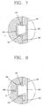
- the pressure releasing unit 410 includes a thin film portion 412 having a thickness smaller than other portions of the cell 400 and which is formed via a groove 411 having a predetermined area and depth. Also, the groove 411 is formed at an outer surface of the cell 400, and the pressure releasing unit 410 is provided on a surface of the cell 400 to which the protection circuit assembly 500 is coupled.
- the space forming cap 700 has a cap shape with an opened side and is provided above at the thin film portion 412 formed in the surface of the cell 400.
- the cap 700 forms a predetermined space above the pressure releasing unit 410.
- the cover member 600 is also coupled to encompass the space forming cap 700.
- One method of coupling the cover member 600 to the space forming cap 700 is as follows. First, the protection circuit assembly 500 is coupled to the front surface of the cell 400 and the space forming cap 700 is attached to the front surface of the cell 400 to cover the pressure releasing unit 410. Then, the cover member 600 is formed using a low temperature, low pressure injection method to encompass the protection circuit assembly 500 and the cell 400. Note, the space forming cap 700 prevents molten material from being introduced into the space covered by the cap 700. Insertion molding may also be used as another method of coupling the cover member 600 with the space forming cap 700.
- the space forming cap 700 is preferably formed of a material whose melting temperature is higher than that of the cover member 600.
- the cover member 600 may be formed of a synthetic resin of a nylon series
- the space forming cap 700 may be formed of a heat resistant synthetic resin, preferably LCP (Liquid Crystalline Polyester).
- LCP Liquid Crystalline Polyester
- the cap 700 may also be made using a metallic material.
- metallic material is generally more expensive than synthetic resin and is generally not able to be integrally coupled with the cover member 700, thereby possibly degrading the durability of the coupled member. Therefore, using synthetic resin is generally preferably because it is cheaper and can be integrally coupled with the cover member 600.
- the thin portion 412 of the pressure releasing unit 410 breaks or tears, thereby releasing the internal pressure into the space formed by the space forming cap 700.
- Figure 8 illustrates another embodiment of the invention in which a through hole (H) is provided through the cover member 600 and space forming cap 700. Further, an auxiliary pin 800 is inserted to thereby block the through hole (H).
- the pressure is released through the pressure releasing unit 410, and the auxiliary pin 800 is separated from the hole (H) because of the released pressure, thereby releasing the pressure to the outside of the battery.
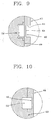
- Figure 9 illustrates another embodiment of the pressure releasing unit 410.
- the pressure releasing unit 410 includes a thin film portion 414 having a thickness smaller than other portions of the cell 400 and which is formed via a groove 413 formed at an inner wall of the cell 400.
- the groove 413 is formed at an inner surface of the cell 400 thereby forming the thin film portion 414.
- the thin film portion 414 is formed on an opposite side of the front surface of the cell 400 compared to the thin film portion 412 in Figure 7.
- Figure 10 illustrates another embodiment of the pressure releasing unit 410.
- Figure 10 illustrates the pressure releasing unit 410 including a space portion 610 formed in the cover member 600 and encompassing the protection circuit assembly 500. Further, the space portion 610 is placed at a portion facing the pressure releasing unit 410. Namely, the space portion 610 is formed in the cover member 600 without using the aforementioned space forming cap 700.
- the cover member 600 may also be formed by injection molding or may be formed as a separate member to be coupled to the cell 400.
- the battery provided with the battery safety device according to the present invention is detachably mounted to a mobile terminal or the like and is used as a power supply source. When the battery is totally discharged, the battery may be separated from the mobile terminal and recharged. Further, as shown in Figure 11, when the internal pressure in the cell 400 reaches or exceeds a predetermined set pressure (e.g., because the battery is over-charged or has been maintained at high temperature state), the thin portion 412 of the pressure releasing unit 410 breaks or tears and the pressure within the cell.400 is released into the space formed by the space forming cap 700 (or from the space portion 610).
- a predetermined set pressure e.g., because the battery is over-charged or has been maintained at high temperature state
- the pressure is released to the outside of the battery through the through hole (H) as the auxiliary pin 800 is separated from the through hole (H) by the released pressure.
- the cover member 600 when the cover member 600 is formed by an injection molding process, for example, after the space forming cap 700 is provided on the cell 400, an injection material for forming the cover member 600 does not block the pressure releasing unit 410 due to the space forming cap 700. Thus, because a predetermined space is formed above the pressure releasing unit 410, the pressure releasing unit 410 is not blocked and thus is accurately operated.
- the pressure releasing unit is accurately operated to release the pressure of the cell.
- the battery is prevented from exploding so that the reliability of the battery is improved and the user is protected from injury caused by the explosion of the battery.
Landscapes
- Chemical & Material Sciences (AREA)
- Chemical Kinetics & Catalysis (AREA)
- Electrochemistry (AREA)
- General Chemical & Material Sciences (AREA)
- Engineering & Computer Science (AREA)
- Manufacturing & Machinery (AREA)
- Gas Exhaust Devices For Batteries (AREA)
- Battery Mounting, Suspending (AREA)
- Sealing Battery Cases Or Jackets (AREA)
- Connection Of Batteries Or Terminals (AREA)
- Secondary Cells (AREA)
Applications Claiming Priority (1)
| Application Number | Priority Date | Filing Date | Title |
|---|---|---|---|
| KR1020040091614A KR100700564B1 (ko) | 2004-11-10 | 2004-11-10 | 배터리 및 이를 구비한 이동단말기 |
Publications (3)
| Publication Number | Publication Date |
|---|---|
| EP1657765A2 true EP1657765A2 (de) | 2006-05-17 |
| EP1657765A3 EP1657765A3 (de) | 2007-05-23 |
| EP1657765B1 EP1657765B1 (de) | 2015-10-28 |
Family
ID=35891289
Family Applications (1)
| Application Number | Title | Priority Date | Filing Date |
|---|---|---|---|
| EP05024460.7A Expired - Lifetime EP1657765B1 (de) | 2004-11-10 | 2005-11-09 | Sicherheitseinrichtung für eine Batterie |
Country Status (6)
| Country | Link |
|---|---|
| US (1) | US7662506B2 (de) |
| EP (1) | EP1657765B1 (de) |
| JP (1) | JP4464345B2 (de) |
| KR (1) | KR100700564B1 (de) |
| CN (1) | CN100414739C (de) |
| RU (1) | RU2315394C2 (de) |
Cited By (1)
| Publication number | Priority date | Publication date | Assignee | Title |
|---|---|---|---|---|
| EP2683001A1 (de) * | 2012-07-02 | 2014-01-08 | Optimum Battery Co., Ltd. | Kappenanordnung für Lithiumsekundärbatterie |
Families Citing this family (6)
| Publication number | Priority date | Publication date | Assignee | Title |
|---|---|---|---|---|
| US8720722B2 (en) * | 2005-12-15 | 2014-05-13 | Cornerstone Research Group, Inc. | Venting mechanism for containers |
| JP5291322B2 (ja) * | 2007-10-26 | 2013-09-18 | 日立マクセル株式会社 | 電池パック |
| US9293794B2 (en) | 2010-09-09 | 2016-03-22 | Panasonic intellectual property Management co., Ltd | Battery module |
| USD799425S1 (en) * | 2014-01-30 | 2017-10-10 | Nikon Corporation | Battery |
| USD820202S1 (en) * | 2016-07-26 | 2018-06-12 | Robert Bosch Gmbh | Housing for a battery |
| CN110391367B (zh) | 2019-08-08 | 2022-01-28 | 宁德时代新能源科技股份有限公司 | 二次电池的盖组件及二次电池 |
Family Cites Families (17)
| Publication number | Priority date | Publication date | Assignee | Title |
|---|---|---|---|---|
| RU1748588C (ru) * | 1990-05-07 | 1994-10-30 | Научно-производственное предприятие "Сатурн" | Корпус химического источника тока |
| ES2078046T3 (es) * | 1991-06-08 | 1995-12-01 | Busak & Shamban Gmbh & Co | Valvula de obturacion para aberturas de recipientes. |
| RU2050633C1 (ru) * | 1993-04-28 | 1995-12-20 | Производственно-коммерческое предприятие "Рискон" | Узел герметизации аккумулятора |
| EP0969536A3 (de) * | 1994-03-03 | 2003-10-08 | Japan Storage Battery Company Limited | Batterie |
| DE19527526A1 (de) * | 1995-07-27 | 1997-01-30 | Hagen Batterie Ag | Stopfenanordnung zum Verschließen einzelner Zellenöffnungen eines Akkumulators |
| KR970054707A (ko) * | 1995-12-22 | 1997-07-31 | 배순훈 | 리튬전지의 상부캡 구조 |
| KR970054709A (ko) * | 1995-12-30 | 1997-07-31 | 배순훈 | 측면개구형 방폭구조의 상부캡구비식 리튬전지 |
| JPH10247483A (ja) * | 1997-03-04 | 1998-09-14 | Mitsubishi Cable Ind Ltd | 密閉型電池の安全構造 |
| TW432737B (en) * | 1997-06-05 | 2001-05-01 | Toyo Kohan Co Ltd | Explosion-proof safety valve assemblage and closed secondary battery using it |
| JP2000082457A (ja) | 1998-09-04 | 2000-03-21 | Toyo Kohan Co Ltd | 電気電子機器・部品用安全装置、それを用いた密閉型電池の安全装置及びそれを用いた密閉型電池 |
| JP3906046B2 (ja) * | 2001-08-31 | 2007-04-18 | 三洋電機株式会社 | パック電池とその製造方法 |
| ITVI20010240A1 (it) | 2001-11-14 | 2003-05-14 | Franco Stocchiero | Gruppo valvolare di tenuta e di sfiato per accumulatori elettrici |
| JP4440548B2 (ja) * | 2002-02-13 | 2010-03-24 | パナソニック株式会社 | 電池とその製造方法 |
| JP4589596B2 (ja) * | 2002-03-22 | 2010-12-01 | パナソニック株式会社 | 電池パック |
| JP2004221025A (ja) | 2003-01-17 | 2004-08-05 | Hitachi Maxell Ltd | 電池 |
| US7195839B2 (en) * | 2003-02-11 | 2007-03-27 | Eveready Battery Company, Inc. | Battery cell with improved pressure relief vent |
| JP4130160B2 (ja) * | 2003-09-16 | 2008-08-06 | 三洋電機株式会社 | パック電池 |
-
2004
- 2004-11-10 KR KR1020040091614A patent/KR100700564B1/ko not_active Expired - Fee Related
-
2005
- 2005-11-02 JP JP2005319934A patent/JP4464345B2/ja not_active Expired - Fee Related
- 2005-11-07 RU RU2005134251/09A patent/RU2315394C2/ru not_active IP Right Cessation
- 2005-11-09 EP EP05024460.7A patent/EP1657765B1/de not_active Expired - Lifetime
- 2005-11-09 US US11/269,797 patent/US7662506B2/en not_active Expired - Fee Related
- 2005-11-10 CN CNB2005101250058A patent/CN100414739C/zh not_active Expired - Fee Related
Cited By (1)
| Publication number | Priority date | Publication date | Assignee | Title |
|---|---|---|---|---|
| EP2683001A1 (de) * | 2012-07-02 | 2014-01-08 | Optimum Battery Co., Ltd. | Kappenanordnung für Lithiumsekundärbatterie |
Also Published As
| Publication number | Publication date |
|---|---|
| JP4464345B2 (ja) | 2010-05-19 |
| US20060099491A1 (en) | 2006-05-11 |
| KR20060042820A (ko) | 2006-05-15 |
| KR100700564B1 (ko) | 2007-03-28 |
| US7662506B2 (en) | 2010-02-16 |
| CN100414739C (zh) | 2008-08-27 |
| RU2005134251A (ru) | 2007-05-20 |
| EP1657765A3 (de) | 2007-05-23 |
| CN1773748A (zh) | 2006-05-17 |
| EP1657765B1 (de) | 2015-10-28 |
| RU2315394C2 (ru) | 2008-01-20 |
| JP2006140150A (ja) | 2006-06-01 |
Similar Documents
| Publication | Publication Date | Title |
|---|---|---|
| CN100483795C (zh) | 充电电池 | |
| EP1995803B1 (de) | Sekundärbatterie | |
| EP1492176B1 (de) | Batteriepack | |
| US7811686B2 (en) | Rechargeable battery | |
| KR100889624B1 (ko) | 배터리 팩 | |
| RU2316849C1 (ru) | Отливка рсм-модуля и содержащая ее батарея | |
| KR20040014990A (ko) | 전지 및 전지팩 | |
| US7662506B2 (en) | Safety device of battery | |
| US7695835B2 (en) | Battery pack including lead plate having reinforcement groove | |
| JP2004362874A (ja) | 電池パック | |
| KR100646532B1 (ko) | 리튬 이차전지 | |
| JP2006093135A (ja) | 二次電池のパックケース | |
| JP2006012589A (ja) | 電池とその製造方法及びその電池を用いたパック電池 | |
| KR100659866B1 (ko) | 리튬 이차전지 및 그 제조방법 | |
| KR100770110B1 (ko) | 원통형 리튬 이차전지 | |
| KR101057582B1 (ko) | 리튬 폴리머 전지 팩 | |
| KR100709884B1 (ko) | 각형 이차전지 | |
| KR100709835B1 (ko) | 이차 전지 | |
| CN219144310U (zh) | 顶盖组件及单体电池 | |
| KR100739981B1 (ko) | 리튬 이차전지 | |
| JP2004221025A (ja) | 電池 | |
| KR200357191Y1 (ko) | 보강부재를 구비한 배터리팩 |
Legal Events
| Date | Code | Title | Description |
|---|---|---|---|
| PUAI | Public reference made under article 153(3) epc to a published international application that has entered the european phase |
Free format text: ORIGINAL CODE: 0009012 |
|
| AK | Designated contracting states |
Kind code of ref document: A2 Designated state(s): AT BE BG CH CY CZ DE DK EE ES FI FR GB GR HU IE IS IT LI LT LU LV MC NL PL PT RO SE SI SK TR |
|
| AX | Request for extension of the european patent |
Extension state: AL BA HR MK YU |
|
| PUAL | Search report despatched |
Free format text: ORIGINAL CODE: 0009013 |
|
| AK | Designated contracting states |
Kind code of ref document: A3 Designated state(s): AT BE BG CH CY CZ DE DK EE ES FI FR GB GR HU IE IS IT LI LT LU LV MC NL PL PT RO SE SI SK TR |
|
| AX | Request for extension of the european patent |
Extension state: AL BA HR MK YU |
|
| 17P | Request for examination filed |
Effective date: 20071116 |
|
| 17Q | First examination report despatched |
Effective date: 20071227 |
|
| AKX | Designation fees paid |
Designated state(s): DE FI FR GB IT SE |
|
| RIC1 | Information provided on ipc code assigned before grant |
Ipc: H01M 10/052 20100101ALN20150408BHEP Ipc: H01M 10/04 20060101ALI20150408BHEP Ipc: H01M 10/42 20060101ALN20150408BHEP Ipc: H01M 2/10 20060101ALN20150408BHEP Ipc: H01M 2/12 20060101AFI20150408BHEP |
|
| GRAP | Despatch of communication of intention to grant a patent |
Free format text: ORIGINAL CODE: EPIDOSNIGR1 |
|
| INTG | Intention to grant announced |
Effective date: 20150601 |
|
| RAP1 | Party data changed (applicant data changed or rights of an application transferred) |
Owner name: LG ELECTRONICS INC. |
|
| GRAS | Grant fee paid |
Free format text: ORIGINAL CODE: EPIDOSNIGR3 |
|
| GRAA | (expected) grant |
Free format text: ORIGINAL CODE: 0009210 |
|
| AK | Designated contracting states |
Kind code of ref document: B1 Designated state(s): DE FI FR GB IT SE |
|
| REG | Reference to a national code |
Ref country code: GB Ref legal event code: FG4D |
|
| REG | Reference to a national code |
Ref country code: FR Ref legal event code: PLFP Year of fee payment: 11 |
|
| REG | Reference to a national code |
Ref country code: DE Ref legal event code: R096 Ref document number: 602005047775 Country of ref document: DE |
|
| PGFP | Annual fee paid to national office [announced via postgrant information from national office to epo] |
Ref country code: GB Payment date: 20151126 Year of fee payment: 11 Ref country code: DE Payment date: 20151020 Year of fee payment: 11 |
|
| PGFP | Annual fee paid to national office [announced via postgrant information from national office to epo] |
Ref country code: FR Payment date: 20151127 Year of fee payment: 11 |
|
| PG25 | Lapsed in a contracting state [announced via postgrant information from national office to epo] |
Ref country code: IT Free format text: LAPSE BECAUSE OF FAILURE TO SUBMIT A TRANSLATION OF THE DESCRIPTION OR TO PAY THE FEE WITHIN THE PRESCRIBED TIME-LIMIT Effective date: 20151028 |
|
| PG25 | Lapsed in a contracting state [announced via postgrant information from national office to epo] |
Ref country code: FI Free format text: LAPSE BECAUSE OF FAILURE TO SUBMIT A TRANSLATION OF THE DESCRIPTION OR TO PAY THE FEE WITHIN THE PRESCRIBED TIME-LIMIT Effective date: 20151028 Ref country code: SE Free format text: LAPSE BECAUSE OF FAILURE TO SUBMIT A TRANSLATION OF THE DESCRIPTION OR TO PAY THE FEE WITHIN THE PRESCRIBED TIME-LIMIT Effective date: 20151028 |
|
| REG | Reference to a national code |
Ref country code: DE Ref legal event code: R097 Ref document number: 602005047775 Country of ref document: DE |
|
| PLBE | No opposition filed within time limit |
Free format text: ORIGINAL CODE: 0009261 |
|
| STAA | Information on the status of an ep patent application or granted ep patent |
Free format text: STATUS: NO OPPOSITION FILED WITHIN TIME LIMIT |
|
| 26N | No opposition filed |
Effective date: 20160729 |
|
| REG | Reference to a national code |
Ref country code: DE Ref legal event code: R119 Ref document number: 602005047775 Country of ref document: DE |
|
| GBPC | Gb: european patent ceased through non-payment of renewal fee |
Effective date: 20161109 |
|
| REG | Reference to a national code |
Ref country code: FR Ref legal event code: ST Effective date: 20170731 |
|
| PG25 | Lapsed in a contracting state [announced via postgrant information from national office to epo] |
Ref country code: FR Free format text: LAPSE BECAUSE OF NON-PAYMENT OF DUE FEES Effective date: 20161130 |
|
| PG25 | Lapsed in a contracting state [announced via postgrant information from national office to epo] |
Ref country code: GB Free format text: LAPSE BECAUSE OF NON-PAYMENT OF DUE FEES Effective date: 20161109 Ref country code: DE Free format text: LAPSE BECAUSE OF NON-PAYMENT OF DUE FEES Effective date: 20170601 |