EP1657166A2 - Système d'emballage en suspension - Google Patents
Système d'emballage en suspension Download PDFInfo
- Publication number
- EP1657166A2 EP1657166A2 EP05013333A EP05013333A EP1657166A2 EP 1657166 A2 EP1657166 A2 EP 1657166A2 EP 05013333 A EP05013333 A EP 05013333A EP 05013333 A EP05013333 A EP 05013333A EP 1657166 A2 EP1657166 A2 EP 1657166A2
- Authority
- EP
- European Patent Office
- Prior art keywords
- foldable
- base portion
- retention member
- base
- Prior art date
- Legal status (The legal status is an assumption and is not a legal conclusion. Google has not performed a legal analysis and makes no representation as to the accuracy of the status listed.)
- Granted
Links
- 238000004806 packaging method and process Methods 0.000 title claims abstract description 22
- 239000000725 suspension Substances 0.000 title abstract description 7
- 230000014759 maintenance of location Effects 0.000 claims abstract description 86
- 238000000034 method Methods 0.000 claims description 12
- 238000007789 sealing Methods 0.000 claims description 5
- 239000000463 material Substances 0.000 description 20
- 230000008901 benefit Effects 0.000 description 14
- 238000012986 modification Methods 0.000 description 11
- 230000004048 modification Effects 0.000 description 11
- 239000012858 resilient material Substances 0.000 description 4
- 230000035939 shock Effects 0.000 description 4
- 239000000853 adhesive Substances 0.000 description 3
- 230000001070 adhesive effect Effects 0.000 description 3
- 230000000712 assembly Effects 0.000 description 3
- 238000000429 assembly Methods 0.000 description 3
- 238000010521 absorption reaction Methods 0.000 description 2
- 239000000123 paper Substances 0.000 description 2
- 230000002093 peripheral effect Effects 0.000 description 2
- 239000004033 plastic Substances 0.000 description 2
- 229920003023 plastic Polymers 0.000 description 2
- 239000004698 Polyethylene Substances 0.000 description 1
- 230000001133 acceleration Effects 0.000 description 1
- 238000010276 construction Methods 0.000 description 1
- 230000000694 effects Effects 0.000 description 1
- 229920001971 elastomer Polymers 0.000 description 1
- 239000000806 elastomer Substances 0.000 description 1
- 239000006260 foam Substances 0.000 description 1
- 230000007246 mechanism Effects 0.000 description 1
- 238000012856 packing Methods 0.000 description 1
- 238000005192 partition Methods 0.000 description 1
- 229920006255 plastic film Polymers 0.000 description 1
- 239000002985 plastic film Substances 0.000 description 1
- 239000002984 plastic foam Substances 0.000 description 1
- -1 polyethylene Polymers 0.000 description 1
- 229920000573 polyethylene Polymers 0.000 description 1
- 229920000642 polymer Polymers 0.000 description 1
- 230000008569 process Effects 0.000 description 1
- 230000001681 protective effect Effects 0.000 description 1
- 230000004044 response Effects 0.000 description 1
Images








Classifications
-
- B—PERFORMING OPERATIONS; TRANSPORTING
- B65—CONVEYING; PACKING; STORING; HANDLING THIN OR FILAMENTARY MATERIAL
- B65D—CONTAINERS FOR STORAGE OR TRANSPORT OF ARTICLES OR MATERIALS, e.g. BAGS, BARRELS, BOTTLES, BOXES, CANS, CARTONS, CRATES, DRUMS, JARS, TANKS, HOPPERS, FORWARDING CONTAINERS; ACCESSORIES, CLOSURES, OR FITTINGS THEREFOR; PACKAGING ELEMENTS; PACKAGES
- B65D5/00—Rigid or semi-rigid containers of polygonal cross-section, e.g. boxes, cartons or trays, formed by folding or erecting one or more blanks made of paper
- B65D5/42—Details of containers or of foldable or erectable container blanks
- B65D5/44—Integral, inserted or attached portions forming internal or external fittings
- B65D5/50—Internal supporting or protecting elements for contents
- B65D5/5028—Elements formed separately from the container body
- B65D5/5035—Paper elements
- B65D5/5059—Paper panels presenting one or more openings or recesses in wich at least a part of the contents are located
-
- B—PERFORMING OPERATIONS; TRANSPORTING
- B65—CONVEYING; PACKING; STORING; HANDLING THIN OR FILAMENTARY MATERIAL
- B65D—CONTAINERS FOR STORAGE OR TRANSPORT OF ARTICLES OR MATERIALS, e.g. BAGS, BARRELS, BOTTLES, BOXES, CANS, CARTONS, CRATES, DRUMS, JARS, TANKS, HOPPERS, FORWARDING CONTAINERS; ACCESSORIES, CLOSURES, OR FITTINGS THEREFOR; PACKAGING ELEMENTS; PACKAGES
- B65D81/00—Containers, packaging elements, or packages, for contents presenting particular transport or storage problems, or adapted to be used for non-packaging purposes after removal of contents
- B65D81/02—Containers, packaging elements, or packages, for contents presenting particular transport or storage problems, or adapted to be used for non-packaging purposes after removal of contents specially adapted to protect contents from mechanical damage
- B65D81/05—Containers, packaging elements, or packages, for contents presenting particular transport or storage problems, or adapted to be used for non-packaging purposes after removal of contents specially adapted to protect contents from mechanical damage maintaining contents at spaced relation from package walls, or from other contents
- B65D81/07—Containers, packaging elements, or packages, for contents presenting particular transport or storage problems, or adapted to be used for non-packaging purposes after removal of contents specially adapted to protect contents from mechanical damage maintaining contents at spaced relation from package walls, or from other contents using resilient suspension means
Definitions
- the present inventions are directed to a packaging system.
- the present inventions are directed to a suspension packaging system that includes a retention member having at least one pocket.
- Protective packaging devices are often used to protect goods from shocks and impacts during shipping or transportation. For example, when transporting articles that are relatively fragile, it is often desirable to cushion the article inside a box to protect the article from a physical impact to the box that can occur during loading, transit and unloading.
- additional structure is used to keep the article from moving uncontrollably in the box and thus incurring damage.
- additional structures include paper or plastic packing material, structured plastic foams, foam-filled cushions, and the like.
- the article to be packaged is suspended within the box so as to spaced from the walls defining the box, thus protecting the article from other foreign objects which may impact or compromise the outer walls of the box.
- United States Patent No. 6,675,973 discloses a number of inventions directed to suspension packaging assemblies which incorporate frame members and retention members.
- many of the embodiments of the 6,675,973 patent include the use of a retention member formed of a resilient material. Additionally, some of the retention members include pockets at opposite ends.
- free ends of the frame members are inserted into the pockets of the retention member.
- the free ends of the frame member are then bent of folded to tension the retention member. Because the retention member is made from a resilient material, the retention member can stretch and thus provide a mechanism for suspending an article to be packaged, for example, within a box.
- One aspect of the present invention includes the recognition that a retention sleeve having pockets can be used with frame members such that at least one of the pockets receives a protruding member of the frame member that is eventually interlocked with another portion of the frame member.
- this type of retention member can be used in a variety of other types of devices thus improving the cushioning effect provided by these devices and/or providing additional devices.
- a retention sleeve having pockets formed therein at opposite ends thereof can be used in conjunction with a cardboard member folded to form a tray.
- This type of cardboard packaging member has been widely used in the packaging art.
- a relatively rigid material such as, for example, but without limitation, corrugated cardboard, is cut into a generally rectangular shape and has foldable edges. Two or more of the edges can be shaped so as to have at least one protrusion at the distal edge thereof. When folded, the protrusion on the distal edge engages in an aperture formed at or near the proximal edge of the folding part. Thus, when folded, the protrusion locks into the aperture thereby forming a peripheral wall extending generally perpendicular to the central portion of the frame member.
- the foldable portion can be inserted into a pocket of retention member having at least one pocket.
- the foldable portion can then be folded with the protruding part inserted into the aperture, thereby ensnaring the distal edge of the pocket between the protruding portion and the aperture.
- the resilient nature of the retention member can be combined with the structural qualities of the frame member without the need for additional adhesives or connectors.
- a retention member having at least one pocket can be used in conjunction with flaps formed on a box.
- flaps formed on a box For example, when a box is assembled leaving one open end, usually there are four flaps remaining. Two of the flaps are folded first and then the remaining two flaps are folded over the first two flaps. The first two flaps to be folded closed can be inserted into pockets of a resilient retention member and thereby used to tension the retention member and provide additional suspension for the article package within the box.
- a packaging kit comprises at least one resilient retention member having a first end and a second end opposite the first end, and at least first and second pockets disposed at the first and second ends, respectively.
- At least one frame member includes a base portion and first and second foldable portions connected to and foldable relative to the base portion.
- the first foldable portion includes at least a first protrusion.
- the second foldable portion includes at least a second protrusion.
- the base portion includes at least first and second apertures configured to receive the first and second protrusions.
- the resilient retention member is sized such that the first foldable portion can be inserted into the first pocket and the second foldable portion can be inserted into the second pocket, and the first and second foldable portions can then be folded so as to engage the first and second protrusions with the first and second apertures, respectively, with the first and second pockets extending through the first and second apertures.
- a packaging kit comprises at least a first resilient retention member having at least a first pocket, and a base member having a base portion.
- a first aperture is disposed on the base portion.
- At least a first foldable portion is connected to and is rotatable relative to the base portion.
- the first foldable portion includes a protrusion sized to fit within the first aperture.
- the first foldable portion is sized to fit within the first pocket.
- the retention member is sized such that tension is generated in the retention member when the first foldable portion is inserted into the first pocket and the first protrusion is inserted into the first aperture.
- a packaging kit comprises at least a first resilient retention member having at least a first pocket, and a base member having a base portion.
- a first aperture is disposed on the base portion.
- At least a first foldable portion is connected to and is rotatable relative to the base portion.
- the first foldable portion includes a protrusion sized to fit within the first aperture.
- the kit includes means for ensnaring a portion of the first pocket between the aperture and the protrusion.
- a method for packaging an article with a base member having a base portion and a foldable portion, the foldable portion having a protrusion configured to engage an aperture disposed on the base portion, and with a resilient retention member having at least one pocket.
- the method comprises inserting the foldable portion into the pocket, folding the foldable portion toward the base portion, engaging the protrusion with the aperture with a portion of the pocket being disposed between the protrusion and the pocket such that the portion of the pocket is pushed through the aperture by the protrusion, and supporting an article with the retention member.
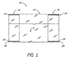
- Figure 1 is a top plan view of a retention member having pockets
- Figure 2 is a bottom plan view of a tray member in an unfolded and unassembled state, the tray member having foldable portions disposed around a periphery of a central portion;
- Figure 3 is a bottom plan view the tray member of Figure 2 in a folded state
- Figure 4 is an enlarged elevational view of a folding portion of the tray member of Figure 2 with a foldable portion inserted into one of the pockets of the retention member of Figure 1;
- Figure 5 is an elevational view of the folding portion of Figure 4 in the folded state
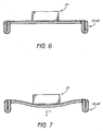
- Figure 6 is a partial sectional view of the tray member and retention member connected together and supporting an article to packaged thereon;
- Figure 7 is an elevational and partial sectional view of the arrangement in Figure 6 showing a deflected state of the assembly and showing the flexation of the assembly when the article to be packaged is subjected to an acceleration;
- Figure 8 is a bottom plan view of a modification of the tray member illustrated in Figure 2, in an unassembled and unfolded state;
- Figure 9 is an elevational and partial sectional view of the tray member of Figure 8, connected with a retention member and supporting an article to be packaged;
- Figure 10 is an elevational and partial sectional view of the arrangement shown in Figure 9, with the tray member and retention member in a deflected state;
- Figure 11 is a bottom plan view of a further modification of the tray member of Figure 2 illustrated in an unassembled and unfolded state;
- Figure 12 is an elevational and partial sectional view of the tray member of Figure 11 connected to a retention member and supporting an article to be packaged;
- Figure 13 is an elevational and partial sectional view of the arrangement shown in Figure 12 and showing a deflected state of the arrangement;
- Figure 14 is a bottom plan view of yet another modification of the tray member illustrated in Figure 2 including a removable wall member and foldable locking member illustrated in an unassembled and unfolded state;
- Figure 15 is a bottom plan view of the tray member of Figure 14 in a folded state
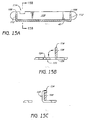
- Figure 15A is a sectional and partial elevational view of the tray of Figure 15 with the wall member removed and inserted into slots in the side walls of the tray member;
- Figure 15B is a sectional view taken along line 15B-15B of Figure 15A;
- Figure 15C is another sectional view showing the folded position of locking member locking the wall member of Figure 15A in place;
- Figure 15D is a bottom plan view of the arrangement of Figure 15A;
- Figure 15E a bottom plan view of the arrangement of Figure 15C;
- Figure 16 is a bottom plan view of a modification of the tray member of Figure 14 in an unassembled and unfolded state
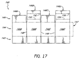
- Figure 17 is a plan view of a box member illustrated in an unassembled and unfolded state
- Figure 18 is a top, front, and left-side perspective view of the box member of Figure 17 in an assembled state with the top portion open;
- Figure 19 is a sectional view of the box of Figure 18 in a partially closed state with a retention member being engaged with two of the top flaps of the box;
- Figure 20 is a sectional view of the box of Figure 18 closed and supporting an article within the box.
- the packaging system includes an improved structure which provides new alternatives to known suspension packaging devices.
- orientation such as “upper,” “lower,” “longitudinal,” “horizontal,” “vertical,” “lateral,” “midpoint,” and “end” are used here to simplify the description in the context of the illustrated embodiment. Because other orientations are possible, however, the present inventions should not be limited to the illustrated orientation. Those skilled in the art will appreciate that other orientations of the various components described above are possible.
- FIG. 1 illustrates a retention member 10.
- the retention member 10 is preferably formed of a resilient body 12.
- the body 12 is identified as having a midpoint M positioned in the vicinity of the middle of the resilient body.
- the resilient body 12 also includes pockets 14, 16 at opposite ends thereof.
- the retention member 10 is formed of a single piece of resilient material, and is sized to cooperate with another member having foldable portions, described in greater detail below.
- the pockets 14, 16 are formed of folds 18, 20 formed in the resilient body 12 which have been attached (e.g., heat sealed) along lateral opposite edges thereof.
- the heat sealing process forms the heat sealing lines 22, 24, 26, 28.
- the heat sealing lines 22, 24, 26, 28 can be continuous or formed of a plurality of heat-sealed points.
- heat sealing is particularly advantageous as it does not require expensive adhesives and the time consuming steps required for using it adhesives.
- the retention member 10 has a length L 1 that is sized depending on the other devices with which the retention member 10 is to cooperate.
- the length L 1 can be sized such that when the retention member is in its final state, e.g., engaged with folding members of another device, it generates the desired tension for the corresponding application.
- the length L 1 will be smaller where a higher tension is desired and will be larger where a lower tension is desired.
- the length L 1 might be different for different sized articles that are to be packaged.
- One of ordinary skill in the art can determine the length L 1 for the corresponding application.
- the retention member 10 can be formed of any resilient material.
- the retention member 10 can be made of applicable polyethylene film.
- virtually polymer, elastomer, or plastic film can be used to form the retention member 10.
- the density of the film can be varied to provide the desired retention characteristics such as overall strength, resiliency, and vibrational response.
- the density of the retention member 10 is determined such that the retention member 10 is substantially resilient when used to package a particular article.
- a tray member 40 is configured to be folded into a shape generally corresponding to a tray.
- this type of device is long been known in the art.
- the tray member 40 can be constructed from various materials, including but without limitation, paper, cardboard, corrugated cardboard, plastic, and/or other appropriate materials.
- the chosen material for constructing the tray member 40 can be any substantially rigid but foldable material. It will be appreciated that, although denominated as rigid, the chosen material would preferably have a certain amount of flexibility in the cases of extreme physical impact.
- the material used to form the tray member 40 is a single wall corrugated C-flute cardboard.
- FIG. 2 illustrates a bottom plan view of the tray member 40.
- the tray member 40 includes a central base member 42 and a plurality of foldable portions 44, 46, 48, 50. When assembled, the foldable portions 44, 46, 48, 50 are folded to define peripheral walls extending around the base member 42 and extending generally perpendicular to the base portion 42.
- Each of the foldable portions 44, 46, 48, 50 include a proximal portion 52 that is disposed proximal to the base portion 42 and a distal portion 54 that is disposed distally from the base portion 42.
- the proximal portions 52 generally define a connection between the foldable portions 44, 46, 48, 50 and the base portion 42.
- Each of the proximal portions 52 include a fold line 56.
- the fold lines 56 can be formed as perforations in the tray member 40, i.e., broken cut lines passing partially or completely through the material forming the tray member 40. In the alternative, or in addition, the fold lines 56 can be crushed portions of the material forming the tray member 40. Of course, depending on the material used to construct the tray member 40, the fold lines 56 can be formed as mechanical hinges, thinned portions or any other appropriate mechanical connection which would allow various portions of the tray member 40 to be folded or rotated with respect to each other.
- the foldable portions 44, 46, 48, 50 also include medial fold lines 58.
- the medial fold lines 58 allow each of the foldable portions 44, 46, 48, 50 to be folded.
- each of the foldable portions 44, 46, 48, 50 can be folded in half to define a double-walled portion around a periphery of the base member 42.
- the distal portions 54 also include at least one protrusion 60.
- each of the distal portions 54 include two protrusions 60.
- the number of protrusions 60 on the distal portions 54 can be varied.
- the protrusions 60 on the distal portions 54 are configured to engage with apertures 62 disposed in the vicinity of the proximal portions 52.
- the protrusion 60 can be inserted into the apertures 62, thereby securing the foldable portions 44, 46, 48, 50 into place. This technique is well known in the art.
- the illustrated tray member 40 also includes corner members 64 disposed on opposite ends of the foldable portions 46 and 48. Each of the corner members 64 are connected to the respective foldable portion 44, 48 by a corner fold line 66.
- the corner members 64 can first be folded upwardly, as viewed in Figure 2, about the fold lines 66. Then, the foldable portions 44, 48 can be folded inwardly toward the base portion 44 about the fold lines 56. Once the foldable portions 44, 48 are folded into a state in which they extend generally perpendicular to the base portion 42, the corner member 64 will be generally aligned with the fold lines 56 of the foldable portions 46, 50.
- the foldable portions 44, 48 can be folded about the medial fold lines 58 until the protrusions 60 engage with the apertures 62.
- the foldable portions 44, 48 can be sized such that as the foldable portions 44, 48 are folded about the medial fold line 58, the protrusions 60 snap into the apertures 62, thereby locking the foldable portions 44, 48 into that folded state.
- the foldable portions 46, 50 can be folded about their medial fold lines 58 in a similar manner.
- the corner members 64 are sandwiched within the respective foldable portions 46, 50, thereby locking the foldable portions 44, 46, 48, 50 together. This provides an enhanced structural rigidity of the tray member 40.
- Figure 3 is a bottom plan view of the tray member 40 in the folded state.
- the pockets 14, 16 of the retention member 10 can be connected to the foldable portions 44, 48 or the foldable portions 46, 50.
- foldable portion 50 is illustrated as being received with pocket 14 of the retention member 10. As such, the protrusion 60 is disposed within the pocket 14. Additionally, although not illustrated, in this method of assembling the tray member 40, the foldable portion 46 is received within the pocket 16 of the retention member 10.
- the foldable portion 50 is folded about the fold line 56 and the fold line 58 until the protrusion 60 is engaged with the apertures 62. Additionally, the foldable portion 46 is also folded in a similar manner. When folded as such, the retention member 10 is stretched by the foldable portions 50, 46. The amount of tension generated by the folding of the foldable portions 46, 50 can be adjusted by adjusting the length L 1 of the retention member 10 ( Figure 1).
- the assembled retention member 10 and tray member 40 are illustrated therein as supporting an article to be packaged 70.
- the retention member, tray member 40, and the article 70 can be packaged together within a box (not shown) such that the retention member 10 and tray member 40 can absorb shocks imparted into the article 70.
- the retention member 10 and tray member 40 can deflect together when a load I is applied to the article 70. As such, the retention member 10 and tray member 40 absorb the shock and thus prevent the article 70 from being damaged.
- a portion of the base member 42 can be removed. In such an embodiment, either the retention member 10 or the base member 42 can primarily support the article 70. However, other modifications of the base member 42 can also be made.
- tray member 40' a modification of the tray member 40 is illustrated therein and identified generally by the reference numeral 40'.
- the tray member 40' illustrated in Figures 8-10 can be constructed substantially identically to the tray member 40 illustrated in Figures 2-7, except as noted as below.
- the tray member 40' shown in Figures 8-9 includes the same reference numerals as the tray member 40 shown in Figures 2-7, however, with a "'" added.
- the above description applies equally to the common elements unless otherwise indicated. Therefore, the description of those components will not be repeated.
- the tray member 40' can include one or a plurality of at least one of cut lines and fold lines therein.
- the tray member 40' includes a plurality of cut lines 82 disposed in a central area of the base portion 42.
- the cut lines 82 can be formed by completely or nearly completely cutting through the material forming the base member 42.
- the cut lines 82 are generally arranged in the shape of a "T".
- the base member 42 includes a plurality of score lines 84.
- the score lines extend generally from the corners of the base member 42 toward the cut lines 82.
- the score lines 84 can be formed in the same manner as any of the above noted fold lines 52, 58, 66.
- the score lines 84 include discontinuous cuts extending through the material forming the base member 42.
- the cut lines 82 and score lines 84 can provide additional flexibility to the base member 42, thereby providing additional shock absorption.
- the cut lines 82 can allow a portion of the base member 42 to separate ( Figure 10) and thereby further absorb energy from an impact or force I applied to the article 70.
- the score lines 84 can further allow the base member 42 to separate or flex thereby further absorbing energy from the force I applied to the article 70.
- tray member 40 With reference to Figures 11-13, a further modification the tray member 40 is illustrated therein and identified generally by the reference numeral 40".
- the tray member 40" shown in Figures 11-13 is constructed substantially identically to the tray members 40, 40', except as noted below.
- the tray member 40" shown in Figures 11-13 includes the same reference numerals as the tray members 40, 40', except that a "double prime" has been added.
- the above description applies equally to the common elements unless otherwise indicated. Therefore, a description of the common elements will not be repeated.
- the tray member 40" can also include additional score lines 90.
- the additional score lines 90 extend generally parallel to the fold lines 56.
- the score lines 90 can be arranged generally concentrically around the central area of the base member 42.
- the score lines 90 can be formed in any of the above-noted methods for forming fold lines or score lines, or other methods.
- the score lines 90 further aid in absorbing the energy created by the force I by allowing the base member 42 to further bend.
- the arrangement, size, and number of cut lines 82 and score lines 84, 90 can be adjusted to provide the desired energy absorption characteristic of the retention member 10 and tray member 40".
- Figure 14 illustrates yet another modification of the tray member 40 illustrated in Figure 2 which is identified generally by the reference numeral 100.
- Certain components of the tray member 100 can be constructed identically or generally the same as corresponding components of the tray members 40, 40', 40". Those components are identified with the same reference numeral used with regard to the corresponding components of the tray members 40, 40', 40". Thus, a further description of those components will not be repeated. The above description applies equally to the common elements unless otherwise indicated.
- the tray member 100 includes foldable portions 46, 50 arranged opposite each other. Additionally, the tray member 100 includes foldable portions 102, 104 that are also disposed opposite each other. The foldable portions 102, 104 do not include the medial fold line 58 that are included with the foldable portions 46, 50. Rather, the foldable portions 102, 104 are configured to form only a single wall when in the assembled state. Thus, the distal portions 54 of the foldable portions 102, 104 do not include the protrusions 60. Additionally, the proximal portions 52 of the foldable portions 102, 104 do not include apertures 62.
- the foldable portions 102, 104 can include corner members 64 attached to the foldable portions 102, 104 at fold lines 66.
- the foldable portions 102, 104 also include retaining grooves 106 configured to cooperate with an optional wall member 108.
- the optional wall member 108 can be formed by providing one or a plurality of cut or score lines 110 in the base member 42.
- the cut or score lines 110 extend around a periphery of the wall member 108.
- the cut or score lines 110 can also define one or a plurality of anchor grooves 112.
- the anchor grooves 112 are sized to as to be alignable with the alignment grooves 106.
- the cut or score lines 110 can also define a locking notch 114.
- the locking notch 114 can be used in conjunction with other devices or portions of the tray member 100, described in greater detail below.
- the tray member 100 can also include a lock panel 120.
- the lock panel 120 can be configured to lock the wall member 108 relative to the base portion 42.
- the lock panel 120 is defined by cut or score lines 122.
- the cut or score lines 122 can be arranged to define a locking tab 124 configured to engage the notch 114.
- the lock panel 120 can include a fold line 126 configured to allow the panel 120 to be rotated relative to the base member 42.
- Figure 15 illustrates the tray member 100 in an assembled state in which the foldable portions 46, 50, 102, 104 are folded into place so as to define a wall extending peripherally around the base portion 42.
- the wall portion 108 Prior to or subsequent to assembling the tray member 100 as such, the wall portion 108 can be removed from the base portion 42.
- One of ordinary skill in the art can configure the cut or score lines 110 to allow the wall portion 108 to be removed or optionally left in place during use.
- the wall portion 108 can be removed from the base portion 42 and engaged with the foldable portions 102, 104.
- the anchor grooves 112 can be aligned with the alignment notches 106.
- the wall member 108 With the alignment grooves 106 and anchor grooves 112 nested with each other, as illustrated in Figure 15A, the wall member 108 can be held in place so as to define a partition between areas on the bottom of the tray member 100.
- the wall member 108 divides the bottom of the tray member into areas 130 and 132. These divided areas 130, 132 can be used separate or keep separate items associated with an item to be packaged.
- the anchor notch 114 faces upwardly.
- the anchor panel 120 can be folded about the fold line 126 such that the panel 120 lies generally parallel to the wall 108, as illustrated in Figure 15C. Additionally, the lock tab 124 can be further folded so as to engage with the lock groove 114.
- the locking tab 124 can form an enlarged head portion. As such, when the locking tab 124 is fit into the lock groove 114, the enlarged head portion of the tab 124 aids in retaining the tab 124 in engagement with the groove 114.
- Figure 15E illustrates a bottom plan view of the tray member 100 in the arrangement illustrated in Figure 15C.
- the wall member 108 is locked in place by the locking panel 120 with the lock tab 124 engaged with the lock groove 114.
- the lock panel 120 aids in helping keep the wall 108 from collapsing during use.
- the base portion 42 is provided with enhanced flexibility.
- the base portion 42 can flex and thus absorb additional energy created by a force I acting on the article 70, similarly to the behavior of the tray member 40' illustrated in Figures 9 and 10.
- Figure 16 illustrates a modification of the tray member 100, identified generally by the reference numeral 100'.
- Components of the tray member 100' that are the same or similar to corresponding components of the tray member 100 are identified with the same reference numerals. The above description applies equally to the common elements unless otherwise indicated. Therefore, a further description of those elements is not repeated below.
- the tray member 100' can include a plurality of cut lines 140. Additionally, or in the alternative, the tray member 100' can include a plurality of score or fold lines 142. The inclusion of cut lines 140 and/or score or cut lines 142 allows the tray member 100' to behave in a manner described above with reference to the tray member 40" and with reference to Figures 12 and 13.
- the foldable portions 46, 50 can be inserted into the pockets of a resilient member, such as the resilient member 10 illustrated in Figure 1. Thereafter, the foldable portions 46, 50 can be folded so as to engage the protrusions 60 with the apertures 62.
- the tray members 100, 100' can perform in accordance with the description set forth above with respect to the suspension assemblies comprising retention member 10 and one of the tray members 40, 40', 40".
- Figure 17 illustrates a container member 140 in an unassembled and unfolded state.
- the container member 140 can be formed from a single or multiple pieces of generally rigid material.
- the rigid material can be the same or similar to the materials described above with reference to a tray member 40.
- the container member 140 can be formed from a corrugated cardboard material. However, other materials can also be used.
- the container member 140 includes a plurality of bottom flaps 142, a plurality of wall panels 144, and a plurality of top flaps 146. Additionally, the container member 140 can include a wall connector member 147.
- the wall panels 144 are identified as wall panel 144A, 144B, 144C, 144D.
- the wall panels 144A, 144B, 144C, 144D can be connected along fold lines 148.
- the construction of the bottom flaps 142, wall panels 144, and connector 146 can be in accordance with the long and well known technique for forming a cardboard box out of a single piece of cardboard.
- the plurality of wall panels 144 can be folded along the fold lines 146 and the connector 147 can be attached to the wall panel 144A, so as to form a box.
- the bottom flaps 142 can be folded and secured in a known manner to form a bottom of a box. Assembled as such, the container member 140 takes the shape illustrated in Figure 18.
- the plurality of top flaps 146 are identified as 146A, 146B, 146C, 146D.
- the top flaps 146B, 146D which are disposed opposite to each other when the container member 140 is folded in the state illustrated in Figure 18A, include proximal and distal fold lines.
- the top flap 146B includes a proximal fold line 150 and a distal fold line 152.
- the top flap 146D includes a proximal fold line 154 and a distal fold line 156.
- the container member 140 can be used in conjunction with a retainer member such as the retainer member 10 illustrated in Figure 1.
- a retainer member such as the retainer member 10 illustrated in Figure 1.
- FIG 19. by folding the top flaps 146B, 146D about the fold lines 152, 156, respectively, the distal ends of the flaps 146B, 146D can be inserted into the pockets 14, 16 of the retention member 10. This arrangement is shown in Figure 19.
- an article to be packaged 70 can be disposed within the container member 140 prior to the connection of the retention member 10 to the top flaps 146.
- the top flaps 146B, 146D can be further rotated inwardly, into the interior of the box member 140, thereby tightening the retention member 10.
- the article to be packaged 70 can be supported above the bottom of the box member 140 with any desired device.
- tray members 40, 40', 40", 100, 100' and a retention member, such as the retention member 10 are used to support the article 70 in a position spaced from the bottom of the container member 140.
- Figure 20 illustrates a tray member identified generally by the T engaged with a retention member identified generally by the reference numeral R supporting the article 70 above a bottom of the container member 140.
- the tray member T can be any one of the tray members 40, 40', 40", 100, 100' described above.
- the retention member R can be any resilient member, including, for example, but without limitation, the retention member 10 illustrated in Figure 1.
- the retention member 10 is engaged with the top flaps 146B, 146D and the top flaps 146B, 146D are folded inwardly so as to tighten the retention member 10 across the top of the article 70. Additionally, the corners of the top flaps 146B, 146D created by the folding of the top flaps about the fold lines 152, 156 can be tucked between the upper periphery of the tray member T and the wall panels 144B, 144D, respectively. As such, the top flaps 146B, 146D are held in place and thus, generate tension in the retention member 10.
- top flaps 146A, 146C can be folded over the top flaps 146B, 146D to thereby further retain the top flaps 146B, 146D in the position shown in Figure 20.
- the retention members 10, R can be used to completely suspend the article 70 in an interior of the box member 140 in a position spaced from all of the walls and the top and bottom of the box member 140.
- the additional material of the base member 42 can be used to further cushion or absorb energy generated by forces acting on the article 70, in accordance with the description set forth above with respect to Figures 6, 7, 9, 10, 12, and 13.
Landscapes
- Engineering & Computer Science (AREA)
- Mechanical Engineering (AREA)
- Buffer Packaging (AREA)
- Cartons (AREA)
- Supplying Of Containers To The Packaging Station (AREA)
- Container Filling Or Packaging Operations (AREA)
- Time-Division Multiplex Systems (AREA)
Applications Claiming Priority (1)
| Application Number | Priority Date | Filing Date | Title |
|---|---|---|---|
| US10/990,095 US20060102515A1 (en) | 2004-11-15 | 2004-11-15 | Suspension packaging system |
Publications (3)
| Publication Number | Publication Date |
|---|---|
| EP1657166A2 true EP1657166A2 (fr) | 2006-05-17 |
| EP1657166A3 EP1657166A3 (fr) | 2006-07-19 |
| EP1657166B1 EP1657166B1 (fr) | 2011-12-28 |
Family
ID=35734062
Family Applications (1)
| Application Number | Title | Priority Date | Filing Date |
|---|---|---|---|
| EP05013333A Expired - Lifetime EP1657166B1 (fr) | 2004-11-15 | 2005-06-21 | Système d'emballage en suspension |
Country Status (4)
| Country | Link |
|---|---|
| US (2) | US20060102515A1 (fr) |
| EP (1) | EP1657166B1 (fr) |
| CN (1) | CN1781821B (fr) |
| AT (1) | ATE539001T1 (fr) |
Cited By (4)
| Publication number | Priority date | Publication date | Assignee | Title |
|---|---|---|---|---|
| WO2015086515A1 (fr) * | 2013-12-13 | 2015-06-18 | Tetra Laval Holdings & Finance S.A. | Emballage secondaire et son procédé de mise en oeuvre |
| US10315829B2 (en) | 2012-09-14 | 2019-06-11 | Clearpak, Llc | Multi-layered suspension package assembly |
| US10392156B2 (en) | 2017-04-10 | 2019-08-27 | John McDonald | Return shipping system |
| US11124348B2 (en) | 2014-03-21 | 2021-09-21 | John McDonald | Heat sealed packaging assemblies and methods of producing and using the same |
Families Citing this family (42)
| Publication number | Priority date | Publication date | Assignee | Title |
|---|---|---|---|---|
| US6675973B1 (en) | 2000-07-31 | 2004-01-13 | Mcdonald John | Suspension packaging assembly |
| US20060102515A1 (en) * | 2004-11-15 | 2006-05-18 | Mcdonald John | Suspension packaging system |
| US7296681B2 (en) * | 2004-12-23 | 2007-11-20 | Mcdonald John | Suspension packaging system |
| US7753209B2 (en) * | 2006-04-27 | 2010-07-13 | Mcdonald John | Suspension package assembly |
| JP4210693B2 (ja) * | 2006-08-29 | 2009-01-21 | 日信工業株式会社 | トレイおよびこれを用いたコンテナ |
| US8235216B2 (en) * | 2006-12-05 | 2012-08-07 | Clearpak, Llc | Suspension packaging assembly |
| US20080223750A1 (en) * | 2007-03-16 | 2008-09-18 | Mcdonald John | Suspension package assembly |
| JP5178234B2 (ja) * | 2008-02-22 | 2013-04-10 | ヤマト包装技術研究所株式会社 | 薄型物品の輸送用梱包具 |
| US8627958B2 (en) | 2008-07-02 | 2014-01-14 | Clearpak, Llc | Suspension packaging system |
| CA2739032A1 (fr) * | 2008-09-30 | 2010-04-08 | David Goodrich | Systeme d'emballage a retention et suspension |
| US20110108450A1 (en) * | 2008-09-30 | 2011-05-12 | David Goodrich | Suspension Packaging System |
| US20110024324A1 (en) * | 2009-07-28 | 2011-02-03 | Columbia Corrugated Box | Suspension / retention packaging |
| WO2011021858A2 (fr) * | 2009-08-19 | 2011-02-24 | (주)제일산업포장 | Boîte d'emballage |
| US8714357B2 (en) * | 2010-04-06 | 2014-05-06 | Sealed Air Corporation (Us) | Packaging system |
| US8752707B2 (en) | 2010-08-19 | 2014-06-17 | Clearpak, Llc | Foldable packaging member and packaging system using foldable packaging members |
| US8727123B1 (en) | 2011-03-11 | 2014-05-20 | Larry Roberts | Suspension packaging assembly |
| US9150343B2 (en) | 2011-03-11 | 2015-10-06 | Larry Roberts | Suspension packaging assembly |
| US20130048533A1 (en) * | 2011-08-30 | 2013-02-28 | John McDonald | Packaging systems and kits |
| US9309024B2 (en) | 2012-03-09 | 2016-04-12 | Sealed Air Corporation (Us) | Packaging assembly |
| USD706136S1 (en) | 2012-03-12 | 2014-06-03 | Larry Roberts | Suspension packaging |
| US9067722B2 (en) | 2012-09-14 | 2015-06-30 | Clearpak, Llc | Multi-layered suspension package assembly |
| FR3001955B1 (fr) * | 2013-02-12 | 2015-10-30 | B & Equipment | Cale pour immobiliser des objets dans une boite a section carree ou rectangulaire. |
| US9573722B1 (en) * | 2013-05-28 | 2017-02-21 | Green Bay Packaging, Inc. | Carton with corner crumple zones |
| US9199761B2 (en) | 2013-10-28 | 2015-12-01 | John McDonald | Compressible packaging assembly |
| US9463915B2 (en) | 2013-10-28 | 2016-10-11 | John McDonald | Compressible packaging assembly |
| WO2015152950A1 (fr) * | 2014-03-31 | 2015-10-08 | Larry Roberts | Ensemble d'emballage pour suspension |
| JP6188618B2 (ja) | 2014-03-31 | 2017-08-30 | 三菱電機株式会社 | 空気調和機の梱包装置及び空気調和機 |
| US9592647B2 (en) * | 2014-08-01 | 2017-03-14 | Dell Products L.P. | Modular corrugated container having integrated cushioning |
| WO2016040787A1 (fr) * | 2014-09-11 | 2016-03-17 | Sealed Air Corporation (Us) | Ensemble d'emballage |
| US10252135B1 (en) | 2014-10-27 | 2019-04-09 | Larry Roberts | Exercise assembly |
| US11938372B1 (en) | 2014-10-27 | 2024-03-26 | Larry Roberts | Exercise assembly |
| WO2016069893A1 (fr) | 2014-10-31 | 2016-05-06 | Sealed Air Corporation (Us) | Cadre de retenue pour un ensemble d'emballage |
| US20160122062A1 (en) * | 2014-11-03 | 2016-05-05 | Jack Vincent Smith | String Box and Method of Use Thereof |
| US20160101923A1 (en) * | 2015-10-12 | 2016-04-14 | Thatbox Design, Llc | Suspension pack box designs, blanks and methods |
| KR102622713B1 (ko) * | 2016-06-09 | 2024-01-09 | 삼성전자주식회사 | 패킹부재 및 이를 구비하는 조리기기 |
| JP6601355B2 (ja) * | 2016-09-21 | 2019-11-06 | 京セラドキュメントソリューションズ株式会社 | 緩衝材、及び梱包材 |
| JP6874263B2 (ja) * | 2017-07-20 | 2021-05-19 | ザ・パック株式会社 | 緩衝材及び緩衝材を用いた梱包方法 |
| US10947007B2 (en) * | 2017-07-21 | 2021-03-16 | Sealed Air Corporation (Us) | Retention packaging assembly |
| US10450122B2 (en) | 2018-02-13 | 2019-10-22 | Reflex Packaging Inc. | Cushioning pack for articles of different size |
| US11672360B2 (en) * | 2019-02-27 | 2023-06-13 | Inducomp Corporation | Ball display case |
| CN111572888B (zh) * | 2019-09-30 | 2021-08-17 | 浙江大华技术股份有限公司 | 薄膜包装内衬的包装方法 |
| US11530084B1 (en) * | 2020-01-13 | 2022-12-20 | Packaging Corporation Of America | Product insert and shipper |
Family Cites Families (92)
| Publication number | Priority date | Publication date | Assignee | Title |
|---|---|---|---|---|
| US1821692A (en) | 1930-10-02 | 1931-09-01 | George A Copeland | Packing case |
| US2161128A (en) * | 1937-11-11 | 1939-06-06 | Cons Carton Inc | Carton structure |
| US2948455A (en) | 1951-06-18 | 1960-08-09 | William P Frankenstein | Carton |
| US2723796A (en) * | 1952-11-08 | 1955-11-15 | George V Malmgren | Partition tray |
| US2797855A (en) * | 1953-11-20 | 1957-07-02 | Cel Corp Di | Package trays |
| US2956672A (en) * | 1958-12-19 | 1960-10-18 | Grace W R & Co | Packaging |
| US3047137A (en) * | 1959-11-02 | 1962-07-31 | Bemis Bro Bag Co | Package construction |
| US3285493A (en) * | 1964-06-10 | 1966-11-15 | Brown Co | Compartmented tray structure |
| US3345643A (en) | 1965-03-29 | 1967-10-10 | Mary A L Bradley | Disposable dress shield |
| US3326410A (en) * | 1965-06-07 | 1967-06-20 | Shell Oil Co | Stackable, nestable, interlocking container |
| US3853220A (en) * | 1972-02-22 | 1974-12-10 | H Luray | Hammock package |
| US3917108A (en) * | 1972-02-22 | 1975-11-04 | Dare Plastics Inc | Plastic tray and method of making same |
| JPS5222543Y2 (fr) * | 1972-09-06 | 1977-05-24 | ||
| US4077518A (en) | 1977-04-12 | 1978-03-07 | The United States Of America As Represented By The Secretary Of The Navy | Sensor transport system |
| US4155453A (en) * | 1978-02-27 | 1979-05-22 | Ono Dan D | Inflatable grip container |
| SU827346A1 (ru) | 1979-01-09 | 1981-05-07 | Предприятие П/Я М-5907 | Упаковка дл хрупких изделий |
| US4606460A (en) | 1982-02-22 | 1986-08-19 | Luray Howard L | Protective packages |
| IT1153034B (it) * | 1982-11-15 | 1987-01-14 | Grace W R & Co | Procedimento ed apparecchiatura per il confezionamento sottovuoto e reativa confezione |
| US4801774A (en) * | 1987-11-24 | 1989-01-31 | Container Corporation Of America | Center-supported microwave tray |
| US5071009A (en) * | 1988-02-29 | 1991-12-10 | Ridgeway Louis H | Retaining and shock-absorbing packing insert |
| US4852743A (en) * | 1988-02-29 | 1989-08-01 | Ridgeway Louis H | Membrane packing |
| US4923065A (en) * | 1988-02-29 | 1990-05-08 | Ridgeway Louis H | Membrane packing and retainer |
| US4830272A (en) * | 1988-05-31 | 1989-05-16 | Wear Philip A | Display tray structure |
| US5080497A (en) | 1990-06-05 | 1992-01-14 | Paramount Packaging Corporation | Bag with a square end and a handle |
| US5226542A (en) * | 1990-06-18 | 1993-07-13 | Ade, Inc. | Suspension package |
| US5056665A (en) | 1990-06-18 | 1991-10-15 | Ade, Inc. | Suspension package |
| US5046659A (en) | 1990-11-13 | 1991-09-10 | Mobil Oil Corporation | Latching structure for food container |
| US5223121A (en) * | 1991-05-02 | 1993-06-29 | Dickie Robert G | Protective carton with progressive product clamping |
| US5183159A (en) | 1991-07-26 | 1993-02-02 | United Foam Plastics | Suspension cushioning package |
| US5218510A (en) * | 1991-09-23 | 1993-06-08 | Bradford Company | Suspension packaging for static-sensitive products |
| JPH0723164B2 (ja) * | 1991-12-19 | 1995-03-15 | 中央紙器工業株式会社 | 段ボール製パッキン |
| US5211290A (en) | 1992-08-10 | 1993-05-18 | Ade, Inc. | Suspension package and system |
| DE9307058U1 (de) | 1992-12-10 | 1993-07-15 | Philips Electronics N.V., Eindhoven | Verpackte elektrische Lampe und Verpackungszuschnitt |
| US5251760A (en) | 1993-02-16 | 1993-10-12 | Squire Corrugated Container Corp. | Shipping package |
| US5323896A (en) * | 1993-06-24 | 1994-06-28 | Jones W Charles | Article packaging kit, system and method |
| US5388701A (en) * | 1993-11-22 | 1995-02-14 | Sealed Air Corporation | Suspension packaging |
| US5492223A (en) * | 1994-02-04 | 1996-02-20 | Motorola, Inc. | Interlocking and invertible semiconductor device tray and test contactor mating thereto |
| US5405000A (en) * | 1994-02-28 | 1995-04-11 | Hagedon; Bryan D. | Protective suspension package |
| US5372257A (en) * | 1994-04-20 | 1994-12-13 | Ipl Inc. | Stackable load bearing tray |
| US5579917A (en) | 1995-05-16 | 1996-12-03 | Ade, Inc. | Suspension package |
| US5641068A (en) * | 1995-06-15 | 1997-06-24 | Hewlett-Packard Company | Adjustable and reusable protective packaging system |
| US6010003A (en) | 1995-08-28 | 2000-01-04 | Kpc Master's Craft International, Inc. | Shrink package |
| US5678695A (en) * | 1995-10-11 | 1997-10-21 | Sealed Air Corporation | Packaging structure |
| US6148590A (en) * | 1995-10-11 | 2000-11-21 | Sealed Air Corporation | Packaging structure |
| US5797493A (en) * | 1995-10-27 | 1998-08-25 | Watson; Thomas J. | Plumbing fittings and method of packaging therefor |
| US5694744A (en) * | 1996-02-29 | 1997-12-09 | Jones; William Charles | Article packaging kit, and method |
| US5676245A (en) * | 1996-04-02 | 1997-10-14 | Jones; William Charles | Article packaging kit, system and method |
| US5769235A (en) | 1996-06-19 | 1998-06-23 | Ade, Inc. | Packaging device and method for assembling same |
| US5669506A (en) * | 1996-07-31 | 1997-09-23 | Ade, Inc. | Suspension package |
| US5738218A (en) | 1996-10-30 | 1998-04-14 | Gonzales; Juanita A. | Foldable protective packaging |
| US5788081A (en) * | 1996-11-20 | 1998-08-04 | The Mead Corporation | Compartmented tray |
| US5823348A (en) | 1997-05-20 | 1998-10-20 | Ade, Inc. | Suspension package |
| US5823352A (en) * | 1997-06-03 | 1998-10-20 | Summit Container Corporation | Container with shock-absorbing insert |
| US5894932A (en) * | 1997-06-12 | 1999-04-20 | Ade, Inc. | Suspension package |
| DE19758661C2 (de) * | 1997-06-17 | 2002-07-25 | Aesculap Ag & Co Kg | Verpackungseinheit für steril zu verpackende Gegenstände |
| US5803267A (en) | 1997-07-29 | 1998-09-08 | Chicony Electronics Co., Ltd. | Structural improvement on keyboard packaging box |
| US5954203A (en) * | 1997-12-24 | 1999-09-21 | Allegiance Corporation | Packaging container |
| US5975307A (en) | 1998-03-06 | 1999-11-02 | Ade, Inc. | Suspension package |
| CN1267267A (zh) | 1998-04-14 | 2000-09-20 | 德克萨斯黎伯迪纸板箱公司 | 用于压缩机和其它货物的容器 |
| WO1999064317A1 (fr) | 1998-06-10 | 1999-12-16 | Motion Design, Inc. | Boite comportant un element elastique interieur |
| US5988387A (en) | 1998-07-01 | 1999-11-23 | Ade, Inc. | Suspension package |
| US5893462A (en) | 1998-07-01 | 1999-04-13 | Sealed Air Corporation | Retention package |
| US5967327A (en) | 1998-10-02 | 1999-10-19 | Emerging Technologies Trust | Article suspension package, system and method |
| DE29921203U1 (de) | 1999-03-08 | 2000-02-24 | Schilling, Frank, 25486 Alveslohe | Verpackungselement zur gepolsterten, versandgeeigneten Aufnahme von Verpackungsgut |
| US6073761A (en) | 1999-05-11 | 2000-06-13 | Emerging Technologies Trust | Recyclable article packaging system |
| DE19938249C2 (de) * | 1999-08-12 | 2002-03-07 | Stabilus Gmbh | Axial beweglicher Schaltring innerhalb einer Nut |
| US6158589A (en) * | 1999-09-23 | 2000-12-12 | Motion Design, Inc. | Boxes with internal resilient elements |
| US6311843B1 (en) | 1999-10-01 | 2001-11-06 | Motion Design, Inc. | Packaging boxes and components with internal resilient elements |
| US6302274B1 (en) * | 1999-12-01 | 2001-10-16 | Sealed Air Corporation (Us) | Suspension and retention packaging structures and methods for forming same |
| US6467624B1 (en) | 2000-01-18 | 2002-10-22 | Ade, Inc. | Suspension package |
| US6119863A (en) | 2000-01-18 | 2000-09-19 | Ade, Inc. | Suspension package |
| US6223901B1 (en) * | 2000-02-08 | 2001-05-01 | Ade, Inc. | Suspension package |
| WO2001081204A1 (fr) | 2000-04-24 | 2001-11-01 | Motion Design, Inc. | Articles d'emballage avec elements de maintien pouvant etre tendus |
| US6675973B1 (en) | 2000-07-31 | 2004-01-13 | Mcdonald John | Suspension packaging assembly |
| DE20017182U1 (de) | 2000-10-06 | 2002-02-14 | Bischof und Klein GmbH & Co., 49525 Lengerich | Seitenfaltenbeutel aus flexiblen schweißbarem Material |
| DE10105487A1 (de) * | 2001-02-07 | 2002-08-08 | Sca Packaging Deutschland Ag & | Faltkiste mit Halteeinrichtung |
| US6712212B2 (en) | 2001-02-16 | 2004-03-30 | Meadwestvaco Packaging Systems, Llc | Carton and a cushion member for placement into a carton |
| JP2003292048A (ja) | 2002-03-28 | 2003-10-15 | Seiko Epson Corp | 梱包物、梱包方法及び仕切り部材 |
| US6976586B2 (en) | 2002-05-10 | 2005-12-20 | Asm America, Inc. | Delicate product packaging system |
| US6920981B2 (en) | 2003-01-03 | 2005-07-26 | Ade, Inc. | Suspension packages and systems, cushioning panels, and methods of using same |
| US7086534B2 (en) | 2003-01-21 | 2006-08-08 | Sealed Air Verpackungen Gmbh | Suspension and retention packaging structures and methods for forming same |
| US6899229B2 (en) | 2003-07-18 | 2005-05-31 | Sealed Air Corporation (Us) | Packaging container with integrated sheet for retention of packaged article |
| US7000774B2 (en) | 2003-09-02 | 2006-02-21 | Dominic Bryant | Universal packaging for hand-held electronic devices and accessories |
| US7395931B2 (en) | 2003-12-03 | 2008-07-08 | Hitachi Global Storage Technologies Netherlands B.V. | Protective device for reducing the impact of physical shock |
| EP1561693B1 (fr) | 2004-02-05 | 2008-05-07 | DS Smith (UK) Limited | Unité d'emballage |
| US20060042995A1 (en) | 2004-09-02 | 2006-03-02 | Ade, Inc. | Suspension packages |
| US20060102515A1 (en) | 2004-11-15 | 2006-05-18 | Mcdonald John | Suspension packaging system |
| US7296681B2 (en) | 2004-12-23 | 2007-11-20 | Mcdonald John | Suspension packaging system |
| JP4429192B2 (ja) | 2005-03-09 | 2010-03-10 | ヤマト包装技術研究所株式会社 | 物品運送用梱包具 |
| US7753209B2 (en) | 2006-04-27 | 2010-07-13 | Mcdonald John | Suspension package assembly |
| US8235216B2 (en) | 2006-12-05 | 2012-08-07 | Clearpak, Llc | Suspension packaging assembly |
| US20080223750A1 (en) | 2007-03-16 | 2008-09-18 | Mcdonald John | Suspension package assembly |
-
2004
- 2004-11-15 US US10/990,095 patent/US20060102515A1/en not_active Abandoned
-
2005
- 2005-06-21 AT AT05013333T patent/ATE539001T1/de active
- 2005-06-21 EP EP05013333A patent/EP1657166B1/fr not_active Expired - Lifetime
- 2005-06-23 CN CN200510079338.1A patent/CN1781821B/zh not_active Expired - Fee Related
-
2007
- 2007-12-27 US US11/965,591 patent/US7882956B2/en not_active Expired - Lifetime
Non-Patent Citations (1)
| Title |
|---|
| None |
Cited By (8)
| Publication number | Priority date | Publication date | Assignee | Title |
|---|---|---|---|---|
| US10315829B2 (en) | 2012-09-14 | 2019-06-11 | Clearpak, Llc | Multi-layered suspension package assembly |
| WO2015086515A1 (fr) * | 2013-12-13 | 2015-06-18 | Tetra Laval Holdings & Finance S.A. | Emballage secondaire et son procédé de mise en oeuvre |
| JP2016539869A (ja) * | 2013-12-13 | 2016-12-22 | テトラ・ラヴァル・ホールディングス・アンド・ファイナンス・ソシエテ・アノニムTetra Laval Holdings & Finance S.A. | 二次包装及びそれを提供する方法 |
| US9950847B2 (en) | 2013-12-13 | 2018-04-24 | Tetra Laval Holdings & Finance S.A. | Secondary packaging, and method for providing it |
| RU2678908C1 (ru) * | 2013-12-13 | 2019-02-04 | Тетра Лаваль Холдингз Энд Файнэнс С.А. | Вторичная упаковка и способ ее выполнения |
| US11124348B2 (en) | 2014-03-21 | 2021-09-21 | John McDonald | Heat sealed packaging assemblies and methods of producing and using the same |
| US12157621B2 (en) | 2014-03-21 | 2024-12-03 | John McDonald | Heat sealed packaging assemblies and methods of producing and using the same |
| US10392156B2 (en) | 2017-04-10 | 2019-08-27 | John McDonald | Return shipping system |
Also Published As
| Publication number | Publication date |
|---|---|
| ATE539001T1 (de) | 2012-01-15 |
| EP1657166B1 (fr) | 2011-12-28 |
| HK1091184A1 (en) | 2007-01-12 |
| US20060102515A1 (en) | 2006-05-18 |
| US20080099368A1 (en) | 2008-05-01 |
| EP1657166A3 (fr) | 2006-07-19 |
| US7882956B2 (en) | 2011-02-08 |
| CN1781821A (zh) | 2006-06-07 |
| CN1781821B (zh) | 2012-01-25 |
Similar Documents
| Publication | Publication Date | Title |
|---|---|---|
| EP1657166B1 (fr) | Système d'emballage en suspension | |
| US7296681B2 (en) | Suspension packaging system | |
| EP2199223B1 (fr) | Emballage de suspension et de rétention, et son procédé de formation | |
| US8627958B2 (en) | Suspension packaging system | |
| US7775367B2 (en) | Suspension packaging assembly | |
| US20130048533A1 (en) | Packaging systems and kits | |
| US20080223750A1 (en) | Suspension package assembly | |
| WO2008070734A2 (fr) | Ensemble d'emballage de suspension | |
| JP2003521426A (ja) | 二重パネルボックス | |
| US20110108448A1 (en) | Suspension Packaging System | |
| JPH0624487A (ja) | バラ荷材料、流体および同等品用コンテナー | |
| JP3574378B2 (ja) | 包装用緩衝材及び包装体 | |
| EP1657167B1 (fr) | Système d'emballage en suspension | |
| HK1091184B (en) | Suspension packaging system | |
| US20070095722A1 (en) | Single piece organizer | |
| US20240109709A1 (en) | Retention packaging system | |
| HK1085710B (en) | Suspension packaging system | |
| JPH07309330A (ja) | 包装箱 |
Legal Events
| Date | Code | Title | Description |
|---|---|---|---|
| PUAI | Public reference made under article 153(3) epc to a published international application that has entered the european phase |
Free format text: ORIGINAL CODE: 0009012 |
|
| AK | Designated contracting states |
Kind code of ref document: A2 Designated state(s): AT BE BG CH CY CZ DE DK EE ES FI FR GB GR HU IE IS IT LI LT LU MC NL PL PT RO SE SI SK TR |
|
| AX | Request for extension of the european patent |
Extension state: AL BA HR LV MK YU |
|
| PUAL | Search report despatched |
Free format text: ORIGINAL CODE: 0009013 |
|
| AK | Designated contracting states |
Kind code of ref document: A3 Designated state(s): AT BE BG CH CY CZ DE DK EE ES FI FR GB GR HU IE IS IT LI LT LU MC NL PL PT RO SE SI SK TR |
|
| AX | Request for extension of the european patent |
Extension state: AL BA HR LV MK YU |
|
| 17P | Request for examination filed |
Effective date: 20060901 |
|
| REG | Reference to a national code |
Ref country code: HK Ref legal event code: DE Ref document number: 1091184 Country of ref document: HK |
|
| AKX | Designation fees paid |
Designated state(s): AT BE BG CH CY CZ DE DK EE ES FI FR GB GR HU IE IS IT LI LT LU MC NL PL PT RO SE SI SK TR |
|
| 17Q | First examination report despatched |
Effective date: 20090209 |
|
| GRAP | Despatch of communication of intention to grant a patent |
Free format text: ORIGINAL CODE: EPIDOSNIGR1 |
|
| GRAS | Grant fee paid |
Free format text: ORIGINAL CODE: EPIDOSNIGR3 |
|
| GRAA | (expected) grant |
Free format text: ORIGINAL CODE: 0009210 |
|
| AK | Designated contracting states |
Kind code of ref document: B1 Designated state(s): AT BE BG CH CY CZ DE DK EE ES FI FR GB GR HU IE IS IT LI LT LU MC NL PL PT RO SE SI SK TR |
|
| RAP1 | Party data changed (applicant data changed or rights of an application transferred) |
Owner name: CLEARPAK, LLC |
|
| REG | Reference to a national code |
Ref country code: GB Ref legal event code: FG4D |
|
| RIN1 | Information on inventor provided before grant (corrected) |
Inventor name: MCDONALD, JOHN Inventor name: COMERFORD, FRANK Inventor name: COMERFORD, MYLES |
|
| REG | Reference to a national code |
Ref country code: CH Ref legal event code: EP |
|
| REG | Reference to a national code |
Ref country code: AT Ref legal event code: REF Ref document number: 539001 Country of ref document: AT Kind code of ref document: T Effective date: 20120115 |
|
| REG | Reference to a national code |
Ref country code: IE Ref legal event code: FG4D |
|
| REG | Reference to a national code |
Ref country code: DE Ref legal event code: R096 Ref document number: 602005031837 Country of ref document: DE Effective date: 20120308 |
|
| REG | Reference to a national code |
Ref country code: NL Ref legal event code: VDEP Effective date: 20111228 |
|
| PG25 | Lapsed in a contracting state [announced via postgrant information from national office to epo] |
Ref country code: LT Free format text: LAPSE BECAUSE OF FAILURE TO SUBMIT A TRANSLATION OF THE DESCRIPTION OR TO PAY THE FEE WITHIN THE PRESCRIBED TIME-LIMIT Effective date: 20111228 |
|
| LTIE | Lt: invalidation of european patent or patent extension |
Effective date: 20111228 |
|
| PG25 | Lapsed in a contracting state [announced via postgrant information from national office to epo] |
Ref country code: SE Free format text: LAPSE BECAUSE OF FAILURE TO SUBMIT A TRANSLATION OF THE DESCRIPTION OR TO PAY THE FEE WITHIN THE PRESCRIBED TIME-LIMIT Effective date: 20111228 Ref country code: GR Free format text: LAPSE BECAUSE OF FAILURE TO SUBMIT A TRANSLATION OF THE DESCRIPTION OR TO PAY THE FEE WITHIN THE PRESCRIBED TIME-LIMIT Effective date: 20120329 Ref country code: SI Free format text: LAPSE BECAUSE OF FAILURE TO SUBMIT A TRANSLATION OF THE DESCRIPTION OR TO PAY THE FEE WITHIN THE PRESCRIBED TIME-LIMIT Effective date: 20111228 |
|
| PG25 | Lapsed in a contracting state [announced via postgrant information from national office to epo] |
Ref country code: BE Free format text: LAPSE BECAUSE OF FAILURE TO SUBMIT A TRANSLATION OF THE DESCRIPTION OR TO PAY THE FEE WITHIN THE PRESCRIBED TIME-LIMIT Effective date: 20111228 Ref country code: CY Free format text: LAPSE BECAUSE OF FAILURE TO SUBMIT A TRANSLATION OF THE DESCRIPTION OR TO PAY THE FEE WITHIN THE PRESCRIBED TIME-LIMIT Effective date: 20111228 |
|
| PG25 | Lapsed in a contracting state [announced via postgrant information from national office to epo] |
Ref country code: EE Free format text: LAPSE BECAUSE OF FAILURE TO SUBMIT A TRANSLATION OF THE DESCRIPTION OR TO PAY THE FEE WITHIN THE PRESCRIBED TIME-LIMIT Effective date: 20111228 Ref country code: CZ Free format text: LAPSE BECAUSE OF FAILURE TO SUBMIT A TRANSLATION OF THE DESCRIPTION OR TO PAY THE FEE WITHIN THE PRESCRIBED TIME-LIMIT Effective date: 20111228 Ref country code: SK Free format text: LAPSE BECAUSE OF FAILURE TO SUBMIT A TRANSLATION OF THE DESCRIPTION OR TO PAY THE FEE WITHIN THE PRESCRIBED TIME-LIMIT Effective date: 20111228 Ref country code: NL Free format text: LAPSE BECAUSE OF FAILURE TO SUBMIT A TRANSLATION OF THE DESCRIPTION OR TO PAY THE FEE WITHIN THE PRESCRIBED TIME-LIMIT Effective date: 20111228 Ref country code: IS Free format text: LAPSE BECAUSE OF FAILURE TO SUBMIT A TRANSLATION OF THE DESCRIPTION OR TO PAY THE FEE WITHIN THE PRESCRIBED TIME-LIMIT Effective date: 20120428 Ref country code: BG Free format text: LAPSE BECAUSE OF FAILURE TO SUBMIT A TRANSLATION OF THE DESCRIPTION OR TO PAY THE FEE WITHIN THE PRESCRIBED TIME-LIMIT Effective date: 20120328 |
|
| PG25 | Lapsed in a contracting state [announced via postgrant information from national office to epo] |
Ref country code: RO Free format text: LAPSE BECAUSE OF FAILURE TO SUBMIT A TRANSLATION OF THE DESCRIPTION OR TO PAY THE FEE WITHIN THE PRESCRIBED TIME-LIMIT Effective date: 20111228 Ref country code: PT Free format text: LAPSE BECAUSE OF FAILURE TO SUBMIT A TRANSLATION OF THE DESCRIPTION OR TO PAY THE FEE WITHIN THE PRESCRIBED TIME-LIMIT Effective date: 20120430 Ref country code: PL Free format text: LAPSE BECAUSE OF FAILURE TO SUBMIT A TRANSLATION OF THE DESCRIPTION OR TO PAY THE FEE WITHIN THE PRESCRIBED TIME-LIMIT Effective date: 20111228 |
|
| REG | Reference to a national code |
Ref country code: AT Ref legal event code: MK05 Ref document number: 539001 Country of ref document: AT Kind code of ref document: T Effective date: 20111228 |
|
| REG | Reference to a national code |
Ref country code: HK Ref legal event code: GR Ref document number: 1091184 Country of ref document: HK |
|
| PG25 | Lapsed in a contracting state [announced via postgrant information from national office to epo] |
Ref country code: DK Free format text: LAPSE BECAUSE OF FAILURE TO SUBMIT A TRANSLATION OF THE DESCRIPTION OR TO PAY THE FEE WITHIN THE PRESCRIBED TIME-LIMIT Effective date: 20111228 |
|
| PLBE | No opposition filed within time limit |
Free format text: ORIGINAL CODE: 0009261 |
|
| STAA | Information on the status of an ep patent application or granted ep patent |
Free format text: STATUS: NO OPPOSITION FILED WITHIN TIME LIMIT |
|
| PG25 | Lapsed in a contracting state [announced via postgrant information from national office to epo] |
Ref country code: IT Free format text: LAPSE BECAUSE OF FAILURE TO SUBMIT A TRANSLATION OF THE DESCRIPTION OR TO PAY THE FEE WITHIN THE PRESCRIBED TIME-LIMIT Effective date: 20111228 |
|
| 26N | No opposition filed |
Effective date: 20121001 |
|
| REG | Reference to a national code |
Ref country code: DE Ref legal event code: R097 Ref document number: 602005031837 Country of ref document: DE Effective date: 20121001 |
|
| PG25 | Lapsed in a contracting state [announced via postgrant information from national office to epo] |
Ref country code: AT Free format text: LAPSE BECAUSE OF FAILURE TO SUBMIT A TRANSLATION OF THE DESCRIPTION OR TO PAY THE FEE WITHIN THE PRESCRIBED TIME-LIMIT Effective date: 20111228 Ref country code: MC Free format text: LAPSE BECAUSE OF NON-PAYMENT OF DUE FEES Effective date: 20120630 |
|
| REG | Reference to a national code |
Ref country code: CH Ref legal event code: PL |
|
| REG | Reference to a national code |
Ref country code: CH Ref legal event code: PL |
|
| REG | Reference to a national code |
Ref country code: IE Ref legal event code: MM4A |
|
| PG25 | Lapsed in a contracting state [announced via postgrant information from national office to epo] |
Ref country code: ES Free format text: LAPSE BECAUSE OF FAILURE TO SUBMIT A TRANSLATION OF THE DESCRIPTION OR TO PAY THE FEE WITHIN THE PRESCRIBED TIME-LIMIT Effective date: 20120408 Ref country code: CH Free format text: LAPSE BECAUSE OF NON-PAYMENT OF DUE FEES Effective date: 20120630 Ref country code: IE Free format text: LAPSE BECAUSE OF NON-PAYMENT OF DUE FEES Effective date: 20120621 Ref country code: LI Free format text: LAPSE BECAUSE OF NON-PAYMENT OF DUE FEES Effective date: 20120630 |
|
| PG25 | Lapsed in a contracting state [announced via postgrant information from national office to epo] |
Ref country code: FI Free format text: LAPSE BECAUSE OF FAILURE TO SUBMIT A TRANSLATION OF THE DESCRIPTION OR TO PAY THE FEE WITHIN THE PRESCRIBED TIME-LIMIT Effective date: 20111228 |
|
| PG25 | Lapsed in a contracting state [announced via postgrant information from national office to epo] |
Ref country code: TR Free format text: LAPSE BECAUSE OF FAILURE TO SUBMIT A TRANSLATION OF THE DESCRIPTION OR TO PAY THE FEE WITHIN THE PRESCRIBED TIME-LIMIT Effective date: 20111228 |
|
| PG25 | Lapsed in a contracting state [announced via postgrant information from national office to epo] |
Ref country code: LU Free format text: LAPSE BECAUSE OF NON-PAYMENT OF DUE FEES Effective date: 20120621 |
|
| PG25 | Lapsed in a contracting state [announced via postgrant information from national office to epo] |
Ref country code: HU Free format text: LAPSE BECAUSE OF FAILURE TO SUBMIT A TRANSLATION OF THE DESCRIPTION OR TO PAY THE FEE WITHIN THE PRESCRIBED TIME-LIMIT Effective date: 20050621 |
|
| REG | Reference to a national code |
Ref country code: FR Ref legal event code: PLFP Year of fee payment: 12 |
|
| PGFP | Annual fee paid to national office [announced via postgrant information from national office to epo] |
Ref country code: DE Payment date: 20160614 Year of fee payment: 12 Ref country code: GB Payment date: 20160615 Year of fee payment: 12 |
|
| PGFP | Annual fee paid to national office [announced via postgrant information from national office to epo] |
Ref country code: FR Payment date: 20160516 Year of fee payment: 12 |
|
| REG | Reference to a national code |
Ref country code: DE Ref legal event code: R119 Ref document number: 602005031837 Country of ref document: DE |
|
| GBPC | Gb: european patent ceased through non-payment of renewal fee |
Effective date: 20170621 |
|
| REG | Reference to a national code |
Ref country code: FR Ref legal event code: ST Effective date: 20180228 |
|
| PG25 | Lapsed in a contracting state [announced via postgrant information from national office to epo] |
Ref country code: GB Free format text: LAPSE BECAUSE OF NON-PAYMENT OF DUE FEES Effective date: 20170621 Ref country code: DE Free format text: LAPSE BECAUSE OF NON-PAYMENT OF DUE FEES Effective date: 20180103 |
|
| PG25 | Lapsed in a contracting state [announced via postgrant information from national office to epo] |
Ref country code: FR Free format text: LAPSE BECAUSE OF NON-PAYMENT OF DUE FEES Effective date: 20170630 |