EP1656905A1 - Procédé pour attacher des marqueurs radio-opaques au stent - Google Patents
Procédé pour attacher des marqueurs radio-opaques au stent Download PDFInfo
- Publication number
- EP1656905A1 EP1656905A1 EP05019459A EP05019459A EP1656905A1 EP 1656905 A1 EP1656905 A1 EP 1656905A1 EP 05019459 A EP05019459 A EP 05019459A EP 05019459 A EP05019459 A EP 05019459A EP 1656905 A1 EP1656905 A1 EP 1656905A1
- Authority
- EP
- European Patent Office
- Prior art keywords
- marker
- recess
- stent
- stent structure
- polymer
- Prior art date
- Legal status (The legal status is an assumption and is not a legal conclusion. Google has not performed a legal analysis and makes no representation as to the accuracy of the status listed.)
- Granted
Links
Images


Classifications
-
- A—HUMAN NECESSITIES
- A61—MEDICAL OR VETERINARY SCIENCE; HYGIENE
- A61F—FILTERS IMPLANTABLE INTO BLOOD VESSELS; PROSTHESES; DEVICES PROVIDING PATENCY TO, OR PREVENTING COLLAPSING OF, TUBULAR STRUCTURES OF THE BODY, e.g. STENTS; ORTHOPAEDIC, NURSING OR CONTRACEPTIVE DEVICES; FOMENTATION; TREATMENT OR PROTECTION OF EYES OR EARS; BANDAGES, DRESSINGS OR ABSORBENT PADS; FIRST-AID KITS
- A61F2/00—Filters implantable into blood vessels; Prostheses, i.e. artificial substitutes or replacements for parts of the body; Appliances for connecting them with the body; Devices providing patency to, or preventing collapsing of, tubular structures of the body, e.g. stents
- A61F2/82—Devices providing patency to, or preventing collapsing of, tubular structures of the body, e.g. stents
- A61F2/86—Stents in a form characterised by the wire-like elements; Stents in the form characterised by a net-like or mesh-like structure
- A61F2/90—Stents in a form characterised by the wire-like elements; Stents in the form characterised by a net-like or mesh-like structure characterised by a net-like or mesh-like structure
- A61F2/91—Stents in a form characterised by the wire-like elements; Stents in the form characterised by a net-like or mesh-like structure characterised by a net-like or mesh-like structure made from perforated sheet material or tubes, e.g. perforated by laser cuts or etched holes
- A61F2/915—Stents in a form characterised by the wire-like elements; Stents in the form characterised by a net-like or mesh-like structure characterised by a net-like or mesh-like structure made from perforated sheet material or tubes, e.g. perforated by laser cuts or etched holes with bands having a meander structure, adjacent bands being connected to each other
-
- A—HUMAN NECESSITIES
- A61—MEDICAL OR VETERINARY SCIENCE; HYGIENE
- A61F—FILTERS IMPLANTABLE INTO BLOOD VESSELS; PROSTHESES; DEVICES PROVIDING PATENCY TO, OR PREVENTING COLLAPSING OF, TUBULAR STRUCTURES OF THE BODY, e.g. STENTS; ORTHOPAEDIC, NURSING OR CONTRACEPTIVE DEVICES; FOMENTATION; TREATMENT OR PROTECTION OF EYES OR EARS; BANDAGES, DRESSINGS OR ABSORBENT PADS; FIRST-AID KITS
- A61F2/00—Filters implantable into blood vessels; Prostheses, i.e. artificial substitutes or replacements for parts of the body; Appliances for connecting them with the body; Devices providing patency to, or preventing collapsing of, tubular structures of the body, e.g. stents
- A61F2/82—Devices providing patency to, or preventing collapsing of, tubular structures of the body, e.g. stents
- A61F2/86—Stents in a form characterised by the wire-like elements; Stents in the form characterised by a net-like or mesh-like structure
- A61F2/90—Stents in a form characterised by the wire-like elements; Stents in the form characterised by a net-like or mesh-like structure characterised by a net-like or mesh-like structure
- A61F2/91—Stents in a form characterised by the wire-like elements; Stents in the form characterised by a net-like or mesh-like structure characterised by a net-like or mesh-like structure made from perforated sheet material or tubes, e.g. perforated by laser cuts or etched holes
-
- A—HUMAN NECESSITIES
- A61—MEDICAL OR VETERINARY SCIENCE; HYGIENE
- A61B—DIAGNOSIS; SURGERY; IDENTIFICATION
- A61B90/00—Instruments, implements or accessories specially adapted for surgery or diagnosis and not covered by any of the groups A61B1/00 - A61B50/00, e.g. for luxation treatment or for protecting wound edges
- A61B90/39—Markers, e.g. radio-opaque or breast lesions markers
-
- A—HUMAN NECESSITIES
- A61—MEDICAL OR VETERINARY SCIENCE; HYGIENE
- A61F—FILTERS IMPLANTABLE INTO BLOOD VESSELS; PROSTHESES; DEVICES PROVIDING PATENCY TO, OR PREVENTING COLLAPSING OF, TUBULAR STRUCTURES OF THE BODY, e.g. STENTS; ORTHOPAEDIC, NURSING OR CONTRACEPTIVE DEVICES; FOMENTATION; TREATMENT OR PROTECTION OF EYES OR EARS; BANDAGES, DRESSINGS OR ABSORBENT PADS; FIRST-AID KITS
- A61F2250/00—Special features of prostheses classified in groups A61F2/00 - A61F2/26 or A61F2/82 or A61F9/00 or A61F11/00 or subgroups thereof
- A61F2250/0058—Additional features; Implant or prostheses properties not otherwise provided for
- A61F2250/0096—Markers and sensors for detecting a position or changes of a position of an implant, e.g. RF sensors, ultrasound markers
- A61F2250/0098—Markers and sensors for detecting a position or changes of a position of an implant, e.g. RF sensors, ultrasound markers radio-opaque, e.g. radio-opaque markers
Definitions
- the present invention relates to a stent with a marker for improving the radiopacity of the stent and to a method for producing such a stent.
- Stents are used to connect different channels of living bodies, such as e.g. Protect blood vessels, esophagus, urethra, kidney ducts from collapse or occlusion by expanding a tubular stent structure inside the duct and / or to allow at least local therapy as carriers of medicaments in body ducts.
- stents can be used as aneurysm stents or endoprosthesis for intracerebral vessel evacuations or as an intraluminal stent.
- the stent must be radially expandable in the channel to support the channel wall.
- the stent in the expanded state must be flexible or hose-like, to allow the support function in curved channel or wire areas.
- the stent must be flexible even in the compressed state in order to be able to pass through curved or curved channels and blood vessels.
- stents various functional geometric elements are combined as wall sections to form a multiplicity of cells which adjoin one another.
- the individual wall sections are designed in a specific manner, for example curved or straight, in order to give the stent the desired deformation properties.
- so-called zig-zag structures are formed by Bridges are connected. The bridges may become deformed or flattened as the zigzag structures are stretched, allowing for a tangent-like bending line of the stent.
- Stents are inserted into a living body to support or expand a vessel.
- these stents are loaded into a catheter and introduced into the vessel. After placement in the vessel, the stent is expanded by its shape memory properties or with the aid of a balloon catheter.
- Nitinol nickel-titanium alloy
- the stent is expanded by its shape memory properties or with the aid of a balloon catheter.
- Nitinol nickel-titanium alloy
- balloon-expandable stents are particularly stainless steel and cobalt-chromium. However, these materials are insufficiently visible in an X-ray examination.
- a nitinol, stainless steel or cobalt-chromium stent must be provided with markers to improve radiopacity.
- US Pat. No. 6,355,058 discloses a stent with a radiopaque coating for this purpose.
- WO 02/15820 discloses a stent with tantalum markers which are laser welded to the stent structure.
- US 2002/01 93 867 discloses a stent in which a tantalum marker insert is embedded in a marker housing of the stent structure.
- US Pat. No. 6,635,082 discloses a stent structure with microdeposits in a truncated cone shape into which is introduced a radiopaque metal suspended in a polymer solution.
- the object of the invention is to provide a stent with improved radiopacity and a production method of such a stent.
- the invention provides a stent for implantation in a living body having a radiopaque marker received in a recess of the stent structure, and wherein a residual volume of the recess is filled with a polymer.
- the radiopacity is improved. Further, by filling a residual volume of the recess of the stent structure with a polymer, the marker is easily fixed to the stent structure.
- the marker can be formed from a strip material with a rectangular cross section or a strip material with a circular cross section or a wire. This wire or tape has a high radiopacity.
- the marker has a circular cross-section and the recess of the stent structure has a wedge shape, so that the marker is automatically centered in the recess.
- the marker has a circular cross-section and the recess of the structure has a wedge shape, the marker can, due to its gravity, automatically center in the recess on the bevels of the wedge shape. An adjustment of the marker in the recess is therefore not necessary.
- the wedge-shaped recess opens into an opening having a passage to an opposite side of the stent structure.
- the recess has a substantially uniform width and an area of reduced width for clamping the marker.
- either the recess or the marker has a projection and the other element of the recess and the marker has a recess for a snap connection of the marker in the recess.
- the marker is bar-shaped and side walls of the recess have a plurality of projections for clamping the marker in a longitudinal direction.
- the projections are preferably arranged wave-shaped.
- the marker By the marker is clamped in the recess or via a snap connection with this engages, the marker is automatically adjusted in the recess. A step of adjusting the marker in the recess in the production of the stent can thus be omitted. As a result, the manufacturing costs can be reduced due to the simplified production.
- the present invention provides a method for improving the radiopacity of a stent comprising the steps of: forming a recess in the stent structure; Inserting a marker into the recess; and filling the recess with a polymer.
- this method still has the step of forming a clamping or snap connection of the marker in the recess.
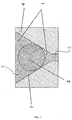
- FIG. 1 shows the section through a stent structure with a marker 3 incorporated therein in accordance with a first exemplary embodiment. It is a wedge-shaped recess formed with a slope 7 in a stent wall 4. In addition, the wedge-shaped recess 5 opens into an opening 2, which forms a passage to an opposite side of the stent structure.
- the recess 5 and the opening 2 can be formed for example by a laser processing of the stent structure.
- a cooled liquid or a fluid is passed through the tubular stent, so that a laser beam passing through the tube wall of the stent is refracted inside the tube.
- a mechanical machining method such as milling, drilling and grinding or eroding can also be used.
- a suitable strip material as a X-ray-visible marker 3 are inserted.
- This strip material has a rectangular or a circular cross-sectional shape.
- the cross section of the strip material is not limited thereto. In particular, it may also have an ellipse shape or a triangular shape, or other polygonal shape.
- the ribbon-like marker 3 abuts the bevels 7 of the wedge shape of the recess 5.
- the marker 3 is self-centering, so that an adjustment of the marker 3 within the recess 5 is superfluous.
- the marker 3 consists for example of tantalum or another radiopaque material.
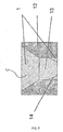
- Fig. 2 shows a second embodiment similar to the first embodiment shown in Fig. 1. The same features of the second embodiment will therefore not be explained again.
- the difference of the second embodiment from the first embodiment is that the opening 2 of the first embodiment is not formed in the second embodiment of FIG. This has the advantage that the polymer material 1 must be introduced only from one side.
- the recess 5 has a substantially rectangular shape with a uniform width B.
- the recess 5 is reduced in its width to a smaller width b in a central region.
- the width b is slightly less than the thickness of the strip material of the marker 3, so that the marker 3 can be clamped in the recess 5. In this way, in turn, an automatic centering of the marker within the stent structure.
- the marker 3 need not have a circular cross-sectional shape, but may also have a rectangular or square or any other shape as long as the sides of the Marker 3, which engage with the walls 8 of the stent structure, are slightly rounded to engage with the recess 5 at the narrowed location with the width b in the press fit.
- the advantage of this embodiment lies in a uniformly acting fixing force of the polymer 1 in both an upward and in a downward direction. Since this embodiment leads to a symmetrical cross-sectional shape of the stent structure, the radiopacity is particularly advantageous pronounced.
- the recess 5 in a central region on a projection 31 and the marker 10 is provided with a recess 11.
- the shape of the projection 31 of the recess 5 is adapted to the shape of the recess 11 of the marker 10 so that the marker 10 can snap into the projection 31 of the recess 5.
- the marker 10 is already fixed in the recess 5 of the stent structure.
- the final fixation is then in turn by introducing a polymer material 1.
- By snapping the marker 10 in the recess 5 is a pre-fixing, so that a fixation of the marker 10 during casting with the polymer material 1 is not necessary.
- the production of the stent with the marker 10 fixed therein can be simplified.
- the cross section of the stent structure of the fourth embodiment has a symmetrical shape, the radiopacity is particularly advantageous.
- the pre-fixing of the fourth embodiment is not limited to the formation of the projection 31 and the recess 11. Any other snap connection between the strip material of the marker 10 and the recess 5 of the stent structure may also be used.
- the strip material 10 may have a projection and the recess 5 a recess.
- a band material having a substantially square cross section is used as a marker 13.
- the square cross section of the marker 13 is provided in a direction of insertion of the marker 13 with a slope 14 for facilitating the insertion of the marker 13.
- the recess 5 of the stent structure is wedge-shaped in an upper region and formed in a lower region with a uniform width.
- the width of the recess 5 is preferably dimensioned slightly smaller than the width of the marker 13, so that a clamping connection between the marker 13 and the recess 5 of the stent structure comes about.
- a residual volume of the recess 5 is in turn potted by a polymer material 1.
- Polytetrafluoroethylene, fluoroethylene propylene, polyvinyl fluoride, polyether urethane, polyester urethane, polycarbonate urethane, silicone, polyphosphazenes, polyphosphoric esters, polyactides, polyanhydrides, polyimide, polyethylene, polypropylene, ethylene vinyl acetate, polyether ketones, polyaryl ether ketones or polysulfones are particularly suitable as a polymer material for all embodiments 1 to 5 described hitherto.
- Tungsten, tantalum, gold, platinum, niobium, palladium, silver, iridium and alloys thereof are particularly suitable as the material for the markers 3, 10, 13.
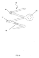
- the recesses 5 within the stent structure may be attached to various locations of a stent. As shown in Fig. 6, the recesses 5 may be attached to a vertex 16, a ridge or cell connector 17 or to a web 19 of a stent structure. In addition, the recesses 5 can be attached to stent ends 18.
- FIG. 7 shows a view AA of FIG. 2.
- the recess 5 has different shapes in the longitudinal direction.
- the recess 5 may have at its ends a region of increased width.
- the width of the recess 5 may vary wavy, so that the marker 3, 6, 13, 20 is clamped to the wave projections of the recess 5.
- the recess 5 may have a sawtooth profile, so that the marker 3, 6, 13, 20 is clamped with the teeth of the recess.
- the recess 5 may have any other shape.
- the marker should only be clamped at spaced apart locations in the longitudinal direction of the stent structure by protrusions of the recess so that pre-fixation can be achieved prior to casting with the polymer 1.
- a zig-zag profile is also suitable for this purpose.
- band material offers the advantage that not only individual sites such as ends of the stent structure can be made visible by the marker, but the entire stent structure can be made visible when the band material extends over a greater length of the webs of a stent structure.
- the invention is not limited to nitinol stents, but may be applied to stents of other materials. Examples include stents made of stainless steel or cobalt-chromium.
- the invention offers the particular advantage that the strip material for the formation of the marker over a marker made of a polymer with X-ray-visible powder has an increased improved radiopacity. Compared with attaching a marker by laser welding and coating the stent structure, the present invention provides a simplified method of attaching a marker to a stent structure.
- the marker is not limited to the tape material described here.
- the marker may have any other shape, such as the shape of a ball, a pin or a cone. All that matters is that a solid of a radiopaque material is placed in a recess of the stent structure and potted with a polymer.
- the recess may have any suitable shape to the solid form, for example a cylindrical shape, a conical shape or a shape with projections and / or depressions to form a snap connection.
Applications Claiming Priority (1)
| Application Number | Priority Date | Filing Date | Title |
|---|---|---|---|
| DE102004054084A DE102004054084B4 (de) | 2004-11-09 | 2004-11-09 | Stent mit einem Marker zur Verbesserung der Röntgensichtbarkeit, die Verwendung sowie ein Verfahren zum Herstellen eines derartigen Stents |
Publications (2)
| Publication Number | Publication Date |
|---|---|
| EP1656905A1 true EP1656905A1 (fr) | 2006-05-17 |
| EP1656905B1 EP1656905B1 (fr) | 2006-12-27 |
Family
ID=35431529
Family Applications (1)
| Application Number | Title | Priority Date | Filing Date |
|---|---|---|---|
| EP05019459A Active EP1656905B1 (fr) | 2004-11-09 | 2005-09-07 | Procédé pour attacher des marqueurs radio-opaques au stent |
Country Status (3)
| Country | Link |
|---|---|
| EP (1) | EP1656905B1 (fr) |
| AT (1) | ATE349189T1 (fr) |
| DE (2) | DE102004054084B4 (fr) |
Cited By (11)
| Publication number | Priority date | Publication date | Assignee | Title |
|---|---|---|---|---|
| WO2007081551A1 (fr) * | 2006-01-04 | 2007-07-19 | Abbot Cardiovascular Systems Inc. | Endoprothèses vasculaires avec marqueurs radio-opaques |
| WO2008036380A1 (fr) | 2006-09-21 | 2008-03-27 | Boston Scientific Limited | Stent comportant un élément support |
| FR2957240A1 (fr) * | 2010-03-10 | 2011-09-16 | Philippe Laheurte | Dispositif medical equipe d'un module d'identification rfid |
| EP2881088A1 (fr) * | 2013-12-04 | 2015-06-10 | Admedes Schuessler GmbH | Implant contenant un marqueur |
| US9694116B2 (en) | 2006-05-26 | 2017-07-04 | Abbott Cardiovascular Systems Inc. | Stents with radiopaque markers |
| US9737368B2 (en) | 2015-02-24 | 2017-08-22 | Abbott Cardiovascular Systems Inc. | System and method for attaching a radiopaque marker bead to an endoprosthesis |
| US9763818B2 (en) | 2010-01-30 | 2017-09-19 | Abbott Cardiovascular Systems Inc. | Method of crimping stent on catheter delivery assembly |
| US9827119B2 (en) | 2010-01-30 | 2017-11-28 | Abbott Cardiovascular Systems Inc. | Polymer scaffolds having a low crossing profile |
| US9999527B2 (en) | 2015-02-11 | 2018-06-19 | Abbott Cardiovascular Systems Inc. | Scaffolds having radiopaque markers |
| US10307274B2 (en) | 2011-07-29 | 2019-06-04 | Abbott Cardiovascular Systems Inc. | Methods for uniform crimping and deployment of a polymer scaffold |
| US10610387B2 (en) | 2015-06-12 | 2020-04-07 | Abbott Cardiovascular Systems Inc. | Scaffolds having a radiopaque marker and methods for attaching a marker to a scaffold |
Families Citing this family (4)
| Publication number | Priority date | Publication date | Assignee | Title |
|---|---|---|---|---|
| DE102007031796A1 (de) * | 2007-07-07 | 2009-01-08 | WRW Consulting GbR (Vertretungsberechtigter Gesellschafter: Dr. Walter Reith, 66424 Homburg) | Radial expandierbares System für den Einsatz in Körperröhren |
| DE102010021962A1 (de) * | 2010-05-28 | 2011-12-01 | Siemens Aktiengesellschaft | Medizinisches Implantat mit Röntgenmarker |
| DE102012107261B4 (de) * | 2012-08-08 | 2015-11-12 | Acandis Gmbh & Co. Kg | Medizinische Vorrichtung zur Einfuhr in einen lebenden Körper und Verfahren zum Herstellen einer derartigen Vorrichtung |
| US11147694B1 (en) | 2021-03-26 | 2021-10-19 | Vesper Medical, Inc. | Medical implants with structural members having barbs for retaining radiopaque markers |
Citations (6)
| Publication number | Priority date | Publication date | Assignee | Title |
|---|---|---|---|---|
| US6293966B1 (en) * | 1997-05-06 | 2001-09-25 | Cook Incorporated | Surgical stent featuring radiopaque markers |
| WO2002026162A2 (fr) * | 2000-09-26 | 2002-04-04 | Advanced Cardiovascular Systems, Inc. | Procede de chargement d'une substance sur un dispositif implantable |
| DE10064596A1 (de) * | 2000-12-18 | 2002-06-20 | Biotronik Mess & Therapieg | Verfahren zum Anbringen eines Markerelements an einem Implantat sowie mit einem Markerelement versehenes Implantat |
| WO2003015664A1 (fr) * | 2001-08-20 | 2003-02-27 | Conor Medsystems, Inc. | Dispositif medical extensible destine a l'apport d'un agent utile |
| US20040088039A1 (en) * | 2002-11-01 | 2004-05-06 | Lee Nathan T. | Method of securing radiopaque markers to an implant |
| DE202004014789U1 (de) * | 2004-09-22 | 2005-01-27 | Campus Medizin & Technik Gmbh | Stent zur Implantation in oder um ein Hohlorgan mit Markerelementen aus einem röntgenopaken Material |
Family Cites Families (4)
| Publication number | Priority date | Publication date | Assignee | Title |
|---|---|---|---|---|
| US6022374A (en) * | 1997-12-16 | 2000-02-08 | Cardiovasc, Inc. | Expandable stent having radiopaque marker and method |
| US6585765B1 (en) * | 2000-06-29 | 2003-07-01 | Advanced Cardiovascular Systems, Inc. | Implantable device having substances impregnated therein and a method of impregnating the same |
| US6863685B2 (en) * | 2001-03-29 | 2005-03-08 | Cordis Corporation | Radiopacity intraluminal medical device |
| US6945995B2 (en) * | 2002-08-29 | 2005-09-20 | Boston Scientific Scimed, Inc. | Stent overlap point markers |
-
2004
- 2004-11-09 DE DE102004054084A patent/DE102004054084B4/de active Active
-
2005
- 2005-09-07 EP EP05019459A patent/EP1656905B1/fr active Active
- 2005-09-07 AT AT05019459T patent/ATE349189T1/de active
- 2005-09-07 DE DE502005000264T patent/DE502005000264D1/de active Active
Patent Citations (6)
| Publication number | Priority date | Publication date | Assignee | Title |
|---|---|---|---|---|
| US6293966B1 (en) * | 1997-05-06 | 2001-09-25 | Cook Incorporated | Surgical stent featuring radiopaque markers |
| WO2002026162A2 (fr) * | 2000-09-26 | 2002-04-04 | Advanced Cardiovascular Systems, Inc. | Procede de chargement d'une substance sur un dispositif implantable |
| DE10064596A1 (de) * | 2000-12-18 | 2002-06-20 | Biotronik Mess & Therapieg | Verfahren zum Anbringen eines Markerelements an einem Implantat sowie mit einem Markerelement versehenes Implantat |
| WO2003015664A1 (fr) * | 2001-08-20 | 2003-02-27 | Conor Medsystems, Inc. | Dispositif medical extensible destine a l'apport d'un agent utile |
| US20040088039A1 (en) * | 2002-11-01 | 2004-05-06 | Lee Nathan T. | Method of securing radiopaque markers to an implant |
| DE202004014789U1 (de) * | 2004-09-22 | 2005-01-27 | Campus Medizin & Technik Gmbh | Stent zur Implantation in oder um ein Hohlorgan mit Markerelementen aus einem röntgenopaken Material |
Cited By (18)
| Publication number | Priority date | Publication date | Assignee | Title |
|---|---|---|---|---|
| US10070975B2 (en) | 2006-01-04 | 2018-09-11 | Abbott Cardiovascular Systems Inc. | Stents with radiopaque markers |
| WO2007081551A1 (fr) * | 2006-01-04 | 2007-07-19 | Abbot Cardiovascular Systems Inc. | Endoprothèses vasculaires avec marqueurs radio-opaques |
| US9694116B2 (en) | 2006-05-26 | 2017-07-04 | Abbott Cardiovascular Systems Inc. | Stents with radiopaque markers |
| WO2008036380A1 (fr) | 2006-09-21 | 2008-03-27 | Boston Scientific Limited | Stent comportant un élément support |
| US7875069B2 (en) | 2006-09-21 | 2011-01-25 | Boston Scientific Scimed, Inc. | Stent with support element |
| US9770351B2 (en) | 2010-01-30 | 2017-09-26 | Abbott Cardiovascular Systems Inc. | Crush recoverable polymer scaffolds |
| US9763818B2 (en) | 2010-01-30 | 2017-09-19 | Abbott Cardiovascular Systems Inc. | Method of crimping stent on catheter delivery assembly |
| US9827119B2 (en) | 2010-01-30 | 2017-11-28 | Abbott Cardiovascular Systems Inc. | Polymer scaffolds having a low crossing profile |
| US9867728B2 (en) | 2010-01-30 | 2018-01-16 | Abbott Cardiovascular Systems Inc. | Method of making a stent |
| US10123894B2 (en) | 2010-01-30 | 2018-11-13 | Abbott Cardiovascular Systems Inc. | Method of crimping stent on catheter delivery assembly |
| US11324614B2 (en) | 2010-01-30 | 2022-05-10 | Abbott Cardiovascular Systems Inc. | Balloon expanded polymer stent |
| FR2957240A1 (fr) * | 2010-03-10 | 2011-09-16 | Philippe Laheurte | Dispositif medical equipe d'un module d'identification rfid |
| US10307274B2 (en) | 2011-07-29 | 2019-06-04 | Abbott Cardiovascular Systems Inc. | Methods for uniform crimping and deployment of a polymer scaffold |
| EP2881088A1 (fr) * | 2013-12-04 | 2015-06-10 | Admedes Schuessler GmbH | Implant contenant un marqueur |
| US9999527B2 (en) | 2015-02-11 | 2018-06-19 | Abbott Cardiovascular Systems Inc. | Scaffolds having radiopaque markers |
| US9737368B2 (en) | 2015-02-24 | 2017-08-22 | Abbott Cardiovascular Systems Inc. | System and method for attaching a radiopaque marker bead to an endoprosthesis |
| US10610387B2 (en) | 2015-06-12 | 2020-04-07 | Abbott Cardiovascular Systems Inc. | Scaffolds having a radiopaque marker and methods for attaching a marker to a scaffold |
| US11478370B2 (en) | 2015-06-12 | 2022-10-25 | Abbott Cardiovascular Systems Inc. | Scaffolds having a radiopaque marker and methods for attaching a marker to a scaffold |
Also Published As
| Publication number | Publication date |
|---|---|
| EP1656905B1 (fr) | 2006-12-27 |
| DE102004054084B4 (de) | 2007-08-02 |
| DE102004054084A1 (de) | 2006-05-11 |
| ATE349189T1 (de) | 2007-01-15 |
| DE502005000264D1 (de) | 2007-02-08 |
Similar Documents
| Publication | Publication Date | Title |
|---|---|---|
| EP1656905B1 (fr) | Procédé pour attacher des marqueurs radio-opaques au stent | |
| DE69731514T2 (de) | Expandierbarer Stent | |
| DE102005039136B4 (de) | Verbesserung der Röntgensichtbarkeit und Korrosionsbeständigkeit von NiTi Stents unter Einsatz von Nieten aus Sandwichmaterial | |
| DE69732992T2 (de) | Stent mit variablen Eigenschaften zur Stützoptimierung | |
| EP1023008B1 (fr) | Extenseur elargi et son procede de fabrication | |
| DE69732229T2 (de) | Stent sowie Herstellungsverfahren dafür | |
| DE602004009994T2 (de) | Stent mit einem angefügten Marker in der Form einer Hülse | |
| DE69630379T2 (de) | Endovaskulärer verzweigter stent | |
| DE60101046T2 (de) | Stentmatrix | |
| EP2134302B1 (fr) | Implant pour agir sur le flux sanguin | |
| DE60031490T2 (de) | Stents für Angioplastie | |
| DE69738023T2 (de) | Intravaskulärer stent | |
| DE69934244T2 (de) | Spiralförmiger stent | |
| DE69831575T2 (de) | Stent mit variabler ausbreitungskraft | |
| EP2257248B1 (fr) | Endoprothèse vasculaire et son procédé de fabrication | |
| DE102004045994A1 (de) | Stent zur Implantation in oder um ein Hohlorgan mit Markerelementen aus einem röntgenopaken Material | |
| DE102018131269B4 (de) | Medizinische Vorrichtung zur Einfuhr in ein Körperhohlorgan und Herstellungsverfahren | |
| DE10317241A1 (de) | Stent | |
| DE202004014789U1 (de) | Stent zur Implantation in oder um ein Hohlorgan mit Markerelementen aus einem röntgenopaken Material | |
| EP1844740B1 (fr) | Stent auto-extensible doté d'une structure à ressort | |
| DE102010046408B4 (de) | Zuführsystem | |
| DE102018133345B4 (de) | Stent | |
| DE102011115238B4 (de) | Körperimplantat mit verbesserter Röntgensichtbarkeit, Kombination aus einem Katheter, einem Führungsdraht und einem Körperimplantat und Verfahren zum Erhöhen der Röntgensichtbarkeit eines Körperimplantats | |
| DE102012109736A1 (de) | Medizinische, intravaskulär einsetzbare Vorrichtung, Zuführsystem und Verfahren zur Herstellung einer derartigen Vorrichtung | |
| DE102013113271B4 (de) | Medizinisches Implantat, Behandlungssystem mit einem derartigen Implantat und Verfahren zum Herstellen eines Implantats |
Legal Events
| Date | Code | Title | Description |
|---|---|---|---|
| PUAI | Public reference made under article 153(3) epc to a published international application that has entered the european phase |
Free format text: ORIGINAL CODE: 0009012 |
|
| 17P | Request for examination filed |
Effective date: 20060216 |
|
| AK | Designated contracting states |
Kind code of ref document: A1 Designated state(s): AT BE BG CH CY CZ DE DK EE ES FI FR GB GR HU IE IS IT LI LT LU LV MC NL PL PT RO SE SI SK TR |
|
| AX | Request for extension of the european patent |
Extension state: AL BA HR MK YU |
|
| GRAP | Despatch of communication of intention to grant a patent |
Free format text: ORIGINAL CODE: EPIDOSNIGR1 |
|
| GRAS | Grant fee paid |
Free format text: ORIGINAL CODE: EPIDOSNIGR3 |
|
| GRAA | (expected) grant |
Free format text: ORIGINAL CODE: 0009210 |
|
| AK | Designated contracting states |
Kind code of ref document: B1 Designated state(s): AT BE BG CH CY CZ DE DK EE ES FI FR GB GR HU IE IS IT LI LT LU LV MC NL PL PT RO SE SI SK TR |
|
| PG25 | Lapsed in a contracting state [announced via postgrant information from national office to epo] |
Ref country code: CZ Free format text: LAPSE BECAUSE OF FAILURE TO SUBMIT A TRANSLATION OF THE DESCRIPTION OR TO PAY THE FEE WITHIN THE PRESCRIBED TIME-LIMIT Effective date: 20061227 Ref country code: LT Free format text: LAPSE BECAUSE OF FAILURE TO SUBMIT A TRANSLATION OF THE DESCRIPTION OR TO PAY THE FEE WITHIN THE PRESCRIBED TIME-LIMIT Effective date: 20061227 Ref country code: DK Free format text: LAPSE BECAUSE OF FAILURE TO SUBMIT A TRANSLATION OF THE DESCRIPTION OR TO PAY THE FEE WITHIN THE PRESCRIBED TIME-LIMIT Effective date: 20061227 Ref country code: SI Free format text: LAPSE BECAUSE OF FAILURE TO SUBMIT A TRANSLATION OF THE DESCRIPTION OR TO PAY THE FEE WITHIN THE PRESCRIBED TIME-LIMIT Effective date: 20061227 Ref country code: PL Free format text: LAPSE BECAUSE OF FAILURE TO SUBMIT A TRANSLATION OF THE DESCRIPTION OR TO PAY THE FEE WITHIN THE PRESCRIBED TIME-LIMIT Effective date: 20061227 Ref country code: FI Free format text: LAPSE BECAUSE OF FAILURE TO SUBMIT A TRANSLATION OF THE DESCRIPTION OR TO PAY THE FEE WITHIN THE PRESCRIBED TIME-LIMIT Effective date: 20061227 Ref country code: RO Free format text: LAPSE BECAUSE OF FAILURE TO SUBMIT A TRANSLATION OF THE DESCRIPTION OR TO PAY THE FEE WITHIN THE PRESCRIBED TIME-LIMIT Effective date: 20061227 Ref country code: NL Free format text: LAPSE BECAUSE OF FAILURE TO SUBMIT A TRANSLATION OF THE DESCRIPTION OR TO PAY THE FEE WITHIN THE PRESCRIBED TIME-LIMIT Effective date: 20061227 Ref country code: SK Free format text: LAPSE BECAUSE OF FAILURE TO SUBMIT A TRANSLATION OF THE DESCRIPTION OR TO PAY THE FEE WITHIN THE PRESCRIBED TIME-LIMIT Effective date: 20061227 |
|
| REG | Reference to a national code |
Ref country code: GB Ref legal event code: FG4D Free format text: NOT ENGLISH |
|
| AKX | Designation fees paid |
Designated state(s): AT BE BG CH CY CZ DE DK EE ES FI FR GB GR HU IE IS IT LI LT LU LV MC NL PL PT RO SE SI SK TR |
|
| REG | Reference to a national code |
Ref country code: IE Ref legal event code: FG4D Free format text: LANGUAGE OF EP DOCUMENT: GERMAN |
|
| REF | Corresponds to: |
Ref document number: 502005000264 Country of ref document: DE Date of ref document: 20070208 Kind code of ref document: P |
|
| PG25 | Lapsed in a contracting state [announced via postgrant information from national office to epo] |
Ref country code: BG Free format text: LAPSE BECAUSE OF FAILURE TO SUBMIT A TRANSLATION OF THE DESCRIPTION OR TO PAY THE FEE WITHIN THE PRESCRIBED TIME-LIMIT Effective date: 20070327 Ref country code: SE Free format text: LAPSE BECAUSE OF FAILURE TO SUBMIT A TRANSLATION OF THE DESCRIPTION OR TO PAY THE FEE WITHIN THE PRESCRIBED TIME-LIMIT Effective date: 20070327 |
|
| PG25 | Lapsed in a contracting state [announced via postgrant information from national office to epo] |
Ref country code: ES Free format text: LAPSE BECAUSE OF FAILURE TO SUBMIT A TRANSLATION OF THE DESCRIPTION OR TO PAY THE FEE WITHIN THE PRESCRIBED TIME-LIMIT Effective date: 20070407 |
|
| GBT | Gb: translation of ep patent filed (gb section 77(6)(a)/1977) |
Effective date: 20070315 |
|
| PG25 | Lapsed in a contracting state [announced via postgrant information from national office to epo] |
Ref country code: IS Free format text: LAPSE BECAUSE OF FAILURE TO SUBMIT A TRANSLATION OF THE DESCRIPTION OR TO PAY THE FEE WITHIN THE PRESCRIBED TIME-LIMIT Effective date: 20070427 |
|
| ET | Fr: translation filed | ||
| PG25 | Lapsed in a contracting state [announced via postgrant information from national office to epo] |
Ref country code: PT Free format text: LAPSE BECAUSE OF FAILURE TO SUBMIT A TRANSLATION OF THE DESCRIPTION OR TO PAY THE FEE WITHIN THE PRESCRIBED TIME-LIMIT Effective date: 20070528 |
|
| NLV1 | Nl: lapsed or annulled due to failure to fulfill the requirements of art. 29p and 29m of the patents act | ||
| PLBE | No opposition filed within time limit |
Free format text: ORIGINAL CODE: 0009261 |
|
| STAA | Information on the status of an ep patent application or granted ep patent |
Free format text: STATUS: NO OPPOSITION FILED WITHIN TIME LIMIT |
|
| 26N | No opposition filed |
Effective date: 20070928 |
|
| PG25 | Lapsed in a contracting state [announced via postgrant information from national office to epo] |
Ref country code: LV Free format text: LAPSE BECAUSE OF FAILURE TO SUBMIT A TRANSLATION OF THE DESCRIPTION OR TO PAY THE FEE WITHIN THE PRESCRIBED TIME-LIMIT Effective date: 20061227 |
|
| PG25 | Lapsed in a contracting state [announced via postgrant information from national office to epo] |
Ref country code: MC Free format text: LAPSE BECAUSE OF NON-PAYMENT OF DUE FEES Effective date: 20070930 Ref country code: GR Free format text: LAPSE BECAUSE OF FAILURE TO SUBMIT A TRANSLATION OF THE DESCRIPTION OR TO PAY THE FEE WITHIN THE PRESCRIBED TIME-LIMIT Effective date: 20070328 |
|
| PG25 | Lapsed in a contracting state [announced via postgrant information from national office to epo] |
Ref country code: EE Free format text: LAPSE BECAUSE OF FAILURE TO SUBMIT A TRANSLATION OF THE DESCRIPTION OR TO PAY THE FEE WITHIN THE PRESCRIBED TIME-LIMIT Effective date: 20061227 |
|
| PG25 | Lapsed in a contracting state [announced via postgrant information from national office to epo] |
Ref country code: LU Free format text: LAPSE BECAUSE OF NON-PAYMENT OF DUE FEES Effective date: 20070907 Ref country code: CY Free format text: LAPSE BECAUSE OF FAILURE TO SUBMIT A TRANSLATION OF THE DESCRIPTION OR TO PAY THE FEE WITHIN THE PRESCRIBED TIME-LIMIT Effective date: 20061227 |
|
| PG25 | Lapsed in a contracting state [announced via postgrant information from national office to epo] |
Ref country code: HU Free format text: LAPSE BECAUSE OF FAILURE TO SUBMIT A TRANSLATION OF THE DESCRIPTION OR TO PAY THE FEE WITHIN THE PRESCRIBED TIME-LIMIT Effective date: 20070628 Ref country code: TR Free format text: LAPSE BECAUSE OF FAILURE TO SUBMIT A TRANSLATION OF THE DESCRIPTION OR TO PAY THE FEE WITHIN THE PRESCRIBED TIME-LIMIT Effective date: 20061227 |
|
| PGFP | Annual fee paid to national office [announced via postgrant information from national office to epo] |
Ref country code: CH Payment date: 20140829 Year of fee payment: 10 |
|
| PGFP | Annual fee paid to national office [announced via postgrant information from national office to epo] |
Ref country code: AT Payment date: 20140630 Year of fee payment: 10 |
|
| PGFP | Annual fee paid to national office [announced via postgrant information from national office to epo] |
Ref country code: BE Payment date: 20140715 Year of fee payment: 10 |
|
| PGFP | Annual fee paid to national office [announced via postgrant information from national office to epo] |
Ref country code: IT Payment date: 20140926 Year of fee payment: 10 |
|
| PG25 | Lapsed in a contracting state [announced via postgrant information from national office to epo] |
Ref country code: IT Free format text: LAPSE BECAUSE OF NON-PAYMENT OF DUE FEES Effective date: 20150907 |
|
| REG | Reference to a national code |
Ref country code: CH Ref legal event code: PL |
|
| REG | Reference to a national code |
Ref country code: AT Ref legal event code: MM01 Ref document number: 349189 Country of ref document: AT Kind code of ref document: T Effective date: 20150907 |
|
| PG25 | Lapsed in a contracting state [announced via postgrant information from national office to epo] |
Ref country code: LI Free format text: LAPSE BECAUSE OF NON-PAYMENT OF DUE FEES Effective date: 20150930 Ref country code: CH Free format text: LAPSE BECAUSE OF NON-PAYMENT OF DUE FEES Effective date: 20150930 |
|
| PG25 | Lapsed in a contracting state [announced via postgrant information from national office to epo] |
Ref country code: AT Free format text: LAPSE BECAUSE OF NON-PAYMENT OF DUE FEES Effective date: 20150907 |
|
| REG | Reference to a national code |
Ref country code: FR Ref legal event code: PLFP Year of fee payment: 12 |
|
| PG25 | Lapsed in a contracting state [announced via postgrant information from national office to epo] |
Ref country code: BE Free format text: LAPSE BECAUSE OF NON-PAYMENT OF DUE FEES Effective date: 20150930 |
|
| REG | Reference to a national code |
Ref country code: FR Ref legal event code: PLFP Year of fee payment: 13 |
|
| REG | Reference to a national code |
Ref country code: FR Ref legal event code: PLFP Year of fee payment: 14 |
|
| PGFP | Annual fee paid to national office [announced via postgrant information from national office to epo] |
Ref country code: IE Payment date: 20220919 Year of fee payment: 18 Ref country code: GB Payment date: 20220923 Year of fee payment: 18 Ref country code: DE Payment date: 20220622 Year of fee payment: 18 |
|
| PGFP | Annual fee paid to national office [announced via postgrant information from national office to epo] |
Ref country code: FR Payment date: 20220923 Year of fee payment: 18 |