EP1656793B1 - Schichtlage in video codec - Google Patents
Schichtlage in video codec Download PDFInfo
- Publication number
- EP1656793B1 EP1656793B1 EP04783323.1A EP04783323A EP1656793B1 EP 1656793 B1 EP1656793 B1 EP 1656793B1 EP 04783323 A EP04783323 A EP 04783323A EP 1656793 B1 EP1656793 B1 EP 1656793B1
- Authority
- EP
- European Patent Office
- Prior art keywords
- slice
- picture
- video
- coding
- decoding
- Prior art date
- Legal status (The legal status is an assumption and is not a legal conclusion. Google has not performed a legal analysis and makes no representation as to the accuracy of the status listed.)
- Expired - Lifetime
Links
- 238000000034 method Methods 0.000 claims description 49
- 238000001914 filtration Methods 0.000 claims description 42
- 238000009499 grossing Methods 0.000 claims description 20
- 238000012545 processing Methods 0.000 claims description 13
- 238000005538 encapsulation Methods 0.000 claims description 9
- 230000007246 mechanism Effects 0.000 claims description 7
- 230000011664 signaling Effects 0.000 claims 3
- 230000006835 compression Effects 0.000 description 25
- 238000007906 compression Methods 0.000 description 25
- 238000010586 diagram Methods 0.000 description 20
- 239000013598 vector Substances 0.000 description 18
- 230000005540 biological transmission Effects 0.000 description 17
- 239000000872 buffer Substances 0.000 description 15
- 230000008569 process Effects 0.000 description 14
- 238000013139 quantization Methods 0.000 description 14
- 238000001514 detection method Methods 0.000 description 13
- 238000004891 communication Methods 0.000 description 9
- 230000003595 spectral effect Effects 0.000 description 7
- 230000003044 adaptive effect Effects 0.000 description 6
- 230000002265 prevention Effects 0.000 description 6
- 230000000875 corresponding effect Effects 0.000 description 4
- 230000000750 progressive effect Effects 0.000 description 4
- 230000007423 decrease Effects 0.000 description 3
- 238000000605 extraction Methods 0.000 description 3
- 241000023320 Luma <angiosperm> Species 0.000 description 2
- 238000013459 approach Methods 0.000 description 2
- 230000008901 benefit Effects 0.000 description 2
- 238000012937 correction Methods 0.000 description 2
- 230000006837 decompression Effects 0.000 description 2
- 230000000694 effects Effects 0.000 description 2
- OSWPMRLSEDHDFF-UHFFFAOYSA-N methyl salicylate Chemical compound COC(=O)C1=CC=CC=C1O OSWPMRLSEDHDFF-UHFFFAOYSA-N 0.000 description 2
- 230000009466 transformation Effects 0.000 description 2
- 238000000844 transformation Methods 0.000 description 2
- 230000000903 blocking effect Effects 0.000 description 1
- 230000002596 correlated effect Effects 0.000 description 1
- 230000008878 coupling Effects 0.000 description 1
- 238000010168 coupling process Methods 0.000 description 1
- 238000005859 coupling reaction Methods 0.000 description 1
- 230000003247 decreasing effect Effects 0.000 description 1
- 238000013461 design Methods 0.000 description 1
- 230000006870 function Effects 0.000 description 1
- 239000003550 marker Substances 0.000 description 1
- 239000011159 matrix material Substances 0.000 description 1
- 230000003287 optical effect Effects 0.000 description 1
- 230000000153 supplemental effect Effects 0.000 description 1
- 230000002123 temporal effect Effects 0.000 description 1
Images


Classifications
-
- H—ELECTRICITY
- H04—ELECTRIC COMMUNICATION TECHNIQUE
- H04N—PICTORIAL COMMUNICATION, e.g. TELEVISION
- H04N19/00—Methods or arrangements for coding, decoding, compressing or decompressing digital video signals
- H04N19/85—Methods or arrangements for coding, decoding, compressing or decompressing digital video signals using pre-processing or post-processing specially adapted for video compression
- H04N19/86—Methods or arrangements for coding, decoding, compressing or decompressing digital video signals using pre-processing or post-processing specially adapted for video compression involving reduction of coding artifacts, e.g. of blockiness
-
- H—ELECTRICITY
- H04—ELECTRIC COMMUNICATION TECHNIQUE
- H04N—PICTORIAL COMMUNICATION, e.g. TELEVISION
- H04N19/00—Methods or arrangements for coding, decoding, compressing or decompressing digital video signals
- H04N19/10—Methods or arrangements for coding, decoding, compressing or decompressing digital video signals using adaptive coding
- H04N19/102—Methods or arrangements for coding, decoding, compressing or decompressing digital video signals using adaptive coding characterised by the element, parameter or selection affected or controlled by the adaptive coding
- H04N19/103—Selection of coding mode or of prediction mode
- H04N19/105—Selection of the reference unit for prediction within a chosen coding or prediction mode, e.g. adaptive choice of position and number of pixels used for prediction
-
- H—ELECTRICITY
- H04—ELECTRIC COMMUNICATION TECHNIQUE
- H04N—PICTORIAL COMMUNICATION, e.g. TELEVISION
- H04N19/00—Methods or arrangements for coding, decoding, compressing or decompressing digital video signals
- H04N19/10—Methods or arrangements for coding, decoding, compressing or decompressing digital video signals using adaptive coding
- H04N19/102—Methods or arrangements for coding, decoding, compressing or decompressing digital video signals using adaptive coding characterised by the element, parameter or selection affected or controlled by the adaptive coding
- H04N19/103—Selection of coding mode or of prediction mode
- H04N19/107—Selection of coding mode or of prediction mode between spatial and temporal predictive coding, e.g. picture refresh
-
- H—ELECTRICITY
- H04—ELECTRIC COMMUNICATION TECHNIQUE
- H04N—PICTORIAL COMMUNICATION, e.g. TELEVISION
- H04N19/00—Methods or arrangements for coding, decoding, compressing or decompressing digital video signals
- H04N19/10—Methods or arrangements for coding, decoding, compressing or decompressing digital video signals using adaptive coding
- H04N19/134—Methods or arrangements for coding, decoding, compressing or decompressing digital video signals using adaptive coding characterised by the element, parameter or criterion affecting or controlling the adaptive coding
- H04N19/164—Feedback from the receiver or from the transmission channel
- H04N19/166—Feedback from the receiver or from the transmission channel concerning the amount of transmission errors, e.g. bit error rate [BER]
-
- H—ELECTRICITY
- H04—ELECTRIC COMMUNICATION TECHNIQUE
- H04N—PICTORIAL COMMUNICATION, e.g. TELEVISION
- H04N19/00—Methods or arrangements for coding, decoding, compressing or decompressing digital video signals
- H04N19/10—Methods or arrangements for coding, decoding, compressing or decompressing digital video signals using adaptive coding
- H04N19/169—Methods or arrangements for coding, decoding, compressing or decompressing digital video signals using adaptive coding characterised by the coding unit, i.e. the structural portion or semantic portion of the video signal being the object or the subject of the adaptive coding
- H04N19/17—Methods or arrangements for coding, decoding, compressing or decompressing digital video signals using adaptive coding characterised by the coding unit, i.e. the structural portion or semantic portion of the video signal being the object or the subject of the adaptive coding the unit being an image region, e.g. an object
- H04N19/174—Methods or arrangements for coding, decoding, compressing or decompressing digital video signals using adaptive coding characterised by the coding unit, i.e. the structural portion or semantic portion of the video signal being the object or the subject of the adaptive coding the unit being an image region, e.g. an object the region being a slice, e.g. a line of blocks or a group of blocks
-
- H—ELECTRICITY
- H04—ELECTRIC COMMUNICATION TECHNIQUE
- H04N—PICTORIAL COMMUNICATION, e.g. TELEVISION
- H04N19/00—Methods or arrangements for coding, decoding, compressing or decompressing digital video signals
- H04N19/46—Embedding additional information in the video signal during the compression process
-
- H—ELECTRICITY
- H04—ELECTRIC COMMUNICATION TECHNIQUE
- H04N—PICTORIAL COMMUNICATION, e.g. TELEVISION
- H04N19/00—Methods or arrangements for coding, decoding, compressing or decompressing digital video signals
- H04N19/60—Methods or arrangements for coding, decoding, compressing or decompressing digital video signals using transform coding
- H04N19/61—Methods or arrangements for coding, decoding, compressing or decompressing digital video signals using transform coding in combination with predictive coding
-
- H—ELECTRICITY
- H04—ELECTRIC COMMUNICATION TECHNIQUE
- H04N—PICTORIAL COMMUNICATION, e.g. TELEVISION
- H04N19/00—Methods or arrangements for coding, decoding, compressing or decompressing digital video signals
- H04N19/70—Methods or arrangements for coding, decoding, compressing or decompressing digital video signals characterised by syntax aspects related to video coding, e.g. related to compression standards
-
- H—ELECTRICITY
- H04—ELECTRIC COMMUNICATION TECHNIQUE
- H04N—PICTORIAL COMMUNICATION, e.g. TELEVISION
- H04N19/00—Methods or arrangements for coding, decoding, compressing or decompressing digital video signals
- H04N19/80—Details of filtering operations specially adapted for video compression, e.g. for pixel interpolation
- H04N19/82—Details of filtering operations specially adapted for video compression, e.g. for pixel interpolation involving filtering within a prediction loop
Definitions
- the present invention relates to techniques for digitally encoding, decoding and processing video, images and other digital media content.
- a typical raw digital video sequence includes 15 or 30 frames per second. Each frame can include tens or hundreds of thousands of pixels (also called pels). Each pixel represents a tiny element of the picture.
- a computer commonly represents a pixel as a set of three samples totaling 24 bits.
- a pixel may comprise an 8-bit luminance sample (also called a luma sample) that defines the grayscale component of the pixel and two 8-bit chrominance sample values (also called chroma samples) that define the color component of the pixel.
- the number of bits per second, or bit rate, of a typical raw digital video sequence may be 5 million bits per second or more.
- compression also called coding or encoding
- Compression decreases the cost of storing and transmitting video by converting the video into a lower bit rate form.
- Decompression also called decoding
- a "codec” is an encoder/decoder system. Compression can be lossless, in which quality of the video does not suffer, but decreases in the bit rate are limited by the inherent amount of variability (sometimes called entropy) of the video data. Or, compression can be lossy, in which quality of the video suffers, but achievable decreases in the bit rate are more dramatic. Lossy compression is often used in conjunction with lossless compression - in a system design in which the lossy compression establishes an approximation of information and lossless compression techniques are applied to represent the approximation.
- video compression techniques include "intra-picture” compression and "inter-picture” compression, where a picture is, for example, a progressively scanned video frame, an interlaced video frame (having alternating lines for video fields), or an interlaced video field.
- intra-picture compression techniques compress individual frames (typically called I-frames or key frames)
- inter-picture compression techniques compress frames (typically called predicted frames, P-frames, or B-frames) with reference to preceding and/or following frames (typically called reference or anchor frames).
- the predicted frames may be divided into regions called macroblocks.
- a matching region in a reference frame for a particular macroblock is specified by sending motion vector information for the macroblock.
- a motion vector indicates the location of the region in the reference frame whose pixels are to be used as a predictor for the pixels current macroblock.
- the pixel-by-pixel difference, often called the error signal or residual, between the current macroblock (or the blocks thereof) and the macroblock predictor is derived.
- This error signal usually has lower entropy than the original signal. Therefore, the information can be encoded at a lower rate.
- An encoder performs motion estimation by determining a motion vector for a region of a frame by searching for a matching region in one or more reference frames to use as a predictor.
- An encoder or decoder performs motion compensation by applying the motion vector to find the predictor in the one or more reference frames.
- the motion vector value for a macroblock is often correlated with the motion vectors for spatially surrounding macroblocks.
- compression of the data used to transmit the motion vector information can be achieved by coding the differential between the motion vector and a motion vector predictor formed from neighboring motion vectors.
- blocks of pixels or other spatial domain video data such as residuals are transformed into transform domain data, which is often frequency domain (i.e., spectral) data.
- transform domain data which is often frequency domain (i.e., spectral) data.
- the resulting blocks of spectral data coefficients may be quantized and then entropy encoded.
- a decoder When the data is decompressed prior to the resulting video being displayed, a decoder typically performs the inverse of the compression operations. For example, a decoder may perform entropy decoding, inverse quantization, and an inverse transform while decompressing the data. When motion compensation is used, the decoder (and encoder) reconstruct a frame from one or more previously reconstructed frames (which are now used as reference frames), and the newly reconstructed frame may then be used as a reference frame for motion compensation for later frames.
- Video codecs Numerous companies have produced video codecs. For example, Microsoft Corporation has produced a video encoder and decoder released for Windows Media Video 8. Aside from these products, numerous international standards specify aspects of video decoders and formats for compressed video information. These standards include the H.261, MPEG-1, H.262, H.263, and MPEG-4 standards. Directly or by implication, these standards also specify certain encoder details, but other encoder details are not specified. These products and standards use (or support the use of) different combinations of the compression and decompression techniques described above. In particular, these products and standards provide various techniques for partial picture unit coding.
- a slice is defined to contain one or more contiguous rows of macroblocks in their original left-to-right order.
- a slice begins at the first macroblock of a row, and ends at the last macroblock of the same or another row.
- H.263 (with GOBs being roughly equivalent to slices or with Annex K slice structured coding mode), MPEG-4 part 2 and H.264/JVT/MPEG-4part10, all have slices as part of their syntax. Among these, all of them disable intra prediction and motion vector prediction and most other forms of prediction across slice boundaries for error/loss robustness reasons. Among these, only H.263 (Annex J) and H.264/JVT include loop filters. H.263 handling of interlace is rather primitive (field coding only using Annex W supplemental enhancement indications). H.264 has a more error-robust header structure and allows the encoder to select whether or not loop filtering is to be applied across slice boundaries
- the resynchronization marker placed at the start of a new video packet is distinguishable from all possible VLC code words.
- Header information is also provided at the start of a video packet.
- This header contains the information necessary to restart the decoding process, including the address of the first MB contained in this packet and the quantization parameter (QP) necessary to decode that first MB.
- QP quantization parameter
- the MB number provides the necessary spatial resynchronization while the QP allows the differential decoding process to be resynchronized.
- the header extension code HEC
- the HEC is a single bit to indicate whether additional video object plane (VOP) level information will be available in this header.
- the header extension feature enables the decoder to correctly utilize data contained in the current packet without reference to the packet containing the VOP header.
- Recommendation H.263 Video coding for low bit rate communication
- ITU-T recommendation H.263, 1 February 1998, pages 1 to 167 defines the standard H.263. It defines groups of blocks (GOBs) and slices as well as their corresponding coding structures.
- An advanced prediction mode is also described comprising in particular overlapped motion compensation for luminance.
- a video codec and bitstream syntax described herein includes a slice-layer that is designed to be flexible, and provide an effective combination of error-resilience and compression efficiency.
- This slice-layer provides the following key features:
- the following description is directed to implementations of a slice layer in a video codec and bitstream syntax, which is designed to be flexible and provide an effective combination of error-resilience and compression efficiency.
- An exemplary application of the slice layer coding is in an image or video encoder and decoder. Accordingly, the slice layer coding is described in the context of a generalized image or video encoder and decoder, but alternatively can be incorporated in the bitstream syntax of various other image and video codecs that may vary in details from this exemplary bitstream syntax described below.
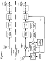
- Figure 1 is a block diagram of a generalized video encoder (100) and Figure 2 is a block diagram of a generalized video decoder (200), in which the WMV9/VC-9 transforms can be incorporated.
- FIG. 1 The relationships shown between modules within the encoder and decoder indicate the main flow of information in the encoder and decoder; other relationships are not shown for the sake of simplicity.
- Figures 1 and 2 usually do not show side information indicating the encoder settings, modes, tables, etc. used for a video sequence, frame, macroblock, block, etc.
- Such side information is sent in the output bitstream, typically after entropy encoding of the side information.
- the format of the output bitstream can be a Windows Media Video format or another format.
- the encoder (100) and decoder (200) are block-based and use a 4:2:0 macroblock format with each macroblock including 4 luminance 8x8 luminance blocks (at times treated as one 16x16 macroblock) and two 8x8 chrominance blocks.
- the encoder (100) and decoder (200) are object-based, use a different macroblock or block format, or perform operations on sets of pixels of different size or configuration than 8x8 blocks and 16x16 macroblocks.
- modules of the encoder or decoder can be added, omitted, split into multiple modules, combined with other modules, and/or replaced with like modules.
- encoder or decoders with different modules and/or other configurations of modules perform one or more of the described techniques.
- Figure 1 is a block diagram of a general video encoder system (100).
- the encoder system (100) receives a sequence of video frames, including a current frame (105), and produces compressed video information (195) as output.
- Particular embodiments of video encoders typically use a variation or supplemented version of the generalized encoder (100).
- the encoder system (100) compresses predicted frames and key frames.
- Figure 1 shows a path for key frames through the encoder system (100) and a path for forward-predicted frames.
- Many of the components of the encoder system (100) are used for compressing both key frames and predicted frames. The exact operations performed by those components can vary depending on the type of information being compressed.
- a predicted frame (also called p-frame, b-frame for bi-directional prediction, or inter-coded frame] is represented in terms of prediction (or difference) from one or more other frames.
- a prediction residual is the difference between what was predicted and the original frame.
- a key frame also called i-frame, intra-coded frame
- a motion estimator (110) estimates motion of macroblocks or other sets of pixels of the current frame (105) with respect to a reference frame, which is the reconstructed previous frame (125) buffered in the frame store (120).
- the reference frame is a later frame or the current frame is bi-directionally predicted.
- the motion estimator (110) outputs as side information motion information (115) such as motion vectors.
- a motion compensator (130) applies the motion information (115) to the reconstructed previous frame (125) to form a motion-compensated current frame (135).
- the prediction is rarely perfect, however, and the difference between the motion-compensated current frame (135) and the original current frame (105) is the prediction residual (145).
- a motion estimator and motion compensator apply another type of motion estimation/compensation.
- a frequency transformer (160) converts the spatial domain video information into frequency domain (i.e., spectral) data.
- the frequency transformer (160) applies a transform described in the following sections that has properties similar to the discrete cosine transform ["DCT"].
- the frequency transformer (160) applies a frequency transform to blocks of spatial prediction residuals for key frames.
- the frequency transformer (160) can apply an 8x8, 8x4, 4x8, or other size frequency transforms.
- a quantizer (170) then quantizes the blocks of spectral data coefficients.
- the quantizer applies uniform, scalar quantization to the spectral data with a step-size that varies on a frame-by-frame basis or other basis.
- the quantizer applies another type of quantization to the spectral data coefficients, for example, a non-uniform, vector, or non-adaptive quantization, or directly quantizes spatial domain data in an encoder system that does not use frequency transformations.
- the encoder (100) can use frame dropping, adaptive filtering, or other techniques for rate control.
- an inverse quantizer (176) When a reconstructed current frame is needed for subsequent motion estimation/compensation, an inverse quantizer (176) performs inverse quantization on the quantized spectral data coefficients. An inverse frequency transformer (166) then performs the inverse of the operations of the frequency transformer (160), producing a reconstructed prediction residual (for a predicted frame) or a reconstructed key frame. If the current frame (105) was a key frame, the reconstructed key frame is taken as the reconstructed current frame (not shown). If the current frame (105) was a predicted frame, the reconstructed prediction residual is added to the motion-compensated current frame (135) to form the reconstructed current frame. The frame store (120) buffers the reconstructed current frame for use in predicting the next frame. In some embodiments, the encoder applies a deblocking filter to the reconstructed frame to adaptively smooth discontinuities in the blocks of the frame.
- the entropy coder (180) compresses the output of the quantizer (170) as well as certain side information (e.g., motion information (115), quantization step size).
- Typical entropy coding techniques include arithmetic coding, differential coding, Huffman coding, run length coding, LZ coding, dictionary coding, and combinations of the above.
- the entropy coder (180) typically uses different coding techniques for different kinds of information (e.g., DC coefficients, AC coefficients, different kinds of side information), and can choose from among multiple code tables within a particular coding technique.
- the entropy coder (180) puts compressed video information (195) in the buffer (190).
- a buffer level indicator is fed back to bitrate adaptive modules.
- the compressed video information (195) is depleted from the buffer (190) at a constant or relatively constant bitrate and stored for subsequent streaming at that bitrate.
- the encoder system (100) streams compressed video information immediately following compression.
- the compressed video information (195) can be channel coded for transmission over the network.
- the channel coding can apply error detection and correction data to the compressed video information (195).
- FIG. 2 is a block diagram of a general video decoder system (200).
- the decoder system (200) receives information (295) for a compressed sequence of video frames and produces output including a reconstructed frame (205).
- Particular embodiments of video decoders typically use a variation or supplemented version of the generalized decoder (200).
- the decoder system (200) decompresses predicted frames and key frames.
- Figure 2 shows a path for key frames through the decoder system (200) and a path for forward-predicted frames.
- Many of the components of the decoder system (200) are used for compressing both key frames and predicted frames. The exact operations performed by those components can vary depending on the type of information being compressed.
- a buffer (290) receives the information (295) for the compressed video sequence and makes the received information available to the entropy decoder (280).
- the buffer (290) typically receives the information at a rate that is fairly constant over time, and includes a jitter buffer to smooth short-term variations in bandwidth or transmission.
- the buffer (290) can include a playback buffer and other buffers as well. Alternatively, the buffer (290) receives information at a varying rate. Before or after the buffer (290), the compressed video information can be channel decoded and processed for error detection and correction.
- the entropy decoder (280) entropy decodes entropy-coded quantized data as well as entropy-coded side information (e.g., motion information, quantization step size), typically applying the inverse of the entropy encoding performed in the encoder.
- Entropy decoding techniques include arithmetic decoding, differential decoding, Huffman decoding, run length decoding, LZ decoding, dictionary decoding, and combinations of the above.
- the entropy decoder (280) frequently uses different decoding techniques for different kinds of information (e.g., DC coefficients, AC coefficients, different kinds of side information), and can choose from among multiple code tables within a particular decoding technique.
- a motion compensator (230) applies motion information (215) to a reference frame (225) to form a prediction (235) of the frame (205) being reconstructed.
- the motion compensator (230) uses a macroblock motion vector to find a macroblock in the reference frame (225).
- a frame buffer (220) stores previous reconstructed frames for use as reference frames.
- a motion compensator applies another type of motion compensation.
- the prediction by the motion compensator is rarely perfect, so the decoder (200) also reconstructs prediction residuals.
- the frame store (220) buffers the reconstructed frame for use in predicting the next frame.
- the encoder applies a deblocking filter to the reconstructed frame to adaptively smooth discontinuities in the blocks of the frame.
- An inverse quantizer (270) inverse quantizes entropy-decoded data.
- the inverse quantizer applies uniform, scalar inverse quantization to the entropy-decoded data with a step-size that varies on a frame-by-frame basis or other basis.
- the inverse quantizer applies another type of inverse quantization to the data, for example, a non-uniform, vector, or non-adaptive quantization, or directly inverse quantizes spatial domain data in a decoder system that does not use inverse frequency transformations.
- An inverse frequency transformer (260) converts the quantized, frequency domain data into spatial domain video information.
- the inverse frequency transformer (260) applies an inverse transform described in the following sections.
- the inverse frequency transformer (260) applies an inverse frequency transform to blocks of spatial prediction residuals for key frames.
- the inverse frequency transformer (260) can apply an 8x8, 8x4, 4x8, or other size inverse frequency transforms.
- a slice is a portion of a picture that includes one or more contiguous rows of macroblocks.
- the illustrated video codec syntax represents video using a hierarchical syntax structure that decomposes each frame of the video sequence into three basic hierarchical layers - picture 310, macroblock 340 and block 350, as shown in Figure 3 .
- the picture 310 includes a luminance (Y) channel 330, and chrominance (Cr and Cb) channels 331-332.
- the picture layer 310 is made up of rows of macroblocks 340.
- Each macroblock generally contains six blocks: a 2x2 group of blocks from the luminance layer, and a block from each of the chrominance channels.
- the blocks generally consist of 8x8 luminance or chrominance samples (although 4x8, 8x4 and 4x4 transform blocks also can be used in the illustrated video codec syntax), to which a transform is applied for transform-based encoding.
- an optional fourth layer can be present between the picture layer 310, and the macroblock layer 340.
- a slice is defined to contain one or more contiguous rows of macroblocks that are scanned in raster-scan order.
- a picture 310 can be decomposed into slices 320, which in turn, can be decomposed into macroblocks 340.
- a slice always begins at the first macroblock of a row, and ends at the last macroblock of the same or another row.
- a slice contains an integer number of complete rows.
- pictures and slices are always byte-aligned in this illustrated video codec bitstream syntax, and are transmitted in an independent decodable unit (IDU) as described below.
- IDU independent decodable unit
- a slice represents one or more contiguous rows of macroblocks that are scanned in raster-scan order.
- the slice layer in the illustrated syntax is optional, and can be skipped by coding a picture as a single independent decodable unit (IDU).
- IDU independent decodable unit
- slices are used. Note that a slice always begins at the first macroblock in a row, and ends at the last macroblock in the same or another row. Thus, a slice contains an integer number of complete rows.
- a slice is always byte-aligned, and each slice is transmitted in a different IDU. The beginning of a new slice is detected through search for start-codes as outlined below.
- the compressed video bitstream 195 ( Figure 1 ) includes information for a sequence of compressed progressive video frames or other pictures (e.g., interlace frame or interlace field format pictures).
- the bitstream is organized into several hierarchical layers that are decoded by a decoder such as the decoder (200) of Figure 2 .
- the highest layer is the sequence layer, which has information for the overall sequence of frames.
- each compressed video frame is made up of data that is structured into three hierarchical layers: picture, macroblock, and block (from top to bottom); and optionally a slice layer between the picture and macroblock layers.
- Figure 4 is a syntax diagram for the sequence layer 400, which includes a sequence header 410 followed by data for the picture layer 500 (see Figure 5 ).
- the sequence header 410 includes several sequence-level elements that are processed by the decoder and used to decode the sequence.
- Figure 5 is a syntax diagram for the picture layer 500 for an interlace intra-coded frame ["interlace I-frame"]. Syntax diagrams for other pictures, such as progressive I-frames, P-pictures and B-frames have many similar syntax elements.
- the picture layer 500 includes a picture header 510 followed by data for the macroblock layer 520.
- the picture header 510 includes several picture-level elements that are processed by the decoder and used to decode the corresponding frame. Some of those elements are only present if their presence is signaled or implied by a sequence-level element or a preceding picture-level element.
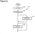
- Figure 6 is a syntax diagram for the slice layer 600, which includes a slice header 610 followed by data for the macroblock layer 520.
- the elements that make up the slice header 610 include a slice address (SLICE_ADDR) element 620, and a picture header present flag (PIC_HEADER_FLAG) element 630, as also shown in the following table 1.
- SLICE_ADDR slice address
- PIC_HEADER_FLAG picture header present flag
- the slice address element 620 is a fixed-length 9-bit syntax element.
- the row address of the first macroblock row in the slice is binary encoded in this syntax element.
- the range of this syntax element is from 1 to 511, where the maximum picture size of 8192 corresponds to a maximum of 512 macroblock rows.
- an Independently Decodable Unit (IDU) of compressed video data begins with an identifier called a Start Code (SC).
- An IDU could refer to a single picture, or a slice (i.e., group of macroblocks in a picture), or a group of pictures (GOP), or a sequence header.
- the start code is a sequence of four bytes, which consists of an unique three-byte Start Code Prefix (SCP), and an one byte Start Code Suffix (SCS).
- SCP is the unique sequence of three bytes (0x000001).
- SCS is used to identify the type of IDU that follows the start code. For example, the suffix of the start code before a picture is different from the suffix of the start code before a slice. Start codes are always byte-aligned.
- An Encapsulation Mechanism is described to prevent emulation of the start code prefix in the bitstream.
- the compressed data before encapsulation is called Raw Independently Decodable Unit (RIDU), while Encapsulated IDU (EIDU) refers to the data after encapsulation.
- RIDU Raw Independently Decodable Unit
- EIDU Encapsulated IDU
- Section E.2 specifies detection of start codes and EIDUs at the decoder.
- Section E.3 deals with extraction of an RIDU from an EIDU.
- Section E.4 specifies start code suffixes for various IDU types.
- Step 1 A trailing '1' bit is added to the end of the RIDU.
- the EM now appends between 0 and 7 bits onto the end of the IDU such that the IDU ends in a byte-aligned location.
- the value of these "stuffing" bits is '0'.
- the IDU is represented in an integer number of bytes, in which the last byte of the IDU cannot be a zero-valued byte..
- the resulting string of bytes is called the payload bytes of the IDU.
- Step 2 The three-byte start code prefix (0x000001), and the appropriate start code suffix that identifies the IDU type are placed at the beginning of the EIDU.
- Step 3 The remainder of the EIDU is formed by processing the payload bytes of the IDU through the following emulation prevention process.
- the emulation of start code prefixes in the IDU is eliminated via byte-stuffing.
- the emulation prevention process is equivalent to the following operation:
- Step 3 The three-byte start code prefix (0x000001), and the appropriate start code suffix that identifies the IDU type are attached to the beginning of the IDU.
- the resulting payload is an encapsulated IDU.
- the encoder is also allowed to insert any number of zero-valued stuffing bytes after the end of an EIDU. Equivalently, any number of zero-valued stuffing bytes can be inserted before a start code prefix.
- the start code is structured such that it can be detected by a decoder even if in the presence of these zero-valued stuffing bytes.
- the encoder may use this feature to insert extra zero-valued stuffing bytes bytes as desired, which can enable the decoder to quickly recover the location of the start- codes even if it has lost track of the intended alignment of the bitstream to byte boundaries.
- Zero-Valued Stuffing bytes prior to start codes, or at the end of an EIDU are not processed through the encapsulation mechanism - only RIDU data requires such processing.
- the detection of an EIDU starts with the search for the start code prefix.
- start code detection is conducted as follows.
- start-code prefix detection and byte-alignment detection are conducted as follows. Whenever a string of three or more bytes of value 0x00 is found, followed by any non-zero byte is found, a start code prefix detection is declared and byte alignment is understood to be recovered such that the first nonzero bit in the non-zero byte is the last bit of a byte-aligned start code.
- Step 1 The start-code suffix is used to identify the type of IDU.
- Step 2 The first step is to remove the zero-valued stuffing bytes at the end of EIDU. After this step, the last byte of the IDU must have a non-zero value.
- Step 3 The bytes used for emulation prevention are detected and removed. The process is as follows: Whenever a string of two bytes of value 0x00 is followed by a byte equal to 0x03, the byte equal to 0x03 is understood to be an emulation prevention byte and is discarded.
- Table 3 Decoder Removal of Emulation Prevention Data Pattern to Replace Replacement Pattern 0x00, 0x00, 0x03, 0x00 0x00, 0x00, 0x00, 0x00, 0x00, 0x03, 0x01 0x00, 0x00, 0x00, 0x00, 0x03, 0x02 0x00, 0x00, 0x00, 0x00, 0x03, 0x03 0x00, 0x00, 0x00, 0x00, 0x00, 0x00, 0x00, 0x00, 0x00, 0x00, 0x00, 0x00, 0x00, 0x00, 0x00, 0x00, 0x00, 0x00, 0x00, 0x00, 0x00, 0x00, 0x00, 0x00, 0x00, 0x
- Step 4 In the last-byte of the IDU, the last non-zero bit is identified, and that non-zero bit, and all the "zero" bits that follow are discarded. The result is a raw IDU.
- Start code Suffixes for Various IDU Types Start-code Suffix IDU Type 0x00 SMPTE Reserved 0x01-0x09 SMPTE Reserved 0x0A End-of-Sequence 0x0B Slice 0x0C Field 0x0D Frame 0x0E Entry-point Header 0x0F Sequence Header 0x10-0x1A SMPTE Reserved 0x1B Slice Level User Data 0x1C Field Level User Data 0x1D Frame Level User Data 0x1E Entry-point Level User Data 0x1F Sequence Level User Data 0x20-0x7F SMPTE Reserved 0x80-0xFF Forbidden
- the SequenceHeader suffix is sent to identify IDUs which carry a sequence header 410 ( Figure 4 ).
- the Entry-point Header suffix is sent to identify IDUs which carry an entry-point header.
- the Picture suffix is sent to identify IDUs which contains the picture 320 ( Figure 3 , and the picture header 510 ( Figure 5 ).
- the Field suffix is sent to identify IDUs which contain the second field of a picture that is coded as two separate fields.
- the Slice suffix is sent to identify IDUs which carry slices 320 ( Figure 3 ), and the slice header 610 ( Figure 6 ).
- the Sequence, Entry-point, Frame, Field, and Slice Level User data suffixes are used to transmit any user defined data associated with the Sequence, Entry-point, Frame, Field, and Slice respectively.
- End-of-sequence is an optional suffix which indicates that the current sequence has ended, and no further data will be transmitted for this sequence. Note that the transmission of an "end-of-sequence" may be present, but the end of a sequence shall be inferred from the header of the next sequence.
- the illustrated slice layer 320 ( Figure 3 ) also achieves independent decodability, and independent reconstruction. This enables the slice to be reconstructed error-free at the decoder irrespective of transmission errors or packet loss in other regions of the picture 310 ( Figure 3 ).
- the content of a slice layer 320 is decoded independently of the picture content in other slices or regions of the picture.
- the encoder 100 and decoder 200 reset the motion vector predictors, predictors for AC and DC coefficients, and the predictors for quantization parameters.
- the first row of macroblocks in the slice is treated as if it were the first row of macroblocks in the picture. This helps to ensure that there is no inter-slice dependency in predictors.
- macroblock level information that is otherwise coded (e.g., using bitplane coding) at the picture layer (such as motion vector mode, and flags for ac prediction) are carried locally with other macroblock level information such as transform coefficients. This allows each slice to be decoded independently (i.e., without reliance on data decoded from other slices of the picture).
- the process of reconstruction of a slice is performed independently from reconstruction of any other slice (e.g., adjacent slices) in a picture. Accordingly, any processes (such as inloop deblocking or overlap filtering, described below) that would otherwise be applied across boundaries between adjacent slices in a picture are disallowed.
- the top and bottom macroblock rows of each slice are treated as if they are the top and bottom macroblock rows of the picture in such boundary processes.
- Overlapped transforms are modified block based transforms that exchange information across the block boundary. With a well designed overlapped transform, blocking artifacts can be minimized.
- the illustrated video codec simulates an overlapped transform by coupling an 8x8 block transform with a filtering operation (referred to as overlap smoothing). Edges of an 8x8 block that separate two intra blocks are smoothed - in effect an overlapped transform is implemented at this interface. Except, overlap smoothing is not performed across slice boundaries in any case.
- a filtering operation may be conditionally performed across edges of two neighboring Intra blocks, for both the luminance and chrominance channels.
- This filtering operation (referred to as overlap smoothing ) is performed subsequent to decoding the frame, and prior to in-loop deblocking.
- overlap smoothing may be done after the relevant macroblock slices are decoded as this is functionally equivalent to smoothing after decoding the entire frame.
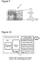
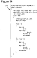
- Figure 7 shows an example of overlap smoothing performed on a portion of a P frame with I blocks. This could be either the luminance or chrominance channel. I blocks are gray (or crosshatched) and P blocks are white. In this illustration, the edge interface over which overlap smoothing is applied is marked with a crosshatch pattern. Overlap smoothing is applied to two pixels on either side of the separating boundary. The right bottom area of frame is shown here as an example. Pixels occupy individual cells and blocks are separated by heavy lines. The dark circle marks the 2x2 pixel corner subblock that is filtered in both directions.
- the lower inset in Figure 7 shows four labeled pixels, a0 and a1 are to the left and b1, b0 to the right of the vertical block edge.
- the upper inset shows pixels marked p0, p1, q1 and q0 straddling a horizontal edge.
- the next section describes the filter applied to these four pixel locations.
- Overlap smoothing is carried out on the unclamped 16 bit reconstruction. This is necessary because the forward process associated with overlap smoothing may result in range expansion beyond the permissible 8 bit range for pixel values. The result of overlap smoothing is clamped down to 8 bits, in line with the remainder of the pixels not touched by overlap smoothing.
- the original pixels being filtered are (x0, x1, x2, x3).
- r0 and r1 are rounding parameters, which take on alternating values of 3 and 4 to ensure statistically unbiased rounding.
- the original values are filtered by the matrix with entries that are clearly easy to implement. These values, after adding the rounding factors, are bit shifted by three bits to give the filtered output (y0, y1, y2, y3).
- Filtering is defined as an in-place 16 bit operation - thus the original pixels are overwritten after smoothing.
- the pixels (a0, a1, b1, b0) correspond to (x0, x1, x2, x3), which in turn get filtered to (y0, y1, y2, y3).
- the correspondence is with (p0, p1, q1, q0) respectively.
- Pixels in the 2x2 corner are filtered in both directions.
- the order of filtering determines their final values, and therefore it is important to maintain the order - vertical edge filtering followed by horizontal edge filtering - for bit exactness.
- clamping is to be performed subsequent to the two directional filtering stages, on all pixels that are filtered.
- the filtering process operates on the pixels that border neighboring blocks.
- the block boundaries can occur at every 4 th , 8 th , 12 th , etc pixel row or column depending on whether an 8x8, 8x4 or 4x8 Inverse Transform is used.
- For I pictures filtering occurs at every 8 th , 16 th , 24 th , etc pixel row and column.
- FIGS. 8 and 9 show the pixels that are filtered along the horizontal and vertical border regions of an I-picture frame.
- the figures show the upper left corner of a component (luma, Cr or Cb) plane.
- the crosses represent pixels and the circled crosses represent the pixels that are filtered.
- the top horizontal line and first vertical line of a picture or slice are not filtered.
- the bottom horizontal line and last vertical line of a picture or slice are also not filtered.
- the following lines are filtered:
- the order in which the pixels are filtered is important. All the horizontal boundary lines in the frame are filtered first followed by the vertical boundary lines.
- blocks may be Intra or Inter-coded.
- Intra-coded blocks always use an 8x8 Transform to transform the samples and the 8x8 block boundaries are always filtered.
- Inter-coded blocks may use an 8x8, 8x4, 4x8 or 4x4 Inverse Transform to construct the samples that represent the residual error.
- the boundary between the current and neighboring blocks may or may not be filtered. In any case, the boundary edges of a picture or slice are not filtered.
- This section describes the filtering operation that is performed on the block boundary pixels in I and P frames, as discussed above.
- the filtering operation is performed on segments of four pixels.
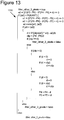
- the eight pixels are divided into two 4-pixel segments 1100 as shown in Figure 12 .
- the third pixel pair is filtered first as indicated by the X's. The result of this filter operation determines whether the other three pixels in the segment are also filtered, as described below.
- Figure 10 shows the pixels 1200 that are used in the filtering operation performed on the 3 rd pixel pair.
- Pixels P4 and P5 are the pixel pairs that may be changed in the filter operation.
- the pseudocode 1300 of Figure 13 shows the filtering operation performed on the 3 rd pixel pair in each segment.
- This section used the vertical boundary for example purposes.
- the same operation is used for filtering the horizontal boundary pixels.
- the above described implementations of the slice layer coding can be performed on any of a variety of devices in which image and video signal processing is performed, including among other examples, computers; image and video recording, transmission and receiving equipment; portable video players; video conferencing; Web video streaming applications; and etc.
- the image and video coding techniques can be implemented in hardware circuitry (e.g., in circuitry of an ASIC, FPGA, etc.), as well as in image and video processing software executing within a computer or other computing environment (whether executed on the central processing unit (CPU), or dedicated graphics processor, video card or like), such as shown in Figure 10 .
- FIG 10 illustrates a generalized example of a suitable computing environment (1000) in which the described slice layer coding may be implemented.
- the computing environment (1000) is not intended to suggest any limitation as to scope of use or functionality of the invention, as the present invention may be implemented in diverse general-purpose or special-purpose computing environments.
- the computing environment (1000) includes at least one processing unit (1010) and memory (1020).
- the processing unit (1010) executes computer-executable instructions and may be a real or a virtual processor. In a multi-processing system, multiple processing units execute computer-executable instructions to increase processing power.
- the memory (1020) may be volatile memory (e.g., registers, cache, RAM), non-volatile memory (e.g., ROM, EEPROM, flash memory, etc.), or some combination of the two.
- the memory (1020) stores software (1080) implementing the described slice layer coding.
- a computing environment may have additional features.
- the computing environment (1000) includes storage (1040), one or more input devices (1050), one or more output devices (1060), and one or more communication connections (1070).
- An interconnection mechanism such as a bus, controller, or network interconnects the components of the computing environment (1000).
- operating system software provides an operating environment for other software executing in the computing environment (1000), and coordinates activities of the components of the computing environment (1000).
- the storage (1040) may be removable or non-removable, and includes magnetic disks, magnetic tapes or cassettes, CD-ROMs, CD-RWs, DVDs, or any other medium which can be used to store information and which can be accessed within the computing environment (1000).
- the storage (1040) stores instructions for the software (1080) implementing the audio encoder that performs the slice layer coding.
- the input device(s) (1050) may be a touch input device such as a keyboard, mouse, pen, or trackball, a voice input device, a scanning device, or another device that provides input to the computing environment (1000).
- the input device(s) (1050) may be a sound card or similar device that accepts audio input in analog or digital form, or a CD-ROM reader that provides audio samples to the computing environment.
- the output device(s) (1060) maybe a display, printer, speaker, CD-writer, or another device that provides output from the computing environment (1000).
- the communication connection(s) (1070) enable communication over a communication medium to another computing entity.
- the communication medium conveys information such as computer-executable instructions, compressed audio or video information, or other data in a modulated data signal.
- a modulated data signal is a signal that has one or more of its characteristics set or changed in such a manner as to encode information in the signal.
- communication media include wired or wireless techniques implemented with an electrical, optical, RF, infrared, acoustic, or other carrier.
- Computer-readable media are any available media that can be accessed within a computing environment.
- Computer-readable media include memory (1020), storage (1040), communication media, and combinations of any of the above.
- the slice layer coding herein can be described in the general context of computer-executable instructions, such as those included in program modules, being executed in a computing environment on a target real or virtual processor.
- program modules include routines, programs, libraries, objects, classes, components, data structures, etc. that perform particular tasks or implement particular abstract data types.
- the functionality of the program modules may be combined or split between program modules as desired in various embodiments.
- Computer-executable instructions for program modules may be executed within a local or distributed computing environment.
Landscapes
- Engineering & Computer Science (AREA)
- Multimedia (AREA)
- Signal Processing (AREA)
- Compression Or Coding Systems Of Tv Signals (AREA)
- Compression, Expansion, Code Conversion, And Decoders (AREA)
Claims (11)
- Verfahren zum Decodieren von Video und Bildern, umfassend:
Decodieren eines Bildes aus einem codierten Bitstrom mit einer Syntaxhierarchie, umfassend mindestens eine Bildschicht (310,500), eine unabhängig decodierbare Scheibe (320), die ein oder mehrere zusammenhängende Reihen von Makroblöcken des Bildes enthält, und eine Makroblockschicht (340, 520), wobei eine Codierungssyntax (600) der unabhängig decodierbaren Scheibe einen Startcode beinhaltet, der aus einem Start-code-Präfix, SCP, besteht, wobei es sich um eine eindeutige Sequenz aus drei Bytes handelt, und einem Ein-Byte-Startcode-Suffix, SCS, das dazu dient, eine Scheibe zu identifizieren, wobei auf den Startcode ein Scheiben-Header (610) folgt, der eine Adresse (620) der Scheibe und eine Anzeige (630) signalisiert, ob die Bild-Headerinformationen (510) in dieser Scheibe wiederholt werden, wobei auf den Scheiben-Header Nutzlastdaten für die Makroblockschicht folgen, wobei eine Emulation des SCP durch einen Kapselungsmechanismus verhindert wird, gemäß dem jede Kette innerhalb der Nutzlast aus drei aufeinanderfolgenden Bytes ähnlich den drei Bytes des SCP durch eine ähnliche Kette ersetzt wird, in die ein zusätzliches Byte mit festem Wert eingesetzt wurde, wobei das Decodieren des Bildes umfasst:Decodieren der signalisierten Anzeige, ob die Bild-Headerinformationen in der Scheibe wiederholt werden;wenn angezeigt wird, dass die Bild-Headerinformationen wiederholt werden, Decodieren der Bild-Headerinformationen;Decodieren der signalisierten Adresse;Rekonstruieren der Scheibe an einer Position in dem Bild, die von der signalisierten Adresse angezeigt wird; undDurchführen von Überlappungsglättung (700) an zumindest einigen Blockrändern innerhalb der Scheibe, ausgenommen an Grenzrändern der Scheibe, wobei die Überlappungsglättung Filtervorgänge beinhaltet, die an eine blockbasierte Transformation gekoppelt sind, um eine überlappte Transformation zu simulieren. - Verfahren nach Anspruch 1, wobei die Codierungssyntax die Adresse als einen Makroblock-Zeilenindex der Scheibe signalisiert.
- Verfahren nach Anspruch 1, wobei die Codierungssyntax die Anzeige, ob die Bild-Headerinformationen in der Scheibe wiederholt werden, als ein einzelnes Bitflag signalisiert.
- Verfahren nach Anspruch 1, wobei das Decodieren des Bildes des Weiteren umfasst:
Durchführen von Entblockierungsfilterung an mindestens einigen Blockrändern innerhalb der Scheibe, ausgenommen an Grenzrändern der Scheibe. - Verfahren nach Anspruch 1, wobei das Decodieren des Bildes des Weiteren umfasst:
Zurücksetzen der Vorhersagecodierungsparameter bei Beginn der Decodierung der Scheibe. - Verfahren zum Codieren eines Bildes oder Videos, umfassend:
Codieren eines Bildes in mindestens einer unabhängig decodierbaren Scheibe (320), die eine oder mehrere zusammenhängende Zeilen aus Makroblöcken des Bildes enthält, wobei das Codieren des Bildes umfasst:zu Beginn der Codierung von Bildinhaltinformationen einer jeweiligen Scheibe der mindestens einen unabhängig decodierbaren Scheibe, Zurücksetzen der Vorhersagecodierungsparameter;Signalisieren eines Beginns einer jeweiligen Scheibe der mindestens einen unabhängig decodierbaren Scheibe vom Codierer zum Decodierer unter Verwendung eines eindeutigen Startcode-Musters, das aus einem Startcode-Präfix, SCP, besteht, bei welchem es sich um eine eindeutige Sequenz aus drei Bytes handelt, und einem Ein-Byte-Startcode-Suffix, SCS, das zum Identifizieren einer Scheibe dient, wobei auf den Startcode ein Scheiben-Header (610) folgt, auf den Scheiben-Header Nutzlastdaten für eine Makroblockschicht (340, 520) folgen, wobei eine Emulation des SCP durch einen Kapselungsmechanismus verhindert wird, gemäß dem jede Kette innerhalb der Nutzlast aus drei aufeinanderfolgenden Bytes ähnlich den drei Bytes des SCP durch eine ähnliche Kette ersetzt wird, in die ein zusätzliches Byte mit festem Wert eingesetzt wurde;Signalisieren, in dem Scheiben-Header, einer Position einer jeweiligen Scheibe der mindestens einen unabhängig decodierbaren Scheibe vom Codierer zum Decodierer unter Verwendung eines Adressparameters (620) der sich auf eine Anfangs-Makroblockposition der jeweiligen Scheibe in dem Bild bezieht;Signalisieren, in dem Scheiben-Header, einer Anzeige (630) darüber, ob Bild-Headerinformationen (510) in einer entsprechenden Scheibe aus der mindestens einen unabhängig decodierbaren Scheibe wiederholt werden, vom Codierer zum Decodierer; undRekonstruieren von Bildinhalt der jeweiligen Scheibe unabhängig von Bildinhalt außerhalb der jeweiligen Scheibe, wobei das unabhängige Rekonstruieren das Durchführen von Überlappungsglättung (700) von Blockrändern innerhalb des Bildinhalts der jeweiligen Scheibe umfasst, ausgenommen an Grenzrändern der jeweiligen Scheibe, wobei die Überlappungsglättung Filtervorgänge beinhaltet, die an eine blockbasierte Transformation gekoppelt sind, um eine überlappte Transformation zu simulieren. - Verfahren nach Anspruch 6, wobei der Adressparameter ein Anfangs-Makroblock-Zeilenindex der Scheibe ist.
- Verfahren nach Anspruch 6, wobei die Anzeige ein Flag-Wert ist.
- Verfahren nach Anspruch 6, wobei das unabhängige Rekonstruieren des Weiteren umfasst:
Durchführen von Entblockierung von Blockrändern innerhalb des Bildinhalts der jeweiligen Scheibe, ausgenommen an Grenzrändern der jeweiligen Scheibe. - Mindestens ein Medium, das ein computerlesbares Programm enthält, auf dem sich das Softwaremodul befindet, das durch eine Verarbeitungseinheit ausführbar ist, um ein Verfahren nach einem der Ansprüche 1 bis 5 durchzuführen.
- Mindestens ein Medium, das ein computerlesbares Programm enthält, auf dem sich das Softwaremodul befindet, das durch eine Verarbeitungseinheit ausführbar ist, um ein Verfahren nach einem der Ansprüche 6 bis 9 durchzuführen.
Applications Claiming Priority (3)
| Application Number | Priority Date | Filing Date | Title |
|---|---|---|---|
| US50108103P | 2003-09-07 | 2003-09-07 | |
| US10/933,960 US7162093B2 (en) | 2003-09-07 | 2004-09-03 | Slice-layer in video codec |
| PCT/US2004/029033 WO2005027495A2 (en) | 2003-09-07 | 2004-09-03 | Slice layer in video codec |
Publications (3)
| Publication Number | Publication Date |
|---|---|
| EP1656793A2 EP1656793A2 (de) | 2006-05-17 |
| EP1656793A4 EP1656793A4 (de) | 2011-09-28 |
| EP1656793B1 true EP1656793B1 (de) | 2019-11-27 |
Family
ID=34228806
Family Applications (1)
| Application Number | Title | Priority Date | Filing Date |
|---|---|---|---|
| EP04783323.1A Expired - Lifetime EP1656793B1 (de) | 2003-09-07 | 2004-09-03 | Schichtlage in video codec |
Country Status (7)
| Country | Link |
|---|---|
| US (1) | US7162093B2 (de) |
| EP (1) | EP1656793B1 (de) |
| JP (2) | JP5280003B2 (de) |
| KR (1) | KR101103867B1 (de) |
| ES (1) | ES2767933T3 (de) |
| MX (1) | MXPA06002495A (de) |
| WO (1) | WO2005027495A2 (de) |
Families Citing this family (77)
| Publication number | Priority date | Publication date | Assignee | Title |
|---|---|---|---|---|
| CN101448162B (zh) * | 2001-12-17 | 2013-01-02 | 微软公司 | 处理视频图像的方法 |
| JP2005033336A (ja) * | 2003-07-08 | 2005-02-03 | Ntt Docomo Inc | 動画像符号化装置、動画像符号化方法及び動画像符号化プログラム |
| US10554985B2 (en) | 2003-07-18 | 2020-02-04 | Microsoft Technology Licensing, Llc | DC coefficient signaling at small quantization step sizes |
| US7801383B2 (en) * | 2004-05-15 | 2010-09-21 | Microsoft Corporation | Embedded scalar quantizers with arbitrary dead-zone ratios |
| US9208824B2 (en) * | 2004-05-18 | 2015-12-08 | Broadcom Corporation | Index table generation in PVR applications for AVC video streams |
| US7590059B2 (en) * | 2004-05-21 | 2009-09-15 | Broadcom Corp. | Multistandard video decoder |
| US20060013315A1 (en) * | 2004-07-19 | 2006-01-19 | Samsung Electronics Co., Ltd. | Filtering method, apparatus, and medium used in audio-video codec |
| KR100587698B1 (ko) * | 2004-10-22 | 2006-06-08 | 주식회사 휴맥스 | 선택적 예측 부호화/복호화 방법 및 장치 |
| KR100652689B1 (ko) * | 2004-10-26 | 2006-12-07 | 엘지전자 주식회사 | 휴대단말기에서의 컨텐츠의 사이즈 분석 방법 |
| US8576924B2 (en) * | 2005-01-25 | 2013-11-05 | Advanced Micro Devices, Inc. | Piecewise processing of overlap smoothing and in-loop deblocking |
| US7792385B2 (en) * | 2005-01-25 | 2010-09-07 | Globalfoundries Inc. | Scratch pad for storing intermediate loop filter data |
| US7953161B2 (en) * | 2005-04-27 | 2011-05-31 | Broadcom Corporation | System and method for overlap transforming and deblocking |
| KR101170799B1 (ko) | 2005-05-21 | 2012-08-02 | 삼성전자주식회사 | 영상 압축 방법 및 그 장치와 영상 복원 방법 및 그 장치 |
| US8422546B2 (en) | 2005-05-25 | 2013-04-16 | Microsoft Corporation | Adaptive video encoding using a perceptual model |
| US7965773B1 (en) | 2005-06-30 | 2011-06-21 | Advanced Micro Devices, Inc. | Macroblock cache |
| FR2894740A1 (fr) * | 2005-12-12 | 2007-06-15 | Thomson Licensing Sa | Dispositif de codage, procede de codage, systeme de decodage procede de decodage de donnees video |
| US20070147496A1 (en) * | 2005-12-23 | 2007-06-28 | Bhaskar Sherigar | Hardware implementation of programmable controls for inverse quantizing with a plurality of standards |
| US7636497B1 (en) | 2005-12-27 | 2009-12-22 | Advanced Micro Devices, Inc. | Video rotation in a media acceleration engine |
| JP5266202B2 (ja) * | 2006-03-28 | 2013-08-21 | サムスン エレクトロニクス カンパニー リミテッド | 画像符号化/復号化方法及び装置 |
| US7974340B2 (en) * | 2006-04-07 | 2011-07-05 | Microsoft Corporation | Adaptive B-picture quantization control |
| US7995649B2 (en) * | 2006-04-07 | 2011-08-09 | Microsoft Corporation | Quantization adjustment based on texture level |
| US8503536B2 (en) * | 2006-04-07 | 2013-08-06 | Microsoft Corporation | Quantization adjustments for DC shift artifacts |
| US8130828B2 (en) * | 2006-04-07 | 2012-03-06 | Microsoft Corporation | Adjusting quantization to preserve non-zero AC coefficients |
| US8059721B2 (en) * | 2006-04-07 | 2011-11-15 | Microsoft Corporation | Estimating sample-domain distortion in the transform domain with rounding compensation |
| JP5389205B2 (ja) * | 2006-04-27 | 2014-01-15 | キヤノン株式会社 | 画像符号化装置、画像符号化方法、プログラム及び記憶媒体 |
| US8711925B2 (en) * | 2006-05-05 | 2014-04-29 | Microsoft Corporation | Flexible quantization |
| JP4229149B2 (ja) * | 2006-07-13 | 2009-02-25 | ソニー株式会社 | ビデオ信号処理装置およびビデオ信号処理方法、ビデオ信号符号化装置およびビデオ信号符号化方法、並びにプログラム |
| US8428144B2 (en) | 2006-09-07 | 2013-04-23 | Lg Electronics Inc. | Method and apparatus for decoding/encoding of a video signal |
| JP2009540666A (ja) | 2006-11-09 | 2009-11-19 | エルジー エレクトロニクス インコーポレイティド | ビデオ信号のデコーディング/エンコーディング方法及び装置 |
| WO2008060125A1 (en) | 2006-11-17 | 2008-05-22 | Lg Electronics Inc. | Method and apparatus for decoding/encoding a video signal |
| US8238424B2 (en) * | 2007-02-09 | 2012-08-07 | Microsoft Corporation | Complexity-based adaptive preprocessing for multiple-pass video compression |
| JP4847890B2 (ja) * | 2007-02-16 | 2011-12-28 | パナソニック株式会社 | 符号化方式変換装置 |
| US8498335B2 (en) * | 2007-03-26 | 2013-07-30 | Microsoft Corporation | Adaptive deadzone size adjustment in quantization |
| KR101086434B1 (ko) * | 2007-03-28 | 2011-11-25 | 삼성전자주식회사 | 비디오 데이터 디스플레이 방법 및 장치 |
| US8243797B2 (en) | 2007-03-30 | 2012-08-14 | Microsoft Corporation | Regions of interest for quality adjustments |
| US8442337B2 (en) * | 2007-04-18 | 2013-05-14 | Microsoft Corporation | Encoding adjustments for animation content |
| US8331438B2 (en) * | 2007-06-05 | 2012-12-11 | Microsoft Corporation | Adaptive selection of picture-level quantization parameters for predicted video pictures |
| CN101389021B (zh) * | 2007-09-14 | 2010-12-22 | 华为技术有限公司 | 视频编解码方法及装置 |
| WO2009033432A1 (fr) * | 2007-09-14 | 2009-03-19 | Huawei Technologies Co., Ltd. | Procédé et appareil pour codage et décodage vidéo |
| US8938009B2 (en) * | 2007-10-12 | 2015-01-20 | Qualcomm Incorporated | Layered encoded bitstream structure |
| BRPI0818444A2 (pt) * | 2007-10-12 | 2016-10-11 | Qualcomm Inc | codificação adaptativa de informação de cabeçalho de bloco de vídeo |
| US8542748B2 (en) | 2008-03-28 | 2013-09-24 | Sharp Laboratories Of America, Inc. | Methods and systems for parallel video encoding and decoding |
| US8189933B2 (en) * | 2008-03-31 | 2012-05-29 | Microsoft Corporation | Classifying and controlling encoding quality for textured, dark smooth and smooth video content |
| US8897359B2 (en) * | 2008-06-03 | 2014-11-25 | Microsoft Corporation | Adaptive quantization for enhancement layer video coding |
| US8718135B2 (en) * | 2008-09-19 | 2014-05-06 | The Hong Kong University Of Science And Technology | Method and system for transcoding based robust streaming of compressed video |
| EP2457376A4 (de) * | 2009-07-20 | 2013-01-30 | Samsung Electronics Co Ltd | Verfahren und vorrichtung zum codieren und decodieren von farbkanälen bei der geschichteten videocodierung und -decodierung |
| KR101474756B1 (ko) | 2009-08-13 | 2014-12-19 | 삼성전자주식회사 | 큰 크기의 변환 단위를 이용한 영상 부호화, 복호화 방법 및 장치 |
| US8433978B2 (en) * | 2009-10-29 | 2013-04-30 | Cleversafe, Inc. | Data distribution utilizing unique read parameters in a dispersed storage system |
| US8352831B2 (en) * | 2009-12-29 | 2013-01-08 | Cleversafe, Inc. | Digital content distribution utilizing dispersed storage |
| TWI442778B (zh) | 2010-02-05 | 2014-06-21 | Acer Inc | 視訊解碼裝置 |
| US20110213932A1 (en) * | 2010-02-22 | 2011-09-01 | Takuma Chiba | Decoding apparatus and decoding method |
| CN102550029B (zh) * | 2010-07-30 | 2015-10-07 | 松下电器产业株式会社 | 图像解码装置、图像解码方法、图像编码装置以及图像编码方法 |
| US9525884B2 (en) | 2010-11-02 | 2016-12-20 | Hfi Innovation Inc. | Method and apparatus of slice boundary filtering for high efficiency video coding |
| US9060174B2 (en) * | 2010-12-28 | 2015-06-16 | Fish Dive, Inc. | Method and system for selectively breaking prediction in video coding |
| EP2675169B1 (de) | 2011-02-09 | 2019-06-26 | LG Electronics Inc. | Verfahren zur kodierung und dekodierung von bildern mit einem zeitlichen bewegungsvektorprädiktor und vorrichtung damit |
| US8848804B2 (en) * | 2011-03-04 | 2014-09-30 | Vixs Systems, Inc | Video decoder with slice dependency decoding and methods for use therewith |
| GB2488830B (en) * | 2011-03-10 | 2015-07-29 | Canon Kk | Method and device for encoding image data and method and device for decoding image data |
| GB2488829A (en) * | 2011-03-10 | 2012-09-12 | Canon Kk | Encoding and decoding image data |
| US9008180B2 (en) | 2011-04-21 | 2015-04-14 | Intellectual Discovery Co., Ltd. | Method and apparatus for encoding/decoding images using a prediction method adopting in-loop filtering |
| GB2493209B (en) * | 2011-07-29 | 2016-02-17 | Canon Kk | Method and device for parallel decoding of scalable bitstream elements |
| ES2835801T3 (es) * | 2011-09-09 | 2021-06-23 | Sun Patent Trust | Decisiones de filtro de desbloqueo de baja complejidad |
| US9237352B2 (en) | 2011-10-05 | 2016-01-12 | Texas Instruments Incorporated | Methods and systems for encoding pictures associated with video data |
| GB2551088B (en) | 2011-10-17 | 2018-09-19 | Kt Corp | Method and apparatus for encoding/decoding image |
| US20140198844A1 (en) * | 2011-10-24 | 2014-07-17 | Mediatek Inc. | Method and apparatus for non-cross-tile loop filtering |
| MX2013009066A (es) * | 2011-12-15 | 2013-10-01 | Panasonic Corp | Metodo de codificacion de imagenes, metodo de decodificacion de imagenes, aparato de codificacion de imagenes, aparato de decodificacion de imagenes y aparato de codificacion y decodificacion de imagenes. |
| US9538200B2 (en) * | 2012-01-19 | 2017-01-03 | Qualcomm Incorporated | Signaling of deblocking filter parameters in video coding |
| CN102752058B (zh) * | 2012-06-16 | 2013-10-16 | 天地融科技股份有限公司 | 音频数据传输系统、音频数据传输装置及电子签名工具 |
| KR102259792B1 (ko) | 2012-07-02 | 2021-06-02 | 엘지전자 주식회사 | 영상 정보 코딩 방법 및 이를 이용하는 장치 |
| US20140153635A1 (en) * | 2012-12-05 | 2014-06-05 | Nvidia Corporation | Method, computer program product, and system for multi-threaded video encoding |
| US9076206B2 (en) * | 2013-03-12 | 2015-07-07 | Uurmi Systems Private Limited | Methods and systems for correcting distortions in multimedia content |
| US9813730B2 (en) * | 2013-12-06 | 2017-11-07 | Mediatek Inc. | Method and apparatus for fine-grained motion boundary processing |
| EP3900360A4 (de) * | 2018-12-20 | 2022-03-16 | Telefonaktiebolaget Lm Ericsson (Publ) | Verfahren zur codierung und/oder decodierung von video mit syntaxanzeiger und bildheader |
| CN111416976B (zh) * | 2019-01-08 | 2023-12-08 | 浙江大学 | 视频解码方法、视频编码方法、装置、设备及存储介质 |
| PT3957071T (pt) | 2019-05-03 | 2024-06-07 | Huawei Tech Co Ltd | Processamento paralelo de frente de onda para mosaico, tijolo e setor |
| RU2758901C1 (ru) | 2019-06-24 | 2021-11-02 | Телефонактиеболагет Лм Эрикссон (Пабл) | Передача в служебных сигналах информации значений параметров в наборе параметров, чтобы уменьшать объем данных, содержащихся в кодированном потоке битов видео |
| CN120358358A (zh) * | 2019-08-22 | 2025-07-22 | 夏普株式会社 | 用于在视频编码中发送信号通知图片信息的系统和方法 |
| GB2592957A (en) | 2020-03-11 | 2021-09-15 | Canon Kk | High level syntax for video coding and decoding |
Family Cites Families (17)
| Publication number | Priority date | Publication date | Assignee | Title |
|---|---|---|---|---|
| JP2674059B2 (ja) | 1988-02-09 | 1997-11-05 | キヤノン株式会社 | カラー画像データ伝送方法 |
| JP2794899B2 (ja) | 1990-05-08 | 1998-09-10 | 松下電器産業株式会社 | 符号化装置 |
| US5168356A (en) | 1991-02-27 | 1992-12-01 | General Electric Company | Apparatus for segmenting encoded video signal for transmission |
| US6226327B1 (en) * | 1992-06-29 | 2001-05-01 | Sony Corporation | Video coding method and apparatus which select between frame-based and field-based predictive modes |
| JP2856300B2 (ja) * | 1993-02-19 | 1999-02-10 | 富士ゼロックス株式会社 | 画像符号化装置および復号装置 |
| KR0170937B1 (ko) * | 1994-12-14 | 1999-03-20 | 배순훈 | 영상 데이타 부호화 장치 |
| US6026182A (en) | 1995-10-05 | 2000-02-15 | Microsoft Corporation | Feature segmentation |
| JPH1174868A (ja) * | 1996-09-02 | 1999-03-16 | Toshiba Corp | 情報伝送方法およびその方法が適用される情報伝送システムにおける符号化装置/復号化装置、並びに符号化・多重化装置/復号化・逆多重化装置 |
| US5974184A (en) * | 1997-03-07 | 1999-10-26 | General Instrument Corporation | Intra-macroblock DC and AC coefficient prediction for interlaced digital video |
| JP2000209580A (ja) * | 1999-01-13 | 2000-07-28 | Canon Inc | 画像処理装置およびその方法 |
| JP2001016594A (ja) * | 1999-06-29 | 2001-01-19 | Hitachi Ltd | 動画像の動き補償方法 |
| GB2352350B (en) * | 1999-07-19 | 2003-11-05 | Nokia Mobile Phones Ltd | Video coding |
| JP2003209387A (ja) * | 2001-11-06 | 2003-07-25 | Hitachi Metals Ltd | 電磁波吸収体 |
| US7263125B2 (en) * | 2002-04-23 | 2007-08-28 | Nokia Corporation | Method and device for indicating quantizer parameters in a video coding system |
| JP3807342B2 (ja) * | 2002-04-25 | 2006-08-09 | 三菱電機株式会社 | デジタル信号符号化装置、デジタル信号復号装置、デジタル信号算術符号化方法、およびデジタル信号算術復号方法 |
| US7724818B2 (en) * | 2003-04-30 | 2010-05-25 | Nokia Corporation | Method for coding sequences of pictures |
| JP2005033336A (ja) * | 2003-07-08 | 2005-02-03 | Ntt Docomo Inc | 動画像符号化装置、動画像符号化方法及び動画像符号化プログラム |
-
2004
- 2004-09-03 US US10/933,960 patent/US7162093B2/en not_active Expired - Lifetime
- 2004-09-03 ES ES04783323T patent/ES2767933T3/es not_active Expired - Lifetime
- 2004-09-03 KR KR1020067001543A patent/KR101103867B1/ko not_active Expired - Lifetime
- 2004-09-03 WO PCT/US2004/029033 patent/WO2005027495A2/en not_active Ceased
- 2004-09-03 EP EP04783323.1A patent/EP1656793B1/de not_active Expired - Lifetime
- 2004-09-03 JP JP2006526223A patent/JP5280003B2/ja not_active Expired - Lifetime
- 2004-09-03 MX MXPA06002495A patent/MXPA06002495A/es active IP Right Grant
-
2012
- 2012-02-07 JP JP2012024357A patent/JP2012135007A/ja active Pending
Non-Patent Citations (1)
| Title |
|---|
| CHENGJIE TU ET AL: "Lapped transform via time-domain pre- and post-filtering", IEEE TRANSACTIONS ON SIGNAL PROCESSING, IEEE SERVICE CENTER, NEW YORK, NY, US, vol. 51, no. 6, 1 June 2003 (2003-06-01), pages 1557 - 1571, XP011096653, ISSN: 1053-587X, DOI: 10.1109/TSP.2003.811222 * |
Also Published As
| Publication number | Publication date |
|---|---|
| ES2767933T3 (es) | 2020-06-19 |
| JP2012135007A (ja) | 2012-07-12 |
| US20050053158A1 (en) | 2005-03-10 |
| MXPA06002495A (es) | 2006-06-20 |
| KR20060131718A (ko) | 2006-12-20 |
| WO2005027495A2 (en) | 2005-03-24 |
| JP5280003B2 (ja) | 2013-09-04 |
| US7162093B2 (en) | 2007-01-09 |
| WO2005027495A3 (en) | 2006-08-17 |
| EP1656793A2 (de) | 2006-05-17 |
| JP2007504773A (ja) | 2007-03-01 |
| EP1656793A4 (de) | 2011-09-28 |
| KR101103867B1 (ko) | 2012-01-12 |
Similar Documents
| Publication | Publication Date | Title |
|---|---|---|
| EP1656793B1 (de) | Schichtlage in video codec | |
| CN100456833C (zh) | 视频编解码器中的片层 | |
| KR100991409B1 (ko) | 스케일가능성을 갖는 비디오 처리 | |
| CN107277530B (zh) | 用于解码视频的方法 | |
| US9900605B2 (en) | Device and method for scalable coding of video information | |
| EP2735149B1 (de) | Anpassungs parametersets zur videokodierung | |
| EP3162065B1 (de) | Bitstrom-übereinstimmungsbeschränkungen in einer mehrschichtigen videocodierung | |
| US7369709B2 (en) | Conditional lapped transform | |
| KR102515017B1 (ko) | 영상 부호화/복호화 방법 및 장치 | |
| US10397606B2 (en) | System for signaling IFR and BLA pictures | |
| CN101185336A (zh) | 用于使用切片内再同步点的错误恢复的方法及设备 | |
| KR20170028905A (ko) | 팔레트 모드 코딩을 위한 방법 | |
| AU2002243161B2 (en) | Run-length coding of non-coded macroblocks | |
| HK1238831A1 (en) | Method for decoding video | |
| HK1196732B (en) | Method for decoding video |
Legal Events
| Date | Code | Title | Description |
|---|---|---|---|
| PUAI | Public reference made under article 153(3) epc to a published international application that has entered the european phase |
Free format text: ORIGINAL CODE: 0009012 |
|
| 17P | Request for examination filed |
Effective date: 20060303 |
|
| AK | Designated contracting states |
Kind code of ref document: A2 Designated state(s): AT BE BG CH CY CZ DE DK EE ES FI FR GB GR HU IE IT LI LU MC NL PL PT RO SE SI SK TR |
|
| AX | Request for extension of the european patent |
Extension state: AL HR LT LV MK |
|
| PUAK | Availability of information related to the publication of the international search report |
Free format text: ORIGINAL CODE: 0009015 |
|
| DAX | Request for extension of the european patent (deleted) | ||
| A4 | Supplementary search report drawn up and despatched |
Effective date: 20110830 |
|
| RIC1 | Information provided on ipc code assigned before grant |
Ipc: H04N 7/66 20060101AFI20110824BHEP Ipc: H04N 7/26 20060101ALI20110824BHEP |
|
| 17Q | First examination report despatched |
Effective date: 20120322 |
|
| RAP1 | Party data changed (applicant data changed or rights of an application transferred) |
Owner name: MICROSOFT TECHNOLOGY LICENSING, LLC |
|
| REG | Reference to a national code |
Ref country code: DE Ref legal event code: R079 Ref document number: 602004054382 Country of ref document: DE Free format text: PREVIOUS MAIN CLASS: H04N0001000000 Ipc: H04N0019174000 |
|
| RIC1 | Information provided on ipc code assigned before grant |
Ipc: H04N 19/61 20140101ALI20190523BHEP Ipc: H04N 19/174 20140101AFI20190523BHEP Ipc: H04N 19/82 20140101ALI20190523BHEP Ipc: H04N 19/46 20140101ALI20190523BHEP Ipc: H04N 19/70 20140101ALI20190523BHEP Ipc: H04N 19/86 20140101ALI20190523BHEP |
|
| GRAP | Despatch of communication of intention to grant a patent |
Free format text: ORIGINAL CODE: EPIDOSNIGR1 |
|
| STAA | Information on the status of an ep patent application or granted ep patent |
Free format text: STATUS: GRANT OF PATENT IS INTENDED |
|
| INTG | Intention to grant announced |
Effective date: 20190704 |
|
| GRAS | Grant fee paid |
Free format text: ORIGINAL CODE: EPIDOSNIGR3 |
|
| GRAA | (expected) grant |
Free format text: ORIGINAL CODE: 0009210 |
|
| STAA | Information on the status of an ep patent application or granted ep patent |
Free format text: STATUS: THE PATENT HAS BEEN GRANTED |
|
| AK | Designated contracting states |
Kind code of ref document: B1 Designated state(s): AT BE BG CH CY CZ DE DK EE ES FI FR GB GR HU IE IT LI LU MC NL PL PT RO SE SI SK TR |
|
| REG | Reference to a national code |
Ref country code: GB Ref legal event code: FG4D |
|
| REG | Reference to a national code |
Ref country code: CH Ref legal event code: EP |
|
| REG | Reference to a national code |
Ref country code: DE Ref legal event code: R096 Ref document number: 602004054382 Country of ref document: DE |
|
| REG | Reference to a national code |
Ref country code: AT Ref legal event code: REF Ref document number: 1208057 Country of ref document: AT Kind code of ref document: T Effective date: 20191215 |
|
| REG | Reference to a national code |
Ref country code: IE Ref legal event code: FG4D |
|
| REG | Reference to a national code |
Ref country code: SE Ref legal event code: TRGR |
|
| PG25 | Lapsed in a contracting state [announced via postgrant information from national office to epo] |
Ref country code: FI Free format text: LAPSE BECAUSE OF FAILURE TO SUBMIT A TRANSLATION OF THE DESCRIPTION OR TO PAY THE FEE WITHIN THE PRESCRIBED TIME-LIMIT Effective date: 20191127 Ref country code: GR Free format text: LAPSE BECAUSE OF FAILURE TO SUBMIT A TRANSLATION OF THE DESCRIPTION OR TO PAY THE FEE WITHIN THE PRESCRIBED TIME-LIMIT Effective date: 20200228 Ref country code: BG Free format text: LAPSE BECAUSE OF FAILURE TO SUBMIT A TRANSLATION OF THE DESCRIPTION OR TO PAY THE FEE WITHIN THE PRESCRIBED TIME-LIMIT Effective date: 20200227 |
|
| REG | Reference to a national code |
Ref country code: NL Ref legal event code: FP |
|
| REG | Reference to a national code |
Ref country code: ES Ref legal event code: FG2A Ref document number: 2767933 Country of ref document: ES Kind code of ref document: T3 Effective date: 20200619 |
|
| PG25 | Lapsed in a contracting state [announced via postgrant information from national office to epo] |
Ref country code: PT Free format text: LAPSE BECAUSE OF FAILURE TO SUBMIT A TRANSLATION OF THE DESCRIPTION OR TO PAY THE FEE WITHIN THE PRESCRIBED TIME-LIMIT Effective date: 20200419 Ref country code: RO Free format text: LAPSE BECAUSE OF FAILURE TO SUBMIT A TRANSLATION OF THE DESCRIPTION OR TO PAY THE FEE WITHIN THE PRESCRIBED TIME-LIMIT Effective date: 20191127 Ref country code: EE Free format text: LAPSE BECAUSE OF FAILURE TO SUBMIT A TRANSLATION OF THE DESCRIPTION OR TO PAY THE FEE WITHIN THE PRESCRIBED TIME-LIMIT Effective date: 20191127 Ref country code: DK Free format text: LAPSE BECAUSE OF FAILURE TO SUBMIT A TRANSLATION OF THE DESCRIPTION OR TO PAY THE FEE WITHIN THE PRESCRIBED TIME-LIMIT Effective date: 20191127 |
|
| REG | Reference to a national code |
Ref country code: DE Ref legal event code: R097 Ref document number: 602004054382 Country of ref document: DE |
|
| PG25 | Lapsed in a contracting state [announced via postgrant information from national office to epo] |
Ref country code: SK Free format text: LAPSE BECAUSE OF FAILURE TO SUBMIT A TRANSLATION OF THE DESCRIPTION OR TO PAY THE FEE WITHIN THE PRESCRIBED TIME-LIMIT Effective date: 20191127 |
|
| REG | Reference to a national code |
Ref country code: AT Ref legal event code: MK05 Ref document number: 1208057 Country of ref document: AT Kind code of ref document: T Effective date: 20191127 |
|
| PLBE | No opposition filed within time limit |
Free format text: ORIGINAL CODE: 0009261 |
|
| STAA | Information on the status of an ep patent application or granted ep patent |
Free format text: STATUS: NO OPPOSITION FILED WITHIN TIME LIMIT |
|
| 26N | No opposition filed |
Effective date: 20200828 |
|
| PG25 | Lapsed in a contracting state [announced via postgrant information from national office to epo] |
Ref country code: SI Free format text: LAPSE BECAUSE OF FAILURE TO SUBMIT A TRANSLATION OF THE DESCRIPTION OR TO PAY THE FEE WITHIN THE PRESCRIBED TIME-LIMIT Effective date: 20191127 Ref country code: AT Free format text: LAPSE BECAUSE OF FAILURE TO SUBMIT A TRANSLATION OF THE DESCRIPTION OR TO PAY THE FEE WITHIN THE PRESCRIBED TIME-LIMIT Effective date: 20191127 Ref country code: PL Free format text: LAPSE BECAUSE OF FAILURE TO SUBMIT A TRANSLATION OF THE DESCRIPTION OR TO PAY THE FEE WITHIN THE PRESCRIBED TIME-LIMIT Effective date: 20191127 |
|
| PG25 | Lapsed in a contracting state [announced via postgrant information from national office to epo] |
Ref country code: MC Free format text: LAPSE BECAUSE OF FAILURE TO SUBMIT A TRANSLATION OF THE DESCRIPTION OR TO PAY THE FEE WITHIN THE PRESCRIBED TIME-LIMIT Effective date: 20191127 |
|
| REG | Reference to a national code |
Ref country code: CH Ref legal event code: PL |
|
| PG25 | Lapsed in a contracting state [announced via postgrant information from national office to epo] |
Ref country code: LU Free format text: LAPSE BECAUSE OF NON-PAYMENT OF DUE FEES Effective date: 20200903 |
|
| PG25 | Lapsed in a contracting state [announced via postgrant information from national office to epo] |
Ref country code: CH Free format text: LAPSE BECAUSE OF NON-PAYMENT OF DUE FEES Effective date: 20200930 Ref country code: LI Free format text: LAPSE BECAUSE OF NON-PAYMENT OF DUE FEES Effective date: 20200930 Ref country code: IE Free format text: LAPSE BECAUSE OF NON-PAYMENT OF DUE FEES Effective date: 20200903 |
|
| PG25 | Lapsed in a contracting state [announced via postgrant information from national office to epo] |
Ref country code: TR Free format text: LAPSE BECAUSE OF FAILURE TO SUBMIT A TRANSLATION OF THE DESCRIPTION OR TO PAY THE FEE WITHIN THE PRESCRIBED TIME-LIMIT Effective date: 20191127 Ref country code: CY Free format text: LAPSE BECAUSE OF FAILURE TO SUBMIT A TRANSLATION OF THE DESCRIPTION OR TO PAY THE FEE WITHIN THE PRESCRIBED TIME-LIMIT Effective date: 20191127 |
|
| P01 | Opt-out of the competence of the unified patent court (upc) registered |
Effective date: 20230505 |
|
| PGFP | Annual fee paid to national office [announced via postgrant information from national office to epo] |
Ref country code: NL Payment date: 20230822 Year of fee payment: 20 |
|
| PGFP | Annual fee paid to national office [announced via postgrant information from national office to epo] |
Ref country code: IT Payment date: 20230822 Year of fee payment: 20 Ref country code: GB Payment date: 20230823 Year of fee payment: 20 Ref country code: CZ Payment date: 20230825 Year of fee payment: 20 |
|
| PGFP | Annual fee paid to national office [announced via postgrant information from national office to epo] |
Ref country code: SE Payment date: 20230822 Year of fee payment: 20 Ref country code: FR Payment date: 20230822 Year of fee payment: 20 Ref country code: DE Payment date: 20230822 Year of fee payment: 20 Ref country code: BE Payment date: 20230822 Year of fee payment: 20 |
|
| PGFP | Annual fee paid to national office [announced via postgrant information from national office to epo] |
Ref country code: ES Payment date: 20231002 Year of fee payment: 20 |
|
| REG | Reference to a national code |
Ref country code: DE Ref legal event code: R071 Ref document number: 602004054382 Country of ref document: DE |
|
| REG | Reference to a national code |
Ref country code: NL Ref legal event code: MK Effective date: 20240902 |
|
| REG | Reference to a national code |
Ref country code: GB Ref legal event code: PE20 Expiry date: 20240902 |
|
| REG | Reference to a national code |
Ref country code: ES Ref legal event code: FD2A Effective date: 20241001 |
|
| PG25 | Lapsed in a contracting state [announced via postgrant information from national office to epo] |
Ref country code: GB Free format text: LAPSE BECAUSE OF EXPIRATION OF PROTECTION Effective date: 20240902 |
|
| PG25 | Lapsed in a contracting state [announced via postgrant information from national office to epo] |
Ref country code: ES Free format text: LAPSE BECAUSE OF EXPIRATION OF PROTECTION Effective date: 20240904 |
|
| PG25 | Lapsed in a contracting state [announced via postgrant information from national office to epo] |
Ref country code: CZ Free format text: LAPSE BECAUSE OF EXPIRATION OF PROTECTION Effective date: 20240903 |
|
| REG | Reference to a national code |
Ref country code: SE Ref legal event code: EUG |
|
| PG25 | Lapsed in a contracting state [announced via postgrant information from national office to epo] |
Ref country code: GB Free format text: LAPSE BECAUSE OF EXPIRATION OF PROTECTION Effective date: 20240902 Ref country code: ES Free format text: LAPSE BECAUSE OF EXPIRATION OF PROTECTION Effective date: 20240904 Ref country code: CZ Free format text: LAPSE BECAUSE OF EXPIRATION OF PROTECTION Effective date: 20240903 |
|
| REG | Reference to a national code |
Ref country code: BE Ref legal event code: MK Effective date: 20240903 |