EP1656258B1 - Druckplatten-handhabung mit thermischem spannen - Google Patents
Druckplatten-handhabung mit thermischem spannen Download PDFInfo
- Publication number
- EP1656258B1 EP1656258B1 EP04779899A EP04779899A EP1656258B1 EP 1656258 B1 EP1656258 B1 EP 1656258B1 EP 04779899 A EP04779899 A EP 04779899A EP 04779899 A EP04779899 A EP 04779899A EP 1656258 B1 EP1656258 B1 EP 1656258B1
- Authority
- EP
- European Patent Office
- Prior art keywords
- cylinder
- plate
- temperature difference
- temperature
- establishing
- Prior art date
- Legal status (The legal status is an assumption and is not a legal conclusion. Google has not performed a legal analysis and makes no representation as to the accuracy of the status listed.)
- Expired - Lifetime
Links
- 238000000034 method Methods 0.000 claims description 14
- 238000010438 heat treatment Methods 0.000 claims description 11
- 238000001816 cooling Methods 0.000 claims description 7
- 239000000463 material Substances 0.000 claims description 7
- 241000269627 Amphiuma means Species 0.000 claims 2
- 238000003384 imaging method Methods 0.000 description 10
- 238000013459 approach Methods 0.000 description 3
- 230000014509 gene expression Effects 0.000 description 2
- 239000002184 metal Substances 0.000 description 2
- 238000005057 refrigeration Methods 0.000 description 2
- 239000005871 repellent Substances 0.000 description 2
- 230000000712 assembly Effects 0.000 description 1
- 238000000429 assembly Methods 0.000 description 1
- 230000000295 complement effect Effects 0.000 description 1
- 238000010276 construction Methods 0.000 description 1
- 230000002939 deleterious effect Effects 0.000 description 1
- 239000011521 glass Substances 0.000 description 1
- 238000001459 lithography Methods 0.000 description 1
- 238000012986 modification Methods 0.000 description 1
- 230000004048 modification Effects 0.000 description 1
- 238000012544 monitoring process Methods 0.000 description 1
- 230000003287 optical effect Effects 0.000 description 1
- 230000005855 radiation Effects 0.000 description 1
- 230000000284 resting effect Effects 0.000 description 1
Images

Classifications
-
- B—PERFORMING OPERATIONS; TRANSPORTING
- B41—PRINTING; LINING MACHINES; TYPEWRITERS; STAMPS
- B41F—PRINTING MACHINES OR PRESSES
- B41F27/00—Devices for attaching printing elements or formes to supports
- B41F27/12—Devices for attaching printing elements or formes to supports for attaching flexible printing formes
- B41F27/1262—Devices for attaching printing elements or formes to supports for attaching flexible printing formes without tensioning means
-
- Y—GENERAL TAGGING OF NEW TECHNOLOGICAL DEVELOPMENTS; GENERAL TAGGING OF CROSS-SECTIONAL TECHNOLOGIES SPANNING OVER SEVERAL SECTIONS OF THE IPC; TECHNICAL SUBJECTS COVERED BY FORMER USPC CROSS-REFERENCE ART COLLECTIONS [XRACs] AND DIGESTS
- Y10—TECHNICAL SUBJECTS COVERED BY FORMER USPC
- Y10T—TECHNICAL SUBJECTS COVERED BY FORMER US CLASSIFICATION
- Y10T29/00—Metal working
- Y10T29/49—Method of mechanical manufacture
- Y10T29/49544—Roller making
- Y10T29/49547—Assembling preformed components
- Y10T29/49549—Work contacting surface element assembled to core
- Y10T29/49552—Work contacting surface element assembled to core with prestressing of component by heat differential, e.g., shrink, fit
-
- Y—GENERAL TAGGING OF NEW TECHNOLOGICAL DEVELOPMENTS; GENERAL TAGGING OF CROSS-SECTIONAL TECHNOLOGIES SPANNING OVER SEVERAL SECTIONS OF THE IPC; TECHNICAL SUBJECTS COVERED BY FORMER USPC CROSS-REFERENCE ART COLLECTIONS [XRACs] AND DIGESTS
- Y10—TECHNICAL SUBJECTS COVERED BY FORMER USPC
- Y10T—TECHNICAL SUBJECTS COVERED BY FORMER US CLASSIFICATION
- Y10T29/00—Metal working
- Y10T29/49—Method of mechanical manufacture
- Y10T29/49826—Assembling or joining
- Y10T29/49863—Assembling or joining with prestressing of part
- Y10T29/49865—Assembling or joining with prestressing of part by temperature differential [e.g., shrink fit]
Definitions
- the present invention relates to digital printing apparatus and methods, and more particularly to a system for handling recording media such as lithographic printing members.
- an image is present on a printing plate as a pattern or "image" of ink-accepting (oleophilic) and ink-repellent (oleophobic) surface areas.
- the imaged plate is mounted to a plate cylinder, where it is inked. The plate is then brought into contact with the compliant surface of a blanket cylinder. The blanket cylinder, in turn, applies the image to paper sheets which are brought into contact with the blanket cylinder by an impression cylinder.
- the plates for offset presses were traditionally imaged photographically, more recently, a number of electronic alternatives have been developed for placing the image onto the plate.
- These digitally controlled imaging devices include lasers that chemically alter or destroy one or more plate layers, ink jets that directly deposit ink-repellent or ink-accepting spots on a plate blank and spark or ion discharge devices which physically alter the topology of the plate blank.
- Plates can be imaged on-press or, more traditionally, on an off-press platesetter.
- a digitally operated platesetter includes an imaging cylinder to which the plate is initially mounted, and which carries the plate past the head of the imaging device. That device transfers the image to the plate. The imaged plate is then removed from the platesetter and transferred to the plate cylinder of the printing press.
- a plate is mounted to a cylinder (either on a press or on a platesetter)
- it is essential that the leading and trailing edges of the plate be secured firmly to the cylinder and that the plate be wrapped tightly around the cylinder. This ensures that there will be no relative movement between the plate and the cylinder when the cylinder is rotated, as well as overall uniformity of imaging.
- a printing plate is typically a multilayer construction including, for example, polymeric and metal layers, and is therefore subject to thermally induced expansion.
- a plate cylinder or, especially, a platesetter's imaging cylinder that may run numerous successive jobs, can become hotter than the surrounding environment. As a result, when a plate at room temperature encounters the cylinder, it expands.
- a temperature difference is established; in particular, the temperature of the plate exceeds the temperature of the cylinder.
- the plate is then wrapped around the the cylinder, and the temperature difference causes the plate to shrink against the cylinder. In this way, unwanted expansion is avoided, and plate shrinkage actually enhances its contact with the cylinder.
- the invention comprises a method of mounting a printing plate on a cylinder.
- a temperature difference is established between the plate and the cylinder, with the plate temperature exceeding the cylinder temperature.
- the plate is then wrapped around the cylinder, and the temperature difference causes the plate to shrink against the cylinder.
- the temperature difference is generally at least 3 °C, and typically 3-8 °C.
- the temperature difference may be established by heating the plate or by cooling the cylinder.
- the invention comprises an apparatus for mounting a printing plate on a cylinder.
- the apparatus comprises means for establishing a temperature difference between the plate and the cylinder before wrapping the plate around the cylinder such that the plate temperature exceeds the cylinder temperature, and means for thereafter facilitating wrapping the plate around the cylinder. Once again, the temperature difference causes the plate to shrink against the cylinder.
- the facilitating means may comprise registration pins and clamps, and the means for establishing a temperature difference may comprise a heater for heating the plate (e.g., by conduction, convection, or radiation) or a cooling system for reducing the temperature of the cylinder.
- the plate is drawn from a roll disposed within the interior of the cylinder and advanced around its exterior surface. Once again, the roll may be heated or the exterior surface of the cylinder may be cooled.
- a plate-handling system 100 in accordance with the invention includes a support platen 105 and a pivoting base member 110 along the bottom of the platen.
- support platen 105 has a surface 105 s that may be heated to a predetermined temperature.
- platen 105 may be a glass sheet with resistive wires embedded therein and arranged in a grid pattern.
- the dimensions of platen 105 are at least equal to, and generally exceed at least slightly, the dimensions of a printing plate P so that the plate is uniformly heated.
- platen 105 may simply be mounted on a separate heating element, or heated air (or a heat lamp) can be directed at plate P; indeed, plate P can simply be heated in an oven and returned to an unheated platen 105.
- the heating element(s) associated with platen 105 receive power from a power supply 115 ( FIG. 1B ).
- the plate P is supported by base 110 when the base is in its retracted position as illustrated, allowing plate P to remain in contact with the platen surface 105 s .
- base 110 swings down into an extended position aligned with the surface of cylinder 120.
- plate P slides toward cylinder 120 along a travel path indicated by the arrow in FIG. 1B .
- the leading edge of plate P meets the surface of cylinder 120 and is aligned therewith by notches (not shown) in the plate edge that receive complementary alignment pins 125 on the cylinder surface.
- the leading edge plate P is clamped to cylinder 120 by a conventional plate clamp 130, and as cylinder 120 rotates, the plate P is wrapped around the cylinder surface.
- the trailing edge of the plate is secured to the surface of cylinder 120 by another plate clamp (not shown). Because the temperature of plate P exceeds that of cylinder 120, the plate does not expand as it wraps around the cylinder surface.
- Additional hardware involved in the wrapping operation including the cylinder motor, handoff assemblies, a roller for bringing the plate into intimate contact with the cylinder, and automatic clamping devices, is conventional in the art and therefore is not illustrated. It is to be understood, however, that the wrapping and clamping operations can also be performed manually.
- Base 110 rotates on a pivot as illustrated, and may, if desired, mechanically lock in either (or both) positions for stability. Extension and retraction of base 110 may be effected by any suitable movement mechanism, e.g., a hydraulic or pneumatic lift system, which preferably is actuable automatically.
- the system 100 may be responsive to a timer or sensor unit 135, which determines when the plate P, resting against the heated surface 105s, has reached the appropriate temperature. Preferably, that temperature is at least 3 °C, and generally 3-8 °C, higher than that of cylinder 120. If, for example, the average operating temperature of cylinder 120 is known, a simple temperature sensor (not shown) may indicate the temperature of plate P to unit 135.
- the sensor may be, for example, an optical sensor directed toward plate P, a thermocouple in contact with plate P, or any other suitable arrangement providing an electronic indication of temperature.
- unit 135 may be a simple timing circuit, which cuts off power supply 115 when the plate P is presumed to have reached the appropriate temperature.
- a controller 140 supervises the operation of power supply 115 and timer/sensor unit 135. Controller 140 may, for example, detect the presence of a plate on platen 105 and activate power supply 115. When controller 140 receives an indication from unit 135 that the plate has reached the appropriate temperature, it actuates the movement mechanism operating base 110 to cause extension thereof. Ordinarily, the temperature of cylinder 120 varies during operation; in a platesetter, for example, a typical operating range is about 27-29 °C. Consequently, obtaining a particular temperature difference between plate and cylinder (as opposed to a high enough plate temperature to exceed, by a given amount, the maximum expected cylinder temperature) may require monitoring of the cylinder temperature. This operation, too, may be performed by controller 140, e.g., by means of an additional temperature sensor connected to unit 135.
- the temperature difference is established by cooling the cylinder rather than heating the plate.
- refrigeration coils are disposed within the cylinder, or the cylinder is exposed to refrigerated air prior to contact with the plate.
- the techniques of the present invention are also suited to plates that are stored in roll form within a cylinder (typically the plate cylinder of a station on a printing press).
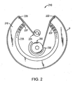
- the plate material may, for example, be packaged as a removable, replaceable cassette (as discussed in U.S. Patent Nos. 5,355,795 and 5,435,242 ), or on a supply spool that may be introduced into and withdrawn from the body of the cylinder (see U.S. Patent No. 5,727,749 ). As illustrated in FIG.
- plate material from a supply spool 205 emerges from a space or gap 210 in a cylinder 215, passing across a first edge 220 of the gap and wrapping around cylinder 215, then re-entering the body of cylinder 215 over the opposed edge 222 of gap 210 onto an uptake spool 225.
- a suitable mechanism causes supply spool 205 to pay out fresh plate material P, which is advanced around the exterior of cylinder 215 and wound onto uptake spool 225.
- Supply spool 205 is locked and uptake spool 225 continues to be wound until a desired degree of circumferential tension is established.
- a heating element 230 having a partially cylindrical profile may circumferentially surround a portion of supply roll 225.
- a cooling element 235 e.g., a set of refrigeration coils 237 and appropriate heat-exchange hardware
- cylinder 215 is metal, and the plate material on the surface of cylinder 215 will therefore cool by conduction.
Landscapes
- Engineering & Computer Science (AREA)
- Mechanical Engineering (AREA)
- Manufacture Or Reproduction Of Printing Formes (AREA)
- Laminated Bodies (AREA)
- Supply, Installation And Extraction Of Printed Sheets Or Plates (AREA)
- Printing Plates And Materials Therefor (AREA)
Claims (17)
- Verfahren zum Montieren einer Druckplatte an einen Zylinder, wobei das Verfahren folgende Schritte umfasst:a. Schaffen einer Temperaturdifferenz zwischen der Platte und dem Zylinder, wobei eine Temperatur der Platte eine Temperatur des Zylinders überschreitet; undb. danach Wickeln der Platte um den Zylinder, wobei die Temperaturdifferenz bewirkt, dass die Platte gegen den Zylinder schrumpft.
- Verfahren nach Anspruch 1, wobei die Temperaturdifferenz zumindest 3 °C beträgt.
- Verfahren nach Anspruch 1, wobei die Temperaturdifferenz durch Erwärmen der Platte geschaffen wird.
- Verfahren nach Anspruch 3, wobei die Platte gleichmäßig erwärmt wird.
- Verfahren nach Anspruch 3, wobei die Temperaturdifferenz durch Kühlen des Zylinders geschaffen wird.
- Verfahren nach Anspruch 1, wobei die Platte von einer Rolle gezogen wird, die im Innern des Zylinders angeordnet ist und um die Außenfläche des Zylinders vorgerückt wird.
- Verfahren nach Anspruch 6, wobei die Rolle erwärmt wird.
- Verfahren nach Anspruch 6, wobei die Außenfläche des Zylinders gekühlt wird.
- Vorrichtung zum Montieren einer Druckplatte an einen Zylinder, wobei die Vorrichtung umfasst:a. Mittel zum Schaffen einer Temperaturdifferenz zwischen der Platte und dem Zylinder, bevor die Platte so um den Zylinder gewickelt wird, dass eine Temperatur der Platte eine Temperatur des Zylinders überschreitet; undb. Mittel um danach Wickeln der Platte um den Zylinder zu erleichtern, wobei die Temperaturdifferenz bewirkt, dass die Platte gegen den Zylinder schrumpft.
- Vorrichtung nach Anspruch 9, wobei das erleichternde Mittel Registrierstifte und Klammern umfasst.
- Verfahren nach Anspruch 9, wobei die Platte von einer Rolle gezogen wird, die im Innern des Zylinders angeordnet ist und um die Außenfläche des Zylinders vorgerückt wird, wobei das erleichternde Mittel umfasst:a. Mittel im Innern des Zylinders zum Tragen der Plattenmaterialrolle; undb. Mittel im Innern des Zylinders zum Empfangen des Plattenmaterials, das sich über eine Laufbahn von der Plattenmaterialrolle über die Außenfläche des Zylinders erstreckt.
- Vorrichtung nach Anspruch 11, wobei das Mittel zur Schaffung einer Temperaturdifferenz Mittel zum Erwärmen der Rolle umfasst.
- Vorrichtung nach Anspruch 11, wobei das Mittel zur Schaffung einer Temperaturdifferenz Mittel zum Kühlen zumindest der Außenfläche des Zylinders umfasst.
- Vorrichtung nach Anspruch 9, wobei die Temperaturdifferenz zumindest 3 °C beträgt.
- Vorrichtung nach Anspruch 9, wobei das Mittel zur Schaffung einer Temperaturdifferenz Mittel zum Erwärmen der Platte umfasst.
- Vorrichtung nach Anspruch 15, wobei das Erwärmungsmittel eine erwärmte Fläche umfasst, die im Wesentlichen der Platte entspricht.
- Vorrichtung nach Anspruch 9, wobei das Mittel zur Schaffung einer Temperaturdifferenz Mittel zum Kühlen des Zylinders umfasst.
Applications Claiming Priority (2)
| Application Number | Priority Date | Filing Date | Title |
|---|---|---|---|
| US10/643,036 US6868608B2 (en) | 2003-08-18 | 2003-08-18 | Plate handling with thermal tensioning |
| PCT/US2004/024973 WO2005018933A2 (en) | 2003-08-18 | 2004-08-03 | Printing plate handling with thermal tensioning |
Publications (2)
| Publication Number | Publication Date |
|---|---|
| EP1656258A2 EP1656258A2 (de) | 2006-05-17 |
| EP1656258B1 true EP1656258B1 (de) | 2010-01-06 |
Family
ID=34193780
Family Applications (1)
| Application Number | Title | Priority Date | Filing Date |
|---|---|---|---|
| EP04779899A Expired - Lifetime EP1656258B1 (de) | 2003-08-18 | 2004-08-03 | Druckplatten-handhabung mit thermischem spannen |
Country Status (5)
| Country | Link |
|---|---|
| US (1) | US6868608B2 (de) |
| EP (1) | EP1656258B1 (de) |
| AT (1) | ATE454267T1 (de) |
| DE (1) | DE602004025003D1 (de) |
| WO (1) | WO2005018933A2 (de) |
Families Citing this family (2)
| Publication number | Priority date | Publication date | Assignee | Title |
|---|---|---|---|---|
| TWI562380B (en) * | 2005-01-28 | 2016-12-11 | Semiconductor Energy Lab Co Ltd | Semiconductor device, electronic device, and method of manufacturing semiconductor device |
| CN112959805A (zh) * | 2021-03-11 | 2021-06-15 | 绍兴上虞威拓机械电子有限公司 | 压印印版预热双工位装置 |
Family Cites Families (16)
| Publication number | Priority date | Publication date | Assignee | Title |
|---|---|---|---|---|
| DE319378C (de) * | 1915-02-12 | 1920-03-04 | Maschf Augsburg Nuernberg Ag | Verfahren und Vorrichtung zum Aufspannen von Formblechen fuer Tiefdruck auf Formzylinder |
| US2219085A (en) * | 1938-09-01 | 1940-10-22 | Charles G Watson | Method of covering rollers |
| US3759800A (en) | 1971-09-27 | 1973-09-18 | Screen Printing Systems | Seamless rotary printing screen and method of making same |
| US4026208A (en) | 1973-11-21 | 1977-05-31 | Raylar Corporation | Rotary printing screen having heat-shrunk support members |
| US4025751A (en) * | 1975-04-28 | 1977-05-24 | Xerox Corporation | Fuser roll sleeve |
| SE401907B (sv) | 1976-04-13 | 1978-06-05 | Levin Maskin Ab K E | Ram for silkescreentryck |
| JPS57107842A (en) * | 1980-12-26 | 1982-07-05 | Dainippon Printing Co Ltd | Attaching method of sleeve plate to printing roll in gravure printing |
| JPS6064791A (ja) * | 1983-09-16 | 1985-04-13 | Kawasaki Heavy Ind Ltd | 平板溶接構造における溶接後の板の弛みを防止する方法 |
| DE3525795C1 (de) | 1985-07-19 | 1987-02-26 | Rueesch Ferd Ag | Vorrichtung zur Schablonen-Endring-Montage von Siebdruckzylindern |
| CA1271623A (en) * | 1988-01-28 | 1990-07-17 | Yvon Tasse | Method of securing plastic roll to metal core roller |
| CH682382A5 (fr) * | 1990-04-25 | 1993-09-15 | Bobst Sa | Procédé de montage et de fixation d'une plaque d'impression sur le cylindre porte-plaque d'une machine d'impression. |
| DE4326835A1 (de) | 1993-08-10 | 1995-02-16 | Baldwin Gegenheimer Gmbh | Temperierungssystem für Druckmaschinenzylinder |
| JPH0752516A (ja) * | 1993-08-20 | 1995-02-28 | Riso Kagaku Corp | 印刷ドラム及びその製造方法 |
| US5678487A (en) * | 1995-11-15 | 1997-10-21 | Heidelberg Harris Inc. | Apparatus for mounting flexible plates in a printing unit |
| US5727749A (en) * | 1996-02-05 | 1998-03-17 | Presstek, Inc | Automatic plate-loading cylinder with constant circumferential tension |
| DE19857108A1 (de) | 1998-12-10 | 2000-06-15 | Baldwin Grafotec Gmbh | Temperiervorrichtung einer Druckmaschine |
-
2003
- 2003-08-18 US US10/643,036 patent/US6868608B2/en not_active Expired - Fee Related
-
2004
- 2004-08-03 AT AT04779899T patent/ATE454267T1/de not_active IP Right Cessation
- 2004-08-03 WO PCT/US2004/024973 patent/WO2005018933A2/en not_active Ceased
- 2004-08-03 EP EP04779899A patent/EP1656258B1/de not_active Expired - Lifetime
- 2004-08-03 DE DE602004025003T patent/DE602004025003D1/de not_active Expired - Lifetime
Also Published As
| Publication number | Publication date |
|---|---|
| ATE454267T1 (de) | 2010-01-15 |
| WO2005018933A2 (en) | 2005-03-03 |
| WO2005018933A3 (en) | 2005-07-14 |
| DE602004025003D1 (de) | 2010-02-25 |
| US6868608B2 (en) | 2005-03-22 |
| EP1656258A2 (de) | 2006-05-17 |
| US20050039315A1 (en) | 2005-02-24 |
Similar Documents
| Publication | Publication Date | Title |
|---|---|---|
| JP2695117B2 (ja) | 版印刷装置に用いるための版胴に版材料を巻き付けるための装置 | |
| JP4406525B2 (ja) | 脚輪のついたインキ装置を有する印刷ユニット | |
| KR101544664B1 (ko) | 플레이트 실린더 상에 인쇄 플레이트를 배치하기 위한 방법 | |
| EP0904200B1 (de) | Druckzylinder mit fester vorrichtung zum befestigen von druckplatten | |
| JP2007531053A (ja) | 熱現像フレキソ印刷スリーブ装置及び方法 | |
| EP1656258B1 (de) | Druckplatten-handhabung mit thermischem spannen | |
| EP1543966B1 (de) | Verfahren und Vorrichtung zur Erfassung der Fuge eines Flexodruckplattenvorläufers | |
| US20080236429A1 (en) | Imaging system with media carrier storage position | |
| US20020043165A1 (en) | Multicolor printing press | |
| US5224423A (en) | Method for mounting and fitting a printing plate on a plate cylinder of an offset printing machine | |
| EP0607649B1 (de) | Bildübertragungsgerät | |
| KR101735172B1 (ko) | 텐셔닝 슬라이드를 사용하여 플레이트 실린더 상에 인쇄 플레이트를 배치하기 위한 방법 | |
| US8286553B2 (en) | Wiffle-tree printing plate registration system | |
| JP2640233B2 (ja) | スリツタマシン | |
| JPH07266532A (ja) | オフセット印刷方法、それに用いるオフセット印刷機及びこの印刷方法を用いたカラーフィルタの製造方法 | |
| US10384473B2 (en) | Digital printing machine with a temperature control device for sheets | |
| US6324376B1 (en) | Heating apparatus | |
| US20240391268A1 (en) | Thermal development apparatus of flexographic plates | |
| US20090078139A1 (en) | Magnetic plate retention | |
| EP0593780B1 (de) | Bildübertragungsgerät | |
| US6543361B2 (en) | Method of increasing the service life of printing forms whereon images can be set in printing machines | |
| JP3694334B2 (ja) | 媒体処理装置 | |
| JP2970208B2 (ja) | 画像受容体用添着装置 | |
| JPH06238870A (ja) | 画像転写装置 | |
| JP2007076370A (ja) | 画像記録装置および印刷機 |
Legal Events
| Date | Code | Title | Description |
|---|---|---|---|
| PUAI | Public reference made under article 153(3) epc to a published international application that has entered the european phase |
Free format text: ORIGINAL CODE: 0009012 |
|
| 17P | Request for examination filed |
Effective date: 20060308 |
|
| AK | Designated contracting states |
Kind code of ref document: A2 Designated state(s): AT BE BG CH CY CZ DE DK EE ES FI FR GB GR HU IE IT LI LU MC NL PL PT RO SE SI SK TR |
|
| RIN1 | Information on inventor provided before grant (corrected) |
Inventor name: THERIAULT, EDWIN, G. Inventor name: LOVENSTEIN, JAMES, V. |
|
| DAX | Request for extension of the european patent (deleted) | ||
| 17Q | First examination report despatched |
Effective date: 20071106 |
|
| GRAP | Despatch of communication of intention to grant a patent |
Free format text: ORIGINAL CODE: EPIDOSNIGR1 |
|
| GRAS | Grant fee paid |
Free format text: ORIGINAL CODE: EPIDOSNIGR3 |
|
| GRAA | (expected) grant |
Free format text: ORIGINAL CODE: 0009210 |
|
| AK | Designated contracting states |
Kind code of ref document: B1 Designated state(s): AT BE BG CH CY CZ DE DK EE ES FI FR GB GR HU IE IT LI LU MC NL PL PT RO SE SI SK TR |
|
| REG | Reference to a national code |
Ref country code: GB Ref legal event code: FG4D |
|
| REG | Reference to a national code |
Ref country code: CH Ref legal event code: EP |
|
| REG | Reference to a national code |
Ref country code: IE Ref legal event code: FG4D |
|
| REF | Corresponds to: |
Ref document number: 602004025003 Country of ref document: DE Date of ref document: 20100225 Kind code of ref document: P |
|
| REG | Reference to a national code |
Ref country code: NL Ref legal event code: VDEP Effective date: 20100106 |
|
| PG25 | Lapsed in a contracting state [announced via postgrant information from national office to epo] |
Ref country code: SI Free format text: LAPSE BECAUSE OF FAILURE TO SUBMIT A TRANSLATION OF THE DESCRIPTION OR TO PAY THE FEE WITHIN THE PRESCRIBED TIME-LIMIT Effective date: 20100106 |
|
| PG25 | Lapsed in a contracting state [announced via postgrant information from national office to epo] |
Ref country code: AT Free format text: LAPSE BECAUSE OF FAILURE TO SUBMIT A TRANSLATION OF THE DESCRIPTION OR TO PAY THE FEE WITHIN THE PRESCRIBED TIME-LIMIT Effective date: 20100106 |
|
| PG25 | Lapsed in a contracting state [announced via postgrant information from national office to epo] |
Ref country code: NL Free format text: LAPSE BECAUSE OF FAILURE TO SUBMIT A TRANSLATION OF THE DESCRIPTION OR TO PAY THE FEE WITHIN THE PRESCRIBED TIME-LIMIT Effective date: 20100106 Ref country code: PT Free format text: LAPSE BECAUSE OF FAILURE TO SUBMIT A TRANSLATION OF THE DESCRIPTION OR TO PAY THE FEE WITHIN THE PRESCRIBED TIME-LIMIT Effective date: 20100506 Ref country code: ES Free format text: LAPSE BECAUSE OF FAILURE TO SUBMIT A TRANSLATION OF THE DESCRIPTION OR TO PAY THE FEE WITHIN THE PRESCRIBED TIME-LIMIT Effective date: 20100417 |
|
| PG25 | Lapsed in a contracting state [announced via postgrant information from national office to epo] |
Ref country code: FI Free format text: LAPSE BECAUSE OF FAILURE TO SUBMIT A TRANSLATION OF THE DESCRIPTION OR TO PAY THE FEE WITHIN THE PRESCRIBED TIME-LIMIT Effective date: 20100106 Ref country code: PL Free format text: LAPSE BECAUSE OF FAILURE TO SUBMIT A TRANSLATION OF THE DESCRIPTION OR TO PAY THE FEE WITHIN THE PRESCRIBED TIME-LIMIT Effective date: 20100106 |
|
| PG25 | Lapsed in a contracting state [announced via postgrant information from national office to epo] |
Ref country code: CY Free format text: LAPSE BECAUSE OF FAILURE TO SUBMIT A TRANSLATION OF THE DESCRIPTION OR TO PAY THE FEE WITHIN THE PRESCRIBED TIME-LIMIT Effective date: 20100106 Ref country code: EE Free format text: LAPSE BECAUSE OF FAILURE TO SUBMIT A TRANSLATION OF THE DESCRIPTION OR TO PAY THE FEE WITHIN THE PRESCRIBED TIME-LIMIT Effective date: 20100106 Ref country code: SE Free format text: LAPSE BECAUSE OF FAILURE TO SUBMIT A TRANSLATION OF THE DESCRIPTION OR TO PAY THE FEE WITHIN THE PRESCRIBED TIME-LIMIT Effective date: 20100106 Ref country code: GR Free format text: LAPSE BECAUSE OF FAILURE TO SUBMIT A TRANSLATION OF THE DESCRIPTION OR TO PAY THE FEE WITHIN THE PRESCRIBED TIME-LIMIT Effective date: 20100407 Ref country code: BE Free format text: LAPSE BECAUSE OF FAILURE TO SUBMIT A TRANSLATION OF THE DESCRIPTION OR TO PAY THE FEE WITHIN THE PRESCRIBED TIME-LIMIT Effective date: 20100106 Ref country code: RO Free format text: LAPSE BECAUSE OF FAILURE TO SUBMIT A TRANSLATION OF THE DESCRIPTION OR TO PAY THE FEE WITHIN THE PRESCRIBED TIME-LIMIT Effective date: 20100106 |
|
| PLBE | No opposition filed within time limit |
Free format text: ORIGINAL CODE: 0009261 |
|
| STAA | Information on the status of an ep patent application or granted ep patent |
Free format text: STATUS: NO OPPOSITION FILED WITHIN TIME LIMIT |
|
| PG25 | Lapsed in a contracting state [announced via postgrant information from national office to epo] |
Ref country code: SK Free format text: LAPSE BECAUSE OF FAILURE TO SUBMIT A TRANSLATION OF THE DESCRIPTION OR TO PAY THE FEE WITHIN THE PRESCRIBED TIME-LIMIT Effective date: 20100106 Ref country code: CZ Free format text: LAPSE BECAUSE OF FAILURE TO SUBMIT A TRANSLATION OF THE DESCRIPTION OR TO PAY THE FEE WITHIN THE PRESCRIBED TIME-LIMIT Effective date: 20100106 Ref country code: BG Free format text: LAPSE BECAUSE OF FAILURE TO SUBMIT A TRANSLATION OF THE DESCRIPTION OR TO PAY THE FEE WITHIN THE PRESCRIBED TIME-LIMIT Effective date: 20100406 |
|
| 26N | No opposition filed |
Effective date: 20101007 |
|
| PG25 | Lapsed in a contracting state [announced via postgrant information from national office to epo] |
Ref country code: DK Free format text: LAPSE BECAUSE OF FAILURE TO SUBMIT A TRANSLATION OF THE DESCRIPTION OR TO PAY THE FEE WITHIN THE PRESCRIBED TIME-LIMIT Effective date: 20100106 |
|
| PG25 | Lapsed in a contracting state [announced via postgrant information from national office to epo] |
Ref country code: IT Free format text: LAPSE BECAUSE OF FAILURE TO SUBMIT A TRANSLATION OF THE DESCRIPTION OR TO PAY THE FEE WITHIN THE PRESCRIBED TIME-LIMIT Effective date: 20100106 Ref country code: MC Free format text: LAPSE BECAUSE OF NON-PAYMENT OF DUE FEES Effective date: 20100831 |
|
| REG | Reference to a national code |
Ref country code: CH Ref legal event code: PL |
|
| PG25 | Lapsed in a contracting state [announced via postgrant information from national office to epo] |
Ref country code: CH Free format text: LAPSE BECAUSE OF NON-PAYMENT OF DUE FEES Effective date: 20100831 Ref country code: LI Free format text: LAPSE BECAUSE OF NON-PAYMENT OF DUE FEES Effective date: 20100831 |
|
| REG | Reference to a national code |
Ref country code: FR Ref legal event code: ST Effective date: 20110502 |
|
| PG25 | Lapsed in a contracting state [announced via postgrant information from national office to epo] |
Ref country code: FR Free format text: LAPSE BECAUSE OF NON-PAYMENT OF DUE FEES Effective date: 20100831 Ref country code: IE Free format text: LAPSE BECAUSE OF NON-PAYMENT OF DUE FEES Effective date: 20100803 |
|
| PG25 | Lapsed in a contracting state [announced via postgrant information from national office to epo] |
Ref country code: HU Free format text: LAPSE BECAUSE OF FAILURE TO SUBMIT A TRANSLATION OF THE DESCRIPTION OR TO PAY THE FEE WITHIN THE PRESCRIBED TIME-LIMIT Effective date: 20100707 Ref country code: LU Free format text: LAPSE BECAUSE OF NON-PAYMENT OF DUE FEES Effective date: 20100803 |
|
| PG25 | Lapsed in a contracting state [announced via postgrant information from national office to epo] |
Ref country code: TR Free format text: LAPSE BECAUSE OF FAILURE TO SUBMIT A TRANSLATION OF THE DESCRIPTION OR TO PAY THE FEE WITHIN THE PRESCRIBED TIME-LIMIT Effective date: 20100106 |
|
| PGFP | Annual fee paid to national office [announced via postgrant information from national office to epo] |
Ref country code: DE Payment date: 20130828 Year of fee payment: 10 |
|
| PGFP | Annual fee paid to national office [announced via postgrant information from national office to epo] |
Ref country code: GB Payment date: 20130827 Year of fee payment: 10 |
|
| REG | Reference to a national code |
Ref country code: DE Ref legal event code: R119 Ref document number: 602004025003 Country of ref document: DE |
|
| GBPC | Gb: european patent ceased through non-payment of renewal fee |
Effective date: 20140803 |
|
| REG | Reference to a national code |
Ref country code: DE Ref legal event code: R119 Ref document number: 602004025003 Country of ref document: DE Effective date: 20150303 |
|
| PG25 | Lapsed in a contracting state [announced via postgrant information from national office to epo] |
Ref country code: GB Free format text: LAPSE BECAUSE OF NON-PAYMENT OF DUE FEES Effective date: 20140803 Ref country code: DE Free format text: LAPSE BECAUSE OF NON-PAYMENT OF DUE FEES Effective date: 20150303 |