EP1655993B1 - Messeinrichtung zur Bestimmung der Rückkopplungsreserve - Google Patents
Messeinrichtung zur Bestimmung der Rückkopplungsreserve Download PDFInfo
- Publication number
- EP1655993B1 EP1655993B1 EP04746766.7A EP04746766A EP1655993B1 EP 1655993 B1 EP1655993 B1 EP 1655993B1 EP 04746766 A EP04746766 A EP 04746766A EP 1655993 B1 EP1655993 B1 EP 1655993B1
- Authority
- EP
- European Patent Office
- Prior art keywords
- gain
- howling
- level
- compressor
- measuring device
- Prior art date
- Legal status (The legal status is an assumption and is not a legal conclusion. Google has not performed a legal analysis and makes no representation as to the accuracy of the status listed.)
- Expired - Lifetime
Links
Images

Classifications
-
- H—ELECTRICITY
- H04—ELECTRIC COMMUNICATION TECHNIQUE
- H04R—LOUDSPEAKERS, MICROPHONES, GRAMOPHONE PICK-UPS OR LIKE ACOUSTIC ELECTROMECHANICAL TRANSDUCERS; ELECTRIC HEARING AIDS; PUBLIC ADDRESS SYSTEMS
- H04R29/00—Monitoring arrangements; Testing arrangements
- H04R29/007—Monitoring arrangements; Testing arrangements for public address systems
-
- H—ELECTRICITY
- H04—ELECTRIC COMMUNICATION TECHNIQUE
- H04R—LOUDSPEAKERS, MICROPHONES, GRAMOPHONE PICK-UPS OR LIKE ACOUSTIC ELECTROMECHANICAL TRANSDUCERS; ELECTRIC HEARING AIDS; PUBLIC ADDRESS SYSTEMS
- H04R3/00—Circuits for transducers
- H04R3/02—Circuits for transducers for preventing acoustic reaction, i.e. acoustic oscillatory feedback
-
- H—ELECTRICITY
- H04—ELECTRIC COMMUNICATION TECHNIQUE
- H04R—LOUDSPEAKERS, MICROPHONES, GRAMOPHONE PICK-UPS OR LIKE ACOUSTIC ELECTROMECHANICAL TRANSDUCERS; ELECTRIC HEARING AIDS; PUBLIC ADDRESS SYSTEMS
- H04R2227/00—Details of public address [PA] systems covered by H04R27/00 but not provided for in any of its subgroups
- H04R2227/007—Electronic adaptation of audio signals to reverberation of the listening space for PA
-
- H—ELECTRICITY
- H04—ELECTRIC COMMUNICATION TECHNIQUE
- H04R—LOUDSPEAKERS, MICROPHONES, GRAMOPHONE PICK-UPS OR LIKE ACOUSTIC ELECTROMECHANICAL TRANSDUCERS; ELECTRIC HEARING AIDS; PUBLIC ADDRESS SYSTEMS
- H04R27/00—Public address systems
Definitions
- the present invention relates to a howling margin measuring device for measuring the howling margin of an acoustic system.
- the howling margin of an acoustic system that includes microphones and speakers such as installed in a concert hall needs to be obtained in some cases.
- Such a howling margin has been heretofore measured by the following method.
- acoustic systems are equipped with a means for gain control.
- the gain of the acoustic system is also set to a value appropriate for use in the concert.
- a measurement of the howling margin of the acoustic system thus adjusted and set is generally made by a gain controlling means provided for the acoustic system.
- a gain controlling means provided for the acoustic system.
- an output fader for a mixing console placed between a microphone and a speaker is commonly used.
- the operator controls the gain of the gain controlling means so as to gradually increase from the reference level.
- the gain of the gain controlling means is increased by the operator.
- the speaker makes sound waves having a specified frequency (howling frequency).
- the operator aurally checks this sound thereby knowing that generation of howling has started. Then, he obtains a howling margin from how much the gain of the gain controlling means when howling starts exceeds the reference level. For instance, if the reference level of the fader that serves as the gain controlling means is "-10 dB" and the level of the fader when the acoustic system starts howling is "-5 dB", the howling margin is "5 dB".
- GREENBERG JULIE ET AL "Evaluation of feedback-reduction algorithms for hearing aids" JOURNAL OF THE ACOUSTICAL SOCIETY OF AMERICA, AIP/ ACOUSTICAL SOCIETY OF AMERICA, MELVILLE, NY, US, vol. 108, no. 5, 1 November 2000 (2000-11-01), pages 2366-2376, XP012002015 ISSN: 0001-4966 discloses a feedback reduction algorithm for a hearing aid.
- a primary object of the invention is to provide a measuring device capable of making an objective and accurate measurement of a howling margin without depending upon the sense of hearing of the operator.
- a howling margin can be objectively and accurately measured without depending upon the sense of hearing of the operator.
- the howling margin measuring device is formed such that the determination on whether howling has been generated is done based on whether a condition in which the read compression level is equal to or higher than a specified level has continued for a specified period of time, which enables a correct judgment of howling generation.
- the howling margin measuring device has displaying means for displaying a calculated howling margin.
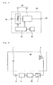
- Fig. 1 is a block diagram of a howling margin measuring device 20 according to one embodiment of the invention.
- the howling margin measuring device 20 has a processing unit (processing means) 28, a control unit (controlling means) 23 and a display unit 24.
- the processing unit 28 is comprised of a gain controller (gain controlling means) 21 located in an anterior stage and a compressor 22 located in a posterior stage, which are connected in series.
- the gain controller 21 inputs an acoustic signal from an input terminal 25 serving as an input unit and outputs this signal after adding a gain to it.
- the gain of the gain controller 21 can be arbitrarily set within the range of "-20 (dB)" to "+20 (dB)".
- the compressor 22 inputs an output signal of the gain controller 21 and outputs this signal to the output terminal 26 after processing it.
- the processing performed by the compressor 22 is compression of an input signal with a preset ratio, the input signal having a level higher than a preset threshold level.
- the threshold level can be arbitrarily set within the range of "0 (dB)” to “10 (dB)”.
- the ratio can be arbitrarily set within the range of "1/1" to " ⁇ /1".
- the state where the ratio is "1/1” is such that even if the level of the input signal exceeds the threshold level, compression of the input signal will not be done at all.
- the state where the ratio is " ⁇ /1” is such that if the level of the input signal exceeds the threshold level, the input signal is compressed until the threshold level is reached irrespective of the magnitude of the level (of the input signal).
- the control unit 23 can control the gain controller 21 and the compressor 22. More particularly, it can control the gain of the gain controller 21, the threshold level for the compressor 22 and the ratio for the compressor 22.
- the control unit 23 can read the compression level of the compressor 22.
- the control unit 23 has a computing function and a timing function. Further, it can control driving of the display unit 24.
- Fig. 2 is a block diagram showing a condition in which the howling margin measuring device 20 is incorporated into an acoustic system.
- the acoustic system is installed in a concert hall 40.
- the acoustic system includes a microphone 1, a microphone amplifier 2, a mixing console 3, a power amplifier 4 and a speaker 5.
- An output signal from the microphone 1 is input to the mixing console 3 through the microphone amplifier 2. After adjusted by the mixing console 3, the signal is amplified by the power amplifier 4 and made audible by the speaker 5.
- the howling margin measuring device 20 is interposed between the mixing console 3 and power amplifier 4 of the acoustic system.
- Figs. 1 and 2 describe the operation of the howling margin device 20 when measuring the howling margin of the acoustic system installed in the concert hall 40.
- the howling margin measuring device 20 starts operation provided that the acoustic system installed in the concert hall 40 is adjusted and set so as to be in a usable condition. Specifically, this condition (i.e., the condition in which the acoustic system is adjusted and set so as to be usable in a concert) is utilized as a reference state and the howling margin of the acoustic system in this reference state is measured by the howling margin measuring device 20.
- the adjustment and setting of the acoustic system to bring it into the reference state can be done by the operator or by an automatic adjustment system (not shown).
- the howling margin measuring device 20 may be set to 0 dB and the ratio may be set to "1/1" so that the compression level of the compressor 22 is constantly kept to be 0 dB.
- the howling margin measuring device 20 After completion of the adjustment and setting to bring the acoustic system into its reference condition, the howling margin measuring device 20 starts up.
- the initial condition of the gain controller 21 is a condition in which gain is set to a value that is small enough not to cause howling in the acoustic system.
- the gain of the gain controller 21 is set to "0 dB".
- the setting of the gain of the gain controller 21 is done by the control unit 23.
- the initial condition of the compressor 22 is a condition in which the threshold level for the compressor 22 is set to a specified value and the ratio is set to a specified value.
- the threshold level is set to "6 dB" and the ratio is set to a value exceeding "1/1" such as "2/1 ".
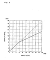
- Fig. 3 is an input/output characteristic graph of the compressor 22.
- Solid line in Fig. 3 is a characteristic line of the compressor 22 in the initial condition described above (that is, the threshold level is 6dB and the ratio is "2/1 ").
- Broken line in Fig. 3 is a characteristic line of the compressor 22 when no compression is done at all. The difference between the broken line and the sold line when the input level is equal to or higher than the threshold level (6 dB) is the compression level.
- the gain of the gain controller 21 is gradually increased in the howling margin measuring device 20.
- the gain is increased by a specified level per unit time. In this embodiment, the gain increases at a speed of "1 dB/sec".
- the gain control of the gain controller 21 is also performed by the control unit 23.
- control unit 23 monitors the compression level of the compressor 22. Since the control unit 23 can read the compression level of the compressor 22, the compression level can be obtained at any time. Although the control unit 23 reads the compression level at certain time intervals, it looks like monitoring the compression level in a substantially continuous manner since the time interval of reading is short.
- control unit 23 gradually increases the gain of the gain controller 21 while constantly monitoring the compression level of the compressor 22.
- the gain of the gain controller 21 is sufficiently small, howling does not occur in the acoustic system. Therefore, the level of the output signal of the microphone 1 is small and the level of the signal input to the compressor 22 does not exceed the threshold level.
- the gain of the gain controller 21 becomes great to a certain degree, howling will occur at a specified frequency.
- howling occurs, the output signal level of the microphone 1 and therefore the level of the signal input to the compressor 22 rapidly increase. As a result, the level of the input signal of the compressor 22 exceeds the threshold level, causing the compressor 22 to start signal compression.
- the control unit 23 always monitors the compression level of the compressor 22 as discussed earlier and, at the same time, constantly makes a judgment to check if the compression level has a value equal to or higher than a specified value.
- the specified value is "1 dB”. If the compression level is judged to be 1 dB or more, timing starts, being triggered by this judgment. The monitoring of the compression level continues after the start of timing.
- the compression level does not become less than 1 dB after an elapse of a specified time (which is "5 seconds" in this embodiment) after the start of timing, it is then determined that howling has been being generated in the acoustic system and a howling margin is decided based on the gain of the gain controller 21 at the time of this determination.
- a howling margin based on the gain of the gain controller 21. For instance, the value, which is obtained from subtraction of a specified minute gain from the gain of the gain controller 21 when howling is judged to be generated, may be determined to be a howling margin. For instance, if the gain of the gain controller 21 when howling is generated is "9 dB" and the minute gain is "1 dB", the howling margin is determined to be "8 dB". This minute gain may be the minimum unit (i.e., the amount of gain increased by one step) of change in the gain that can be given to the gain controller 21 by the control unit 23.
- the control unit 23 controls the display unit 24 so as to display the howling margin thus determined (calculated).
- control unit 23 starts timing, being triggered by the judgment in which the compression level of the compressor 22 is determined to be 1 dB or more. However, if the compression level becomes less than 1 dB within a specified period of time (5 sec.) after the start of timing, it is not determined that howling has occurred and therefore the timing operation is reset. The reason for this is as follows.
- Fig. 4 is a graph of the level a of an input signal input to the howling margin measuring device 20, the gain b of the gain controller 21 and the compression level c of the compressor 22 which are plotted on a common time axis.
- Fig. 4 shows the state after the gain b of the gain controller 21 starts to rise until the compressor 22 starts compression.
- the gain b of the gain controller 21 gradually rises from 0 dB.
- the waveform at the level of - 10 dB or less is due to the background noise of the concert hall 40.
- An abrupt rise from the background noise level is seen at the input signal level a. This is due to generation of howling. Compression by the compressor 22 starts substantially simultaneously with the generation of howling.
- the howling margin measuring device 20 detects howling from the compressing condition of the compressor 22 without depending on the sense of hearing of the operator. And, it measures a howling margin based on the gain of the gain controller 21 and the compression level of the compressor 22. As a result, a howling margin can be objectively, accurately measured.
- the threshold level for the compressor 22 can be set low, which makes it possible to reliably control howling (feedback). Further, since the output level at the time of feedback generation can be limited to a low level by the compressor 22, damage to the acoustic system can be avoided, and an acoustic impact will not be given to the measurer.
- a howling margin is calculated, determining that howling has been generated, in cases where the condition in which the compression level of the compressor 22 is equal to or higher than a specified value (e.g., "1 dB") has continued for a specified period of time (e.g., 5 sec.).
- a specified value e.g., "1 dB”
- generation of howling may be determined immediately after detecting the condition in which the compression level of the compressor is equal to or higher than a specified level. In other words, generation of howling may be determined without confirming that the above condition has continued for the specified period of time.
- a howling margin may be calculated from the gain of the gain controlling means at that time.
- the processing unit 28 is formed such that the gain controller 21 is placed in an anterior stage while the compressor 22 being in a posterior stage.
- An alternative form of the processing unit 28 may be such that the compressor 22 is placed in an anterior stage with the gain controller 21 placed in a posterior stage and these components are connected in series. In this case, the processing unit can operate similarly to the processing unit 28 of the above embodiment.
- the howling margin measuring device of the invention is useful for the technical field of acoustic systems, because it can objectively accurately measure a howling margin for an acoustic system without depending on the skill of the operator.
Landscapes
- Health & Medical Sciences (AREA)
- General Health & Medical Sciences (AREA)
- Otolaryngology (AREA)
- Physics & Mathematics (AREA)
- Engineering & Computer Science (AREA)
- Acoustics & Sound (AREA)
- Signal Processing (AREA)
- Circuit For Audible Band Transducer (AREA)
- Control Of Amplification And Gain Control (AREA)
- Cable Transmission Systems, Equalization Of Radio And Reduction Of Echo (AREA)
Claims (2)
- Messeinrichtung (20) für die Rückkopplungsreserve, umfassend Verarbeitungsmittel (28), die sich zusammensetzen aus einem Verstärkungsregelmittel (21) und einem Kompressor (22), die in Reihe geschaltet sind, und ein Regelmittel (23);
wobei das Verstärkungsregelmittel (21) ein Eingangstonsignal ausgibt, nachdem es dieses verstärkt hat;
wobei, wenn der Pegel eines Tonsignals, das in den Kompressor (22) eingegeben wird, größer gleich einem Schwellenpegel ist, der Kompressor (22) das Tonsignal ausgibt, nachdem er dieses in einem vorgegebenen Verhältnis komprimiert hat;
wobei das Regelmittel (23) in der Lage ist, die Verstärkung des Verstärkungsregelmittels (21) zu regeln und einen Kompressionspegel des Kompressors (22) zu lesen, wobei der Kompressionspegel die Differenz zwischen dem Pegel des Tonsignals, das von dem Kompressor (22) ausgegeben wird, wenn keine Kompression durchgeführt wurde, und dem Pegel des Tonsignals, das von dem Kompressor (22) nach dem Komprimieren ausgegeben wird, ist; und
wobei das Regelmittel (23) den Kompressionspegel des Kompressors (23) liest und dabei die Verstärkung des Regelmittels (21) allmählich erhöht, auf der Grundlage davon, ob ein Zustand, in welchem der gelesene Kompressionspegel größer gleich einem vorgegebenen Pegel ist, einen vorgegebenen Zeitraum lang andauerte oder nicht bestimmt, dass Feedback erzeugt wurde, und eine Feedbackreserve durch Subtraktion einer vorgegebenen Verstärkung von der Verstärkung des Verstärkungsregelmittels (21) berechnet, wenn bestimmt wird, dass Feedback erzeugt wurde. - Messeinrichtung für die Rückkopplungsreserve nach Anspruch 1, umfassend Anzeigemittel (24) zum Anzeigen der berechneten Rückkopplungsreserve.
Applications Claiming Priority (2)
| Application Number | Priority Date | Filing Date | Title |
|---|---|---|---|
| JP2003277975A JP4059818B2 (ja) | 2003-07-23 | 2003-07-23 | ハウリングマージン測定装置 |
| PCT/JP2004/009297 WO2005011327A1 (ja) | 2003-07-23 | 2004-06-24 | ハウリングマージン測定装置 |
Publications (3)
| Publication Number | Publication Date |
|---|---|
| EP1655993A1 EP1655993A1 (de) | 2006-05-10 |
| EP1655993A4 EP1655993A4 (de) | 2009-06-10 |
| EP1655993B1 true EP1655993B1 (de) | 2013-06-19 |
Family
ID=34100778
Family Applications (1)
| Application Number | Title | Priority Date | Filing Date |
|---|---|---|---|
| EP04746766.7A Expired - Lifetime EP1655993B1 (de) | 2003-07-23 | 2004-06-24 | Messeinrichtung zur Bestimmung der Rückkopplungsreserve |
Country Status (4)
| Country | Link |
|---|---|
| US (1) | US7596238B2 (de) |
| EP (1) | EP1655993B1 (de) |
| JP (1) | JP4059818B2 (de) |
| WO (1) | WO2005011327A1 (de) |
Families Citing this family (2)
| Publication number | Priority date | Publication date | Assignee | Title |
|---|---|---|---|---|
| JP6369259B2 (ja) * | 2014-09-24 | 2018-08-08 | ヤマハ株式会社 | パラメータ制御装置及びプログラム |
| CN115529533B (zh) * | 2021-06-24 | 2025-07-04 | 珠海市杰理科技股份有限公司 | 一种啸叫预检测方法及装置、啸叫控制方法及装置 |
Family Cites Families (13)
| Publication number | Priority date | Publication date | Assignee | Title |
|---|---|---|---|---|
| NL8600406A (nl) * | 1986-02-18 | 1987-09-16 | Philips Nv | Automatisch geregeld versterkerstelsel. |
| AU5187990A (en) | 1989-03-02 | 1990-09-26 | Ensoniq Corporation | Apparatus and a method for fitting a hearing aid |
| JPH04225699A (ja) * | 1990-12-27 | 1992-08-14 | Matsushita Electric Ind Co Ltd | 音場制御装置 |
| JPH05308697A (ja) | 1992-05-06 | 1993-11-19 | Matsushita Electric Ind Co Ltd | ハウリング抑制装置 |
| JP3067409B2 (ja) | 1992-07-27 | 2000-07-17 | 日本ビクター株式会社 | ハウリング防止プロセッサ |
| JPH06350486A (ja) * | 1993-06-04 | 1994-12-22 | Nippon Telegr & Teleph Corp <Ntt> | 音響通信方式 |
| US5444788A (en) * | 1993-09-03 | 1995-08-22 | Akg Acoustics, Inc. | Audio compressor combining feedback and feedfoward sidechain processing |
| JPH09247787A (ja) * | 1996-03-04 | 1997-09-19 | Matsushita Electric Ind Co Ltd | 音場制御システム |
| JPH1066197A (ja) * | 1996-08-13 | 1998-03-06 | Shuichi Mimura | 拡声器のハウリング除去装置 |
| DE19904538C1 (de) * | 1999-02-04 | 2000-07-13 | Siemens Audiologische Technik | Verfahren zur Rückkopplungserkennung in einem Hörgerät und Hörgerät |
| AUPP999199A0 (en) | 1999-04-28 | 1999-05-20 | Telstra Corporation Limited | Apparatus and method for detecting far end speech |
| EP1309225B1 (de) * | 2002-10-02 | 2014-04-16 | Phonak Ag | Verfahren zur Bestimmung einer Rückkopplungsschwelle in einem Hörgerät |
| DE102004043005A1 (de) * | 2004-09-02 | 2006-03-09 | Biotronik Vi Patent Ag | Signalverarbeitungsvorrichtung für physiologische Signale |
-
2003
- 2003-07-23 JP JP2003277975A patent/JP4059818B2/ja not_active Expired - Lifetime
-
2004
- 2004-06-24 WO PCT/JP2004/009297 patent/WO2005011327A1/ja not_active Ceased
- 2004-06-24 EP EP04746766.7A patent/EP1655993B1/de not_active Expired - Lifetime
- 2004-06-24 US US10/565,357 patent/US7596238B2/en not_active Expired - Lifetime
Also Published As
| Publication number | Publication date |
|---|---|
| US7596238B2 (en) | 2009-09-29 |
| JP4059818B2 (ja) | 2008-03-12 |
| EP1655993A4 (de) | 2009-06-10 |
| US20070165893A1 (en) | 2007-07-19 |
| JP2005045569A (ja) | 2005-02-17 |
| EP1655993A1 (de) | 2006-05-10 |
| WO2005011327A1 (ja) | 2005-02-03 |
Similar Documents
| Publication | Publication Date | Title |
|---|---|---|
| EP2494792B1 (de) | Verfahren und System zur Sprachverbesserung | |
| US8249271B2 (en) | Noise analysis and extraction systems and methods | |
| US5442712A (en) | Sound amplifying apparatus with automatic howl-suppressing function | |
| JP5256190B2 (ja) | オーディオ再生機器において使用される自動騒音補償のための方法および装置 | |
| DK2355548T3 (en) | A method for detecting the pipe in an audio system | |
| US20070223733A1 (en) | Ambient Noise Sound Level Compensation | |
| EP2082614B1 (de) | Hörgerät mit verschlussreduktionseinheit und verschlussreduktionsverfahren | |
| CN103037289A (zh) | 扬声器输出的控制 | |
| WO2003081947A1 (en) | Method for dynamic determination of time constants, method for level detection, method for compressing an electric audio signal and hearing aid, wherein the method for compression is used | |
| CN104918181A (zh) | 电平调整装置和方法 | |
| Spriet et al. | Evaluation of feedback reduction techniques in hearing aids based on physical performance measures | |
| EP1655993B1 (de) | Messeinrichtung zur Bestimmung der Rückkopplungsreserve | |
| US11388514B2 (en) | Method for operating a hearing device, and hearing device | |
| US11418870B2 (en) | Volume adjustment device and volume adjustment method | |
| CN118102155B (zh) | 麦克风的增益方法及系统 | |
| JP3097376B2 (ja) | ハウリング抑制装置 | |
| EP0101469A1 (de) | Verfahren und einrichtung zum dämpfen von transienten | |
| JPH04363995A (ja) | 音声処理装置 | |
| US8090118B1 (en) | Strength discriminating probabilistic ringing feedback detector | |
| JPH03237899A (ja) | ハウリング抑制装置 | |
| JPH02176796A (ja) | 音声認識装置 | |
| JP3237350B2 (ja) | 自動利得制御装置 | |
| JP3067409B2 (ja) | ハウリング防止プロセッサ | |
| JPS63260209A (ja) | 自動利得制御装置 | |
| JPS607497A (ja) | 音声認識装置 |
Legal Events
| Date | Code | Title | Description |
|---|---|---|---|
| PUAI | Public reference made under article 153(3) epc to a published international application that has entered the european phase |
Free format text: ORIGINAL CODE: 0009012 |
|
| 17P | Request for examination filed |
Effective date: 20060202 |
|
| AK | Designated contracting states |
Kind code of ref document: A1 Designated state(s): DE GB |
|
| DAX | Request for extension of the european patent (deleted) | ||
| RBV | Designated contracting states (corrected) |
Designated state(s): DE GB |
|
| A4 | Supplementary search report drawn up and despatched |
Effective date: 20090512 |
|
| 17Q | First examination report despatched |
Effective date: 20090731 |
|
| GRAP | Despatch of communication of intention to grant a patent |
Free format text: ORIGINAL CODE: EPIDOSNIGR1 |
|
| GRAS | Grant fee paid |
Free format text: ORIGINAL CODE: EPIDOSNIGR3 |
|
| GRAA | (expected) grant |
Free format text: ORIGINAL CODE: 0009210 |
|
| AK | Designated contracting states |
Kind code of ref document: B1 Designated state(s): DE GB |
|
| REG | Reference to a national code |
Ref country code: GB Ref legal event code: FG4D |
|
| REG | Reference to a national code |
Ref country code: DE Ref legal event code: R096 Ref document number: 602004042478 Country of ref document: DE Effective date: 20130814 |
|
| PLBE | No opposition filed within time limit |
Free format text: ORIGINAL CODE: 0009261 |
|
| STAA | Information on the status of an ep patent application or granted ep patent |
Free format text: STATUS: NO OPPOSITION FILED WITHIN TIME LIMIT |
|
| 26N | No opposition filed |
Effective date: 20140320 |
|
| REG | Reference to a national code |
Ref country code: DE Ref legal event code: R097 Ref document number: 602004042478 Country of ref document: DE Effective date: 20140320 |
|
| REG | Reference to a national code |
Ref country code: DE Ref legal event code: R082 Ref document number: 602004042478 Country of ref document: DE |
|
| PGFP | Annual fee paid to national office [announced via postgrant information from national office to epo] |
Ref country code: DE Payment date: 20230621 Year of fee payment: 20 |
|
| PGFP | Annual fee paid to national office [announced via postgrant information from national office to epo] |
Ref country code: GB Payment date: 20230620 Year of fee payment: 20 |
|
| REG | Reference to a national code |
Ref country code: DE Ref legal event code: R071 Ref document number: 602004042478 Country of ref document: DE |
|
| PG25 | Lapsed in a contracting state [announced via postgrant information from national office to epo] |
Ref country code: GB Free format text: LAPSE BECAUSE OF EXPIRATION OF PROTECTION Effective date: 20240623 |
|
| REG | Reference to a national code |
Ref country code: GB Ref legal event code: PE20 Expiry date: 20240623 |
|
| PG25 | Lapsed in a contracting state [announced via postgrant information from national office to epo] |
Ref country code: GB Free format text: LAPSE BECAUSE OF EXPIRATION OF PROTECTION Effective date: 20240623 |