EP1655737A2 - Aufbewahrungsgehäuse und Verfahren zu seiner Herstellung - Google Patents
Aufbewahrungsgehäuse und Verfahren zu seiner Herstellung Download PDFInfo
- Publication number
- EP1655737A2 EP1655737A2 EP05255508A EP05255508A EP1655737A2 EP 1655737 A2 EP1655737 A2 EP 1655737A2 EP 05255508 A EP05255508 A EP 05255508A EP 05255508 A EP05255508 A EP 05255508A EP 1655737 A2 EP1655737 A2 EP 1655737A2
- Authority
- EP
- European Patent Office
- Prior art keywords
- pieces
- turning
- portions
- side plates
- bent
- Prior art date
- Legal status (The legal status is an assumption and is not a legal conclusion. Google has not performed a legal analysis and makes no representation as to the accuracy of the status listed.)
- Withdrawn
Links
- 238000003860 storage Methods 0.000 title claims abstract description 132
- 238000000034 method Methods 0.000 title claims description 13
- 230000003287 optical effect Effects 0.000 claims abstract description 73
- 238000003780 insertion Methods 0.000 claims abstract description 47
- 230000037431 insertion Effects 0.000 claims abstract description 47
- 238000000605 extraction Methods 0.000 claims abstract description 28
- 238000005452 bending Methods 0.000 claims description 11
- 230000007306 turnover Effects 0.000 abstract description 5
- 229920006257 Heat-shrinkable film Polymers 0.000 description 7
- 238000004519 manufacturing process Methods 0.000 description 7
- 229920003002 synthetic resin Polymers 0.000 description 7
- 239000000057 synthetic resin Substances 0.000 description 7
- 230000000007 visual effect Effects 0.000 description 7
- 238000012856 packing Methods 0.000 description 4
- 239000000853 adhesive Substances 0.000 description 3
- 230000001070 adhesive effect Effects 0.000 description 3
- 238000004806 packaging method and process Methods 0.000 description 3
- 239000000123 paper Substances 0.000 description 3
- 239000004745 nonwoven fabric Substances 0.000 description 2
- 239000004743 Polypropylene Substances 0.000 description 1
- 238000010276 construction Methods 0.000 description 1
- 238000005520 cutting process Methods 0.000 description 1
- 238000006073 displacement reaction Methods 0.000 description 1
- 238000004090 dissolution Methods 0.000 description 1
- 239000005022 packaging material Substances 0.000 description 1
- -1 polypropylene Polymers 0.000 description 1
- 229920001155 polypropylene Polymers 0.000 description 1
- 238000004064 recycling Methods 0.000 description 1
- 239000004065 semiconductor Substances 0.000 description 1
- 238000004904 shortening Methods 0.000 description 1
- 239000002699 waste material Substances 0.000 description 1
Images





Classifications
-
- G—PHYSICS
- G11—INFORMATION STORAGE
- G11B—INFORMATION STORAGE BASED ON RELATIVE MOVEMENT BETWEEN RECORD CARRIER AND TRANSDUCER
- G11B33/00—Constructional parts, details or accessories not provided for in the other groups of this subclass
- G11B33/02—Cabinets; Cases; Stands; Disposition of apparatus therein or thereon
- G11B33/04—Cabinets; Cases; Stands; Disposition of apparatus therein or thereon modified to store record carriers
- G11B33/0405—Cabinets; Cases; Stands; Disposition of apparatus therein or thereon modified to store record carriers for storing discs
- G11B33/0433—Multiple disc containers
- G11B33/0438—Multiple disc containers for disc cartridges
-
- G—PHYSICS
- G11—INFORMATION STORAGE
- G11B—INFORMATION STORAGE BASED ON RELATIVE MOVEMENT BETWEEN RECORD CARRIER AND TRANSDUCER
- G11B33/00—Constructional parts, details or accessories not provided for in the other groups of this subclass
- G11B33/02—Cabinets; Cases; Stands; Disposition of apparatus therein or thereon
- G11B33/04—Cabinets; Cases; Stands; Disposition of apparatus therein or thereon modified to store record carriers
- G11B33/0405—Cabinets; Cases; Stands; Disposition of apparatus therein or thereon modified to store record carriers for storing discs
- G11B33/0494—Cabinets; Cases; Stands; Disposition of apparatus therein or thereon modified to store record carriers for storing discs packages made by folding
Definitions
- the present invention relates to a storage casing suitable for storing a plurality of thin articles being stored, in particular, optical information recording media such as optical disks, etc., and a method of assembling the storage casing.
- optical disks Being one of recording media that record an information signal, optical disks are not sold one by one, but are in many cases sold in a package, in which a plurality of optical disks are packed. Concretely, optical disks are sold in a state, in which optical disks are stored one by one in storage casings made of a transparent or translucent synthetic resin and having stiffness in the order of a thickness of 4 mm to 10 mm, and a plurality of storage casings with optical disks stored therein are packed and wrapped up in a lump by heat shrinkable film or the like. In other sales configurations, a plurality of optical disks stacked with a spindle of a spindle casing inserted through central holes of the optical disks are packed and wrapped up by heat shrinkable film or the like.
- optical disks are stored one by one in sleeve casings being flexible and made of a transparent or translucent synthetic resin mixed with paper and nonwoven fabric, and a plurality of sleeve casings with optical disks stored therein are received in a single packing casing.
- Storage casings owned by every user are increasing in number, so that it becomes troublesome to find out a desired optical disk.
- Storage casings having the stiffness and a thickness in the order of 10 mm include a backbone enabling writing thereon information related to recorded information signals, but the work of taking out a backbone from a storage casing is troublesome and such storage casings are not made use of in many cases.
- Storage casings having a thickness of less than 10 mm and made of a synthetic resin are thin, and cannot receive a backbone.
- optical disks stored in a spindle casing and optical disks stored in a sleeve casing are not provided with paper for writing of memos.
- Storage casings with a recorded optical disk stored therein are in many cases stacked in a vertical or horizontal position to be stored in a packing casing. Also, optical disks stored in a sleeve casing continue in many cases to be stored in a packing casing been used since selling.
- a packing casing When a packing casing is stored, optical disks put in a state of being stored in a storage casing or a sleeve casing are stacked in a vertical or horizontal position, so that when memos, such as title, etc, related to contents recorded in an optical disk are directly written on the optical disk, a region, in which memos are written, hides behind an adjacent storage casing or an adjacent sleeve casing to make retrieval hard.
- storage casings need an adhesive in assembly and include a plurality of parts to cause a problem that manufacturing processes are increased in number.
- Patent Document 1 JP-A-2001-97472 discloses a storage casing for a recording medium.
- the Patent Document 1 describes assembling a single sheet to assemble a storage casing storing therein a plurality of disk cartridges and taking in and out of disk cartridges through opening and closing a front plate, which is restricted in amount of turning by a pin being a separate member.
- only the front plate turns and turning is performed only by the front plate, so that opening can be performed only in one direction at the time of retrieval to make opening insufficient in freedom, which makes it hard to turn over disk cartridges and difficult to find a desired disk cartridge from a plurality of disk cartridges stored in the storage casing.
- the casings are increased in number, so that a range of turning is insufficient with only turning of the front plate as in the Patent Document 1, thus making it difficult to confirm an indication applied on an optical disk itself and a desired optical disk.
- the storage casing disclosed in the Patent Document 1 is easily influenced by weight balance of disk cartridge therein.
- the storage casing disclosed in the Patent Document 1 substantially uses a pin for turning of the front plate, so that parts are plural in number and it is not possible to adequately achieve shortening of manufacturing processes.
- the invention has been thought of in view of the problems and has its object to provide a storage casing that can hold thin stored articles therein in an upright position, achieve reduction in manufacturing processes and cost, enables easy visual observation of articles stored therein in spite of large and small amounts of articles stored therein, and makes retrieval of stored articles very easy, and a method of assembling the storage casing.
- a storage casing having a construction which is completed by simply assembling a single sheet body to enable simplifying manufacturing processes, and a method of assembling the storage casing.
- a storage casing comprises a storage casing for a recording medium, storing therein a thin stored article in an upright position, the storage casing comprising a bottom plate, a front plate provided on the bottom plate with a first hinge, which is composed of a first bent portion along a first side of the bottom plate, therebetween, a back plate provided on the bottom plate with a second hinge, which is composed of a second bent portion along a second side opposed to the first side, therebetween, and a pair of side plates provided on the back plate.
- the front plate is provided with turning pieces along the side plates
- the bottom plate is provided with turning restriction pieces along the side plates
- the turning restriction pieces are provided on sides thereof toward the back plate with first turning restriction portions, which engage with engaging parts of the turning pieces, and on sides thereof toward the front plate with second turning restriction portions, which engage with restriction portions provided on side edges of the side plates adjacent to the front plate.
- the storage casing comprises, for example, a single sheet body comprising a bottom plate, a front plate provided on a first side of the bottom plate with a first bent portion therebetween, a back plate provided on a second side of the bottom plate opposed to the first side with a second bent portion therebetween, a pair of side plates provided on third and fourth sides of the back plate adjacent to the second bent portion with third and fourth bent portions therebetween, turning pieces provided on fifth and sixth sides adjacent to the first bent portion of the front plate with fifth and sixth bent portions therebetween, and provided on tip ends thereof with engaging parts, turning restriction pieces provided on seventh and eight sides adjacent to the first and second sides of the bottom plate with seventh and eight bent portions therebetween, and provided on tip ends thereof with restriction pieces, with ninth and tenth bent portions, which are in parallel to the seventh and eight bent portions, therebetween, and holding pieces provided on the side plates with eleventh and twelfth bent portions, which are in parallel to the third and fourth bent portions, therebetween.
- the third and fourth bent portions are provided with latch holes, and the
- the storage casing is assembled by bending the turning restriction pieces at the seventh and eight bent portions and bending the restriction pieces at the ninth and tenth bent portions to form folds, and bending the pair of side plates at the third and fourth bent portions. Subsequently, the back plate is bent at the second bent portion so that the turning restriction pieces are positioned inside the side plates, and the holding pieces are bent at the eleventh and twelfth bent portions so as to surround the turning restriction pieces to put the restriction pieces formed with the folds in a state of being separate from the side plates. Subsequently, the turning pieces are bent at the fifth and sixth bent portions, the front plate is bent at the first bent portion, and the bent turning pieces are inserted from the insertion ports of the eleventh and twelfth bent portions. Subsequently, the storage casing is assembled by further folding the bent holding pieces at the eleventh and twelfth bent portions, and latching latch portions of the holding pieces in the latch holes of the third and fourth bent portions.
- the front plate when turning through the first hinge, the front plate can turn until the engaging parts of the turning pieces of the front plate engage with the first turning restriction portions and when turning through the second hinge, the back plate can turn until the restriction portions of the side plates engage with the second turning restriction portions, so that the insertion and extraction port for a thin stored article can be enlarged by opening the front plate and the back plate outward.
- thin stored articles can be held in an upright position, and display of thin stored articles and thin stored articles themselves become easy to confirm, thus making retrieval very easy.
- weight balance is made such that a plurality of thin stored articles inside can be distributed to the front plate side and the back plate side, so that it is possible to adjust an opening width with good balance.
- the invention in finding out a desired thin stored article out of thin stored articles stacked in the storage part, it is possible to enlarge an interval between adjacent thin stored articles, thus easily enabling visual observation of, for example, memos on surfaces of the thin stored articles to make retrieval easy.
- the invention is excellent in quality of retrieval, productivity, and quality of use to be especially suited to thin stored articles, such as optical information recording media, with display on one surface thereof.
- the invention can be constructed by assembling a single sheet body, so that it is possible to simplify an assembling process owing to reduction of parts in number and to achieve reduction in manufacturing cost.
- a storage casing 10, to which the invention is applied, shown in Figs. 1 and 2 stores therein a plurality of optical disks 1 being thin stored articles, and the whole storage casing 10 is packed and wrapped up by heat shrinkable film and displayed at the time of shipping and over the counter sale, the storage casing functioning as a filing casing that permits a user to store and keep therein a plurality of optical disks in use after being purchased by the user.
- the optical disks 1 stored in the storage casing can include an optical disk having, for example, a diameter of 12 cm, and more specifically, a write once type CD or rewritable CD (Compact Disc), DVD (Digital Versatile Disk), etc.
- the sleeve casing 2 is formed by fusing three sides of a sheet body made of a transparent or translucent synthetic resin such as polypropylene, etc.
- the storage casing 10 can store, for example, twenty optical disks 1 in a state, in which the optical disks 1 are stored in the sleeve casings 2.
- a user frequently makes a note of information, such as title, etc., relating to recorded contents on a non-signal recorded surface opposed to a signal recorded surface of the optical disk 1.
- the sleeve casing 2 is formed to be transparent or translucent whereby a note recorded by a user can be recognized from outside. Also, paper or nonwoven fabric 2b is stored in the sleeve casing 2 to protect the signal recorded surface of the optical disk 1.
- the sleeve casing 2 described above is a thin one among existing storage casings for the optical disks 1.
- the storage casing 10 according to the invention can store therein many optical disks 1.
- an article being stored in the storage casing 10 is not limited to a recording medium such as the optical disks 1 but is not limitative provided that it is a thin plate-shaped body.
- a stored article is not limited to an optical information recording medium such as CD, DVD, etc. described above but may be a disk cartridge, which stores an optical disk, a magneto-optic disk, a magnetic disk, etc., an IC card with a semiconductor memory used for a storage element, and the like.
- a disk cartridge, an IC card, or the like, of which a recording medium is not exposed outside directly, must not necessarily be stored in the storage casing 10 in a state of being stored in a casing, such as the sleeve casing 2, which protects a recording medium.
- the storage casing 10, in which the optical disk 1 in a state of being stored in the sleeve casing 2 is stored comprises, as shown in Figs. 1 and 2, a substantially rectangular-shaped bottom plate 11, a front plate 12 provided integrally on one of long sides of the bottom plate 11, a back plate 13 provided integrally on the other of the long sides of the bottom plate 11, and a pair of side plates 14, 15 provided integral with the back plate 13, the storage casing being formed therein with a storage part 16, in which 20 optical disks stored in the sleeve casing 2 are stored at maximum.
- the maximum number of optical disks as stored is not limited to 20 but may be more or less than 20, which case can be coped with by changing a thickness of the storage part 16.
- the front plate 12 is formed to be lower than the back plate 13 and also lower than the sleeve casing 2 stored in the storage part 16, so that a substantially upper one third of the sleeve casing 2 stored in the storage part 16 is exposed to the front whereby the sleeve casing 2 stored in the storage part 16 and receiving therein the optical disk 1 is made easy to visually observe. That is, with the storage casing 10, the transparent or translucent sleeve casings 2 with the optical disks 1 stored therein are made liable to incline and turn over, thus facilitating visual observation of a note related to recorded contents and written on a non-signal recorded surface of the optical disk 1 through the sleeve casing 2.
- the back plate 13 is formed to be substantially the same in height as, or slightly lower than the sleeve casing 2 so that the sleeve casing 2 stored in the storage part 16 can be stored stably.
- a notch 16a is formed substantially centrally of an upper end of the back plate 13 so as to enable facilitating taking-out and putting-in of the sleeve casing 2 stored in the storage part 16.
- the side plates 14, 15, are formed to be substantially the same in height as the front plate 12 at the front sides thereof and to be increased in height toward the back plate 13.
- the side plates 14, 15 are formed such that upper ends thereof are increased in height toward the back from the front, whereby the side plates and the back plate 13 make it possible to stably store a plurality of the sleeve casings 2 in the storage part 16.
- back sides of the side plates 14, 15 are not made the same in height as the back plate 13 but formed to be somewhat lower than the back plate.
- the storage casing 10 having such external form is opened at a top, an upper portion of the front, and upper portions of the both sides to define an insertion and extraction port 17, through which insertion and extraction of the sleeve casings 2 are performed.
- a first bent portion formed by the bottom plate 11 and the front plate 12 defines, as shown in Fig. 2, a first hinge 18 that permits the front plate 12 to turn forwardly of the bottom plate 11, that is, in a direction of an arrow A in Figs. 1 and 2.
- a second bent portion formed by the bottom plate 11 and the back plate 13 defines a second hinge 19 that permits the back plate 13 to turn rearward, that is, in a direction of an arrow B in Figs. 1 and 2.
- the front plate 12 turns forward a predetermined angle, for example, 15°
- the back plate 13 turns rearward a predetermined angle, for example, 15°
- the insertion and extraction port 17 is opened 30° in total, whereby insertion and extraction of the sleeve casings 2 are made easy to perform and the sleeve casings 2 with the optical disks 1 stored therein are made liable to incline and turn over, thus making it possible to readily retrieve the optical disks 1 as stored.
- a turning angle of the front plate 12 and a turning angle of the back plate 13 are not limited to the angles described above and a turning angle of the front plate 12 and a turning angle of the back plate 13 may be different from each other. Also, turning angles of the front plate 12 and the back plate 13 can be appropriately changed depending upon a shape, a size, and a weight of a stored article, or the like.
- the side plates 14, 15 are further provided therein with holding pieces 21, 22 to make sides of the storage casing 10 double-structured.
- holding pieces 21, 22 Provided between the side plates 14, 15 and the holding pieces 21, 22 are turning pieces 23, 24 provided midway on both side edges of the front plate 12 and turning restriction pieces 25, 26 provided on both side edges of the bottom plate 11, so that turning of the front plate 12 and turning of the back plate 13 are performed with the turning pieces 23, 24 and the turning restriction pieces 25, 26.
- the turning pieces 23, 24 are integrally provided midway on both side edges of the front plate 12 to be bent substantially 90° along the side plates 14, 15.
- the turning pieces 23, 24 are formed to be curved downward, and formed at tip ends thereof with engaging parts 23a, 24a for engagement with the turning restriction pieces 25, 26.
- the turning pieces 23, 24 are inserted between the side plates 14, 15 and the holding pieces 21, 22 from insertion ports 23b, 24b provided on bent portions of the side plates 14, 15 and the holding pieces 21, 22.
- the turning restriction pieces 25, 26 are integrally provided on opposite short sides of the bottom plate 11 to be bent upward substantially 90°. Restriction pieces 27, 28 are further provided integrally on a side of the turning restriction pieces 25, 26 toward the front plate 12 in a direction of extension of the turning restriction pieces. The turning restriction pieces 25, 26 and the restriction pieces 27, 28 contiguous to and integral with the turning restriction pieces 25, 26 are inserted between the side plates 14, 15 and the holding pieces 21,22.
- first turning restriction portions 25b, 26b Side edges of the restriction pieces 27, 28 contiguous to the upper ends 25a, 26a of the turning restriction pieces 25, 26 and toward the back plate 13 define first turning restriction portions 25b, 26b, with which the engaging parts 23a, 24a of the turning pieces 23, 24 engage.
- the first turning restriction portions 25b, 26b are engaged by insides of the engaging parts 23a, 24a of the turning pieces 23, 24 to restrict thereby an amount of turning of the front plate 12.
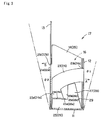
- the first turning restriction portions 25b, 26b permit the front plate 12 to turn relative to the bottom plate 11 by a turning angle ⁇ 1 (for example, 15°) in Fig. 3.
- Second turning restriction portions 25c, 26c that restrict an amount of turning of the back plate 13.
- the second turning restriction portions 25c, 26c abut against restriction portions 29 inside bent portions of the side plates 14, 15 and the holding pieces 21, 22 to permit the back plate 13 to turn relative to the bottom plate 11 by a turning angle ⁇ 2 (for example, 15°) in Fig. 3 when the back plate 13 turns relative to the bottom plate 11 in the direction of the arrow B in Figs. 1 to 3.
- the holding pieces 21, 22 cooperating with the side plates 14, 15 to interpose therebetween the turning restriction pieces 25, 26 and the restriction pieces 27, 28 are provided at tip ends thereof with latch portions 21a, 22a, so that the latch portions 21 a, 22a are latched in latch holes 21b, 22b, which are provided on bent portions of the back plate 13 and the side plates 14, 15, to be held in a substantially parallel to the side plates 14, 15.
- the turning pieces 23, 24 and the turning restriction pieces 25, 26 are interposed between the side plates 14, 15 and the holding pieces 21, 22, and the turning pieces 23, 24 and the turning restriction pieces 25, 26 are made to surely engage with and disengage from each other, so that it is possible to surely restrict amounts of turning of the front plate 12 and the back plate 13.
- the turning pieces 23, 24, the turning restriction pieces 25, 26, and the holding pieces 21, 22 may be provided only on either of the sides provided that the front plate 12 and the back plate 13 can be pivotally supported with a sufficient strength.
- the storage casing 10 makes it possible to cause the sleeve casings 2, which store the optical disks 1 therein and are stored in the storage part 16, to be inclined and easily turned over one by one and to increase a spacing between adjacent sleeve casings 2 when a sleeve casing 2 is turned over, so that it is possible to facilitate visual observation of a note or the like related to recorded contents and written on a non-signal recorded surface of the optical disk 1. Also, in a state, in which the insertion and extraction port 17 is opened, the stored sleeve casings 2 can be inclined and distributed to the front plate 12 and the back plate 13 whereby the storage casing 10 can be readily varied in weight balance.
- the storage casing 10 may be composed of plural parts and assembled with the use of an adhesive, an adhesive member such as adhesion tape, or the like, it may be formed by assembling a single sheet body 31 as shown in Fig. 4.
- the sheet body 31 is formed from cardboard while it may be made from a synthetic-resin sheet or the like.
- the storage casing 10 formed from cardboard is made easily disposable by cutting, dissolution, etc., as compared with the case where it is made from a synthetic-resin sheet body.
- Fig. 4 is a development showing the storage casing 10.
- the sheet body 31 is provided centrally thereof with the substantially rectangular-shaped bottom plate 11.
- the substantially rectangular-shaped front plate 12 is formed on one of the long sides of the bottom plate 11 with a first bent portion 41 therebetween.
- the first bent portion 41 defines the first hinge 18 of the front plate 12.
- the substantially rectangular-shaped back plate 13 is formed on the other of the long sides of the bottom plate 11 with a second bent portion 42 therebetween.
- the second bent portion 42 defines the second hinge 19 of the back plate 13.
- the side plates 14, 15 are formed on third and fourth sides adjacent to the second bent portion 42 of the back plate 13 with third and fourth bent portions 43, 44 therebetween.
- the third and fourth bent portions 43, 44 are formed midway thereof with the latch holes 21 b, 22b, in which the latch portions 21 a, 22a of the holding pieces 21, 22 are latched.
- the latch holes 21b, 22b are formed to be the same as, or somewhat narrower than a thickness of the latch portions 21a, 22a, and permit the latch portions 21 a, 22a to be press fitted therein, thus enabling sure latching the latch portion 21 a, 22a.
- the turning pieces 23, 24 are formed on fifth and sixth sides adjacent to the first bent portion 41 of the front plate 12 with fifth and sixth bent portions 45, 46 therebetween.
- the engaging parts 23a, 24a are formed on tip ends of the turning pieces 23, 24.
- the turning restriction pieces 25, 26 are formed on seventh and eight short sides adjacent to the first and second bent portions 41, 42 of the bottom plate 11 with seventh and eight bent portions 47, 48 therebetween.
- the restriction pieces 27, 28 are formed on tip end sides of the turning restriction pieces 25, 26 with ninth and tenth bent portions 49, 50, which are in parallel to the seventh and eight bent portions 47, 48, therebetween.
- the holding pieces 21, 22 are formed on the side plates 14, 15 with eleventh and twelfth bent portions 51, 52, which are in parallel to the third and fourth bent portions 43, 44, therebetween.
- the eleventh and twelfth bent portions 51, 52 are formed midway thereof with the insertion ports 23b, 24b, into which the turning pieces 23, 24 are inserted.
- the insertion ports 23b, 24b are formed to be somewhat wider than a thickness of the turning pieces 23, 24, thus permitting the turning pieces 23, 24 to be smoothly moved.
- the latch portions 21a, 22a are formed on those sides of the holding pieces 21, 22, which are in parallel to the eleventh and twelfth bent portions 51, 52.
- the turning restriction pieces 25, 26 are bent inward through the seventh and eight bent portions 47, 48, and the restriction pieces 27, 28 are bent inward through the ninth and tenth bent portions 49, 50 to form folds as shown by (2) in Fig. 4.
- the side plates 14, 15 are bent inward through the third and fourth bent portions 43, 44 as shown by (3) in Fig. 4.
- the back plate 13 is bent at the second bent portion 42 so that the turning restriction pieces 25, 26 are positioned inside the side plates 14, 15 as shown by (4) in Fig. 4.
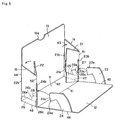
- the holding pieces 21, 22 are bent midway at the eleventh and twelfth bent portions 51, 52 in a manner to interpose therebetween the turning restriction pieces 25, 26, thus putting the state as shown in Fig. 5. That is, since the restriction pieces 27, 28 have folds at the ninth and tenth bent portions 49, 50, they are bent further inward relative to the turning pieces 23, 24 to be put in a state of being separate from the side plates 14, 15.
- the turning pieces 23, 24 are bent inward at the fifth and sixth bent portions 45, 46 and the front plate 12 is bent inward at the first bent portion 41 as shown by (7) in Fig. 4.
- the turning pieces 23, 24 are inserted into the insertion ports 23b, 24b, which are formed at the eleventh and twelfth bent portions 51, 52 between the side plates 14, 15 and the holding pieces 21, 22, with the engaging parts 23a, 24a thereof as ends of insertion as shown in Fig. 5.
- the restriction pieces 27, 28 have folds at the ninth and tenth bent portions 49, 50 and are put in a state of being separate from the side plates 14, 15, the engaging parts 23a, 24a can be smoothly inserted to sides of the restriction pieces 27, 28 toward the back plate 13 without striking on the restriction pieces 27, 28.
- the holding pieces 21, 22 having been bent midway are further folded toward the side plates 14, 15 so that the restriction pieces 27, 28 having folds are caused to strike against the side plates 14, 15 and the latch portions 21a, 22a of the holding pieces 21, 22 are latched in the latch holes 21b, 22b provided on the third and fourth bent portions 43, 44.
- the holding pieces 21, 22 are bent midway in a manner to cooperate with the side plates 14, 15 to interpose therebetween the turning restriction pieces 25, 26 and the restriction pieces 27, 28, and then the turning pieces 23, 24 are inserted into the insertion ports 23b, 24b on the eleventh and twelfth bent portions 51, 52, so that the turning pieces 23, 24 can be inserted to sides of the restriction pieces 27, 28 toward the back plate 13 without striking on the turning restriction pieces 25, 26 and the restriction pieces 27, 28.
- the restriction pieces 27, 28 with folds are caused to strike against the side plates 14, 15 to latch the latch portions 21a, 22a of the holding pieces 21, 22 in the latch holes 21 b, 22b provided on the third and fourth bent portions 43, 44, so that it is possible to assemble the storage casing 10, which eliminates displacement of the turning pieces 23, 24 and the turning restriction pieces 25, 26 in directions of bending to enable sure engagement and disengagement and can surely restrict amounts of turning of the front plate 12 and the back plate 13.
- the insertion ports 23b, 24b, into which the turning pieces 23, 24 are inserted are formed to be wider than a thickness of the turning pieces 23, 24, turning manipulation of the front plate 12 and the back plate 13 can be smoothly performed.
- the latch holes 21b, 22b, which are provided on the third and fourth bent portions 43, 44 between the back plate 13 and the side plates 14, 15 and in which the latch portions 21a, 22a of the holding pieces 21, 22 are latched are formed to be narrower than a thickness of the latch portions 21a, 22a, it is possible to surely latch the latch portions 21a, 22a and it is accordingly possible to prevent disassembly of the storage casing 10 in use.
- the storage casing 10 assembled in the above manner and shown in Figs. 1 and 2 is structured such that the front plate 12 is independently opened outward with the first hinge 18, which is defined by the first bent portion 41, as a pivot, and the back plate 13 is independently opened outward with the second hinge 19, which is defined by the second bent portion 42, as a pivot, it is possible to enlarge the insertion and extraction port 17.
- the sleeve casings 2, which store the optical disks 1 therein and are stacked and stored in the storage part 16, can be easily turned over one by one when a user performs retrieval, and a spacing between adjacent sleeve casings 2 can be enlarged, so that it is also possible to facilitate visual observation of a note or the like related to recorded contents and written on a non-signal recorded surface of the optical disk 1.
- the insertion and extraction port 17 when the insertion and extraction port 17 is opened in a state, in which a plurality of sleeve casings 2 storing the optical disks 1 therein are stored, the stored sleeve casings 2 are inclined and distributed to the front plate 12 and the back plate 13. Accordingly, articles stored in the storage casing 10 can be readily varied in weight balance, and the insertion and extraction port 17 can be freely varied in opening width, thus facilitating handling.
- the storage casing 10 is assembled by the use of a single cardboard, the user can readily dispose of it as combustible refuse when the storage casing 10 is damaged. Also, since the storage casing 10 is made of cardboard, there is no fear of breakage at the time of shipment or the like and it is possible to keep from use of synthetic resins, recycling of which is hard. Also, since the storage casing 10 is made of the single sheet body 31, it is possible to achieve reduction in number of parts and to facilitate assembly.
- the storage casing 10 is stored in the storage part 16 in a state, in which an optical disk is stored in the sleeve casing 2 being a thin one among existing storage casings, it can store many optical disks 1.
- the storage casing 10 functions as a filing casing continuously used by a user to store the optical disks 1 also after it is purchased by the user, and additionally functions as a package casing when a plurality of optical disks 1 are packaged and soled by heat shrinkable film.
- the insertion and extraction port 17 is closed by a lid body 61, which is a member separate from the storage casing 10, over the counter sale.
- the lid body 61 as the storage casing 10, is also formed from a single sheet body such as cardboard, etc.
- the sheet body comprises an insertion plate 62 being substantially rectangular-shaped and inserted between the back plate 13 and the sleeve casing 2 stored in the storage part 16, an upper plate 63 that covers a top of the insertion and extraction port 17, and a cover plate 64 that covers a front side of the insertion and extraction port 17 and the front plate 12, the sheet body being formed to be generally substantially C-shaped.
- the insertion plate 62 is bent inward relative to the upper plate 63 with a bent portion therebetween to be thereby formed, and the cover plate 64 is bent inward relative to the upper plate 63 to be thereby formed.
- the lid body 61 closes the insertion and extraction port 17 of the storage casing 10 in a manner to insert the insertion plate 62 between the back plate 13 and the sleeve casing 2 stored in the storage part 16 and to cause the cover plate 64 to cover the front plate 12 from outside.
- the storage casing 10 is put in a a state, in which the insertion and extraction port 17 is closed by the lid body 61, and generally covered by a transparent or translucent heat shrinkable film to be made one package.
- the lid body 61 does not close portions above the side plates 14, 15 and provides for exposed portions 65.
- the exposed portions 65 enable visual observation of articles stored in the storage part 16, that is, those sleeve casings 2, in which optical disks 1 in a stacked state are stored, so that, for example, a user can confirm the number of stored optical disks at the time of purchase. While the lid body 61 will be removed from the storage casing 10 and disposed of after being purchased by a user, it can be readily disposed of as combustible refuse since it is formed from cardboard, etc.
- the lid body 61 serving for closure of the insertion and extraction port 17 may be made integral with the storage casing 10 like a lid body 71 shown in Fig. 7.
- Fig. 7 is a development showing the lid body 71 made integral with the storage casing 10.
- the lid body 71 includes an upper plate 72 provided on that side of the back plate 13, which is in parallel to the second bent portion 42, to be contiguous to the back plate 13 to cover an upper surface of the insertion and extraction port 17, and a cover plate 73 contiguous to the upper plate 72.
- a perforated line 75 is defined between the back plate 13 and the upper plate 72 to make a folded portion when the insertion and extraction port 17 is closed, and to enable a user to cut off the lid body 71.
- a folded portion 76 is defined between the upper plate 72 and the cover plate 73 to make the cover plate 73 along the front plate 12 when the insertion and extraction port 17 is closed. Further, a tip end of the cover plate 73 makes an insertion portion 77, which is to be inserted inside the front plate 12.
- the lid body 71 is folded at the perforated line 75, which is formed by perforations, or the like, toward the insertion and extraction port 17, the cover plate 73 is folded at the folded portion 76 to be put along the front plate 12, and the insertion portion 77 is inserted between the front plate 12 and the sleeve casing 2, whereby the insertion and extraction port 17 is closed.
- the storage casing is generally covered by a transparent or translucent heat shrinkable film to be made one package.
- the lid body 71 does not close portions above the side plates 14, 15 and provides for exposed portions 78.
- the exposed portions 78 enable visual observation of articles stored in the storage part 16, that is, those sleeve casings 2, in which optical disks 1 in a stacked state are stored, so that, for example, a user can confirm the number of stored optical disks at the time of purchase.
- the lid body 71 is cut off at the perforated line 75 to open the insertion and extraction port 17.
- the lid body 71 is structured as a part of the sheet body 31, which constitutes the storage casing 10, it is not necessary to provide a lid body with a separate sheet body as in the lid body 61, thus enabling simplifying a manufacturing process.
- a box-shaped lid body 81 may constitute a lid body for the storage casing 10 as shown in Fig. 9.
- the lid body 81 is formed to be able to cover the storage casing 10 wholly, and formed at a bottom surface thereof with an opening 82.
- the lid body 81 is fitted onto the storage casing 10 from above by the opening 82 to cover the outside of the storage casing 10 except for the bottom surface thereof, and generally covered by a transparent or translucent heat shrinkable film to be made one package for sale. Since the lid body 81 can cover the insertion and extraction port 17 wholly, it is possible to securely protect the optical disks 1 being stored articles and to prevent the optical disks and the storage casing 10 from being fouled by vibrations or the like at the time of conveyance.
- a notch 83 is provided on at least one side of the lid body 81, which defines the opening 82, to facilitate removal of the lid body 81 from the storage casing 10.
- the lid body 81 is composed of a single sheet body such as cardboard or the like, so that it is easy to manufacture and readily disposed of.
Landscapes
- Packaging For Recording Disks (AREA)
- Cartons (AREA)
Applications Claiming Priority (1)
| Application Number | Priority Date | Filing Date | Title |
|---|---|---|---|
| JP2004272445A JP3923493B2 (ja) | 2004-09-17 | 2004-09-17 | 収納ケース及びこの収納ケースの組立方法 |
Publications (1)
| Publication Number | Publication Date |
|---|---|
| EP1655737A2 true EP1655737A2 (de) | 2006-05-10 |
Family
ID=35924294
Family Applications (1)
| Application Number | Title | Priority Date | Filing Date |
|---|---|---|---|
| EP05255508A Withdrawn EP1655737A2 (de) | 2004-09-17 | 2005-09-13 | Aufbewahrungsgehäuse und Verfahren zu seiner Herstellung |
Country Status (5)
| Country | Link |
|---|---|
| US (1) | US7147104B2 (de) |
| EP (1) | EP1655737A2 (de) |
| JP (1) | JP3923493B2 (de) |
| CN (1) | CN100423123C (de) |
| TW (1) | TW200614183A (de) |
Families Citing this family (3)
| Publication number | Priority date | Publication date | Assignee | Title |
|---|---|---|---|---|
| WO2013039509A1 (en) * | 2011-09-16 | 2013-03-21 | Muskopf Thomas Omer | Electronic media storage apparatus |
| US10479131B2 (en) * | 2017-02-13 | 2019-11-19 | Angie Stevens | Sewing pattern organizer |
| CN114905241B (zh) * | 2021-06-01 | 2023-06-13 | 青岛航天半导体研究所有限公司 | 航天电气件配件自动组装系统 |
Citations (1)
| Publication number | Priority date | Publication date | Assignee | Title |
|---|---|---|---|---|
| JP2001097472A (ja) | 1999-09-30 | 2001-04-10 | Sony Corp | 収納ケース |
Family Cites Families (8)
| Publication number | Priority date | Publication date | Assignee | Title |
|---|---|---|---|---|
| US1375794A (en) * | 1918-11-23 | 1921-04-26 | J C Blair Company | Expansible ledger-file |
| US4519893A (en) * | 1983-07-07 | 1985-05-28 | Komac Enterprises, Inc. | Magnetic disc storage container |
| JPS61137586U (de) * | 1985-02-15 | 1986-08-26 | ||
| US4655342A (en) * | 1985-05-17 | 1987-04-07 | Allsop, Inc. | Disc storage case |
| US4759443A (en) * | 1986-03-31 | 1988-07-26 | Egly Robert A | Accessible electronic media storage case |
| US5344004A (en) * | 1993-05-13 | 1994-09-06 | Deflecto Corp. | Fold-up display container |
| US5558219A (en) * | 1995-01-23 | 1996-09-24 | Tenex Corporation | Diskette transporter with side cap surface steps |
| JP2002068353A (ja) * | 2000-08-29 | 2002-03-08 | Sony Corp | 収納用ケース |
-
2004
- 2004-09-17 JP JP2004272445A patent/JP3923493B2/ja not_active Expired - Fee Related
-
2005
- 2005-08-17 TW TW094128064A patent/TW200614183A/zh unknown
- 2005-09-13 EP EP05255508A patent/EP1655737A2/de not_active Withdrawn
- 2005-09-15 US US11/227,061 patent/US7147104B2/en not_active Expired - Fee Related
- 2005-09-16 CN CNB2005101033395A patent/CN100423123C/zh not_active Expired - Fee Related
Patent Citations (1)
| Publication number | Priority date | Publication date | Assignee | Title |
|---|---|---|---|---|
| JP2001097472A (ja) | 1999-09-30 | 2001-04-10 | Sony Corp | 収納ケース |
Also Published As
| Publication number | Publication date |
|---|---|
| CN100423123C (zh) | 2008-10-01 |
| US20060060482A1 (en) | 2006-03-23 |
| CN1770307A (zh) | 2006-05-10 |
| US7147104B2 (en) | 2006-12-12 |
| HK1086939A1 (zh) | 2006-09-29 |
| TW200614183A (en) | 2006-05-01 |
| JP3923493B2 (ja) | 2007-05-30 |
| JP2006082867A (ja) | 2006-03-30 |
| TWI316231B (de) | 2009-10-21 |
Similar Documents
| Publication | Publication Date | Title |
|---|---|---|
| US5253751A (en) | Packaging for compact discs | |
| US7051874B2 (en) | Security storage container | |
| US5513749A (en) | Storage case for multiple compact discs | |
| US5662218A (en) | Reusable compact disc package | |
| US20080017536A1 (en) | Slide and pivot media storage and display container | |
| JP3765107B2 (ja) | 少なくとも1つのデータ媒体デイスクを収容するためのカセツト | |
| US7191899B2 (en) | Disc cartridge storage case having presentation stand | |
| US20080190792A1 (en) | Optical Disc Holder | |
| US7147104B2 (en) | Storage casing and method of assembling the same | |
| JPH06191584A (ja) | 収納ケース | |
| US6622866B2 (en) | Jewel case packaging system for recording media | |
| US6000537A (en) | Housing with readable side walls for a disc-shaped information carrier | |
| US20090314669A1 (en) | Package for discs | |
| US20080047854A1 (en) | Package for discs | |
| JP3112139U (ja) | 収納ケース | |
| JP3107461U (ja) | 光記録媒体収納ケース用インデックスカードおよび光記録媒体収納ケース | |
| HK1086939B (en) | Storage casing and assembling method thereof | |
| JP4336832B2 (ja) | Cd容器 | |
| AU2005238989B2 (en) | Optical disc holder | |
| JP3118875U (ja) | 記憶媒体収納ケース | |
| EP1122732A1 (de) | Behälter für flaches Aufzeichnungsmedium und Speichervorrichtung mit drei oder mehr solche Behälter | |
| JP2616896B2 (ja) | 光ディスク収納体 | |
| JPH09278077A (ja) | 記録ディスク収納用ファイル装置 | |
| JP4021829B2 (ja) | ディスク盗難防止ピース及びディスクケース | |
| JP2020183254A (ja) | 記録メディア陳列ケース |
Legal Events
| Date | Code | Title | Description |
|---|---|---|---|
| PUAI | Public reference made under article 153(3) epc to a published international application that has entered the european phase |
Free format text: ORIGINAL CODE: 0009012 |
|
| AK | Designated contracting states |
Kind code of ref document: A2 Designated state(s): AT BE BG CH CY CZ DE DK EE ES FI FR GB GR HU IE IS IT LI LT LU LV MC NL PL PT RO SE SI SK TR |
|
| AX | Request for extension of the european patent |
Extension state: AL BA HR MK YU |
|
| STAA | Information on the status of an ep patent application or granted ep patent |
Free format text: STATUS: THE APPLICATION HAS BEEN WITHDRAWN |
|
| 18W | Application withdrawn |
Effective date: 20060510 |