EP1655554A2 - Appareil de conditionnement d'air à fonctions multiples - Google Patents
Appareil de conditionnement d'air à fonctions multiples Download PDFInfo
- Publication number
- EP1655554A2 EP1655554A2 EP20050256656 EP05256656A EP1655554A2 EP 1655554 A2 EP1655554 A2 EP 1655554A2 EP 20050256656 EP20050256656 EP 20050256656 EP 05256656 A EP05256656 A EP 05256656A EP 1655554 A2 EP1655554 A2 EP 1655554A2
- Authority
- EP
- European Patent Office
- Prior art keywords
- refrigerant
- air conditioner
- tank body
- type air
- outdoor unit
- Prior art date
- Legal status (The legal status is an assumption and is not a legal conclusion. Google has not performed a legal analysis and makes no representation as to the accuracy of the status listed.)
- Granted
Links
Images


Classifications
-
- F—MECHANICAL ENGINEERING; LIGHTING; HEATING; WEAPONS; BLASTING
- F25—REFRIGERATION OR COOLING; COMBINED HEATING AND REFRIGERATION SYSTEMS; HEAT PUMP SYSTEMS; MANUFACTURE OR STORAGE OF ICE; LIQUEFACTION SOLIDIFICATION OF GASES
- F25B—REFRIGERATION MACHINES, PLANTS OR SYSTEMS; COMBINED HEATING AND REFRIGERATION SYSTEMS; HEAT PUMP SYSTEMS
- F25B13/00—Compression machines, plants or systems, with reversible cycle
-
- F—MECHANICAL ENGINEERING; LIGHTING; HEATING; WEAPONS; BLASTING
- F25—REFRIGERATION OR COOLING; COMBINED HEATING AND REFRIGERATION SYSTEMS; HEAT PUMP SYSTEMS; MANUFACTURE OR STORAGE OF ICE; LIQUEFACTION SOLIDIFICATION OF GASES
- F25B—REFRIGERATION MACHINES, PLANTS OR SYSTEMS; COMBINED HEATING AND REFRIGERATION SYSTEMS; HEAT PUMP SYSTEMS
- F25B2313/00—Compression machines, plants or systems with reversible cycle not otherwise provided for
- F25B2313/023—Compression machines, plants or systems with reversible cycle not otherwise provided for using multiple indoor units
- F25B2313/0233—Compression machines, plants or systems with reversible cycle not otherwise provided for using multiple indoor units in parallel arrangements
-
- F—MECHANICAL ENGINEERING; LIGHTING; HEATING; WEAPONS; BLASTING
- F25—REFRIGERATION OR COOLING; COMBINED HEATING AND REFRIGERATION SYSTEMS; HEAT PUMP SYSTEMS; MANUFACTURE OR STORAGE OF ICE; LIQUEFACTION SOLIDIFICATION OF GASES
- F25B—REFRIGERATION MACHINES, PLANTS OR SYSTEMS; COMBINED HEATING AND REFRIGERATION SYSTEMS; HEAT PUMP SYSTEMS
- F25B2313/00—Compression machines, plants or systems with reversible cycle not otherwise provided for
- F25B2313/031—Sensor arrangements
- F25B2313/0316—Temperature sensors near the refrigerant heater
-
- F—MECHANICAL ENGINEERING; LIGHTING; HEATING; WEAPONS; BLASTING
- F25—REFRIGERATION OR COOLING; COMBINED HEATING AND REFRIGERATION SYSTEMS; HEAT PUMP SYSTEMS; MANUFACTURE OR STORAGE OF ICE; LIQUEFACTION SOLIDIFICATION OF GASES
- F25B—REFRIGERATION MACHINES, PLANTS OR SYSTEMS; COMBINED HEATING AND REFRIGERATION SYSTEMS; HEAT PUMP SYSTEMS
- F25B2400/00—General features or devices for refrigeration machines, plants or systems, combined heating and refrigeration systems or heat-pump systems, i.e. not limited to a particular subgroup of F25B
- F25B2400/19—Pumping down refrigerant from one part of the cycle to another part of the cycle, e.g. when the cycle is changed from cooling to heating, or before a defrost cycle is started
-
- F—MECHANICAL ENGINEERING; LIGHTING; HEATING; WEAPONS; BLASTING
- F25—REFRIGERATION OR COOLING; COMBINED HEATING AND REFRIGERATION SYSTEMS; HEAT PUMP SYSTEMS; MANUFACTURE OR STORAGE OF ICE; LIQUEFACTION SOLIDIFICATION OF GASES
- F25B—REFRIGERATION MACHINES, PLANTS OR SYSTEMS; COMBINED HEATING AND REFRIGERATION SYSTEMS; HEAT PUMP SYSTEMS
- F25B2500/00—Problems to be solved
- F25B2500/01—Geometry problems, e.g. for reducing size
-
- F—MECHANICAL ENGINEERING; LIGHTING; HEATING; WEAPONS; BLASTING
- F25—REFRIGERATION OR COOLING; COMBINED HEATING AND REFRIGERATION SYSTEMS; HEAT PUMP SYSTEMS; MANUFACTURE OR STORAGE OF ICE; LIQUEFACTION SOLIDIFICATION OF GASES
- F25B—REFRIGERATION MACHINES, PLANTS OR SYSTEMS; COMBINED HEATING AND REFRIGERATION SYSTEMS; HEAT PUMP SYSTEMS
- F25B2700/00—Sensing or detecting of parameters; Sensors therefor
- F25B2700/04—Refrigerant level
-
- F—MECHANICAL ENGINEERING; LIGHTING; HEATING; WEAPONS; BLASTING
- F25—REFRIGERATION OR COOLING; COMBINED HEATING AND REFRIGERATION SYSTEMS; HEAT PUMP SYSTEMS; MANUFACTURE OR STORAGE OF ICE; LIQUEFACTION SOLIDIFICATION OF GASES
- F25B—REFRIGERATION MACHINES, PLANTS OR SYSTEMS; COMBINED HEATING AND REFRIGERATION SYSTEMS; HEAT PUMP SYSTEMS
- F25B2700/00—Sensing or detecting of parameters; Sensors therefor
- F25B2700/21—Temperatures
- F25B2700/2108—Temperatures of a receiver
Definitions
- the present invention relates to an air conditioner. It particularly relates, to a multi-type air conditioner provided with a plurality of indoor units capable of cooling or heating each indoor space.
- An air conditioner is an apparatus that can control the temperature, humidity, current and cleanness of the air for the purpose of making a pleasant indoor environment.
- air conditioner types can be divided into an integration type air conditioner in which both an indoor unit and an outdoor unit are received in a single case, and a separation type air conditioner in which a compressor and a condenser are constructed as an outdoor unit and an evaporator is constructed as an indoor unit.
- some of the air conditioners can selectively perform both cooling and heating by switching a flow path of a refrigerant using a flow path switching valve.
- FIG 1 is a schematic view of a prior art multi-type air conditioner.
- the multi-type air conditioner 10 includes a plurality of indoor units 110, an outdoor unit 120 providing a compressed refrigerant to the indoor units 110, and a connection pipe 130 connecting the indoor units 110 with the outdoor unit 120.
- the outdoor unit 120 is commonly installed on the top of a building, and each indoor unit 110 is installed in each room and on each floor.
- a height difference as high as H exists between the indoor units 110 and the outdoor unit 120, and a length (L) of the connection pipe 130 connecting the indoor unit 110 to the outdoor unit 120 becomes long, which makes return pressure of the liquefied refrigerant to the outdoor unit insufficient.
- the liquefied refrigerant cannot return to the outdoor unit 120, a high pressure side, but is accumulated in the indoor units 110 and the connection pipe 130, a low pressure side. Particularly, such a phenomenon gets worse when the multi-type compressor is in a low-load operation mode where only some of the indoor units 110 are operated.
- the present invention provides a multi-type air conditioner comprising: an outdoor unit; one or more indoor units communicating with the outdoor unit; and a liquid-stay preventing device heating and evaporating a liquefied refrigerant so as to prevent the liquefied refrigerant circulating between the indoor unit and the outdoor unit from being accumulated at a low pressure side including the indoor unit.
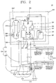
- a multi-type air conditioner 20 includes indoor units 210, an outdoor unit 220, and a liquid-stay preventing device including an evaporation accelerating unit 310 and an operation unit 320 in order to accelerate the evaporation of a liquefied refrigerant flowing from the indoor unit 210.
- a plurality of indoor units 210 are disposed in a room, each of which includes an indoor heat exchanger 211 and an indoor expansion unit 213 disposed at one side of the indoor heat exchanger 211.
- the outdoor unit 220 includes a plurality of compressors 221 compressing a refrigerant, a four-way valve 222 disposed at a discharge side of the compressor 221 and switching a flow path of the refrigerant, a plurality of outdoor heat exchangers 223 connected to the four-way valve 222, in which the refrigerant undergoes heat exchange, and an accumulator 224 connected to a suction side of each compressor 221 to allow a gaseous refrigerant to be sucked into each compressor 221.
- a pair of compressors 221 are connected together by a flow pipe 225 so that oil can flow therebetween, and an oil separator 226 is installed at a discharge side of each compressor 221.
- An oil return path 227 is provided at one side of each oil separator 226 in order to allow the separated oil to return to each compressor 221. Also, a first check valve 228 for preventing a back flow of the refrigerant is installed at a discharge side of each oil separator 226.
- a second check valve 228' and an outdoor expansion unit 229 are provided at an outlet of each outdoor heat exchanger 223 along a direction that the refrigerant flows at the time of cooling operation, and a receiver 230 is provided at downside of the second check valve 228' and the outdoor expansion unit 229.
- Service valves are respectively installed at a downside of the receiver 230 and a connection pipe 231 of the indoor unit 210.
- the evaporation accelerating unit 310 includes a tank body 311, a heat exchange part 313 and connection pipes 315.
- the tank body 311 is a container for temporarily keeping a refrigerant and is disposed at a lower level of a building where a height difference with the outdoor unit 220 is great.
- the heat exchange part 313 is installed inside the tank body 313 and evaporates by heating, the liquefied refrigerant accumulated therein. More specifically, the heat exchange part 313 includes a pipe through which a refrigerant discharged from the compressor 221 can flow.
- connection pipes 315 include a first connection pipe 315a, a second connection pipe 315b, a third connection pipe 315c, a fourth connection pipe 315d and a fifth connection pipe 315e.
- the first connection pipe 315a connects the heat exchange part 313 to a discharge side of the compressor 221.
- the second connection pipe 315b connects the heat exchange part 313 to the receiver 230.
- the third connection pipe 315c connects the heat exchange part 313 to the outdoor heat exchanger 223 to allow the evaporated refrigerant to be introduced to the outdoor heat exchanger 223 along a direction that the refrigerant flows at the time of cooling operation.
- a check valve 228" is installed on the third connection pipe 315c so as to prevent the refrigerant having been discharged from the compressor 221 from being introduced into the tank body 311.
- connection pipe 315d its one side is connected to an outlet of the indoor unit 210 along the direction that the refrigerant flows at the time of cooling, and its other side is connected to the tank body 311, so that the refrigerant can be introduced into the tank body 311.
- connection pipe 315e its one side is connected to an inlet of the outdoor unit 220, and its other side is connected to the tank body 311, so that the refrigerant within the tank body 311 can flow out.
- the operation unit 320 includes a liquefied refrigerant level detecting sensor 321, a hot gas opening/closing valve 323 and a controller 325.
- the liquefied refrigerant level detecting sensor 321 is installed within the tank body 311, detects a level of the liquefied refrigerant and sends a signal to the controller 321 when the level is the same as or higher than a certain level.
- the hot gas opening/closing valve 323 is installed on the first connection pipe 315a, and is opened or closed so as to allow the refrigerant discharged from the compressor 221 to flow to the heat exchange part 313 or prevent the flowing to the heat exchange part 313.
- the controller 325 is implemented as a micom type provided with a control program, and determines and indicates whether to open or close the hot gas opening/closing valve 323 upon receiving a signal of the liquefied refrigerant level detecting sensor 321.
- the liquefied refrigerant level detecting sensor 321 sends a signal to the controller 325 when the level of the liquefied refrigerant within the tank body 311 reaches a set level.
- the controller 325 opens the hot gas opening/closing valve 323 upon receiving the signal, thereby allowing the refrigerant having been discharged from the compressor 221 to flow to the heat exchange part 313.
- the liquefied refrigerant within the tank body 311 absorbs latent heat and is evaporated. Accordingly, the refrigerant is not accumulated at a low pressure side.
- the refrigerant having undergone heat-release and condensation in the heat exchange part 313 is introduced into the receiver 230 along the second connection pipe 315b, joins the refrigerant having flowed out from the outdoor heat exchanger 233, and flows to the indoor unit 210.
- the controller 325 closes the hot gas opening/closing valve 323 to prevent the refrigerant discharged from the compressor 221 from flowing to the heat exchange part 313.
- a multi-type air conditioner in accordance with the second embodiment will now be described with reference Figures 4 and 5.
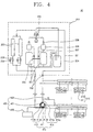
- the multi-type air conditioner 40 includes an indoor unit 210, an outdoor unit 220 and a liquid-stay preventing device including an evaporation accelerating unit 410 and an operation unit 420 for accelerating the evaporation of a liquefied refrigerant flowing from the indoor unit.
- the evaporation accelerating unit 410 includes a tank body 411, a heat exchange part 413 and connection pipes 415.
- the tank body 411 is a container for temporarily keeping a refrigerant.
- the heat exchange part 413 heats a liquefied refrigerant accumulated in the tank body 311.
- the heat exchange part 413 of the second embodiment includes a heat transfer fin 413a and an electric heater 413b.
- the electric heater 413b is preferably provided as an auxiliary unit in order to improve heating efficiency.
- the heat transfer fin 413a and the electric heater 413b may be applied to the first embodiment as a modification thereof.
- the heat transfer fin 413a protrudes from an outer surface of the tank body 411 with a maximum sectional area so that the refrigerant within the tank body 411 absorbs exterior latent heat and thusly be evaporated.
- the electric heater 413b is installed inside the tank body 411 and evaporates the liquefied refrigerant therein by heating.
- connection pipes 415 include an inflow pipe 415a, an outflow pipe 415b and a bypass flow path 415c.
- One side of the inflow pipe 415 is connected to an outlet of the indoor unit 210 along a direction that a refrigerant flows at the time of cooling operation, and its other side is connected to the tank body 411, so that the refrigerant can be introduced into the tank body 411.
- the outflow pipe 415b connects the tank body 411 to an inlet side of the outdoor unit 200 so that the refrigerant within the tank body 411 can flow out.
- bypass flow path 415c One side of the bypass flow path 415c is connected to the inflow pipe 415a, and its other side is connected to the outflow pipe 415b, so that the bypass flow path 415c allows the refrigerant flowing from the indoor unit 210 to the outdoor unit 220 to bypass the tank body 411.
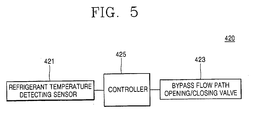
- the operation unit includes a refrigerant temperature detecting sensor 421, a bypass flow path opening/closing valve 423 and a controller 425.
- the refrigerant temperature detecting sensor 421 is installed within the tank body 411, detects a temperature of a refrigerant, and sends a signal to the controller 425 when the detected temperature is the same as or higher than a certain temperature.
- the bypass flow path opening/closing valve 423 is installed on the bypass flow path 415c and is opened or closed so as to open or close the bypass flow path 415c.
- the controller 425 is implemented in a micom type provided with a control program, and determines and indicates whether to open or close the bypass flow path opening/closing valve 423 upon receiving a signal of the refrigerant temperature detecting sensor 421.
- the refrigerant temperature detecting sensor 421 detects a temperature inside the tank body 81 and sends a signal to the controller 425 when the temperature of a refrigerant sucked to a compressor 221 is excessively high.
- the controller 425 opens the bypass flow path opening/closing valve 423 to make a refrigerant of the indoor unit 210 flow to the outdoor unit 220 along the bypass flow path 415c.
- the controller 91 closes the bypass flow path opening/closing valve 423.
- the refrigerant is introduced into the tank body 411 and is evaporated by absorbing latent heat transferred through the heat transfer fin 413a.
- the refrigerant is not accumulated at a low pressure side.
- the controller 425 When a temperature at which a liquefied refrigerant in the tank body 411 is excessively generated due to a relatively-low temperature of the ambient air is detected, the controller 425 operates the electric heater 413b to accelerate the evaporation of the liquefied refrigerant.
- a liquefied refrigerant is not accumulated in an indoor unit and a connection pipe, which are a low pressure side where the pressure is relatively low, but smoothly passes therethrough regardless of a height difference between the indoor unit and the outdoor unit. Therefore, the efficiency of the multi-type air conditioner is improved.
- the reliability of the cooling operation is improved, and the liquefied refrigerant accumulated at the low pressure side is introduced into a compressor of the outdoor unit, thereby preventing damage to the compressor.
Applications Claiming Priority (1)
| Application Number | Priority Date | Filing Date | Title |
|---|---|---|---|
| KR1020040088949A KR100631545B1 (ko) | 2004-11-03 | 2004-11-03 | 증발탱크를 구비한 멀티형 공기조화기 |
Publications (3)
| Publication Number | Publication Date |
|---|---|
| EP1655554A2 true EP1655554A2 (fr) | 2006-05-10 |
| EP1655554A3 EP1655554A3 (fr) | 2011-08-24 |
| EP1655554B1 EP1655554B1 (fr) | 2016-07-20 |
Family
ID=35840347
Family Applications (1)
| Application Number | Title | Priority Date | Filing Date |
|---|---|---|---|
| EP05256656.9A Expired - Fee Related EP1655554B1 (fr) | 2004-11-03 | 2005-10-27 | Air conditionné multi-types |
Country Status (5)
| Country | Link |
|---|---|
| US (1) | US7624590B2 (fr) |
| EP (1) | EP1655554B1 (fr) |
| KR (1) | KR100631545B1 (fr) |
| CN (1) | CN1769814A (fr) |
| ES (1) | ES2588684T3 (fr) |
Cited By (2)
| Publication number | Priority date | Publication date | Assignee | Title |
|---|---|---|---|---|
| CN101231019B (zh) * | 2007-01-26 | 2012-07-04 | Lg电子株式会社 | 用于控制复式空调需求的系统和方法 |
| WO2016146858A1 (fr) * | 2015-03-13 | 2016-09-22 | Eurl S.P.S. | Dispositif thermodynamique reversible de transfert de chaleur |
Families Citing this family (4)
| Publication number | Priority date | Publication date | Assignee | Title |
|---|---|---|---|---|
| JP4258553B2 (ja) * | 2007-01-31 | 2009-04-30 | ダイキン工業株式会社 | 熱源ユニット及び冷凍装置 |
| KR101532781B1 (ko) * | 2008-08-27 | 2015-07-01 | 엘지전자 주식회사 | 공기조화시스템 |
| KR20100062115A (ko) * | 2008-12-01 | 2010-06-10 | 삼성전자주식회사 | 공기조화기 및 그 제어방법 |
| TWI521140B (zh) * | 2012-04-20 | 2016-02-11 | 財團法人工業技術研究院 | 數據機房之無油離心式冷卻系統 |
Citations (4)
| Publication number | Priority date | Publication date | Assignee | Title |
|---|---|---|---|---|
| JPH01174869A (ja) * | 1987-12-28 | 1989-07-11 | Daikin Ind Ltd | 冷凍装置 |
| EP0779481A2 (fr) * | 1995-12-15 | 1997-06-18 | Showa Aluminum Corporation | Système à circuit frigorifique |
| JP2000179992A (ja) * | 1998-12-16 | 2000-06-30 | Sanyo Electric Co Ltd | 空調装置 |
| US20020026807A1 (en) * | 2000-08-31 | 2002-03-07 | Minister David J. | Refrigeration systems |
Family Cites Families (22)
| Publication number | Priority date | Publication date | Assignee | Title |
|---|---|---|---|---|
| US2472729A (en) * | 1940-04-11 | 1949-06-07 | Outboard Marine & Mfg Co | Refrigeration system |
| US3065610A (en) * | 1960-08-09 | 1962-11-27 | Stewart Warner Corp | Charge stabilizer for heat pump |
| US3783841A (en) * | 1971-10-04 | 1974-01-08 | Ethyl Corp | Fuel system |
| AT325644B (de) * | 1973-10-11 | 1975-10-27 | Bosch Hausgeraete Gmbh | Kühlmöbel, insbesondere zweitemperaturen-kühlschrank |
| US3955375A (en) * | 1974-08-14 | 1976-05-11 | Virginia Chemicals Inc. | Combination liquid trapping suction accumulator and evaporator pressure regulator device including a capillary cartridge and heat exchanger |
| US4030315A (en) * | 1975-09-02 | 1977-06-21 | Borg-Warner Corporation | Reverse cycle heat pump |
| US4217765A (en) * | 1979-06-04 | 1980-08-19 | Atlantic Richfield Company | Heat exchanger-accumulator |
| US4488413A (en) * | 1983-01-17 | 1984-12-18 | Edward Bottum | Suction accumulator structure |
| US4718250A (en) * | 1986-07-07 | 1988-01-12 | James Warren | Compact heat exchanger for refrigeration systems |
| US5878810A (en) * | 1990-11-28 | 1999-03-09 | Kabushiki Kaisha Toshiba | Air-conditioning apparatus |
| US5245833A (en) * | 1992-05-19 | 1993-09-21 | Martin Marietta Energy Systems, Inc. | Liquid over-feeding air conditioning system and method |
| US5233842A (en) * | 1992-07-01 | 1993-08-10 | Thermo King Corporation | Accumulator for refrigeration system |
| JPH07120092A (ja) | 1993-10-20 | 1995-05-12 | Fujitsu General Ltd | 空気調和機 |
| US5622055A (en) * | 1995-03-22 | 1997-04-22 | Martin Marietta Energy Systems, Inc. | Liquid over-feeding refrigeration system and method with integrated accumulator-expander-heat exchanger |
| US6047557A (en) * | 1995-06-07 | 2000-04-11 | Copeland Corporation | Adaptive control for a refrigeration system using pulse width modulated duty cycle scroll compressor |
| US6276158B1 (en) * | 1998-07-23 | 2001-08-21 | Eaton-Williams Group Limited | Heat exchange equipment |
| US6220050B1 (en) * | 1998-11-24 | 2001-04-24 | Tecumseh Products Company | Suction accumulator |
| JP3815302B2 (ja) * | 2001-11-12 | 2006-08-30 | 株式会社デンソー | 車両用空調装置 |
| US6910341B2 (en) * | 2003-09-26 | 2005-06-28 | Thermo King Corporation | Temperature control apparatus and method of operating the same |
| US7299649B2 (en) * | 2003-12-09 | 2007-11-27 | Emerson Climate Technologies, Inc. | Vapor injection system |
| JP2005265381A (ja) * | 2004-03-22 | 2005-09-29 | Sanyo Electric Co Ltd | 冷媒サイクル装置 |
| KR100569833B1 (ko) * | 2005-01-07 | 2006-04-11 | 한국에너지기술연구원 | 냉온열제조시스템을 갖는 2단 압축 히트펌프 시스템의플래시탱크 |
-
2004
- 2004-11-03 KR KR1020040088949A patent/KR100631545B1/ko not_active IP Right Cessation
-
2005
- 2005-10-21 US US11/254,664 patent/US7624590B2/en active Active
- 2005-10-27 EP EP05256656.9A patent/EP1655554B1/fr not_active Expired - Fee Related
- 2005-10-27 ES ES05256656.9T patent/ES2588684T3/es active Active
- 2005-11-01 CN CNA2005101186511A patent/CN1769814A/zh active Pending
Patent Citations (4)
| Publication number | Priority date | Publication date | Assignee | Title |
|---|---|---|---|---|
| JPH01174869A (ja) * | 1987-12-28 | 1989-07-11 | Daikin Ind Ltd | 冷凍装置 |
| EP0779481A2 (fr) * | 1995-12-15 | 1997-06-18 | Showa Aluminum Corporation | Système à circuit frigorifique |
| JP2000179992A (ja) * | 1998-12-16 | 2000-06-30 | Sanyo Electric Co Ltd | 空調装置 |
| US20020026807A1 (en) * | 2000-08-31 | 2002-03-07 | Minister David J. | Refrigeration systems |
Cited By (2)
| Publication number | Priority date | Publication date | Assignee | Title |
|---|---|---|---|---|
| CN101231019B (zh) * | 2007-01-26 | 2012-07-04 | Lg电子株式会社 | 用于控制复式空调需求的系统和方法 |
| WO2016146858A1 (fr) * | 2015-03-13 | 2016-09-22 | Eurl S.P.S. | Dispositif thermodynamique reversible de transfert de chaleur |
Also Published As
| Publication number | Publication date |
|---|---|
| ES2588684T3 (es) | 2016-11-04 |
| CN1769814A (zh) | 2006-05-10 |
| KR100631545B1 (ko) | 2006-10-09 |
| US7624590B2 (en) | 2009-12-01 |
| KR20060039740A (ko) | 2006-05-09 |
| EP1655554B1 (fr) | 2016-07-20 |
| EP1655554A3 (fr) | 2011-08-24 |
| US20060090486A1 (en) | 2006-05-04 |
Similar Documents
| Publication | Publication Date | Title |
|---|---|---|
| JP3925545B2 (ja) | 冷凍装置 | |
| EP2083230B1 (fr) | Système de climatisation | |
| JP4497234B2 (ja) | 空気調和装置 | |
| JP6091399B2 (ja) | 空気調和装置 | |
| EP1801520B1 (fr) | Système de conditionnement d'air | |
| JP5414482B2 (ja) | 空気調和機 | |
| EP2869002B1 (fr) | Climatiseur et procédé de commande correspondant | |
| US9151522B2 (en) | Air conditioner and control method thereof | |
| EP2075519B1 (fr) | Système de climatisation | |
| EP1655555A2 (fr) | Conditionneur d'air | |
| EP1655554B1 (fr) | Air conditionné multi-types | |
| JP6277005B2 (ja) | 冷凍装置 | |
| JP5308205B2 (ja) | 空気調和機 | |
| KR101414860B1 (ko) | 공기 조화기 및 그의 제어방법 | |
| JP5133524B2 (ja) | 空気調和装置 | |
| EP1701114B1 (fr) | Dispositif de conditionnement d'air | |
| JPH04324069A (ja) | 冷凍装置 | |
| JP5765278B2 (ja) | 室外マルチ型空気調和装置 | |
| WO2015053168A1 (fr) | Dispositif frigorifique | |
| CN114543185B (zh) | 一种空调系统 | |
| KR101404105B1 (ko) | 공기조화기 | |
| JP2002147878A (ja) | ヒートポンプ装置 | |
| CN115751466A (zh) | 一种空调系统 | |
| JP2024034631A (ja) | 空気調和装置 | |
| AU2014335574C1 (en) | Air-conditioning apparatus |
Legal Events
| Date | Code | Title | Description |
|---|---|---|---|
| PUAI | Public reference made under article 153(3) epc to a published international application that has entered the european phase |
Free format text: ORIGINAL CODE: 0009012 |
|
| 17P | Request for examination filed |
Effective date: 20051108 |
|
| AK | Designated contracting states |
Kind code of ref document: A2 Designated state(s): AT BE BG CH CY CZ DE DK EE ES FI FR GB GR HU IE IS IT LI LT LU LV MC NL PL PT RO SE SI SK TR |
|
| AX | Request for extension of the european patent |
Extension state: AL BA HR MK YU |
|
| PUAL | Search report despatched |
Free format text: ORIGINAL CODE: 0009013 |
|
| AK | Designated contracting states |
Kind code of ref document: A3 Designated state(s): AT BE BG CH CY CZ DE DK EE ES FI FR GB GR HU IE IS IT LI LT LU LV MC NL PL PT RO SE SI SK TR |
|
| AX | Request for extension of the european patent |
Extension state: AL BA HR MK YU |
|
| RIC1 | Information provided on ipc code assigned before grant |
Ipc: F25B 13/00 20060101AFI20110719BHEP |
|
| AKX | Designation fees paid |
Designated state(s): ES FR IT NL |
|
| REG | Reference to a national code |
Ref country code: DE Ref legal event code: R108 Effective date: 20120502 |
|
| 17Q | First examination report despatched |
Effective date: 20150508 |
|
| GRAP | Despatch of communication of intention to grant a patent |
Free format text: ORIGINAL CODE: EPIDOSNIGR1 |
|
| INTG | Intention to grant announced |
Effective date: 20160126 |
|
| GRAS | Grant fee paid |
Free format text: ORIGINAL CODE: EPIDOSNIGR3 |
|
| GRAA | (expected) grant |
Free format text: ORIGINAL CODE: 0009210 |
|
| AK | Designated contracting states |
Kind code of ref document: B1 Designated state(s): ES FR IT NL |
|
| REG | Reference to a national code |
Ref country code: FR Ref legal event code: PLFP Year of fee payment: 12 |
|
| REG | Reference to a national code |
Ref country code: ES Ref legal event code: FG2A Ref document number: 2588684 Country of ref document: ES Kind code of ref document: T3 Effective date: 20161104 |
|
| REG | Reference to a national code |
Ref country code: NL Ref legal event code: MP Effective date: 20160720 |
|
| PG25 | Lapsed in a contracting state [announced via postgrant information from national office to epo] |
Ref country code: NL Free format text: LAPSE BECAUSE OF FAILURE TO SUBMIT A TRANSLATION OF THE DESCRIPTION OR TO PAY THE FEE WITHIN THE PRESCRIBED TIME-LIMIT Effective date: 20160720 |
|
| PLBE | No opposition filed within time limit |
Free format text: ORIGINAL CODE: 0009261 |
|
| STAA | Information on the status of an ep patent application or granted ep patent |
Free format text: STATUS: NO OPPOSITION FILED WITHIN TIME LIMIT |
|
| 26N | No opposition filed |
Effective date: 20170421 |
|
| REG | Reference to a national code |
Ref country code: FR Ref legal event code: PLFP Year of fee payment: 13 |
|
| REG | Reference to a national code |
Ref country code: FR Ref legal event code: PLFP Year of fee payment: 14 |
|
| PGFP | Annual fee paid to national office [announced via postgrant information from national office to epo] |
Ref country code: FR Payment date: 20190906 Year of fee payment: 15 |
|
| PGFP | Annual fee paid to national office [announced via postgrant information from national office to epo] |
Ref country code: IT Payment date: 20191016 Year of fee payment: 15 Ref country code: ES Payment date: 20191105 Year of fee payment: 15 |
|
| PG25 | Lapsed in a contracting state [announced via postgrant information from national office to epo] |
Ref country code: FR Free format text: LAPSE BECAUSE OF NON-PAYMENT OF DUE FEES Effective date: 20201031 |
|
| PG25 | Lapsed in a contracting state [announced via postgrant information from national office to epo] |
Ref country code: IT Free format text: LAPSE BECAUSE OF NON-PAYMENT OF DUE FEES Effective date: 20201027 |
|
| REG | Reference to a national code |
Ref country code: ES Ref legal event code: FD2A Effective date: 20220128 |
|
| PG25 | Lapsed in a contracting state [announced via postgrant information from national office to epo] |
Ref country code: ES Free format text: LAPSE BECAUSE OF NON-PAYMENT OF DUE FEES Effective date: 20201028 |