EP1655412A2 - Drainelement mit Expansionszonen - Google Patents
Drainelement mit Expansionszonen Download PDFInfo
- Publication number
- EP1655412A2 EP1655412A2 EP05024157A EP05024157A EP1655412A2 EP 1655412 A2 EP1655412 A2 EP 1655412A2 EP 05024157 A EP05024157 A EP 05024157A EP 05024157 A EP05024157 A EP 05024157A EP 1655412 A2 EP1655412 A2 EP 1655412A2
- Authority
- EP
- European Patent Office
- Prior art keywords
- drainage member
- base portion
- drainage
- expansion zones
- expansion
- Prior art date
- Legal status (The legal status is an assumption and is not a legal conclusion. Google has not performed a legal analysis and makes no representation as to the accuracy of the status listed.)
- Granted
Links
Images



Classifications
-
- E—FIXED CONSTRUCTIONS
- E02—HYDRAULIC ENGINEERING; FOUNDATIONS; SOIL SHIFTING
- E02B—HYDRAULIC ENGINEERING
- E02B11/00—Drainage of soil, e.g. for agricultural purposes
- E02B11/005—Drainage conduits
-
- E—FIXED CONSTRUCTIONS
- E01—CONSTRUCTION OF ROADS, RAILWAYS, OR BRIDGES
- E01C—CONSTRUCTION OF, OR SURFACES FOR, ROADS, SPORTS GROUNDS, OR THE LIKE; MACHINES OR AUXILIARY TOOLS FOR CONSTRUCTION OR REPAIR
- E01C13/00—Pavings or foundations specially adapted for playgrounds or sports grounds; Drainage, irrigation or heating of sports grounds
- E01C13/02—Foundations, e.g. with drainage or heating arrangements
Definitions
- the present invention relates generally to systems for draining water away from a generally flat substrate, and more particularly to a drainage member that is designed to be located beneath an upper layer of material, such as artificial turf, synthetic turf or the like, for draining away water that seeps through such upper layer.
- a drainage member that is designed to be located beneath an upper layer of material, such as artificial turf, synthetic turf or the like, for draining away water that seeps through such upper layer.
- a drainage member is provided that is considerably less expensive than known drainage systems, and avoids the problem of undue expansion of the drainage member.
- the present invention includes a drainage member for use in promoting the drainage of water away from a substrate positioned adjacent to the drainage member.
- the drainage member includes an elongated, longitudinally extending base formed of a flexible material and having a plurality of outwardly extending projections, with the projections being spaced from one another to form drainage channels between the projections.
- the elongated base has a plurality of expansion zones formed of the flexible material and extending generally transversely of the longitudinal extent thereof, the expansion zones comprising a deformation of the flexible material that absorbs longitudinal expansion of such material when it is exposed to heat without any significant increase in the longitudinal length of the drainage member.
- the deformation of the flexible material may be caused by forming one or more u-shaped grooves extending generally transversely to the longitudinal extent of the base portion.
- the deformation may be caused by a plurality of holes or slots penetrating the base portion and extending along a line that is generally transverse to the longitudinal extent of the base portion.
- the deformation is caused by reducing the thickness of the flexible material forming the base portion along a width that is generally transverse to the longitudinal extent of the base portion.
- the projections of drainage member are generally cone shaped and extend perpendicularly away from the base portion, and the extending ends of the projections are flat for supporting a substrate thereon.
- the present invention also includes a method of forming a drainage member comprising the steps of providing a longitudinally extending flat base portion formed of flexible material; deforming the base portion to create a plurality of projections extending away from the flat base portion in spaced relation to one another to form drainage channels between the projections; and deforming the base portion to form expansion zones extending generally transversely of the longitudinal extent of the base portion so that the expansion zones will absorb longitudinal expansion of such material when it is exposed to heat without any significant increase in the longitudinal length of the drainage member.
- the step of deforming the base portion to form expansion zones may include deforming the base portion into one or more v-shaped grooves extending transversely to the longitudinal extent of the base portion; or creating a plurality of holes or slots penetrating the base portion and extending along a line that is generally transverse to the longitudinal extent of the base portion; or reducing the thickness of the base portion along a width that is generally transverse to the longitudinal extent of the base portion.
- Fig. 1 is a diagrammatic view illustrating one typical artificial turf system in which the drainage member of the present invention is utilized;
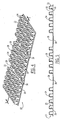
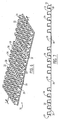
- Fig. 2 is a perspective view of one embodiment of the drainage member of the present invention.
- Fig. 3 is an end view of the drainage member illustrated in Fig. 2;
- Fig. 4 is a perspective view of another embodiment of the drainage member of the present invention.
- Fig. 5 is a section view of the drainage member illustrated in Fig. 4 taken along line 5-5;
- Fig. 6 is a perspective view of yet another embodiment of the drainage member of the present invention.
- Fig. 7 is a section view of the drainage member illustrated in Fig. 6 taken along line 7-7;
- Fig. 8 is a perspective view of another embodiment of the drainage member of the present invention.
- Fig. 9 is a section view of the drainage member illustrated in Fig. 8 taken along line 9-9.
- FIG. 1 illustrates a typical environment in which a drainage member 10 according to the present invention is utilized. More specifically, Fig. 1 illustrates an artificial turf system which includes a foundation 12 which may be composed of virtually any type of firm material, and the drainage member 10 is supported on top of the foundation 12. Artificial grass or turf 14 is supported on top of the drainage member 10 so that the water collecting on or within the artificial turf 14 will penetrate the bottom layer 16 of the artificial turf and flow into the open areas or drainage channels 18 of the drainage member 10, as will be described in greater detail below. The water which collects in the drainage member 10 is channeled so that it will flow away from the artificial turf through a conventional water discharge conduit or the like (not shown) in a manner that is well known in the art.
- a conventional water discharge conduit or the like not shown
- Fig. 1 the environment for the present invention which is illustrated in Fig. 1 is just one of a wide variety of applications in which the drainage member 10 can be utilized.
- the drainage member 10 could be used under paving stones, or loose bricks and the like.
- the drainage member 10 includes a general horizontally extending base portion 20 that is formed of a flexible material which is preferably polystyrene, but which may be formed of any equivalent flexible material.
- the base portion 20 is deformed to create a large number of projections 22 that are spaced from one another to form the drainage channels 18 between the projections 22.
- the base 20 is also deformed into one or more grooves 26 that generally have an inverted u-shaped configuration in cross-section as best illustrated in Fig. 3, and that extend generally transversely to the longitudinal extent of the base portion 20.
- These grooves 26 are configured and spaced from one another so that when the drainage member 10 is exposed to heat that would normally cause significant expansion of the drainage member in the direction of its longitudinal extent, the grooves 26 form expansion zones that permit the base portion 20 of the elongated drainage member 10 to expand and retract in the direction of the longitudinal extent of the drainage member 10.
- the expansion zones are designed to absorb the longitudinal expansion of the drainage member 10 so that when the drainage member 10 is exposed to a predetermined amount of heat that would normally result in significant expansion of the drainage member in its longitudinal direction, there will be no significant increase in the longitudinal length of the drainage member 10 as a whole.
- the deformation of the grooves 26 may have configurations other than the inverted u-shaped configuration illustrated in Figs. 2 and 3, provided that the configuration of the grooves 26 is such that they will permit the base portion of the elongated drainage member 10 to expand and retract as described above.
- FIG. 4 and 5 Another embodiment of the drainage member 10 of the present invention is illustrated in Figs. 4 and 5, where like reference numerals are used to identify like components.
- the base portion 20 is deformed to create expansions zones comprised of a plurality of slots 28 that penetrate the base portion 20 and extend along a line that is generally transverse to the longitudinal extent of the base portion 20.
- the size, shape and number of the slots 20 are selected to permit the base portion 20 to expand and retract when exposed to heat as described above, without any significant increase in the longitudinal extent of the drainage member 10.
- a thin strip of sealing material 36 may be secured to drainage member 10 so that it extends along the entire expansion zone formed by the slots 28 to prevent any water from passing therethrough
- the sealing strip can be located below the slots 28 as illustrated in Figs. 4 and 5, or, if desired, it could be located on top of the slots 28 (not shown).
- the thin sealing strip can be made of polystyrene or any other equivalent material that would prevent the penetration of water through the slots 28 with affecting the ability of the slots 28 to carry out their function of absorbing longitudinal expansion of the drainage member 10 as described above.
- the expansion zones consist of a plurality of holes 30 which penetrate the base 20 and extend along a line that is generally transverse to the longitudinal extent of the drainage member 10.
- the size, shape and number of the holes 30 are selected to cause the holes 30 to absorb the longitudinal expansion of the drainage member material when it is exposed to heat without any significant increase in the longitudinal extent of the drainage member 10.
- a sealing strip 36 like that described in connection with the embodiment illustrated in Figs. 4 and 5 could be secured to the drainage member 10 to cover the holes 30 and prevent the flow of water therethrough as described above.
- Figs. 8 and 9 yet another embodiment of the present invention is illustrated in Figs. 8 and 9 where like elements are indicated by like reference numerals.
- the expansion zones are created by deforming the base portion 20 so that it has a reduced thickness along a predetermined width that extends generally transverse to the longitudinal extent of the base portion 20, this reduced thickness portion being indicated by the reference numeral 32 in Figs. 8 and 9.
- the flexible material from which the drainage member 10 is deformed in some way to create the expansion zones that are specifically designed to absorb expansion of the drainage member 10 when it is exposed to a predetermined amount of heat that would otherwise cause significant and undesirable expansion of the drainage member 10 in its longitudinal direction.
- the drainage member 10 can be easily manufactured by starting with a desired flexible material, such as polystyrene or any equivalent flexible material, that has a desired thickness and flexibility, and then deforming this material to create the projections 22 and the expansion zones described above in connection with each of the several embodiments of the present invention.
- the drainage member 10 can be formed in very long lengths sufficient for use in football fields, soccer fields, and the like.
- the drainage member 10 is used in connection with a football field, which has a playing field that is fifty yards wide, it will typically be made into lengths that extend from one side of the artificial turf to the approximate center of the playing field, a length of approximately thirty yards in most cases. Two such lengths of the drainage member 10 would be laid end-to-end to thereby cover the entire width of the artificial turf 14.
- these extending lengths of the drainage member 10 will usually be produced with predetermined widths, and they can easily be installed on top of a foundation 12 (see Fig 1.) with minimal labor and with a small cost of material by installing a number of lengths on top of the foundation 12 to extend longitudinally across the field in side-by-side relationship to cover the entire football field or other area.
- the expansion zones formed in the drainage members in accordance with the several embodiments of the present invention will act to absorb the longitudinal expansion of the materials formed in the drainage member 10 that would otherwise occur without the expansion zones and that could cause undesirable wrinkling or other malfunctions of the supported artificial turf 14, as described above.
- the thickness of the material forming the drainage member 10 will vary depending on many parameters of the particular application of the drainage member 10.
- it is preferably formed of polystyrene and the expansion zones preferably have a width of about one inch, and the expansion zones are spaced from one another about four feet in the longitudinally extending direction of the drainage member 10.
- the projections 22 serve several unique functions in the drainage member 10 of the present invention. They can be made rigid enough to support artificial turf 14 and the like on top of the projections 22 as illustrated in Fig. 1, and at the same time they can be made with sufficient resiliency to absorb some of the shock loads imposed on the artificial turf 14 during use, such as the shock load resulting from a football player falling on the artificial turf 14. In the former regard, it should be noted that the top surfaces 34 of the projection 22 are flat to assist in supporting the artificial turf 14 or the like on.
- the shock absorbing advantage offered by the drainage member 10 of the present invention provides a substantial improvement over the known prior art arrangements discussed above in which a thick layer of sand or small loose particles is placed directly below the artificial turf and offers virtually no ability to absorb shock loads.
Landscapes
- Engineering & Computer Science (AREA)
- Structural Engineering (AREA)
- General Engineering & Computer Science (AREA)
- Civil Engineering (AREA)
- Agronomy & Crop Science (AREA)
- Mechanical Engineering (AREA)
- Life Sciences & Earth Sciences (AREA)
- Architecture (AREA)
- Road Paving Structures (AREA)
- Pit Excavations, Shoring, Fill Or Stabilisation Of Slopes (AREA)
- Lining And Supports For Tunnels (AREA)
- Microwave Amplifiers (AREA)
- Thin Film Transistor (AREA)
- Bipolar Transistors (AREA)
Applications Claiming Priority (1)
| Application Number | Priority Date | Filing Date | Title |
|---|---|---|---|
| US10/984,580 US7014390B1 (en) | 2004-11-09 | 2004-11-09 | Drainage member with expansion zones |
Publications (3)
| Publication Number | Publication Date |
|---|---|
| EP1655412A2 true EP1655412A2 (de) | 2006-05-10 |
| EP1655412A3 EP1655412A3 (de) | 2007-05-02 |
| EP1655412B1 EP1655412B1 (de) | 2008-12-31 |
Family
ID=35511127
Family Applications (1)
| Application Number | Title | Priority Date | Filing Date |
|---|---|---|---|
| EP05024157A Expired - Lifetime EP1655412B1 (de) | 2004-11-09 | 2005-11-05 | Drainelement mit Expansionszonen |
Country Status (7)
| Country | Link |
|---|---|
| US (1) | US7014390B1 (de) |
| EP (1) | EP1655412B1 (de) |
| CN (1) | CN1776100B (de) |
| AT (1) | ATE419429T1 (de) |
| CA (1) | CA2525638C (de) |
| DE (1) | DE602005012040D1 (de) |
| ES (1) | ES2319205T3 (de) |
Families Citing this family (40)
| Publication number | Priority date | Publication date | Assignee | Title |
|---|---|---|---|---|
| WO2005078211A1 (en) * | 2004-02-13 | 2005-08-25 | Elevated Landscape Technologies | Green roofing apparatus, system and method |
| US7565779B2 (en) * | 2005-02-25 | 2009-07-28 | W. R. Grace & Co.-Conn. | Device for in-situ barrier |
| US7399145B2 (en) * | 2005-07-25 | 2008-07-15 | Clark Kevin L | Multi-layer liner assembly for a sand trap |
| ATE422221T1 (de) * | 2005-12-23 | 2009-02-15 | Mondo Spa | Kunstrasen und verfahren für dessen verlegung |
| US7699562B2 (en) * | 2006-05-31 | 2010-04-20 | Clark Kevin L | Liner assembly for a sand trap |
| US20070283653A1 (en) * | 2006-06-08 | 2007-12-13 | Gregory Garner | Green roofing system including dimpled anchor layer |
| US8740141B2 (en) * | 2006-10-23 | 2014-06-03 | Tarkett Inc. | Aircraft arrestor system and method of decelerating an aircraft |
| ES2674721T3 (es) | 2007-01-19 | 2018-07-03 | Brock International | Base para un sistema de césped |
| US8353640B2 (en) * | 2008-01-22 | 2013-01-15 | Brock Usa, Llc | Load supporting panel having impact absorbing structure |
| FR2913988B1 (fr) * | 2007-03-23 | 2010-11-05 | Creativ Synthetique Sarl | Dalle de pelouse synthetique. |
| NL1034221C2 (nl) * | 2007-08-02 | 2009-02-03 | Sekisui Alveo Ag | Kunstgrasveldsysteem in het bijzonder geschikt voor sportvelden, voorzien van een sporttechnische laag, alsmede een dergelijke sporttechnische laag. |
| US20090269517A1 (en) * | 2008-04-29 | 2009-10-29 | Kenneth Alan Karmie | Floor cleansing system and method for use thereof |
| US7993729B2 (en) * | 2008-10-27 | 2011-08-09 | Ronald Wise | Substrate for artificial turf |
| USD637318S1 (en) | 2009-01-30 | 2011-05-03 | Steven Lee Sawyer | Turf underlayment |
| US20100239790A1 (en) * | 2009-03-19 | 2010-09-23 | Stricklen Phillip M | System and method for an improved artificial turf |
| EP2452017B1 (de) | 2009-07-06 | 2017-12-27 | Brock International | Strukturelles unterlagensystem für pflasterungs- und bodenbelagselemente |
| US8162567B2 (en) * | 2010-04-20 | 2012-04-24 | Polyguard Products, Inc. | Water retention cell structures |
| NL1038031C2 (nl) * | 2010-06-11 | 2011-12-19 | Spekpannekoek B V | Kunstgras sportveld. |
| USD645169S1 (en) | 2010-11-24 | 2011-09-13 | Brock Usa, Llc | Paver base underlayment |
| US8672584B2 (en) | 2011-05-13 | 2014-03-18 | Rapac | Drainage beads |
| US9194086B1 (en) | 2012-01-16 | 2015-11-24 | Dale Karmie | System and method for absorbing shocks impacts while providing water drainage |
| FR2989306A1 (fr) * | 2012-04-16 | 2013-10-18 | Ryb Sa | Structure geosynthetique multi-fonction |
| US9986693B2 (en) | 2012-07-05 | 2018-06-05 | Permavoid Limited | Plant surface structure and modules and method for forming the same |
| US10238084B2 (en) | 2012-09-07 | 2019-03-26 | Permavoid Limited | Cattle floor |
| PL3117040T3 (pl) | 2014-03-12 | 2019-04-30 | Permavoid Ltd | Konstrukcja sportowego boiska i sposób jego tworzenia |
| US10208434B2 (en) | 2014-03-12 | 2019-02-19 | Permavoid Limited | Sports field structure and method for forming the same |
| US9631328B2 (en) * | 2014-03-12 | 2017-04-25 | Permavoid Limited | Sports field structure and modules and method for forming the same |
| USD866800S1 (en) | 2015-10-26 | 2019-11-12 | Brock Usa, Llc | Turf underlayment |
| US10060082B2 (en) | 2016-05-18 | 2018-08-28 | Brock Usa, Llc | Base for turf system with vertical support extensions at panel edges |
| DE202017101349U1 (de) * | 2017-03-09 | 2018-06-12 | Werner Schlüter | Entkopplungsmatte |
| US10569495B2 (en) * | 2017-05-08 | 2020-02-25 | The Boeing Company | Composite structure assembly having a conformable core |
| IT201700088166A1 (it) * | 2017-08-01 | 2019-02-01 | Maria Giuseppe De | Materassino in materiale plastico impermeabile per sottofondo di manti erbosi sintetici o pavimentazioni e simili. |
| IT201700088145A1 (it) | 2017-08-01 | 2019-02-01 | Maria Giuseppe De | Materassino in materiale plastico impermeabile per sottofondo di manti erbosi sintetici o pavimentazioni e simili. |
| CN107237230A (zh) * | 2017-08-01 | 2017-10-10 | 四川睿铁科技有限责任公司 | 一种膨胀土(岩)路基支挡减胀结构及其施工方法 |
| USD894634S1 (en) | 2018-04-25 | 2020-09-01 | Schluter Systems L.P. | Support mat |
| US10597830B1 (en) | 2018-12-06 | 2020-03-24 | Gerald Lynn Lemons | Apparatus, system, and method for providing drainage of a surface layer |
| CA3165441A1 (en) | 2019-12-23 | 2021-07-01 | SafePlay LLC | Padding layer for athletic field for water retention and drainage |
| WO2021229339A1 (en) * | 2020-05-12 | 2021-11-18 | 4427017 Canada Inc. | Self-cooling artificial turf system with water retention |
| US11306443B2 (en) * | 2020-06-29 | 2022-04-19 | Saudi Arabian Oil Company | Polymer panels for walkway and paving |
| CN114811126B (zh) * | 2022-03-08 | 2024-12-03 | 宁德时代新能源科技股份有限公司 | 用于电池箱体的排水阀、电池、用电装置及排水方法 |
Family Cites Families (20)
| Publication number | Priority date | Publication date | Assignee | Title |
|---|---|---|---|---|
| US3888087A (en) * | 1973-04-11 | 1975-06-10 | Oivind Lorentzen Activities In | Foundation wall protective sheet |
| NO148041C (no) * | 1981-03-11 | 1987-06-10 | Platon As | Beskyttelsesplate, saerlig for grunnmur eller gulv paa grunn |
| US4840515A (en) * | 1986-12-05 | 1989-06-20 | Mirafi, Inc. | Subterranean drain |
| GB2201632B (en) * | 1987-01-21 | 1990-08-22 | Netlon Ltd | Drainage material and drainage core for a drainage system |
| US4943185A (en) * | 1989-03-03 | 1990-07-24 | Mcguckin James P | Combined drainage and waterproofing panel system for subterranean walls |
| US4956951A (en) * | 1989-06-26 | 1990-09-18 | Sealed Air Corporation | Laminated sheet for protecting underground vertical walls |
| NO900235D0 (no) * | 1990-01-16 | 1990-01-16 | Platon As | Beskyttelsesplate for grunnmur eller lignende. |
| CA2098263A1 (en) * | 1993-06-11 | 1994-12-12 | Joseph Clement Brodeur | Earth drains |
| IT230932Y1 (it) * | 1993-07-02 | 1999-07-05 | Tema Tecnologies And Materials | Membrana protettiva impermeabilizzante perfezionata, particolarmente per il rivestimento di muri e pavimentazioni |
| JP3292897B2 (ja) | 1993-10-07 | 2002-06-17 | 大塚化学株式会社 | 人工芝生 |
| CN2245626Y (zh) * | 1995-08-08 | 1997-01-22 | 宋祥顺 | 土壤排水芯板 |
| US5647689A (en) | 1995-12-06 | 1997-07-15 | Abt, Inc. | Drainage channel grates for athletic playing surfaces and associated methods |
| US5976645A (en) | 1998-06-01 | 1999-11-02 | Safturf International Limited | Vertically draining, rubber-filled synthetic turf and method of manufacture |
| US6241421B1 (en) * | 1998-11-06 | 2001-06-05 | Royal Ten Cate (Usa), Inc. | Subterranean drain assembly |
| US6221445B1 (en) | 1999-07-20 | 2001-04-24 | U.S. Greentech, Inc. | Composite artificial turf structure with shock absorption and drainage |
| US6672016B2 (en) * | 2001-03-30 | 2004-01-06 | Lawrence M. Janesky | Wall and sub-floor water drain barrier panel for basement water-control systems |
| CN1429951A (zh) * | 2001-12-29 | 2003-07-16 | 李兰英 | 一种凸起透水板 |
| CN2525123Y (zh) * | 2001-12-30 | 2002-12-11 | 李兰英 | 一种透水板 |
| US6691472B2 (en) * | 2002-02-15 | 2004-02-17 | Theodore G. Hubert | Foundation wall protector |
| US6648550B1 (en) * | 2002-11-12 | 2003-11-18 | Alton F. Parker | Subterranean drainage device |
-
2004
- 2004-11-09 US US10/984,580 patent/US7014390B1/en not_active Expired - Lifetime
-
2005
- 2005-11-05 AT AT05024157T patent/ATE419429T1/de not_active IP Right Cessation
- 2005-11-05 ES ES05024157T patent/ES2319205T3/es not_active Expired - Lifetime
- 2005-11-05 EP EP05024157A patent/EP1655412B1/de not_active Expired - Lifetime
- 2005-11-05 DE DE602005012040T patent/DE602005012040D1/de not_active Expired - Lifetime
- 2005-11-07 CA CA002525638A patent/CA2525638C/en not_active Expired - Lifetime
- 2005-11-08 CN CN2005101315654A patent/CN1776100B/zh not_active Expired - Lifetime
Also Published As
| Publication number | Publication date |
|---|---|
| DE602005012040D1 (de) | 2009-02-12 |
| US7014390B1 (en) | 2006-03-21 |
| CA2525638A1 (en) | 2006-05-09 |
| CA2525638C (en) | 2008-11-04 |
| CN1776100A (zh) | 2006-05-24 |
| ES2319205T3 (es) | 2009-05-05 |
| EP1655412B1 (de) | 2008-12-31 |
| EP1655412A3 (de) | 2007-05-02 |
| CN1776100B (zh) | 2010-12-15 |
| ATE419429T1 (de) | 2009-01-15 |
Similar Documents
| Publication | Publication Date | Title |
|---|---|---|
| EP1655412B1 (de) | Drainelement mit Expansionszonen | |
| US6616383B2 (en) | Sediment control barrier | |
| US6877932B2 (en) | Drainage system and method for artificial grass using spacing grid | |
| US4798498A (en) | Device for stabilizing bulk material | |
| US7815395B1 (en) | Subsurface drainage system and drain structure therefor | |
| US3577894A (en) | Playing court | |
| US4444815A (en) | Water permeable ground covering for open spaces | |
| US20040081771A1 (en) | Synthetic sports surface | |
| JPH06104962B2 (ja) | グランドカバー用裏打ちマット及びその製法 | |
| CA2485806C (en) | Landscape/erosion control product | |
| DE2248911A1 (de) | Flaechige bodenentwaesserung mit naturbewuchsmoeglichkeit | |
| JPS58101932A (ja) | 盤状体 | |
| WO2008072073A2 (en) | A synthetic turf mat, a synthetic turf structure including the mat, and a manufacturing method of the mat | |
| US8551602B2 (en) | Sport-technical layer for use in an artificial lawn system, as well as such an artificial lawn system | |
| JP2006037470A (ja) | 集排水板 | |
| CA2393240C (en) | Drainage system and method for artificial grass using spacing grid | |
| US12168855B2 (en) | Removable active panel system | |
| JPH1156135A (ja) | プランターならびにプランターへの灌水パイプの設置方法 | |
| AU620283B1 (en) | Drainage grating | |
| EP1657363B1 (de) | Sport- und/oder Erholungsfläche | |
| JP2003235355A (ja) | 薄層屋上緑化設備 | |
| JP2003219733A (ja) | 薄層緑化設備用仕切材及びそれを用いた薄層緑化設備 | |
| CA2352934A1 (en) | Drainage system for artificial grass using spacing grid | |
| JPS6131045Y2 (de) | ||
| JPH10159315A (ja) | 合成樹脂製マット |
Legal Events
| Date | Code | Title | Description |
|---|---|---|---|
| PUAI | Public reference made under article 153(3) epc to a published international application that has entered the european phase |
Free format text: ORIGINAL CODE: 0009012 |
|
| AK | Designated contracting states |
Kind code of ref document: A2 Designated state(s): AT BE BG CH CY CZ DE DK EE ES FI FR GB GR HU IE IS IT LI LT LU LV MC NL PL PT RO SE SI SK TR |
|
| AX | Request for extension of the european patent |
Extension state: AL BA HR MK YU |
|
| PUAL | Search report despatched |
Free format text: ORIGINAL CODE: 0009013 |
|
| AK | Designated contracting states |
Kind code of ref document: A3 Designated state(s): AT BE BG CH CY CZ DE DK EE ES FI FR GB GR HU IE IS IT LI LT LU LV MC NL PL PT RO SE SI SK TR |
|
| AX | Request for extension of the european patent |
Extension state: AL BA HR MK YU |
|
| 17P | Request for examination filed |
Effective date: 20071026 |
|
| 17Q | First examination report despatched |
Effective date: 20071213 |
|
| AKX | Designation fees paid |
Designated state(s): AT BE BG CH CY CZ DE DK EE ES FI FR GB GR HU IE IS IT LI LT LU LV MC NL PL PT RO SE SI SK TR |
|
| GRAP | Despatch of communication of intention to grant a patent |
Free format text: ORIGINAL CODE: EPIDOSNIGR1 |
|
| GRAS | Grant fee paid |
Free format text: ORIGINAL CODE: EPIDOSNIGR3 |
|
| GRAA | (expected) grant |
Free format text: ORIGINAL CODE: 0009210 |
|
| AK | Designated contracting states |
Kind code of ref document: B1 Designated state(s): AT BE BG CH CY CZ DE DK EE ES FI FR GB GR HU IE IS IT LI LT LU LV MC NL PL PT RO SE SI SK TR |
|
| REG | Reference to a national code |
Ref country code: CH Ref legal event code: EP Ref country code: GB Ref legal event code: FG4D |
|
| REF | Corresponds to: |
Ref document number: 602005012040 Country of ref document: DE Date of ref document: 20090212 Kind code of ref document: P |
|
| REG | Reference to a national code |
Ref country code: IE Ref legal event code: FG4D |
|
| REG | Reference to a national code |
Ref country code: CH Ref legal event code: NV Representative=s name: ZIMMERLI, WAGNER & PARTNER AG |
|
| REG | Reference to a national code |
Ref country code: ES Ref legal event code: FG2A Ref document number: 2319205 Country of ref document: ES Kind code of ref document: T3 |
|
| PG25 | Lapsed in a contracting state [announced via postgrant information from national office to epo] |
Ref country code: FI Free format text: LAPSE BECAUSE OF FAILURE TO SUBMIT A TRANSLATION OF THE DESCRIPTION OR TO PAY THE FEE WITHIN THE PRESCRIBED TIME-LIMIT Effective date: 20081231 Ref country code: PL Free format text: LAPSE BECAUSE OF FAILURE TO SUBMIT A TRANSLATION OF THE DESCRIPTION OR TO PAY THE FEE WITHIN THE PRESCRIBED TIME-LIMIT Effective date: 20081231 Ref country code: LV Free format text: LAPSE BECAUSE OF FAILURE TO SUBMIT A TRANSLATION OF THE DESCRIPTION OR TO PAY THE FEE WITHIN THE PRESCRIBED TIME-LIMIT Effective date: 20081231 Ref country code: SI Free format text: LAPSE BECAUSE OF FAILURE TO SUBMIT A TRANSLATION OF THE DESCRIPTION OR TO PAY THE FEE WITHIN THE PRESCRIBED TIME-LIMIT Effective date: 20081231 |
|
| PG25 | Lapsed in a contracting state [announced via postgrant information from national office to epo] |
Ref country code: EE Free format text: LAPSE BECAUSE OF FAILURE TO SUBMIT A TRANSLATION OF THE DESCRIPTION OR TO PAY THE FEE WITHIN THE PRESCRIBED TIME-LIMIT Effective date: 20081231 Ref country code: RO Free format text: LAPSE BECAUSE OF FAILURE TO SUBMIT A TRANSLATION OF THE DESCRIPTION OR TO PAY THE FEE WITHIN THE PRESCRIBED TIME-LIMIT Effective date: 20081231 Ref country code: LT Free format text: LAPSE BECAUSE OF FAILURE TO SUBMIT A TRANSLATION OF THE DESCRIPTION OR TO PAY THE FEE WITHIN THE PRESCRIBED TIME-LIMIT Effective date: 20081231 |
|
| PG25 | Lapsed in a contracting state [announced via postgrant information from national office to epo] |
Ref country code: IS Free format text: LAPSE BECAUSE OF FAILURE TO SUBMIT A TRANSLATION OF THE DESCRIPTION OR TO PAY THE FEE WITHIN THE PRESCRIBED TIME-LIMIT Effective date: 20090430 Ref country code: PT Free format text: LAPSE BECAUSE OF FAILURE TO SUBMIT A TRANSLATION OF THE DESCRIPTION OR TO PAY THE FEE WITHIN THE PRESCRIBED TIME-LIMIT Effective date: 20090601 Ref country code: CZ Free format text: LAPSE BECAUSE OF FAILURE TO SUBMIT A TRANSLATION OF THE DESCRIPTION OR TO PAY THE FEE WITHIN THE PRESCRIBED TIME-LIMIT Effective date: 20081231 Ref country code: AT Free format text: LAPSE BECAUSE OF FAILURE TO SUBMIT A TRANSLATION OF THE DESCRIPTION OR TO PAY THE FEE WITHIN THE PRESCRIBED TIME-LIMIT Effective date: 20081231 Ref country code: SE Free format text: LAPSE BECAUSE OF FAILURE TO SUBMIT A TRANSLATION OF THE DESCRIPTION OR TO PAY THE FEE WITHIN THE PRESCRIBED TIME-LIMIT Effective date: 20090331 |
|
| PG25 | Lapsed in a contracting state [announced via postgrant information from national office to epo] |
Ref country code: SK Free format text: LAPSE BECAUSE OF FAILURE TO SUBMIT A TRANSLATION OF THE DESCRIPTION OR TO PAY THE FEE WITHIN THE PRESCRIBED TIME-LIMIT Effective date: 20081231 |
|
| PG25 | Lapsed in a contracting state [announced via postgrant information from national office to epo] |
Ref country code: DK Free format text: LAPSE BECAUSE OF FAILURE TO SUBMIT A TRANSLATION OF THE DESCRIPTION OR TO PAY THE FEE WITHIN THE PRESCRIBED TIME-LIMIT Effective date: 20081231 |
|
| PLBE | No opposition filed within time limit |
Free format text: ORIGINAL CODE: 0009261 |
|
| STAA | Information on the status of an ep patent application or granted ep patent |
Free format text: STATUS: NO OPPOSITION FILED WITHIN TIME LIMIT |
|
| REG | Reference to a national code |
Ref country code: CH Ref legal event code: PFA Owner name: AMERICAN WICK DRAIN CORPORATION Free format text: AMERICAN WICK DRAIN CORPORATION#1209 AIRPORT ROAD#MONROE, NC 28110 (US) -TRANSFER TO- AMERICAN WICK DRAIN CORPORATION#1209 AIRPORT ROAD#MONROE, NC 28110 (US) |
|
| 26N | No opposition filed |
Effective date: 20091001 |
|
| PG25 | Lapsed in a contracting state [announced via postgrant information from national office to epo] |
Ref country code: BG Free format text: LAPSE BECAUSE OF FAILURE TO SUBMIT A TRANSLATION OF THE DESCRIPTION OR TO PAY THE FEE WITHIN THE PRESCRIBED TIME-LIMIT Effective date: 20090331 |
|
| PG25 | Lapsed in a contracting state [announced via postgrant information from national office to epo] |
Ref country code: MC Free format text: LAPSE BECAUSE OF NON-PAYMENT OF DUE FEES Effective date: 20091130 |
|
| PGFP | Annual fee paid to national office [announced via postgrant information from national office to epo] |
Ref country code: IE Payment date: 20100413 Year of fee payment: 5 |
|
| PG25 | Lapsed in a contracting state [announced via postgrant information from national office to epo] |
Ref country code: GR Free format text: LAPSE BECAUSE OF FAILURE TO SUBMIT A TRANSLATION OF THE DESCRIPTION OR TO PAY THE FEE WITHIN THE PRESCRIBED TIME-LIMIT Effective date: 20090401 |
|
| PGFP | Annual fee paid to national office [announced via postgrant information from national office to epo] |
Ref country code: DE Payment date: 20101119 Year of fee payment: 6 |
|
| PGFP | Annual fee paid to national office [announced via postgrant information from national office to epo] |
Ref country code: GB Payment date: 20101123 Year of fee payment: 6 Ref country code: IT Payment date: 20101126 Year of fee payment: 6 |
|
| PG25 | Lapsed in a contracting state [announced via postgrant information from national office to epo] |
Ref country code: LU Free format text: LAPSE BECAUSE OF NON-PAYMENT OF DUE FEES Effective date: 20091105 |
|
| PG25 | Lapsed in a contracting state [announced via postgrant information from national office to epo] |
Ref country code: HU Free format text: LAPSE BECAUSE OF FAILURE TO SUBMIT A TRANSLATION OF THE DESCRIPTION OR TO PAY THE FEE WITHIN THE PRESCRIBED TIME-LIMIT Effective date: 20090701 |
|
| PG25 | Lapsed in a contracting state [announced via postgrant information from national office to epo] |
Ref country code: TR Free format text: LAPSE BECAUSE OF FAILURE TO SUBMIT A TRANSLATION OF THE DESCRIPTION OR TO PAY THE FEE WITHIN THE PRESCRIBED TIME-LIMIT Effective date: 20081231 |
|
| PG25 | Lapsed in a contracting state [announced via postgrant information from national office to epo] |
Ref country code: CY Free format text: LAPSE BECAUSE OF FAILURE TO SUBMIT A TRANSLATION OF THE DESCRIPTION OR TO PAY THE FEE WITHIN THE PRESCRIBED TIME-LIMIT Effective date: 20081231 |
|
| PG25 | Lapsed in a contracting state [announced via postgrant information from national office to epo] |
Ref country code: IE Free format text: LAPSE BECAUSE OF NON-PAYMENT OF DUE FEES Effective date: 20101105 |
|
| PGFP | Annual fee paid to national office [announced via postgrant information from national office to epo] |
Ref country code: FR Payment date: 20111125 Year of fee payment: 7 Ref country code: ES Payment date: 20111123 Year of fee payment: 7 Ref country code: CH Payment date: 20111124 Year of fee payment: 7 Ref country code: NL Payment date: 20111123 Year of fee payment: 7 |
|
| PGFP | Annual fee paid to national office [announced via postgrant information from national office to epo] |
Ref country code: BE Payment date: 20111122 Year of fee payment: 7 |
|
| BERE | Be: lapsed |
Owner name: AMERICAN WICK DRAIN CORP. Effective date: 20121130 |
|
| REG | Reference to a national code |
Ref country code: NL Ref legal event code: V1 Effective date: 20130601 |
|
| REG | Reference to a national code |
Ref country code: CH Ref legal event code: PL |
|
| GBPC | Gb: european patent ceased through non-payment of renewal fee |
Effective date: 20121105 |
|
| PG25 | Lapsed in a contracting state [announced via postgrant information from national office to epo] |
Ref country code: CH Free format text: LAPSE BECAUSE OF NON-PAYMENT OF DUE FEES Effective date: 20121130 Ref country code: LI Free format text: LAPSE BECAUSE OF NON-PAYMENT OF DUE FEES Effective date: 20121130 |
|
| REG | Reference to a national code |
Ref country code: FR Ref legal event code: ST Effective date: 20130731 |
|
| PG25 | Lapsed in a contracting state [announced via postgrant information from national office to epo] |
Ref country code: NL Free format text: LAPSE BECAUSE OF NON-PAYMENT OF DUE FEES Effective date: 20130601 Ref country code: IT Free format text: LAPSE BECAUSE OF NON-PAYMENT OF DUE FEES Effective date: 20121105 Ref country code: BE Free format text: LAPSE BECAUSE OF NON-PAYMENT OF DUE FEES Effective date: 20121130 |
|
| REG | Reference to a national code |
Ref country code: DE Ref legal event code: R119 Ref document number: 602005012040 Country of ref document: DE Effective date: 20130601 |
|
| PG25 | Lapsed in a contracting state [announced via postgrant information from national office to epo] |
Ref country code: DE Free format text: LAPSE BECAUSE OF NON-PAYMENT OF DUE FEES Effective date: 20130601 |
|
| PG25 | Lapsed in a contracting state [announced via postgrant information from national office to epo] |
Ref country code: GB Free format text: LAPSE BECAUSE OF NON-PAYMENT OF DUE FEES Effective date: 20121105 Ref country code: FR Free format text: LAPSE BECAUSE OF NON-PAYMENT OF DUE FEES Effective date: 20121130 |
|
| REG | Reference to a national code |
Ref country code: ES Ref legal event code: FD2A Effective date: 20140305 |
|
| PG25 | Lapsed in a contracting state [announced via postgrant information from national office to epo] |
Ref country code: ES Free format text: LAPSE BECAUSE OF NON-PAYMENT OF DUE FEES Effective date: 20121106 |