EP1655097B1 - Schweissvorrichtung und -verfahren zum Verbinden eines ersten Bleches zu einem zweiten teilweise konktaktierenden Bleches unter Verwendung von mittels zum Druckverminderungen zwischen den beiden Blechen und mittels zum Lokalisieren erzeugte Dehnungen des ersten Bleches relativ zum zweiten Blech - Google Patents
Schweissvorrichtung und -verfahren zum Verbinden eines ersten Bleches zu einem zweiten teilweise konktaktierenden Bleches unter Verwendung von mittels zum Druckverminderungen zwischen den beiden Blechen und mittels zum Lokalisieren erzeugte Dehnungen des ersten Bleches relativ zum zweiten Blech Download PDFInfo
- Publication number
- EP1655097B1 EP1655097B1 EP05256847A EP05256847A EP1655097B1 EP 1655097 B1 EP1655097 B1 EP 1655097B1 EP 05256847 A EP05256847 A EP 05256847A EP 05256847 A EP05256847 A EP 05256847A EP 1655097 B1 EP1655097 B1 EP 1655097B1
- Authority
- EP
- European Patent Office
- Prior art keywords
- panel
- welding
- locating
- welding beam
- laser
- Prior art date
- Legal status (The legal status is an assumption and is not a legal conclusion. Google has not performed a legal analysis and makes no representation as to the accuracy of the status listed.)
- Expired - Lifetime
Links
Images

Classifications
-
- B—PERFORMING OPERATIONS; TRANSPORTING
- B23—MACHINE TOOLS; METAL-WORKING NOT OTHERWISE PROVIDED FOR
- B23K—SOLDERING OR UNSOLDERING; WELDING; CLADDING OR PLATING BY SOLDERING OR WELDING; CUTTING BY APPLYING HEAT LOCALLY, e.g. FLAME CUTTING; WORKING BY LASER BEAM
- B23K26/00—Working by laser beam, e.g. welding, cutting or boring
- B23K26/02—Positioning or observing the workpiece, e.g. with respect to the point of impact; Aligning, aiming or focusing the laser beam
- B23K26/03—Observing, e.g. monitoring, the workpiece
- B23K26/032—Observing, e.g. monitoring, the workpiece using optical means
-
- B—PERFORMING OPERATIONS; TRANSPORTING
- B23—MACHINE TOOLS; METAL-WORKING NOT OTHERWISE PROVIDED FOR
- B23K—SOLDERING OR UNSOLDERING; WELDING; CLADDING OR PLATING BY SOLDERING OR WELDING; CUTTING BY APPLYING HEAT LOCALLY, e.g. FLAME CUTTING; WORKING BY LASER BEAM
- B23K26/00—Working by laser beam, e.g. welding, cutting or boring
- B23K26/02—Positioning or observing the workpiece, e.g. with respect to the point of impact; Aligning, aiming or focusing the laser beam
- B23K26/03—Observing, e.g. monitoring, the workpiece
-
- B—PERFORMING OPERATIONS; TRANSPORTING
- B23—MACHINE TOOLS; METAL-WORKING NOT OTHERWISE PROVIDED FOR
- B23K—SOLDERING OR UNSOLDERING; WELDING; CLADDING OR PLATING BY SOLDERING OR WELDING; CUTTING BY APPLYING HEAT LOCALLY, e.g. FLAME CUTTING; WORKING BY LASER BEAM
- B23K26/00—Working by laser beam, e.g. welding, cutting or boring
- B23K26/20—Bonding
- B23K26/21—Bonding by welding
- B23K26/24—Seam welding
- B23K26/26—Seam welding of rectilinear seams
-
- B—PERFORMING OPERATIONS; TRANSPORTING
- B23—MACHINE TOOLS; METAL-WORKING NOT OTHERWISE PROVIDED FOR
- B23K—SOLDERING OR UNSOLDERING; WELDING; CLADDING OR PLATING BY SOLDERING OR WELDING; CUTTING BY APPLYING HEAT LOCALLY, e.g. FLAME CUTTING; WORKING BY LASER BEAM
- B23K26/00—Working by laser beam, e.g. welding, cutting or boring
- B23K26/20—Bonding
- B23K26/21—Bonding by welding
- B23K26/24—Seam welding
- B23K26/28—Seam welding of curved planar seams
- B23K26/282—Seam welding of curved planar seams of tube sections
-
- B—PERFORMING OPERATIONS; TRANSPORTING
- B23—MACHINE TOOLS; METAL-WORKING NOT OTHERWISE PROVIDED FOR
- B23K—SOLDERING OR UNSOLDERING; WELDING; CLADDING OR PLATING BY SOLDERING OR WELDING; CUTTING BY APPLYING HEAT LOCALLY, e.g. FLAME CUTTING; WORKING BY LASER BEAM
- B23K26/00—Working by laser beam, e.g. welding, cutting or boring
- B23K26/70—Auxiliary operations or equipment
- B23K26/702—Auxiliary equipment
-
- B—PERFORMING OPERATIONS; TRANSPORTING
- B23—MACHINE TOOLS; METAL-WORKING NOT OTHERWISE PROVIDED FOR
- B23P—METAL-WORKING NOT OTHERWISE PROVIDED FOR; COMBINED OPERATIONS; UNIVERSAL MACHINE TOOLS
- B23P15/00—Making specific metal objects by operations not covered by a single other subclass or a group in this subclass
- B23P15/008—Rocket engine parts, e.g. nozzles, combustion chambers
-
- F—MECHANICAL ENGINEERING; LIGHTING; HEATING; WEAPONS; BLASTING
- F02—COMBUSTION ENGINES; HOT-GAS OR COMBUSTION-PRODUCT ENGINE PLANTS
- F02K—JET-PROPULSION PLANTS
- F02K9/00—Rocket-engine plants, i.e. plants carrying both fuel and oxidant therefor; Control thereof
- F02K9/42—Rocket-engine plants, i.e. plants carrying both fuel and oxidant therefor; Control thereof using liquid or gaseous propellants
- F02K9/60—Constructional parts; Details not otherwise provided for
- F02K9/62—Combustion or thrust chambers
- F02K9/64—Combustion or thrust chambers having cooling arrangements
-
- F—MECHANICAL ENGINEERING; LIGHTING; HEATING; WEAPONS; BLASTING
- F28—HEAT EXCHANGE IN GENERAL
- F28F—DETAILS OF HEAT-EXCHANGE AND HEAT-TRANSFER APPARATUS, OF GENERAL APPLICATION
- F28F3/00—Plate-like or laminated elements; Assemblies of plate-like or laminated elements
- F28F3/12—Elements constructed in the shape of a hollow panel, e.g. with channels
-
- B—PERFORMING OPERATIONS; TRANSPORTING
- B23—MACHINE TOOLS; METAL-WORKING NOT OTHERWISE PROVIDED FOR
- B23K—SOLDERING OR UNSOLDERING; WELDING; CLADDING OR PLATING BY SOLDERING OR WELDING; CUTTING BY APPLYING HEAT LOCALLY, e.g. FLAME CUTTING; WORKING BY LASER BEAM
- B23K2101/00—Articles made by soldering, welding or cutting
- B23K2101/04—Tubular or hollow articles
- B23K2101/045—Hollow panels
-
- B—PERFORMING OPERATIONS; TRANSPORTING
- B23—MACHINE TOOLS; METAL-WORKING NOT OTHERWISE PROVIDED FOR
- B23K—SOLDERING OR UNSOLDERING; WELDING; CLADDING OR PLATING BY SOLDERING OR WELDING; CUTTING BY APPLYING HEAT LOCALLY, e.g. FLAME CUTTING; WORKING BY LASER BEAM
- B23K2101/00—Articles made by soldering, welding or cutting
- B23K2101/04—Tubular or hollow articles
- B23K2101/14—Heat exchangers
-
- B—PERFORMING OPERATIONS; TRANSPORTING
- B23—MACHINE TOOLS; METAL-WORKING NOT OTHERWISE PROVIDED FOR
- B23K—SOLDERING OR UNSOLDERING; WELDING; CLADDING OR PLATING BY SOLDERING OR WELDING; CUTTING BY APPLYING HEAT LOCALLY, e.g. FLAME CUTTING; WORKING BY LASER BEAM
- B23K2101/00—Articles made by soldering, welding or cutting
- B23K2101/18—Sheet panels
Definitions
- the invention relates to an apparatus for and a method of welding of a first panel to a second panel at hidden discrete contact locations according to the preambles of, respectively, claims 1 and 13 (see, for example, AIAA- 2003- 4478).
- milled channel heat exchangers The difficulty of blind welding has plagued the field of milled channel heat exchangers.
- a milled channel heat exchanger is the wall of a rocket nozzle as shown in Damgaard et al. "Laser welded Sandwich Nozzle Extension for the RL60 Engine” (AIAA-2003-4478), AIAA, Reston, VA, 2003.
- an array of channels are milled in a base material leaving ribs between the channels.
- a cover sheet or panel is placed atop the ribs and welded thereto (e.g., via laser or e-beam from the side of the sheet facing away from the base layer). Registering the welding beam with the ribs has proven difficult.
- X-ray apparatus have been proposed. X-ray devices, however, may be expensive and difficult to use.
- US 2004/0072053 discloses a prior art method for welding paired metal plates in the fabrication of a bipolar plate assembly. The method includes creating a partial vacuum between the plates to clamp them together during welding.
- One aspect of the invention involves an apparatus for welding a first panel co a second panel as defined in claim 1.
- the apparatus may have means for directing the welding beam to said second portion responsive to said locating.
- the apparatus may have means for locating comprises a laser holography apparatus.
- the means for locating may comprise: a laser holography apparatus; and a video display displaying a holography fringe pattern from said laser holography apparatus.
- the means for generating the welding beam may comprise at least one of a laser generator and an electron gun.
- the means for reducing the pressure may comprise a plenum element welded to the first and second elements.
- the apparatus may have a fixture dimensioned to engage and hold an assembly of the first panel and second panel.
- the apparatus has a welding beam generator positioned to direct the welding beam to the assembly.
- the means for reducing the pressure may comprise a pump coupled to the fixture.
- the apparatus may have a first laser generator positioned to direct a first laser beam to the outboard side of the first panel, and a detector positioned to detect reflection of the first laser beam.
- the apparatus may have a controller coupled to the detector and the welding beam generator and configured to direct the welding beam to said second portion responsive to detection of said reflection.
- the welding beam generator may comprise a second laser generator.
- the welding beam generator may comprise an electron beam generator.
- the welding beam generator may comprise an actuator for traversing the welding beam across the first panel.
- the apparatus may be in combination with the first panel and second panel.
- the first panel may be an essentially flat sheet and the second panel may have an essentially flat first side and a second side having a plurality of parallel ribs.
- the first panel may be essentially frustoconical and the second panel may have an essentially smooth frustoconical first side and a second side having a plurality of ribs.
- Another aspect of the invention involves a method of welding a first panel to a second panel, as defined in claim 13.
- the locating may comprise laser holography.
- the directing may cause the welding beam to weld the first panel to the second panel along a plurality of parallel ribs of the second panel.
- At least one sacrificial sealing element may be welded to the first and second panels.
- the sealing element may be an annular plenum element.
- the first and second panels may essentially form a body of revolution about a longitudinal axis.
- the first and second panels may be progressively incrementally rotated essentially about the longitudinal axis to permit successive welding of individual locations forming the first portion.
- the individual locations may be associated with longitudinal ribs of the second panel and the welding comprises essentially longitudinally translating the first and second panels relative to the welding beam.
- the welding may further comprise dynamically correcting for error in rib alignment by rotating the first and second panels essentially about the longitudinal axis.
- a plurality of channels may be milled in the second panel to leave ribs.
- FIG. 1 shows a sectional view of a sandwich 20 comprising a base layer 22 and a cover layer 24.
- These layers may be formed of steel, titanium alloy, nickel- or cobalt-based superalloy, or other weldable material.
- a series of channels 26 have been milled through a first surface 28 of the base layer, leaving a series of ribs 30 and an essentially intact second surface 32.
- the cover layer 24 is assembled to the base layer 22 with a surface 34 or underside of the cover layer 24 contacting the surface 28 along the ribs 30. Relative to the sandwich layering, the surfaces 34 and 28 are thus inboard surfaces and the surface 32 and other cover layer surface 36 are outboard surfaces.
- the layers may be flat or shaped otherwise.
- the layers and sandwich may be frustoconical with the channels running longitudinally as in a rocket nozzle precursor (subsequently formed into a bell shape).
- a pressure within the channels 26 may be reduced relative to a pressure outside of the surface 36 to at least temporarily deform the cover sheet 24, leaving areas 40 where the surface 36 is depressed/recessed relative to areas 42 along the ribs or other intact portions of the base layer.
- the deformation of the surface 36 facilitates optical techniques for guiding welding beams to locally weld the layers at the ribs.
- An exemplary implementation involves the sandwich 20 formed as a frustoconical rocket nozzle precursor ( FIG. 3 ).
- the precursor extends from a first longitudinal end 50 to a second longitudinal end 52.
- a longitudinal axis 500 is shown at an angle ⁇ off a local horizontal .502.
- ⁇ is also the cone half angle so that an uppermost portion of an exterior surface of the precursor (e.g., of the surface 36) is also horizontal.
- the surface 36 forms a precursor exterior surface and the surface 32 forms a precursor interior surface.
- a fixture 60 may hold the precursor and may include an actuator (e.g., a motor 62) for rotating the precursor about the axis 500 and an actuator (e.g., a motorized table 64) for translating the precursor (e.g., in a horizontal direction 504 in a common vertical plane with the axis 500).
- a welding system 68 is schematically shown and is discussed further below.
- a vacuum pump 70 is provided for reducing the pressure in the channels 26. Many methods exist for reducing the pressure. These may involve various techniques for sealing the channels.
- FIG. 4 is a longitudinal sectional view of the nozzle precursor sandwich between the first and second ends 50 and 52.
- a plenum 80 is secured at the first end 50 and a sealing/blocking element 82 is secured at the second end 52.
- the exemplary element 82 is an annular plate secured to the layers 22 and 24 via welds 84 and 85.
- the exemplary plenum 80 is formed by a pipe 86 welded to the layers 22 and 24 by welds 87 and 88.
- the plenum 80 is formed from initially straight pipe stock, bent into a hoop with its ends welded together.
- a slot 90 is machined through the pipe positioned to communicate with the channels 26 when installed and welded to the first end.
- One or more apertures may be machined and fittings 92 installed for connecting to the vacuum pump 70.
- the precursor may be provided with excess length near each end, permitting the manifold 80 and element 82 to be cut away after ultimate welding along the ribs.
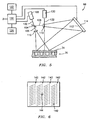
- FIG. 5 shows further details of the welding apparatus 68.
- the exemplary optical detection system of the apparatus 68 utilizes laser holography.
- a holographic laser generator 100 is positioned to direct an output beam 102 to a beam splitter 104 splitting the beam into first and second portions 106 and 108.
- the portion 108 serves as a reference passing through a lens 110 on its way to an incident surface 112 of a detector 114.
- the beam portion 106 passes through a lens 116 and is reflected from the surface 36 to the surface 112.
- the detector 114 may be connected to a control system 120 which may also be connected to the laser generator 100, to a display 122 and to a user input device 124 (e.g., a keyboard and pointing device).
- the control system 120 may also be connected to a welding beam generator 130 (e.g., a laser generator or an electron beam (e-beam) generator).
- the generator 130 directs a welding beam 132 to the surface 36.
- FIG. 6 shows an output of the display 122 with a fringe pattern 140 containing portions 142 indicating the presence of ribs.
- the display may further present an aiming indicia (e.g., cross-hairs 144) indicating an aim point of the beam 132.
- the control system may maintain alignment of the beam with a selected one of the ribs while traversing the beam along the rib to weld the two layers at the rib.
- the control system 120 may be coupled to the motor 62 and table 64 to control rotation and position of the precursor sandwich relative to an essentially stationary laser beam.
- the substrate could be stationary and the laser beam movable by means of an associated actuator (e.g., by moving just the beam 132 such as via rotating a mirror or by moving the welding beam generator alone or in combination with the holography beam 102, its generator, and/or its detector).
- an associated actuator e.g., by moving just the beam 132 such as via rotating a mirror or by moving the welding beam generator alone or in combination with the holography beam 102, its generator, and/or its detector.
- both may be movable.
- One example of the hybrid situation is where the precursor sandwich is only rotated about the axis 500 while the optical components of the system 68 are traversable in the direction 504.
- the system may accommodate irregularities (e.g., if nominally longitudinal channels and ribs fall slightly out of longitudinal). Also, the system may accommodate more complex rib and channel geometry.
Landscapes
- Engineering & Computer Science (AREA)
- Physics & Mathematics (AREA)
- Optics & Photonics (AREA)
- Mechanical Engineering (AREA)
- Plasma & Fusion (AREA)
- General Engineering & Computer Science (AREA)
- Chemical & Material Sciences (AREA)
- Combustion & Propulsion (AREA)
- Thermal Sciences (AREA)
- Laser Beam Processing (AREA)
- Welding Or Cutting Using Electron Beams (AREA)
- Lining Or Joining Of Plastics Or The Like (AREA)
- Length Measuring Devices By Optical Means (AREA)
Claims (21)
- Vorrichtung zum Schweißen einer ersten Platte (24) an eine zweite Platte (22) an verdeckten, separaten Kontaktstellen, wobei die erste Platte (24) eine Innenseite (34), die teilweise die zweite Platte (22) berührt, und eine gegenüberliegende Außenseite (36) hat, wobei die Vorrichtung Mittel (68; 130) zum Erzeugen eines Schweißstrahls (132) aufweist;
dadurch gekennzeichnet, dass die Vorrichtung weiter aufweist:Mittel (70) zum Reduzieren eines Drucks entlang der Innenseite (34) der ersten Platte (24) relativ zu einem benachbarten Druck entlang der Außenseite (36);
wobei diese Druckreduktion entlang eines ersten Bereichs (40) der ersten Platte (24), der die zweite Platte (22) nicht berührt, eine Biegung der ersten Platte (24) relativ zu einem zweiten Bereich (42) nach innen bewirkt; undMittel, um basierend auf dieser Biegung wenigstens einen des ersten Bereichs (40) oder des zweiten Bereichs (42) zu lokalisieren. - Vorrichtung nach Anspruch 1, weiter aufweisend Mittel, um den Schweißstrahl (132) in Reaktion auf das Lokalisieren auf den zweiten Bereich (42) zu richten.
- Vorrichtung nach Anspruch 1 der 2, wobei das Mittel zum Lokalisieren eine Laserholographievorrichtung aufweist.
- Vorrichtung nach Anspruch 1 oder 2, wobei das Mittel zum Lokalisieren eine Laserholographievorrichtung und eine Videoanzeige (122) aufweist, die Holographierandmuster von der Laserholographievorrichtung anzeigt.
- Vorrichtung nach einem der vorangehenden Ansprüche, wobei das Mittel (68; 130) zum Erzeugen des Schweißstrahls wenigstens ein Element eines Laserstrahl-Erzeugers und eines Elektronenstrahl-Erzeugers aufweist.
- Vorrichtung nach einem der vorangehenden Ansprüche, wobei das Mittel zum Reduzieren des Drucks ein Plenumelement (80) aufweist, das an die erste Platte (24) und an die zweite Platte (22) geschweißt ist.
- Vorrichtung nach Anspruch 1 weiter aufweisend:eine Befestigung (60), die bemessen ist, um in eine Anordnung (20) der ersten Platte (24) und der zweiten Platte (22) einzugreifen und diese zu halten;wobei das Mittel zum Erzeugen eines Schweißstrahls (132) einen Schweißstrahlgenerator (68; 138) aufweist, der angeordnet ist, um einen Schweißstrahl (132) auf die Anordnung (20) zu richten;
wobei das Mittel (70) zum Reduzieren eines Drucks eine Pumpe (70) aufweist, die mit der Befestigung (60) verbunden ist; und
wobei das Mittel zum Lokalisieren einen ersten Laserstrahl-Erzeuger (100), der angeordnet ist, um einen ersten Laserstrahl (102) auf die Außenseite (36) der ersten Platte (24) zu richten, und einen Detektor (114) aufweist, der angeordnet ist, um eine Reflexion des ersten Laserstrahls (102) zu erfassen. - Vorrichtung nach Anspruch 7, weiterhin aufweisend eine Steuerung (120), die mit dem Detektor (174) und dem Schweißstrahlgenerator (130) verbunden ist und die angeordnet ist, um den Schweißstrahl (132) in Reaktion auf das Erfassen der Reflexion auf den zweiten Bereich (42) zu richten.
- Vorrichtung nach Anspruch 7 oder 8, wobei der Schweißstrahtgenerator (130) einen zweiten Laserstrahl-Erzeuger aufweist.
- Vorrichtung nach Anspruch 7 oder 8, wobei der Schweißstrahlgenerator (130) einen Elektronenstrahl-Erzeuger aufweist.
- Vorrichtung nach einem der Ansprüche 7 bis 10, wobei der Schweißstrahlgenerator (130) einen Aktuator aufweist, um den Schweißstrahl (132) über die erste Platte zu verfahren.
- Vorrichtung nach einem der vorangehenden Ansprüche in Verbindung mit der ersten Platte (24) und der zweiten Platte (22), wobei,die erste Platte (24) ein im Wesentlichen flaches Blech ist; unddie zweite Platte (22) eine im Wesentlichen flache erste Seite (32) und eine zweite Seite hat, die eine Vielzahl von parallelen Rippen (30) hat.
- Verfahren des Schweißens einer ersten Platte (24) an eine zweite Platte (22), an verdeckten, separaten Kontaktstellen, wobei die erste Platte (24) eine Innenseite (34), die teilweise die zweite Platte (22) berührt, und eine gegenüberliegende Außenseite (36) hat, dadurch gekennzeichnet, dass das Verfahren beinhaltet:Reduzieren eines Drucks entlang der Innenseite (34) der ersten Platte (24) relativ zu einem benachbarten Druck entlang der Außenseite (36);
wobei das Reduzieren des Drucks das Biegen der ersten Platte (24) entlang eines ersten Bereiches (40) der ersten Platte (24), der nicht die zweite Platte (22) berührt, relativ zu einem zweiten Bereich (42) nach innen bewirkt;Lokalisieren, basierend auf dieser Biegung, wenigstens eines des ersten Bereichs (40) und des zweiten Bereichs (42); undRichten eines Schweißstrahls (132) auf den zweiten Bereich (42), in Reaktion auf das Lokalisieren. - Verfahren nach Anspruch 13, wobei das Lokalisieren Laserholographie beinhaltet.
- Verfahren nach Anspruch 13 oder 14, wobei das Richten bewirkt, dass der Schweißstrahl (132) die erste Platte entlang einer Vielzahl von parallelen Rippen (30) der zweiten Platte (22) an die zweite Platte (22) anschweißt.
- Verfahren nach Anspruch 13, 14 oder 15, weiterhin beinhaltend:Schweißen wenigstens eines Opfer-Dichtelements an die erste Platte (24) und an die zweite Platte (22).
- Verfahren nach Anspruch 16, wobei das Dichtelement ein kreisförmiges Plenumelement (80) ist.
- Verfahren nach einem der Ansprüche 13 bis 17, wobeidie erste und die zweite Platte im Wesentlichen einen Rotationskörper (20) um eine Längsachse (500) bilden; unddie erste und die zweite Platte fortschreitend stufenweise im Wesentlichen um die Längsachse (500) rotiert werden, um schrittweises Schweißen von einzelnen Stellen, die den zweiten Bereich (42) bilden, zu ermöglichen.
- Verfahren nach Anspruch 18, wobei den einzelnen Stellen Längsrippen (30) der zweiten Platte (22) zugeordnet sind und das Schweißen beinhaltet, die ersten und die zweite Platte (24, 22) relativ zu dem Schweißstrahl (132) im Wesentlichen in Längsrichtung zu verrücken.
- Verfahren nach Anspruch 19, wobei das Schweißen weiterhin dynamisches Korrigieren von Fehlern in der Rippenanordnung durch Rotieren der ersten und zweiten Platte (24, 22) im Wesentlichen um die Längsachse (500) beinhaltet.
- Verfahren nach einem der Ansprüche 13 bis 20, das weiterhin Fräsen einer Vielzahl von Kanälen (26) in die zweite Platte (22) beinhaltet, um Rippen (30) oder die Rippen (30) zu hinterlassen.
Applications Claiming Priority (1)
| Application Number | Priority Date | Filing Date | Title |
|---|---|---|---|
| US10/982,677 US6998570B1 (en) | 2004-11-04 | 2004-11-04 | Beam welding apparatus and methods |
Publications (2)
| Publication Number | Publication Date |
|---|---|
| EP1655097A1 EP1655097A1 (de) | 2006-05-10 |
| EP1655097B1 true EP1655097B1 (de) | 2008-07-02 |
Family
ID=35753390
Family Applications (1)
| Application Number | Title | Priority Date | Filing Date |
|---|---|---|---|
| EP05256847A Expired - Lifetime EP1655097B1 (de) | 2004-11-04 | 2005-11-04 | Schweissvorrichtung und -verfahren zum Verbinden eines ersten Bleches zu einem zweiten teilweise konktaktierenden Bleches unter Verwendung von mittels zum Druckverminderungen zwischen den beiden Blechen und mittels zum Lokalisieren erzeugte Dehnungen des ersten Bleches relativ zum zweiten Blech |
Country Status (7)
| Country | Link |
|---|---|
| US (1) | US6998570B1 (de) |
| EP (1) | EP1655097B1 (de) |
| JP (1) | JP2006130565A (de) |
| KR (1) | KR100719014B1 (de) |
| CN (1) | CN100537114C (de) |
| AT (1) | ATE399614T1 (de) |
| DE (1) | DE602005007833D1 (de) |
Cited By (1)
| Publication number | Priority date | Publication date | Assignee | Title |
|---|---|---|---|---|
| US11262142B2 (en) | 2016-04-26 | 2022-03-01 | Northrop Grumman Systems Corporation | Heat exchangers, weld configurations for heat exchangers and related systems and methods |
Families Citing this family (8)
| Publication number | Priority date | Publication date | Assignee | Title |
|---|---|---|---|---|
| EP2283919A1 (de) | 2009-08-13 | 2011-02-16 | Methanol Casale S.A. | Plattenwärmetauscher für isotherme chemische Reaktoren |
| DE102010007272B4 (de) * | 2010-02-08 | 2016-09-15 | Astrium Gmbh | Verfahren zur Herstellung einer regenerativ gekühlten Düsenerweiterung einer Raketenbrennkammer und Düsenerweiterung |
| NL2009446A (en) * | 2011-10-12 | 2013-04-15 | Asml Netherlands Bv | Radiation beam welding method, body and lithographic apparatus. |
| JP5950637B2 (ja) * | 2012-03-09 | 2016-07-13 | 三菱電機株式会社 | ビーム溶接治具およびビーム溶接方法 |
| US20130266818A1 (en) | 2012-04-10 | 2013-10-10 | Hamilton Sundstrand Corporation | Article including a weld joint |
| KR101644339B1 (ko) | 2014-10-24 | 2016-08-01 | 삼성중공업 주식회사 | 오버레이 용접장치 |
| DE102021103840A1 (de) | 2021-02-18 | 2022-08-18 | a.i.m. all in metal GmbH | Verfahren zum Verschweißen von zwei länglichen Materialbändern |
| CN114633011B (zh) * | 2022-05-05 | 2023-11-14 | 中国航发航空科技股份有限公司 | 一种电子束焊接盲焊的夹具装置及找正方法 |
Family Cites Families (10)
| Publication number | Priority date | Publication date | Assignee | Title |
|---|---|---|---|---|
| US2690653A (en) * | 1952-08-14 | 1954-10-05 | Dole Refrigerating Co | Stamped plate |
| GB1449044A (en) * | 1972-11-14 | 1976-09-08 | Kongsberg Vapenfab As | Procedures and apparatuses for determining the shapes of surfaces |
| JPH056360A (ja) * | 1991-06-27 | 1993-01-14 | Canon Inc | 文字処理装置 |
| DE4140729C2 (de) * | 1991-12-11 | 1995-11-16 | Balcke Duerr Ag | Verfahren und Vorrichtung zur Herstellung von Wärmetauscherelementen |
| US5713506A (en) * | 1995-12-14 | 1998-02-03 | General Electric Company | Vacuum holding rotary welding fixture |
| US5786533A (en) * | 1996-04-17 | 1998-07-28 | Michelin North America, Inc. | Method for analyzing a separation in a deformable structure |
| NL1004483C2 (nl) * | 1996-11-11 | 1998-05-14 | Omega Laser Systems B V | Lasinrichting. |
| SE512942C2 (sv) * | 1998-10-02 | 2000-06-12 | Volvo Aero Corp | Förfarande för tillverkning av utloppsmunstycken för raketmotorer |
| JP3818084B2 (ja) * | 2000-12-22 | 2006-09-06 | 日立電線株式会社 | 冷却板とその製造方法及びスパッタリングターゲットとその製造方法 |
| US7009136B2 (en) * | 2002-10-09 | 2006-03-07 | General Motors Corporation | Method of fabricating a bipolar plate assembly |
-
2004
- 2004-11-04 US US10/982,677 patent/US6998570B1/en not_active Expired - Fee Related
-
2005
- 2005-08-30 KR KR1020050079708A patent/KR100719014B1/ko not_active Expired - Fee Related
- 2005-11-02 JP JP2005319036A patent/JP2006130565A/ja not_active Ceased
- 2005-11-04 DE DE602005007833T patent/DE602005007833D1/de not_active Expired - Lifetime
- 2005-11-04 AT AT05256847T patent/ATE399614T1/de not_active IP Right Cessation
- 2005-11-04 EP EP05256847A patent/EP1655097B1/de not_active Expired - Lifetime
- 2005-11-04 CN CNB2005101188061A patent/CN100537114C/zh not_active Expired - Fee Related
Cited By (1)
| Publication number | Priority date | Publication date | Assignee | Title |
|---|---|---|---|---|
| US11262142B2 (en) | 2016-04-26 | 2022-03-01 | Northrop Grumman Systems Corporation | Heat exchangers, weld configurations for heat exchangers and related systems and methods |
Also Published As
| Publication number | Publication date |
|---|---|
| EP1655097A1 (de) | 2006-05-10 |
| US6998570B1 (en) | 2006-02-14 |
| CN1769001A (zh) | 2006-05-10 |
| KR100719014B1 (ko) | 2007-05-16 |
| ATE399614T1 (de) | 2008-07-15 |
| KR20060050776A (ko) | 2006-05-19 |
| CN100537114C (zh) | 2009-09-09 |
| JP2006130565A (ja) | 2006-05-25 |
| DE602005007833D1 (de) | 2008-08-14 |
Similar Documents
| Publication | Publication Date | Title |
|---|---|---|
| US20090314750A1 (en) | Gap control device and laser lap welding method | |
| US5498849A (en) | Structure of metal container having trunk pipe and branch pipe, and manufacturing method and apparatus therefor | |
| US6998570B1 (en) | Beam welding apparatus and methods | |
| CA2442961C (en) | Laser beam welding method and apparatus | |
| US9737960B2 (en) | Laser-based lap welding of sheet metal components using laser induced protuberances to control gap | |
| DE102009057209B4 (de) | Vorrichtung mit Scanner-Optik zur Materialbearbeitung mittels Laser | |
| US11331752B2 (en) | Backside surface welding system and method | |
| US6034347A (en) | Continuous butt-welding process and device for metal sheets, in particular for building car bodies in the car industry | |
| EP0814936A4 (de) | Verfahren zum überlappschweissen mittels eines höheren energiedichte aufweisenden strahlungsbündel | |
| CN104125872A (zh) | 对端面法兰连接进行缝焊的方法 | |
| JPS6032555B2 (ja) | レ−ザビ−ム溶接回転ヘツド | |
| US6060681A (en) | Process and apparatus for laser welding | |
| US20240082953A1 (en) | Method and laser processing apparatus for producing a bipolar plate | |
| JP7623476B2 (ja) | 板金部材の溶接のための方法 | |
| CN121131981A (zh) | 一种内腔曲面焊缝激光光路折转焊接方法 | |
| PT855235E (pt) | Processo de fabricacao de corpos de latas feitos de chapa | |
| JP2002301582A (ja) | レーザ溶接とtig溶接またはmig溶接との組合せによる厚板溶接方法 | |
| EP1118420A2 (de) | Überlappschweissen mittels eines geneigten Strahls | |
| JP5125001B2 (ja) | レーザ溶接方法、装置および設備 | |
| JPS5947083A (ja) | 高エネルギ−ビ−ムによる溶接方法 | |
| Goebel et al. | Laser welding with long focal length optics | |
| JPH10113783A (ja) | めっき鋼板のレーザ溶接方法 | |
| JPH0541355B2 (de) | ||
| EP3576900A1 (de) | Verfahren zur herstellung eines wärmetauschers für gase und durch besagtes verfahren hergestellter wärmetauscher für gase | |
| WO2021065067A1 (ja) | 溶接方法、板状部材およびエレベーター設備 |
Legal Events
| Date | Code | Title | Description |
|---|---|---|---|
| PUAI | Public reference made under article 153(3) epc to a published international application that has entered the european phase |
Free format text: ORIGINAL CODE: 0009012 |
|
| AK | Designated contracting states |
Kind code of ref document: A1 Designated state(s): AT BE BG CH CY CZ DE DK EE ES FI FR GB GR HU IE IS IT LI LT LU LV MC NL PL PT RO SE SI SK TR |
|
| AX | Request for extension of the european patent |
Extension state: AL BA HR MK YU |
|
| 17P | Request for examination filed |
Effective date: 20060504 |
|
| 17Q | First examination report despatched |
Effective date: 20060629 |
|
| AKX | Designation fees paid |
Designated state(s): AT BE BG CH CY CZ DE DK EE ES FI FR GB GR HU IE IS IT LI LT LU LV MC NL PL PT RO SE SI SK TR |
|
| GRAP | Despatch of communication of intention to grant a patent |
Free format text: ORIGINAL CODE: EPIDOSNIGR1 |
|
| RTI1 | Title (correction) |
Free format text: WELDING APPARATUS FOR AND METHOD OF WELDING A FIRST PANEL PARTIALLY CONTACTING A SECOND PANEL USING MEANS FOR REDUCING THE PRESSURE BETWEEN THE FIRST AND SECOND PANELS AND MEANS |
|
| GRAS | Grant fee paid |
Free format text: ORIGINAL CODE: EPIDOSNIGR3 |
|
| GRAA | (expected) grant |
Free format text: ORIGINAL CODE: 0009210 |
|
| AK | Designated contracting states |
Kind code of ref document: B1 Designated state(s): AT BE BG CH CY CZ DE DK EE ES FI FR GB GR HU IE IS IT LI LT LU LV MC NL PL PT RO SE SI SK TR |
|
| REG | Reference to a national code |
Ref country code: GB Ref legal event code: FG4D |
|
| REG | Reference to a national code |
Ref country code: CH Ref legal event code: EP |
|
| REF | Corresponds to: |
Ref document number: 602005007833 Country of ref document: DE Date of ref document: 20080814 Kind code of ref document: P |
|
| REG | Reference to a national code |
Ref country code: IE Ref legal event code: FG4D |
|
| PG25 | Lapsed in a contracting state [announced via postgrant information from national office to epo] |
Ref country code: SI Free format text: LAPSE BECAUSE OF FAILURE TO SUBMIT A TRANSLATION OF THE DESCRIPTION OR TO PAY THE FEE WITHIN THE PRESCRIBED TIME-LIMIT Effective date: 20080702 |
|
| PG25 | Lapsed in a contracting state [announced via postgrant information from national office to epo] |
Ref country code: NL Free format text: LAPSE BECAUSE OF FAILURE TO SUBMIT A TRANSLATION OF THE DESCRIPTION OR TO PAY THE FEE WITHIN THE PRESCRIBED TIME-LIMIT Effective date: 20080702 |
|
| NLV1 | Nl: lapsed or annulled due to failure to fulfill the requirements of art. 29p and 29m of the patents act | ||
| PG25 | Lapsed in a contracting state [announced via postgrant information from national office to epo] |
Ref country code: IS Free format text: LAPSE BECAUSE OF FAILURE TO SUBMIT A TRANSLATION OF THE DESCRIPTION OR TO PAY THE FEE WITHIN THE PRESCRIBED TIME-LIMIT Effective date: 20081102 Ref country code: LT Free format text: LAPSE BECAUSE OF FAILURE TO SUBMIT A TRANSLATION OF THE DESCRIPTION OR TO PAY THE FEE WITHIN THE PRESCRIBED TIME-LIMIT Effective date: 20080702 |
|
| PG25 | Lapsed in a contracting state [announced via postgrant information from national office to epo] |
Ref country code: LV Free format text: LAPSE BECAUSE OF FAILURE TO SUBMIT A TRANSLATION OF THE DESCRIPTION OR TO PAY THE FEE WITHIN THE PRESCRIBED TIME-LIMIT Effective date: 20080702 Ref country code: PT Free format text: LAPSE BECAUSE OF FAILURE TO SUBMIT A TRANSLATION OF THE DESCRIPTION OR TO PAY THE FEE WITHIN THE PRESCRIBED TIME-LIMIT Effective date: 20081202 Ref country code: AT Free format text: LAPSE BECAUSE OF FAILURE TO SUBMIT A TRANSLATION OF THE DESCRIPTION OR TO PAY THE FEE WITHIN THE PRESCRIBED TIME-LIMIT Effective date: 20080702 Ref country code: ES Free format text: LAPSE BECAUSE OF FAILURE TO SUBMIT A TRANSLATION OF THE DESCRIPTION OR TO PAY THE FEE WITHIN THE PRESCRIBED TIME-LIMIT Effective date: 20081013 Ref country code: BG Free format text: LAPSE BECAUSE OF FAILURE TO SUBMIT A TRANSLATION OF THE DESCRIPTION OR TO PAY THE FEE WITHIN THE PRESCRIBED TIME-LIMIT Effective date: 20081002 Ref country code: FI Free format text: LAPSE BECAUSE OF FAILURE TO SUBMIT A TRANSLATION OF THE DESCRIPTION OR TO PAY THE FEE WITHIN THE PRESCRIBED TIME-LIMIT Effective date: 20080702 |
|
| PG25 | Lapsed in a contracting state [announced via postgrant information from national office to epo] |
Ref country code: BE Free format text: LAPSE BECAUSE OF FAILURE TO SUBMIT A TRANSLATION OF THE DESCRIPTION OR TO PAY THE FEE WITHIN THE PRESCRIBED TIME-LIMIT Effective date: 20080702 |
|
| PG25 | Lapsed in a contracting state [announced via postgrant information from national office to epo] |
Ref country code: DK Free format text: LAPSE BECAUSE OF FAILURE TO SUBMIT A TRANSLATION OF THE DESCRIPTION OR TO PAY THE FEE WITHIN THE PRESCRIBED TIME-LIMIT Effective date: 20080702 Ref country code: EE Free format text: LAPSE BECAUSE OF FAILURE TO SUBMIT A TRANSLATION OF THE DESCRIPTION OR TO PAY THE FEE WITHIN THE PRESCRIBED TIME-LIMIT Effective date: 20080702 |
|
| PGFP | Annual fee paid to national office [announced via postgrant information from national office to epo] |
Ref country code: FR Payment date: 20081106 Year of fee payment: 4 |
|
| PLBE | No opposition filed within time limit |
Free format text: ORIGINAL CODE: 0009261 |
|
| STAA | Information on the status of an ep patent application or granted ep patent |
Free format text: STATUS: NO OPPOSITION FILED WITHIN TIME LIMIT |
|
| PG25 | Lapsed in a contracting state [announced via postgrant information from national office to epo] |
Ref country code: RO Free format text: LAPSE BECAUSE OF FAILURE TO SUBMIT A TRANSLATION OF THE DESCRIPTION OR TO PAY THE FEE WITHIN THE PRESCRIBED TIME-LIMIT Effective date: 20080702 Ref country code: CZ Free format text: LAPSE BECAUSE OF FAILURE TO SUBMIT A TRANSLATION OF THE DESCRIPTION OR TO PAY THE FEE WITHIN THE PRESCRIBED TIME-LIMIT Effective date: 20080702 Ref country code: SK Free format text: LAPSE BECAUSE OF FAILURE TO SUBMIT A TRANSLATION OF THE DESCRIPTION OR TO PAY THE FEE WITHIN THE PRESCRIBED TIME-LIMIT Effective date: 20080702 |
|
| 26N | No opposition filed |
Effective date: 20090403 |
|
| PG25 | Lapsed in a contracting state [announced via postgrant information from national office to epo] |
Ref country code: MC Free format text: LAPSE BECAUSE OF NON-PAYMENT OF DUE FEES Effective date: 20081130 |
|
| REG | Reference to a national code |
Ref country code: IE Ref legal event code: MM4A |
|
| PG25 | Lapsed in a contracting state [announced via postgrant information from national office to epo] |
Ref country code: IT Free format text: LAPSE BECAUSE OF FAILURE TO SUBMIT A TRANSLATION OF THE DESCRIPTION OR TO PAY THE FEE WITHIN THE PRESCRIBED TIME-LIMIT Effective date: 20080702 |
|
| PG25 | Lapsed in a contracting state [announced via postgrant information from national office to epo] |
Ref country code: IE Free format text: LAPSE BECAUSE OF NON-PAYMENT OF DUE FEES Effective date: 20081104 |
|
| PG25 | Lapsed in a contracting state [announced via postgrant information from national office to epo] |
Ref country code: SE Free format text: LAPSE BECAUSE OF FAILURE TO SUBMIT A TRANSLATION OF THE DESCRIPTION OR TO PAY THE FEE WITHIN THE PRESCRIBED TIME-LIMIT Effective date: 20081002 |
|
| PG25 | Lapsed in a contracting state [announced via postgrant information from national office to epo] |
Ref country code: PL Free format text: LAPSE BECAUSE OF FAILURE TO SUBMIT A TRANSLATION OF THE DESCRIPTION OR TO PAY THE FEE WITHIN THE PRESCRIBED TIME-LIMIT Effective date: 20080702 |
|
| REG | Reference to a national code |
Ref country code: CH Ref legal event code: PL |
|
| PG25 | Lapsed in a contracting state [announced via postgrant information from national office to epo] |
Ref country code: HU Free format text: LAPSE BECAUSE OF FAILURE TO SUBMIT A TRANSLATION OF THE DESCRIPTION OR TO PAY THE FEE WITHIN THE PRESCRIBED TIME-LIMIT Effective date: 20090103 Ref country code: CY Free format text: LAPSE BECAUSE OF FAILURE TO SUBMIT A TRANSLATION OF THE DESCRIPTION OR TO PAY THE FEE WITHIN THE PRESCRIBED TIME-LIMIT Effective date: 20080702 Ref country code: LU Free format text: LAPSE BECAUSE OF NON-PAYMENT OF DUE FEES Effective date: 20081104 |
|
| REG | Reference to a national code |
Ref country code: FR Ref legal event code: ST Effective date: 20100730 |
|
| PG25 | Lapsed in a contracting state [announced via postgrant information from national office to epo] |
Ref country code: TR Free format text: LAPSE BECAUSE OF FAILURE TO SUBMIT A TRANSLATION OF THE DESCRIPTION OR TO PAY THE FEE WITHIN THE PRESCRIBED TIME-LIMIT Effective date: 20080702 |
|
| PG25 | Lapsed in a contracting state [announced via postgrant information from national office to epo] |
Ref country code: LI Free format text: LAPSE BECAUSE OF NON-PAYMENT OF DUE FEES Effective date: 20091130 Ref country code: GR Free format text: LAPSE BECAUSE OF FAILURE TO SUBMIT A TRANSLATION OF THE DESCRIPTION OR TO PAY THE FEE WITHIN THE PRESCRIBED TIME-LIMIT Effective date: 20081003 Ref country code: FR Free format text: LAPSE BECAUSE OF NON-PAYMENT OF DUE FEES Effective date: 20091130 Ref country code: CH Free format text: LAPSE BECAUSE OF NON-PAYMENT OF DUE FEES Effective date: 20091130 |
|
| PGFP | Annual fee paid to national office [announced via postgrant information from national office to epo] |
Ref country code: DE Payment date: 20121031 Year of fee payment: 8 |
|
| PGFP | Annual fee paid to national office [announced via postgrant information from national office to epo] |
Ref country code: GB Payment date: 20121031 Year of fee payment: 8 |
|
| GBPC | Gb: european patent ceased through non-payment of renewal fee |
Effective date: 20131104 |
|
| REG | Reference to a national code |
Ref country code: DE Ref legal event code: R119 Ref document number: 602005007833 Country of ref document: DE Effective date: 20140603 |
|
| PG25 | Lapsed in a contracting state [announced via postgrant information from national office to epo] |
Ref country code: DE Free format text: LAPSE BECAUSE OF NON-PAYMENT OF DUE FEES Effective date: 20140603 |
|
| PG25 | Lapsed in a contracting state [announced via postgrant information from national office to epo] |
Ref country code: GB Free format text: LAPSE BECAUSE OF NON-PAYMENT OF DUE FEES Effective date: 20131104 |