EP1653634A2 - Anordnung und Verfahren zur Preamblesignalsendeleistungsregelung in einem OFDMA Kommunikationssystem - Google Patents
Anordnung und Verfahren zur Preamblesignalsendeleistungsregelung in einem OFDMA Kommunikationssystem Download PDFInfo
- Publication number
- EP1653634A2 EP1653634A2 EP20050023767 EP05023767A EP1653634A2 EP 1653634 A2 EP1653634 A2 EP 1653634A2 EP 20050023767 EP20050023767 EP 20050023767 EP 05023767 A EP05023767 A EP 05023767A EP 1653634 A2 EP1653634 A2 EP 1653634A2
- Authority
- EP
- European Patent Office
- Prior art keywords
- control mode
- power control
- transmit power
- transmitting
- data symbol
- Prior art date
- Legal status (The legal status is an assumption and is not a legal conclusion. Google has not performed a legal analysis and makes no representation as to the accuracy of the status listed.)
- Granted
Links
Images


Classifications
-
- H—ELECTRICITY
- H04—ELECTRIC COMMUNICATION TECHNIQUE
- H04W—WIRELESS COMMUNICATION NETWORKS
- H04W52/00—Power management, e.g. TPC [Transmission Power Control], power saving or power classes
- H04W52/04—TPC
- H04W52/38—TPC being performed in particular situations
- H04W52/42—TPC being performed in particular situations in systems with time, space, frequency or polarisation diversity
-
- H—ELECTRICITY
- H04—ELECTRIC COMMUNICATION TECHNIQUE
- H04W—WIRELESS COMMUNICATION NETWORKS
- H04W52/00—Power management, e.g. TPC [Transmission Power Control], power saving or power classes
- H04W52/04—TPC
- H04W52/06—TPC algorithms
- H04W52/08—Closed loop power control
-
- H—ELECTRICITY
- H04—ELECTRIC COMMUNICATION TECHNIQUE
- H04W—WIRELESS COMMUNICATION NETWORKS
- H04W52/00—Power management, e.g. TPC [Transmission Power Control], power saving or power classes
- H04W52/04—TPC
- H04W52/06—TPC algorithms
- H04W52/10—Open loop power control
-
- H—ELECTRICITY
- H04—ELECTRIC COMMUNICATION TECHNIQUE
- H04W—WIRELESS COMMUNICATION NETWORKS
- H04W52/00—Power management, e.g. TPC [Transmission Power Control], power saving or power classes
- H04W52/04—TPC
- H04W52/06—TPC algorithms
- H04W52/12—Outer and inner loops
-
- H—ELECTRICITY
- H04—ELECTRIC COMMUNICATION TECHNIQUE
- H04W—WIRELESS COMMUNICATION NETWORKS
- H04W52/00—Power management, e.g. TPC [Transmission Power Control], power saving or power classes
- H04W52/04—TPC
- H04W52/06—TPC algorithms
- H04W52/14—Separate analysis of uplink or downlink
- H04W52/146—Uplink power control
-
- H—ELECTRICITY
- H04—ELECTRIC COMMUNICATION TECHNIQUE
- H04W—WIRELESS COMMUNICATION NETWORKS
- H04W52/00—Power management, e.g. TPC [Transmission Power Control], power saving or power classes
- H04W52/04—TPC
- H04W52/06—TPC algorithms
- H04W52/16—Deriving transmission power values from another channel
-
- H—ELECTRICITY
- H04—ELECTRIC COMMUNICATION TECHNIQUE
- H04W—WIRELESS COMMUNICATION NETWORKS
- H04W52/00—Power management, e.g. TPC [Transmission Power Control], power saving or power classes
- H04W52/04—TPC
- H04W52/18—TPC being performed according to specific parameters
- H04W52/26—TPC being performed according to specific parameters using transmission rate or quality of service QoS [Quality of Service]
- H04W52/262—TPC being performed according to specific parameters using transmission rate or quality of service QoS [Quality of Service] taking into account adaptive modulation and coding [AMC] scheme
-
- H—ELECTRICITY
- H04—ELECTRIC COMMUNICATION TECHNIQUE
- H04W—WIRELESS COMMUNICATION NETWORKS
- H04W52/00—Power management, e.g. TPC [Transmission Power Control], power saving or power classes
- H04W52/04—TPC
- H04W52/18—TPC being performed according to specific parameters
- H04W52/28—TPC being performed according to specific parameters using user profile, e.g. mobile speed, priority or network state, e.g. standby, idle or non transmission
- H04W52/285—TPC being performed according to specific parameters using user profile, e.g. mobile speed, priority or network state, e.g. standby, idle or non transmission taking into account the mobility of the user
-
- H—ELECTRICITY
- H04—ELECTRIC COMMUNICATION TECHNIQUE
- H04W—WIRELESS COMMUNICATION NETWORKS
- H04W52/00—Power management, e.g. TPC [Transmission Power Control], power saving or power classes
- H04W52/04—TPC
- H04W52/18—TPC being performed according to specific parameters
- H04W52/28—TPC being performed according to specific parameters using user profile, e.g. mobile speed, priority or network state, e.g. standby, idle or non transmission
- H04W52/286—TPC being performed according to specific parameters using user profile, e.g. mobile speed, priority or network state, e.g. standby, idle or non transmission during data packet transmission, e.g. high speed packet access [HSPA]
Definitions
- the present invention relates to a communication system using an Orthogonal Frequency Division Multiple Access (OFDMA) scheme, and more particularly to an apparatus and a method for controlling transmit power of a preamble sequence for an Adaptive Antenna System (AAS).
- OFDMA Orthogonal Frequency Division Multiple Access
- a 4 th generation (4G) communication system which is the next generation communication system
- QoSs Qualities of Services
- a 4G communication system research is being performed to provide users with services having various Qualities of Services (QoSs) at a high transmission speed.
- QoSs Qualities of Services
- a Broadband Wireless Access (BWA) communication system such as a wireless Local Area Network (LAN) system and a wireless Metropolitan Area Network (MAN) system.
- BWA Broadband Wireless Access
- LAN wireless Local Area Network
- MAN wireless Metropolitan Area Network
- Representative communication systems of the 4G communication system are the Institute of Electrical and Electronics Engineers (IEEE) 802.16d communication system and the IEEE 802.16e communication system.
- the IEEE 802.16d communication system and the IEEE 802.16e communication system utilize an Orthogonal Frequency Division Multiplexing (OFDM) scheme/an OFDMA scheme to support a broadband transmission network for a physical channel of the wireless MAN system.
- OFDM Orthogonal Frequency Division Multiplexing
- the IEEE 802.16d communication system considers only a single cell structure and stationary subscriber stations (SSs), which means the system does not accommodate the mobility of the SSs at all.
- SSs stationary subscriber stations
- the IEEE 802.16e communication system accommodates the mobility of an SS in the IEEE 802.16d communication system.
- the IEEE 802.16e communication system expands a cell service area by means of a multi-antenna, and uses a Space Division Multiple Access (SDMA) scheme for increasing the total capacity.
- SDMA Space Division Multiple Access
- CQI Channel Quality Information
- BS Base Station
- FIG. 1 is a diagram schematically illustrating the general structure of an IEEE 802.16e communication system using an SDMA scheme.
- a BS 101 allocates the same time and frequency resources so that different SSs can simultaneously use the time and frequency resources in both a first space channel transmitted through a first beam 102 and a second space channel transmitted through a second beam 103.
- the BS 101 In order to allocate the same time and frequency resources to the different SSs, the BS 101 generates a plurality of spatially separated beams.
- the general IEEE 802.16e communication system transmits an AAS preamble sequence to a downlink and an uplink in order to support an AAS, thereby having knowledge of the exact downlink and uplink channel states.
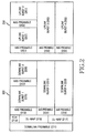
- FIG. 2 is a diagram schematically illustrating the general frame structure of an IEEE 802.16e communication system.
- the frame is classified into a downlink frame 200 and an uplink frame 250.
- the downlink frame 200 includes a downlink preamble field 211, a Frame Control Header (FCH) field 213, a downlink MAP (DL-MAP) field 215, an uplink MAP (UL-MAP) field 217, a plurality of AAS preamble fields 219, 221, 223 and 227, and a plurality of downlink burst fields, i.e., a first downlink burst field 225, a second downlink burst field 229, a third downlink burst field 231 and a fourth downlink burst field 233.
- FCH Frame Control Header
- DL-MAP downlink MAP
- UL-MAP uplink MAP
- a plurality of downlink burst fields i.e., a first downlink burst field 225, a second downlink burst field 229, a third downlink burst field 231 and a fourth down
- the downlink preamble field 211 is a field to which synchronization signals (i.e., a downlink preamble sequence) are transmitted in order to acquire synchronization (i.e., transmission/reception interval) between a BS and an SS.
- the FCH field 213 is a field through which basic information for a sub-channel, such as a ranging, a modulation scheme, etc., is transmitted.
- the DL-MAP field 215 is a field through which a DL-MAP message is transmitted
- the UL-MAP field 217 is a field through which a UL-MAP message is transmitted.
- the AAS preamble fields 219, 221, 223 and 227 are fields through which downlink AAS preamble sequences for AAA support are transmitted, and the downlink burst fields 225, 229, 231 and 233 are fields through which downlink data targeting SSs are transmitted.
- the uplink frame 250 includes a plurality of AAS preamble fields 251, 253, 255 and 259, and a plurality of uplink burst fields, i.e., a first uplink burst field 257, a second uplink burst field 261, a third uplink burst field 263 and a fourth uplink burst field 265.
- the AAS preamble fields 251, 253, 255 and 259 are fields through which uplink AAS preamble sequences for AAA support are transmitted
- the uplink burst fields 257, 261, 263 and 265 are fields through which uplink data targeting a BS are transmitted from the SSs.
- the BS estimates uplink channel states through the uplink AAS preamble sequences, and generates a downlink beam according to the estimated uplink channel states.
- the AAS preamble sequences have been defined as different sequences in each space channel, i.e., each beam.
- the IEEE 802.16e communication system has not proposed a scheme for controlling transmit power used for transmitting the AAS preamble sequence, it is impossible to understand a transmit power relation between the AAS preamble sequence and a data burst. Therefore, normal uplink data decoding is impossible. Accordingly, for the IEEE 802.16e communication system, it is necessary to provide a scheme for controlling transmit power used for transmitting the AAS preamble sequence.
- the present invention has been designed to solve the above-mentioned problems occurring in the prior art, and it is an object of the present invention to provide an apparatus and a method for controlling transmit power of an AAS preamble sequence in an OFDMA communication system.
- a method for controlling transmit power of a preamble sequence by a Subscriber Station (SS) in an Orthogonal Frequency Division Multiple Access (OFDMA) communication system the OFDMA communication system dividing an entire frequency band into a plurality of sub-carrier bands; transmitting a preamble sequence for an Adaptive Antenna System (AAS) through a predetermined number of sub-carrier bands from among the sub-carrier bands; and transmitting a data symbol through remaining sub-carrier bands excluding the sub-carrier bands used for transmitting the preamble sequence.
- the method includes determining the transmit power used for transmitting the data symbol; and determining the transmit power used for transmitting the preamble sequence to be identical to the transmit power of the data symbol.
- a method for controlling transmit power of a preamble sequence by a Subscriber Station (SS) in an Orthogonal Frequency Division Multiple Access (OFDMA) communication system the OFDMA communication system dividing an entire frequency band into a plurality of sub-carrier bands; transmitting a preamble sequence for an Adaptive Antenna System (AAS) through a predetermined number of sub-carrier bands from among the sub-carrier bands; and transmitting a data symbol through remaining sub-carrier bands excluding the sub-carrier bands used for transmitting the preamble sequence.
- the method includes determining the transmit power used for transmitting the preamble sequence to be identical to a preset threshold transmit power.
- a method for controlling transmit power of a preamble sequence by a Subscriber Station (SS) in an Orthogonal Frequency Division Multiple Access (OFDMA) communication system the OFDMA communication system dividing an entire frequency band into a plurality of sub-carrier bands; transmitting a preamble sequence for an Adaptive Antenna System (AAS) through a predetermined number of sub-carrier bands from among the sub-carrier bands; and transmitting a data symbol through remaining sub-carrier bands excluding the sub-carrier bands used for transmitting the preamble sequence.
- AAS Adaptive Antenna System
- the method including determining the transmit power used for transmitting the data symbol; and determining the transmit power used for transmitting the preamble sequence to be identical to a preset threshold transmit power when the transmit power of the data symbol is smaller than the threshold transmit power, and determining the transmit power used for transmitting the preamble sequence to be identical to the transmit power of the data symbol when the transmit power of the data symbol exceeds the threshold transmit power.
- an apparatus for controlling transmit power of a preamble sequence by a Subscriber Station (SS) in an Orthogonal Frequency Division Multiple Access (OFDMA) communication system the OFDMA communication system dividing an entire frequency band into a plurality of sub-carrier bands, transmitting a preamble sequence for an Adaptive Antenna System (AAS) through a predetermined number of sub-carrier bands from among the sub-carrier bands, transmitting a data symbol through the remaining sub-carrier bands excluding the sub-carrier bands used for transmitting the preamble sequence.
- AAS Adaptive Antenna System
- the apparatus includes a transmit power controller for determining transmit power used for transmitting the data symbol, and determining the transmit power used for transmitting the preamble sequence to be identicalto the transmit power of the data symbol; and a mobility estimator for detecting a mobility index of the SS.
- an apparatus for controlling transmit power of a preamble sequence by a Subscriber Station (SS) in an Orthogonal Frequency Division Multiple Access (OFDMA) communication system, the OFDMA communication system dividing an entire frequency band into a plurality of sub-carrier bands, transmitting a preamble sequence for an Adaptive Antenna System (AAS) through a predetermined number of sub-carrier bands from among the sub-carrier bands, transmitting a data symbol through the remaining sub-carrier bands excluding the sub-carrier bands used for transmitting the preamble sequence.
- the apparatus includes a transmit power controller for determining the transmit power used for transmitting the preamble sequence to be identical to a preset threshold transmit power.
- an apparatus for controlling transmit power of a preamble sequence by a Subscriber Station (SS) in an Orthogonal Frequency Division Multiple Access (OFDMA) communication system the OFDMA communication system dividing an entire frequency band into a plurality of sub-carrier bands, transmitting a preamble sequence for an Adaptive Antenna System (AAS) through a predetermined number of sub-carrier bands from among the sub-carrier bands, transmitting a data symbol through the remaining sub-carrier bands excluding the sub-carrier bands used for transmitting the preamble sequence.
- AAS Adaptive Antenna System
- the apparatus includes a transmit power controller for determining the transmit power used for transmitting the data symbol, determining the transmit power used for transmitting the preamble sequence to be identical to a preset threshold transmit power when the transmit power of the data symbol is smaller than the threshold transmit power, and determining the transmit power used for transmitting the preamble sequence to be identical to the transmit power of the data symbol when the transmit power of the data symbol exceeds the threshold transmit power; and a mobility estimator for detecting a mobility index of the SS.
- the present invention provides an apparatus and a method for controlling transmit power of a preamble sequence for an Adaptive Antenna System (AAS) in a communication system, which uses an Orthogonal Frequency Division Multiple Access (OFDMA) scheme, e.g., an Institute of Electrical and Electronics Engineers (IEEE) 802.16e communication system.
- OFDMA Orthogonal Frequency Division Multiple Access
- IEEE 802.16e an Institute of Electrical and Electronics Engineers 802.16e communication system.
- the present invention proposes an apparatus and a method for controlling transmit power of an AAS preamble sequence, which maximizes the efficiency of transmit power resources by controlling the transmit power of the AAS preamble sequence in consideration of a relation with transmit power of a data burst, i.e., a data symbol.
- an IEEE 802.16e communication system is described as one example for convenience of description. However, it is apparent to those skilled in the art that other communication systems using the OFDMA scheme may use an apparatus and a method for controlling transmit power of an
- each of the downlink bursts and each of the uplink bursts in the IEEE 802.16e communication system include a plurality of sub-carriers, respectively.
- AAS preamble sequences are respectively inserted before the downlink bursts for transmission.
- the same AAS preamble sequences are respectively inserted before the uplink bursts for transmission.
- Each of the inserted AAS preamble sequences has an Orthogonal Frequency Division Multiplexing (OFDM) symbol length defined in the same sub-carriers.
- OFDM Orthogonal Frequency Division Multiplexing
- the AAS preamble sequences have been defined as different sequences in each space channel, i.e., each beam.
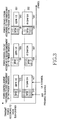
- AAS preamble sequence transmit power control schemes according to first to third embodiments of the present invention will be described with reference to FIG. 3.
- FIG. 3 is a diagram schematically illustrating the AAS preamble sequence transmit power control schemes according to the first to the third embodiments of the present invention when a Base Station (BS) transmits data to two Subscriber Stations (SSs), i.e., an SS 1 and an SS 2, in an IEEE 802.16e communication system.
- BS Base Station
- SSs Subscriber Stations
- the AAS preamble sequence is set to have the same transmit power as that of a data symbol.
- the transmit power of the AAS preamble sequence is set to be always identical to a preset transmit power, i.e., threshold transmit power. That is, in the AAS preamble sequence transmit power control scheme according to the second embodiment of the present invention, the transmit power of the AAS preamble sequence is set independent of transmit power of a data symbol.
- the threshold transmit power is determined according to a preset Carrier-to-Interference and Noise Ratio (CINR), i.e., a CINR req which is a reception request CINR.
- CINR Carrier-to-Interference and Noise Ratio
- Table 1 MCS level CINR req (dB) Fast Feedback 0 CDMA Code 3 AAS Preamble 6 Sounding Transmission 9 QPSK 1/2 6 QPSK 3/4 9 16 QAM 1/2 12 16 QAM 3/4 15
- the Modulation and Coding Scheme (MCS) level is generated according to use of an Adaptive Modulation and Coding (AMC) scheme by the OFDMA communication system. Because the generation of the MCS level has no direct connection to the present invention, a detailed description will be omitted.
- the reference CINR defined on an uplink in the OFDMA communication system has a value of 0 dB in case of the fast feedback, 3 dB in case of the Code Division Multiple Access (CDMA) code, 6 dB in case of the AAS preamble sequence, and 9 dB in case of the sounding transmission.
- CDMA Code Division Multiple Access
- the reference CINR has a value of 6 dB when a modulation scheme is the Quadrature Phase Shift Keying (QPSK) scheme and the coding rate is 1/2, 9 dB when the modulation scheme is the QPSK scheme and the coding rate is 3/4, 12 dB when the modulation scheme is the 16 Quadrature Amplitude Modulation (QAM) scheme and the coding rate is 1/2, and 15 dB when the modulation scheme is the 16 QAM scheme and the coding rate is 3/4.
- the sounding transmission represents that SSs having not received uplink frames transmit sounding symbols in the IEEE 802.16e communication system.
- the threshold transmit power of the AAS preamble sequence is determined according to the CINR of 6 dB.
- the transmit power of the other data symbols are determined according to the reference CINRs as illustrated in Table 1.
- the transmit power of the AAS preamble sequence is set to be identical to preset transmit power, i.e., threshold transmit power. Then, when the transmit power of a data symbol is smaller than the threshold transmit power, the AAS preamble sequence is set to be identical to the threshold transmit power. However, when the transmit power of the data symbol exceeds the threshold transmit power, the AAS preamble sequence is set to have the same transmit power as that of the data symbol.
- the AAS preamble sequence transmit power control scheme according to the third embodiment of the present invention is a combination of the AAS preamble sequence transmit power control scheme according to the first embodiment of the present invention and the AAS preamble sequence transmit power control scheme according to the second embodiment of the present invention.
- the threshold transmit power is determined according to the reference CINRs having been preset in the IEEE 802.16e communication system as illustrated in Table 1.
- the AAS preamble sequence is set to have the same transmit power as that of the data symbol as described above.
- the SS 1 sets the AAS preamble sequence 311 modulated by a Binary Phase Shift Keying (BPSK) scheme to have the same transmit power as that of the data symbol 313 modulated by the QPSK scheme and coded at the coding rate of 1/2.
- the SS 2 sets the AAS preamble sequence 315 modulated by the BPSK scheme to have the same transmit power as that of the data symbol 317 modulated by the 16 QAM scheme and coded at the coding rate of 3/4.
- BPSK Binary Phase Shift Keying
- the transmit power of the AAS preamble sequence is set to be always identical to the preset transmit power, i.e., the threshold transmit power, regardless of the transmit power of the data symbol.
- the SS 1 sets the AAS preamble sequence 331 modulated by the BPSK scheme to have transmit power identical to the threshold transmit power
- the SS 2 sets the AAS preamble sequence 335 modulated by the BPSK scheme to have transmit power identical to the threshold transmit power, i.e., the transmit power of the AAS preamble sequence 331.
- the transmit power of the AAS preamble sequence when the transmit power of the data symbol is smaller than the threshold transmit power, the transmit power of the AAS preamble sequence is set to be identical to the threshold transmit power. However, when the transmit power of the data symbol exceeds the threshold transmit power, the AAS preamble sequence is set to have the same transmit power as that of the data symbol.
- the SS 1 sets the AAS preamble sequence 351 modulated by the BPSK scheme to have transmit power identical to the threshold transmit power
- the SS 2 sets the AAS preamble sequence 355 modulated by the BPSK scheme to have the same transmit power as that of the AAS preamble sequence 357 modulated by the 16 QAM scheme and coded at the coding rate of 3/4.
- the corresponding transmit power set as the transmit power of the AAS preamble sequence changes when an open loop power control mode is employed, and when a closed loop power control mode and an outer loop power control mode are employed. This will be described with reference to Table 2 below.
- Table 2 AAS preamble sequence Data symbol SS determination BS determination SS determination BS determination First embodiment Open loop O X O X Closed loop X O X O Second embodiment Open loop O X O X Closed loop X O X O Outer loop O X X O
- Table 2 shows a BS and an SS for controlling (i.e., determining) the transmit power of the AAS preamble sequence and the data symbol when the open loop power control mode, the closed loop power control mode, and the outer loop power control mode are used for the AAS preamble sequence transmit power control schemes according to the first and the second embodiments of the present invention.
- the open loop power control mode represents a mode in which an SS controls its own transmit power by estimating path loss.
- the closed loop power control mode represents a mode in which a BS controls transmit power of SSs by estimating CINRs of the SSs.
- the outer loop power control mode represents a mode for finely adjusting transmit power by reflecting a reception error probability of actually received data symbols.
- the outer loop power control mode may be used together with the open loop power control mode or the closed loop power control mode.
- an SS determines the transmit power of an uplink data symbol.
- the SS uses both an estimated value for uplink propagation path loss and BS reception interference and noise reported by a BS. This may be expressed by Equation (1) below.
- P ( dB m ) L + CINR req + NI ⁇ 10 ⁇ log 10 ( R ) + Offset perSS
- Equation (1) P(dB m ) represents the transmit power of the uplink data symbol according to each sub-carrier, and L represents the estimated value for the uplink propagation path loss and includes a transmit/receive antenna gain.
- CINR req represents a CINR (i.e., a reference CINR) required for an MCS level of the uplink data symbol, and this has been stipulated in advance between the SS and the BS as described in Table 1. Specifically, both a reference CINR of uplink acknowledge (UL ACK) signals and a reference CINR when a modulation scheme is the QPSK scheme and a coding rate is 1/3 are transmitted to the SS from the BS through a Uplink Channel Descript (UCD) message.
- NI represents an estimated value for interference and noise according to each sub-carrier in a receiver of the BS, and is transferred to the SS from the BS through an uplink noise and interference level Information Element (UL Noise and Interference Level IE).
- R represents a repetition factor when a repetition code is used. R is considered only when the transmit power of the data symbol is computed, but it is not considered for the transmit power of the AAS preamble sequence.
- the data symbol when the data symbol must be modulated by a QPSK modulation scheme and coded at a coding rate of 1/4, the data symbol may be generated through the use of the QPSK modulation scheme and repetition of a coding rate of 1/2 as illustrated in Table 1. In this case, transmit power according to each sub-carrier is reduced to 1/2.
- the operation point of the AAS preamble sequence i.e., the threshold transmit power of the AAS preamble sequence, as described in Table 1 is determined in inverse proportion to symbol intervals transmitting the AAS preamble sequence.
- Offset perSS represents a power compensation value according to each SS. Offset perSS is transmitted from a BS to the SSs through a Power control Mode Change (PMC)_ReSPonse (RSP) Medium Access Control (MAC) message. Further, Offset perSS is a value computed reflecting the reception error probability of received data. When Offset perSS is reflected, it is possible to obtain an effect for the use of the outer loop power control mode as well as the open loop power control mode.
- PMC Power control Mode Change
- RSP Medium Access Control
- MAC Medium Access Control
- the SS may change Offset perSS as expressed by Equation (2) below.
- Offset perSS Offset perSS + UP_STEP if NACK is received
- Offset perSS Offset perSS ⁇ 1 1 / FER target ⁇ UP_STEP else if ACK is received
- Offset perSS Offset perSS elsewhere Offset_Bound lower ⁇ Offset perSS ⁇ Offset_Bound upper
- UP_STEP represents an offset increment when an NACK is received;
- FER target represents a target Frame Error Rate (FER);
- Offset_Bound lower represents a lower bound value permitted to Offset perSS ;
- Offset_Bound upper represents an upper bound value permitted to Offset perSS. All of the UP_STEP, the FER t arg et , the Offset_ Bound lower , and the Offset_Bound upper are transmitted from a BS to SSs through the UCD message, etc.
- a BS controls the transmit power of an SS.
- the BS estimates a CINR whenever receiving an uplink burst such as a ranging code, a CQI, ACK signals and uplink data.
- the BS changes the estimated CINR into a CINR for the ranging code, and computes the difference between the changed CINR and a reference CINR for the ranging code. This difference may be expressed by Equation (3) below.
- Equation (3) CINR CDMA_req ⁇ ( CINR UL ⁇ RangingDataRatio )
- ⁇ P represents the difference between the CINR of the ranging code changed using the estimated CINR of the uplink burst and the reference CINR for the ranging code.
- CINR CDMA_req represents a reference CINR value required when an initial ranging and a periodic ranging are performed, and has been stipulated between the BS and SSs.
- CINR UL represents a CINR of combined signals when a repetition code is used as a CINR of a received uplink burst.
- RangingDataRatio represents the difference between a CINR required by an uplink burst to be currently transmitted and a CINR required by a CDMA ranging.
- CINR UL and RangingDataRatio are transmitted from the BS to the SSs through an UCD burst profile.
- the BS selectively transmits ⁇ P and ⁇ P i to the SSs through a transmit power control command according to the type of an uplink burst used for estimation of ⁇ P.
- ⁇ P i represents an i th power compensation value.
- the SS determines the transmit power according to each sub-carrier of an uplink data symbol in response to the transmit power control command received from the BS. This may be expressed by Equation (4) below.
- P ( dB m ) P CDMA + RangingDataRatio ⁇ 10 log 10 ( R ) + ⁇ i ⁇ ( last CDMA ranging ) ⁇ P i
- Equation (4) P(dB m ) represents the transmit power according to each sub-carrier of the uplink data symbol, and P CDMA represents the transmit power according to each sub-carrier of a CDMA code determined when an initial ranging and a periodic ranging is performed.
- R is a value identical to the R in Equation (1), which represents a repetition ratio applied to the current uplink data symbol.
- ⁇ i ⁇ ( last CDMA ranging ) ⁇ P i represents the total sum of the TPC commands received in an SS after P CDMA is determined in the most recent time period.
- the AAS preamble sequence transmit power control scheme according to the first embodiment of the present invention is utilized as illustrated in Table 2, when the open loop power control mode is used, an SS determines AAS preamble sequence transmit power and data symbol transmit power. However, when the closed loop power control mode is used, a BS determines the AAS preamble sequence transmit power and the data symbol transmit power.
- an SS determines the AAS preamble sequence transmit power and the data symbol transmit power.
- a BS determines the AAS preamble sequence transmit power and the data symbol transmit power.
- the SS determines the AAS preamble sequence transmit power and the BS determines the data symbol transmit power.
- the AAS preamble sequence transmit power control scheme according to the third embodiment of the present invention when the data symbol transmit power is smaller than the preset transmit power (i.e., the threshold transmit power) as described above, the AAS preamble sequence transmit power is controlled in the same manner as the AAS preamble sequence transmit power control scheme according to the second embodiment of the present invention. However, when the data symbol transmit power exceeds the threshold transmit power, the AAS preamble sequence transmit power is controlled in the same manner as the AAS preamble sequence transmit power control scheme according to the first embodiment of the present invention.
- the preset transmit power i.e., the threshold transmit power
- the AAS preamble sequence transmit power control scheme according to the third embodiment of the present invention when the scheme is performed in the same manner as the AAS preamble sequence transmit power control scheme according to the second embodiment of the present invention, the same operation is performed in the same manner as the AAS preamble sequence transmit power control scheme according to the second embodiment of the present invention as illustrated in Table 2. Further, when the scheme is performed in the same manner as the AAS preamble sequence transmit power control scheme according to the first embodiment of the present invention, the same operation is performed in the same manner as the AAS preamble sequence transmit power control scheme according to the first embodiment of the present invention as illustrated in Table 2. Accordingly, a detailed description will be omitted.
- the AAS preamble sequence transmit power control scheme is used in the open loop power control mode or the closed loop power control mode is set in the same manner as in the data symbol transmit power control scheme.
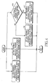
- FIG. 4 is a flow diagram illustrating processes for controlling the transmit power of the AAS preamble sequence according to the first to the third embodiments of the present invention.
- the SS when an SS uses the AAS preamble sequence transmit power control scheme according to the first embodiment of the present invention, the SS sets an AAS preamble sequence to have the same transmit power as that of a data symbol in step 411 and the control process ends.
- the SS uses the AAS preamble sequence transmit power control scheme according to the second embodiment of the present invention, the SS sets the AAS preamble sequence to have transmit power identical to the preset threshold transmit power in step 413 and the control process ends.
- the SS determines if the transmit power of the data symbol exceeds the threshold transmit power in step 415. As a result of the determination, when the transmit power of the data symbol exceeds the threshold transmit power, step 417 is performed. In step 417, the SS sets the AAS preamble sequence to have the same transmit power as that of the data symbol, and the control process ends. However, when the transmit power of the data symbol is smaller than the threshold transmit power, step 419 is performed. In step 419, the SS sets the AAS preamble sequence to have transmit power identical to the threshold transmit power, and the control process ends.
- the transmit power of the AAS preamble sequence and the transmit power of the data symbol are respectively computed according to the power control mode being used, i.e., the open loop power control mode, the closed loop power control mode, or the outer loop power control mode.
- FIG. 5 is a flow diagram illustrating a process by which an SS requests a change of a transmit power control mode while performing the processes for controlling the transmit power of the AAS preamble sequence according to the first to the third embodiments of the present invention.
- the SS determines if the mobility index of the SS is less than a preset threshold mobility index in step 511.
- the mobility index is a value representing the mobility of the SS, which may be computed by measuring the reception CINR of reference signals such as downlink preamble sequences or uplink pilot signals and considering time change of the measured CINR.
- the closed loop power control mode having superior performance is used.
- the open loop power control mode is used.
- step 513 is performed.
- Setting the variable PMC' to have a value of 0 represents that the power control mode is to be set as the closed loop power control mode.
- step 517 the SS determines if a variable PMC representing the currently set power control mode has a value different from that of the variable PMC' representing the power control mode to be set later. As a result of determination in step 517, when the variable PMC does not have a value different from that of the variable PMC', the SS maintains the current power control mode, and the process ends. However, when the variable PMC has a value different from that of the variable PMC', step 519 is performed. In step 519, the SS transmits a power control mode change request to a BS because the current power control mode is different from the power control mode to be set later. Then, the process ends.
- FIG. 6 is a flow diagram illustrating a process for changing a transmit power control mode while performing the processes for controlling the transmit power of the AAS preamble sequence according to the first to the third embodiments of the present invention.
- the SS transmits the power control mode change request to the BS (step 611).
- the BS transmits a power control mode change command to the SS in response to the power control mode change request (step 613).
- FIG. 6 a case in which the SS transmits the power control mode change request to the BS is described as one example. However, it is apparent to those skilled in the art that the BS can transmit the power control mode change command to the SS even without the power control mode change request from the SS.
- FIG. 7 is a block diagram illustrating the construction of the BS for performing functions in the embodiments of the present invention.
- the BS includes an MAC entity 711, a Time Division Duplex (TDD) transmission modem 713, a transmit antenna Tx ANT 715, a receive antenna Rx ANT 717, a TDD reception modem 719, a mobility estimator 721, a transmit power controller 723, and a scheduler 725.
- TDD Time Division Duplex
- the MAC entity 711 performs an interface with an upper layer, and outputs a DL-MAP message, an UL-MAP message, etc., which include scheduling information according to scheduling of the scheduler 725, to the TDD transmission modem 713.
- the DL-MAP message and the UL-MAP message are provided from the scheduler 725.
- the TDD transmission modem 713 modulates the DL-MAP message, the UL-MAP message, etc., which are output from the MAC entity 711, by an OFDMA scheme; performs an RF processing for the modulated messages; and transmits the processed messages to SSs through the transmit antenna 715.
- the TDD reception modem 719 down-converts the signals received through the receive antenna 717 into baseband signals, demodulates the baseband signals correspondingly to the OFDMA scheme, and outputs the demodulated baseband signals to the mobility estimator 721.
- the mobility estimator 721 receives the signals output from the TDD reception modem 719, estimates the mobilities of the SSs, and outputs the mobility indices to the transmit power controller 723.
- the transmit power controller 723 generates a power control mode change command with reference to the mobility indices output from the mobility estimator 721, and outputs the power control mode change command to the MAC entity 711.
- FIGs. 5 and 6 describe a case in which the SSs transmit the power control mode change requests to the BS, and the BS transmits the power control mode change command to the SSs in response to the power control mode change requests of the SSs, thereby changing the power control modes of the SSs.
- the BS may also command change of the power control modes of the SSs with reference to the mobility indices of the SSs.
- the MAC entity 711 outputs the power control mode change command received from the transmit power controller 723 to the TDD transmission modem 713, thereby causing the power control mode change command to be transmitted to the SSs.
- the transmit power controller 723 When the power control modes of the SSs correspond to the closed loop power control modes, the transmit power controller 723 generates a transmit power control command for controlling the transmit power of the SSs, and outputs the generated transmit power control command to the MAC entity 711.
- the MAC entity 711 outputs the transmit power control command received from the transmit power controller 723 to the TDD transmission modem 713, thereby causing the transmit power control command to be transmitted to the SSs.
- FIG. 8 is a block diagram illustrating the construction of the SS for performing functions in the embodiments of the present invention.
- the SS includes an MAC entity 811, a TDD transmission modem 813, a transmit antenna 815, a receive antenna 817, a TDD reception modem 819, a mobility estimator 821, and a transmit power controller 823.
- Signals received through the receive antenna 817 i.e., signals transmitted from the BS, are transferred to the TDD reception modem 819.
- the TDD reception modem 819 down-converts the signals received through the receive antenna 817 into baseband signals, demodulates the baseband signals correspondingly to the OFDMA scheme, and outputs the demodulated baseband signals to the mobility estimator 821.
- the mobility estimator 821 receives the signals output from the TDD reception modem 819, estimates the mobilities of the SS, and outputs the mobility indices to the transmit power controller 823.
- the transmit power controller 823 determines if it is necessary to change a power control mode with reference to the mobility indices output from the mobility estimator 821. Then, the transmit power controller 823 generates power control mode change request signals based on the results of the determination, and outputs the power control mode change request signals to the MAC entity 811.
- the transmit power controller 823 determines the transmit power of an AAS preamble sequence according to the AAS preamble sequence transmit power control schemes according to the first to the third embodiments of the present invention, and determines the transmit power of a data symbol. Because an operation by which the transmit power controller 823 determines the transmit power of the AAS preamble sequence has already described, a detailed description will be omitted.
- the MAC entity 811 outputs the power control mode change request signals received from the transmit power controller 823 to the TDD transmission modem 813, thereby causing the power control mode change request signals to be transmitted to the BS.
- an AAS preamble sequence transmit power control scheme can minimize the performance deterioration due to a channel estimation when one SS uses an SDMA scheme at an operation point having a relatively high CINR.
- an operation point of an AAS preamble sequence is set as a CINR of an intermediate range used in an IEEE 802.16e communication system, so that channel estimation performance exceeding preset performance can be ensured. Further, when an SDMA scheme is used between SSs using different modulation schemes, a BS receiving an AAS preamble sequence has the same reception power. Accordingly, it is possible to prevent the space channel estimation performance from deteriorating due to the Near-Far phenomenon.
- an AAS preamble sequence is maintained so that it has the same transmit power as that of a data symbol, and the AAS preamble sequence is maintained identically to a preset threshold transmit power when the transmit power of the data symbol deteriorates below the threshold transmit power. Accordingly, it is possible to improve the channel estimation performance of an SS having a low operation point and to prevent the channel estimation performance from deteriorating at a relatively high CINR.
Applications Claiming Priority (1)
| Application Number | Priority Date | Filing Date | Title |
|---|---|---|---|
| KR20040087527A KR100790115B1 (ko) | 2004-10-29 | 2004-10-29 | 통신 시스템에서 적응적 안테나 시스템을 위한 프리앰블 시퀀스 송신 전력 제어 장치 및 방법 |
Publications (3)
| Publication Number | Publication Date |
|---|---|
| EP1653634A2 true EP1653634A2 (de) | 2006-05-03 |
| EP1653634A3 EP1653634A3 (de) | 2013-06-12 |
| EP1653634B1 EP1653634B1 (de) | 2016-12-21 |
Family
ID=35708473
Family Applications (1)
| Application Number | Title | Priority Date | Filing Date |
|---|---|---|---|
| EP05023767.6A Expired - Fee Related EP1653634B1 (de) | 2004-10-29 | 2005-10-31 | Anordnung und Verfahren zur Preamblesignalsendeleistungsregelung in einem OFDMA Kommunikationssystem |
Country Status (6)
| Country | Link |
|---|---|
| US (1) | US7826417B2 (de) |
| EP (1) | EP1653634B1 (de) |
| JP (1) | JP4402721B2 (de) |
| KR (1) | KR100790115B1 (de) |
| CN (1) | CN101048961B (de) |
| WO (1) | WO2006046839A1 (de) |
Cited By (6)
| Publication number | Priority date | Publication date | Assignee | Title |
|---|---|---|---|---|
| WO2006120297A1 (en) * | 2005-05-06 | 2006-11-16 | Nokia Corporation | Interference control method, network element, device, computer program product and computer program distribution medium |
| EP1855391A1 (de) * | 2006-05-12 | 2007-11-14 | Samsung Electronics Co., Ltd. | Vorrichtung und Verfahren zur Steuerung der Uplink-Leistung in drahtlosem Breitbandkommunikationssystem |
| JP2010501140A (ja) * | 2006-09-29 | 2010-01-14 | インテル・コーポレーション | 無線マルチホップ中継ネットワーク用のアーキテクチャ、プロトコル、およびフレーム形式 |
| EP2154792A1 (de) * | 2008-08-13 | 2010-02-17 | Alcatel Lucent | Verfahren zur Verringerung der Interferenz in der Abwärtsstrecken-Richtung eines zelullären Funkkommunikationsnetzwerks und entsprechende Basisstation |
| WO2010050776A2 (en) | 2008-10-31 | 2010-05-06 | Samsung Electronics Co., Ltd. | Apparatus and method for uplink power control in wireless communication system |
| EP3694262A1 (de) * | 2006-10-03 | 2020-08-12 | InterDigital Technology Corporation | Uplink-sendeleistungssteuerung auf der basis von kombiniertem offenem/geschlossenem regelkreis (cqi-basis) mit interferenzverminderung für e-utra |
Families Citing this family (42)
| Publication number | Priority date | Publication date | Assignee | Title |
|---|---|---|---|---|
| KR100725773B1 (ko) * | 2004-08-20 | 2007-06-08 | 삼성전자주식회사 | 시분할 듀플렉스 방식의 이동통신 시스템에서 단말기의상태에 따라 상향링크 전력제어방식을 적응적으로변경하기 위한 장치 및 방법 |
| US8175021B2 (en) | 2005-11-04 | 2012-05-08 | Texas Instruments Incorporated | Method for transmission of unicast control in broadcast/multicast transmission time intervals |
| KR100794430B1 (ko) * | 2005-12-30 | 2008-01-16 | 포스데이타 주식회사 | 반송파 신호 대 잡음비 측정 장치 및 방법 |
| US8804884B2 (en) * | 2006-02-06 | 2014-08-12 | Intel Corporation | Method and apparatus for suppressing co-channel interference |
| KR100753369B1 (ko) * | 2006-08-30 | 2007-08-30 | 주식회사 팬택 | 이동통신 시스템의 셀간 간섭을 저감하는 방법 |
| KR100765892B1 (ko) | 2006-08-30 | 2007-10-10 | 주식회사 팬택 | 이동통신 시스템의 셀간 간섭을 제어하는 방법 |
| US9173163B2 (en) * | 2006-09-05 | 2015-10-27 | Broadcom Corporation | Altering communication interface parameters based upon mobility |
| US8169925B2 (en) * | 2006-10-25 | 2012-05-01 | Intel Corporation | Mapping of preamble sequence sets with frame control header (FCH) location for multi-hop wireless broadband access communications |
| US8009552B2 (en) * | 2006-11-07 | 2011-08-30 | The Directv Group, Inc. | AAS direct signaling framing methodologies to support high capacity wireless links |
| US7986959B2 (en) | 2007-02-14 | 2011-07-26 | Qualcomm Incorporated | Preamble based uplink power control for LTE |
| PL2119033T3 (pl) | 2007-03-07 | 2016-12-30 | Sposób z kombinacją pętli otwartej/pętli zamkniętej dla sterowania mocą łącza uplink stacji mobilnej | |
| US8886245B2 (en) * | 2007-03-09 | 2014-11-11 | Qualcomm Incorporated | Messaging scheme for controlling uplink transmit power of a wireless device |
| KR101387486B1 (ko) * | 2007-03-14 | 2014-04-21 | 엘지전자 주식회사 | 이종 모드 지원 무선 데이터 통신 방법 |
| WO2009014401A2 (en) | 2007-07-26 | 2009-01-29 | Lg Electronics Inc. | Method for transmitting and receiving data with superframe structure |
| US8532689B2 (en) * | 2007-10-31 | 2013-09-10 | Telefonaktiebolaget L M Ericsson (Publ) | Transmission behaviour for support of cell measurements |
| JPWO2009066528A1 (ja) * | 2007-11-22 | 2011-04-07 | 三菱電機株式会社 | 受信電力推定方法および受信装置 |
| JP4697216B2 (ja) * | 2007-11-28 | 2011-06-08 | 住友電気工業株式会社 | 基地局装置及びレンジング方法 |
| JP2009171392A (ja) * | 2008-01-18 | 2009-07-30 | Sumitomo Electric Ind Ltd | 通信装置及び送信方法 |
| US8249029B2 (en) * | 2008-03-28 | 2012-08-21 | Qualcomm Incorporated | Low reuse preamble for a wireless communication network |
| US8934405B2 (en) * | 2008-05-06 | 2015-01-13 | Telefonaktiebolaget L M Ericsson (Publ) | Method and apparatus for retransmission scheduling and control in multi-carrier wireless communication networks |
| US8271014B2 (en) * | 2008-08-11 | 2012-09-18 | Qualcomm Incorporated | Automated parameter adjustment to compensate self adjusting transmit power and sensitivity level at the node B |
| US8155688B2 (en) * | 2008-11-10 | 2012-04-10 | Lg Electronics Inc. | Method and apparatus for adjusting power control mode in wireless communication system |
| JP5279677B2 (ja) * | 2009-10-13 | 2013-09-04 | 株式会社日立製作所 | 無線通信システム、無線基地局装置及び無線通信方法 |
| US20110188454A1 (en) * | 2010-02-04 | 2011-08-04 | Electronics And Telecommunications Research Institute | Communication apparatus and communication method |
| US8804671B2 (en) * | 2010-07-15 | 2014-08-12 | Telefonaktiebolaget Lm Ericsson (Publ) | Method and apparatus for determining UE mobility status |
| US9338672B2 (en) | 2010-09-13 | 2016-05-10 | Blinq Wireless Inc. | System and method for coordinating hub-beam selection in fixed wireless backhaul networks |
| WO2013000068A1 (en) | 2011-06-30 | 2013-01-03 | Blinq Wireless Inc. | Method and apparatus for determining network clusters for wireless backhaul networks |
| US8824311B2 (en) * | 2010-09-13 | 2014-09-02 | Blinq Wireless Inc. | System and method for co-channel interference measurement and managed adaptive resource allocation for wireless backhaul |
| JP2011130502A (ja) * | 2011-03-01 | 2011-06-30 | Sumitomo Electric Ind Ltd | 基地局装置及びレンジング方法 |
| US9338753B2 (en) | 2011-05-06 | 2016-05-10 | Blinq Wireless Inc. | Method and apparatus for performance management in wireless backhaul networks via power control |
| US9615316B2 (en) * | 2011-11-18 | 2017-04-04 | Qualcomm Incorporated | Methods and devices for facilitating modified cell reselection parameters and procedures when access terminals exhibit little or no mobility |
| US9237529B2 (en) | 2012-03-30 | 2016-01-12 | Blinq Wireless Inc. | Method and apparatus for managing interference in wireless backhaul networks through power control with a one-power-zone constraint |
| EP2920906A1 (de) * | 2012-11-13 | 2015-09-23 | Telefonaktiebolaget L M Ericsson (publ) | Senden und empfangen von referenzsignalen in drahtlosen netzwerken |
| US9253740B2 (en) | 2012-11-29 | 2016-02-02 | Blinq Wireless Inc. | Method and apparatus for coordinated power-zone-assignment in wireless backhaul networks |
| US9456423B2 (en) | 2014-06-18 | 2016-09-27 | Qualcomm Incorporated | Automated parameter adjustment to compensate self adjusting transmit power and sensitivity level at the node B |
| EP3456109B1 (de) | 2016-05-13 | 2021-01-27 | Telefonaktiebolaget LM Ericsson (publ) | Skalierung des präambelleistungspegels |
| US10499342B2 (en) * | 2016-07-05 | 2019-12-03 | Lg Electronics Inc. | Method of controlling transmit power of uplink channel in wireless communication system and apparatus therefor |
| CN113890685B (zh) * | 2018-02-28 | 2024-04-12 | 上海朗帛通信技术有限公司 | 一种被用于无线通信的用户设备、基站中的方法和装置 |
| US10608756B2 (en) * | 2018-09-05 | 2020-03-31 | Anokiwave, Inc. | Power detector calibration in integrated circuits |
| US10855383B2 (en) | 2019-03-14 | 2020-12-01 | Anokiwave, Inc. | Calibration of active electronically steered antennas using trim bits and non-volatile memory |
| US11356167B1 (en) | 2020-04-14 | 2022-06-07 | Anokiwave, Inc. | Selective calibration of signal processing integrated circuits in a phased array system |
| CN113950069A (zh) * | 2020-07-15 | 2022-01-18 | 华为技术有限公司 | 一种数据传输方法及装置 |
Citations (2)
| Publication number | Priority date | Publication date | Assignee | Title |
|---|---|---|---|---|
| WO2001099303A2 (en) * | 2000-06-21 | 2001-12-27 | Qualcomm Incorporated | Method and apparatus for adaptive power control in a wireless voice and data communication system |
| WO2004040815A1 (ja) * | 2002-11-01 | 2004-05-13 | Matsushita Electric Industrial Co., Ltd. | マルチキャリア通信装置および マルチキャリア通信方法 |
Family Cites Families (7)
| Publication number | Priority date | Publication date | Assignee | Title |
|---|---|---|---|---|
| JP3607643B2 (ja) * | 2001-07-13 | 2005-01-05 | 松下電器産業株式会社 | マルチキャリア送信装置、マルチキャリア受信装置、およびマルチキャリア無線通信方法 |
| KR100427185B1 (ko) * | 2001-12-15 | 2004-04-14 | 에스케이 텔레콤주식회사 | 직교 주파수 분할 다중 방식 무선 근거리 통신망에서의프리엠블 신호를 이용한 정보 전송 방법 및 그 정보의수신 장치 |
| KR100790114B1 (ko) * | 2002-03-16 | 2007-12-31 | 삼성전자주식회사 | 직교주파수 분할다중 접속 시스템에서 적응적 파일럿반송파 할당 방법 및 장치 |
| US7551546B2 (en) * | 2002-06-27 | 2009-06-23 | Nortel Networks Limited | Dual-mode shared OFDM methods/transmitters, receivers and systems |
| KR100918764B1 (ko) * | 2003-07-15 | 2009-09-24 | 삼성전자주식회사 | 다수개의 송신 안테나들을 사용하는 직교 주파수 분할 다중 통신시스템에서 프리앰블 시퀀스 송수신 장치 및 방법 |
| US7181170B2 (en) * | 2003-12-22 | 2007-02-20 | Motorola Inc. | Apparatus and method for adaptive broadcast transmission |
| KR100725773B1 (ko) * | 2004-08-20 | 2007-06-08 | 삼성전자주식회사 | 시분할 듀플렉스 방식의 이동통신 시스템에서 단말기의상태에 따라 상향링크 전력제어방식을 적응적으로변경하기 위한 장치 및 방법 |
-
2004
- 2004-10-29 KR KR20040087527A patent/KR100790115B1/ko not_active IP Right Cessation
-
2005
- 2005-10-28 WO PCT/KR2005/003612 patent/WO2006046839A1/en active Application Filing
- 2005-10-28 CN CN2005800372323A patent/CN101048961B/zh not_active Expired - Fee Related
- 2005-10-28 JP JP2007533407A patent/JP4402721B2/ja not_active Expired - Fee Related
- 2005-10-31 EP EP05023767.6A patent/EP1653634B1/de not_active Expired - Fee Related
- 2005-10-31 US US11/263,287 patent/US7826417B2/en not_active Expired - Fee Related
Patent Citations (2)
| Publication number | Priority date | Publication date | Assignee | Title |
|---|---|---|---|---|
| WO2001099303A2 (en) * | 2000-06-21 | 2001-12-27 | Qualcomm Incorporated | Method and apparatus for adaptive power control in a wireless voice and data communication system |
| WO2004040815A1 (ja) * | 2002-11-01 | 2004-05-13 | Matsushita Electric Industrial Co., Ltd. | マルチキャリア通信装置および マルチキャリア通信方法 |
Non-Patent Citations (1)
| Title |
|---|
| "Power Control of Uplink AAS Preamble ; C80216e-05_069r2", IEEE DRAFT; C80216E-05_069R2, IEEE-SA, PISCATAWAY, NJ USA, vol. 802.16e, 11 January 2005 (2005-01-11) , pages 1-5, XP017625572, [retrieved on 2005-02-15] * |
Cited By (15)
| Publication number | Priority date | Publication date | Assignee | Title |
|---|---|---|---|---|
| WO2006120297A1 (en) * | 2005-05-06 | 2006-11-16 | Nokia Corporation | Interference control method, network element, device, computer program product and computer program distribution medium |
| US7899486B2 (en) | 2006-05-12 | 2011-03-01 | Samsung Electronics Co., Ltd | Uplink (UL) power control apparatus and method in broadband wireless communication system |
| EP1855391A1 (de) * | 2006-05-12 | 2007-11-14 | Samsung Electronics Co., Ltd. | Vorrichtung und Verfahren zur Steuerung der Uplink-Leistung in drahtlosem Breitbandkommunikationssystem |
| AU2007250652B2 (en) * | 2006-05-12 | 2010-09-30 | Samsung Electronics Co., Ltd. | Uplink (UL) power control apparatus and method in broadband wireless communication system |
| US7885678B2 (en) | 2006-05-12 | 2011-02-08 | Samsung Electronics Co., Ltd | Uplink (UL) power control apparatus and method in broadband wireless communication system |
| JP2010501140A (ja) * | 2006-09-29 | 2010-01-14 | インテル・コーポレーション | 無線マルチホップ中継ネットワーク用のアーキテクチャ、プロトコル、およびフレーム形式 |
| US10880842B2 (en) | 2006-10-03 | 2020-12-29 | Interdigital Technology Corporation | Combined open loop/closed loop (CQI-based) uplink transmit power control with interference mitigation for E-UTRA |
| EP3694262A1 (de) * | 2006-10-03 | 2020-08-12 | InterDigital Technology Corporation | Uplink-sendeleistungssteuerung auf der basis von kombiniertem offenem/geschlossenem regelkreis (cqi-basis) mit interferenzverminderung für e-utra |
| EP2154792A1 (de) * | 2008-08-13 | 2010-02-17 | Alcatel Lucent | Verfahren zur Verringerung der Interferenz in der Abwärtsstrecken-Richtung eines zelullären Funkkommunikationsnetzwerks und entsprechende Basisstation |
| CN101651980B (zh) * | 2008-08-13 | 2012-11-21 | 阿尔卡特朗讯 | 用于降低下行链路方向上干扰的方法和对应基站 |
| US9072063B2 (en) | 2008-08-13 | 2015-06-30 | Alcatel Lucent | Method for reducing interference in the downlink direction of a cellular radio communication network and corresponding base station |
| WO2010018015A1 (en) * | 2008-08-13 | 2010-02-18 | Alcatel Lucent | Method for reducing interference in the downlink direction of a cellular radio communication network and corresponding base station |
| EP2342924A2 (de) * | 2008-10-31 | 2011-07-13 | Samsung Electronics Co., Ltd. | Vorrichtung und verfahren zur uplink-leistungssteuerung in einem drahtlosen kommunikationssystem |
| EP2342924A4 (de) * | 2008-10-31 | 2014-07-02 | Samsung Electronics Co Ltd | Vorrichtung und verfahren zur uplink-leistungssteuerung in einem drahtlosen kommunikationssystem |
| WO2010050776A2 (en) | 2008-10-31 | 2010-05-06 | Samsung Electronics Co., Ltd. | Apparatus and method for uplink power control in wireless communication system |
Also Published As
| Publication number | Publication date |
|---|---|
| CN101048961A (zh) | 2007-10-03 |
| CN101048961B (zh) | 2011-01-12 |
| WO2006046839A1 (en) | 2006-05-04 |
| US20060092875A1 (en) | 2006-05-04 |
| JP4402721B2 (ja) | 2010-01-20 |
| KR20060038300A (ko) | 2006-05-03 |
| EP1653634B1 (de) | 2016-12-21 |
| US7826417B2 (en) | 2010-11-02 |
| JP2008514156A (ja) | 2008-05-01 |
| KR100790115B1 (ko) | 2007-12-31 |
| EP1653634A3 (de) | 2013-06-12 |
Similar Documents
| Publication | Publication Date | Title |
|---|---|---|
| US7826417B2 (en) | Apparatus and method for controlling transmit power of preamble sequence for AAS in OFDMA communication system | |
| RU2327289C2 (ru) | Способ и устройство для адаптивного управления мощностью с разомкнутым контуром с помощью tdd | |
| US7558535B2 (en) | Apparatus and method for adaptively changing uplink power control scheme according to mobile status in a TDD mobile communication system | |
| US8116799B2 (en) | Method and system for controlling power in a communication system | |
| EP2175684B1 (de) | Vorrichtung und Verfahren zur Steuerung der Uplink-Leistung in drahtlosem Breitbandkommunikationssystem | |
| EP2342924B1 (de) | Vorrichtung und verfahren zur uplink-leistungssteuerung in einem drahtlosen kommunikationssystem | |
| US20060046789A1 (en) | Apparatus and method for controlling uplink power in a mobile communication system using a TDD scheme | |
| US20070155337A1 (en) | Method and apparatus for scheduling in a communication system | |
| US8798073B2 (en) | Method of performing uplink scheduling | |
| KR20090038654A (ko) | 무선통신 시스템에서 상향링크 전력제어 방법 | |
| KR100689452B1 (ko) | 시분할 듀플렉스 방식의 이동통신 시스템에서 적응적개루프 전력 제어 방법 및 장치 | |
| KR100981505B1 (ko) | 통신 시스템에서의 전력 제어 장치 및 방법 |
Legal Events
| Date | Code | Title | Description |
|---|---|---|---|
| PUAI | Public reference made under article 153(3) epc to a published international application that has entered the european phase |
Free format text: ORIGINAL CODE: 0009012 |
|
| 17P | Request for examination filed |
Effective date: 20051031 |
|
| AK | Designated contracting states |
Kind code of ref document: A2 Designated state(s): AT BE BG CH CY CZ DE DK EE ES FI FR GB GR HU IE IS IT LI LT LU LV MC NL PL PT RO SE SI SK TR |
|
| AX | Request for extension of the european patent |
Extension state: AL BA HR MK YU |
|
| RAP1 | Party data changed (applicant data changed or rights of an application transferred) |
Owner name: SAMSUNG ELECTRONICS CO., LTD. |
|
| REG | Reference to a national code |
Ref country code: DE Ref legal event code: R079 Ref document number: 602005050937 Country of ref document: DE Free format text: PREVIOUS MAIN CLASS: H04B0007005000 Ipc: H04W0052420000 |
|
| PUAL | Search report despatched |
Free format text: ORIGINAL CODE: 0009013 |
|
| AK | Designated contracting states |
Kind code of ref document: A3 Designated state(s): AT BE BG CH CY CZ DE DK EE ES FI FR GB GR HU IE IS IT LI LT LU LV MC NL PL PT RO SE SI SK TR |
|
| AX | Request for extension of the european patent |
Extension state: AL BA HR MK YU |
|
| RIC1 | Information provided on ipc code assigned before grant |
Ipc: H04W 52/16 20090101ALI20130508BHEP Ipc: H04W 52/28 20090101ALI20130508BHEP Ipc: H04W 52/14 20090101ALI20130508BHEP Ipc: H04W 52/42 20090101AFI20130508BHEP |
|
| AKX | Designation fees paid |
Designated state(s): DE FR GB IT SE |
|
| 17Q | First examination report despatched |
Effective date: 20140204 |
|
| GRAP | Despatch of communication of intention to grant a patent |
Free format text: ORIGINAL CODE: EPIDOSNIGR1 |
|
| GRAJ | Information related to disapproval of communication of intention to grant by the applicant or resumption of examination proceedings by the epo deleted |
Free format text: ORIGINAL CODE: EPIDOSDIGR1 |
|
| GRAP | Despatch of communication of intention to grant a patent |
Free format text: ORIGINAL CODE: EPIDOSNIGR1 |
|
| INTG | Intention to grant announced |
Effective date: 20160623 |
|
| INTG | Intention to grant announced |
Effective date: 20160704 |
|
| GRAS | Grant fee paid |
Free format text: ORIGINAL CODE: EPIDOSNIGR3 |
|
| GRAA | (expected) grant |
Free format text: ORIGINAL CODE: 0009210 |
|
| AK | Designated contracting states |
Kind code of ref document: B1 Designated state(s): DE FR GB IT SE |
|
| REG | Reference to a national code |
Ref country code: GB Ref legal event code: FG4D |
|
| REG | Reference to a national code |
Ref country code: DE Ref legal event code: R096 Ref document number: 602005050937 Country of ref document: DE |
|
| PG25 | Lapsed in a contracting state [announced via postgrant information from national office to epo] |
Ref country code: SE Free format text: LAPSE BECAUSE OF FAILURE TO SUBMIT A TRANSLATION OF THE DESCRIPTION OR TO PAY THE FEE WITHIN THE PRESCRIBED TIME-LIMIT Effective date: 20161221 |
|
| PG25 | Lapsed in a contracting state [announced via postgrant information from national office to epo] |
Ref country code: IT Free format text: LAPSE BECAUSE OF FAILURE TO SUBMIT A TRANSLATION OF THE DESCRIPTION OR TO PAY THE FEE WITHIN THE PRESCRIBED TIME-LIMIT Effective date: 20161221 |
|
| REG | Reference to a national code |
Ref country code: DE Ref legal event code: R097 Ref document number: 602005050937 Country of ref document: DE |
|
| REG | Reference to a national code |
Ref country code: FR Ref legal event code: PLFP Year of fee payment: 13 |
|
| PLBE | No opposition filed within time limit |
Free format text: ORIGINAL CODE: 0009261 |
|
| STAA | Information on the status of an ep patent application or granted ep patent |
Free format text: STATUS: NO OPPOSITION FILED WITHIN TIME LIMIT |
|
| 26N | No opposition filed |
Effective date: 20170922 |
|
| GBPC | Gb: european patent ceased through non-payment of renewal fee |
Effective date: 20171031 |
|
| PG25 | Lapsed in a contracting state [announced via postgrant information from national office to epo] |
Ref country code: GB Free format text: LAPSE BECAUSE OF NON-PAYMENT OF DUE FEES Effective date: 20171031 |
|
| REG | Reference to a national code |
Ref country code: FR Ref legal event code: PLFP Year of fee payment: 14 |
|
| PGFP | Annual fee paid to national office [announced via postgrant information from national office to epo] |
Ref country code: FR Payment date: 20180927 Year of fee payment: 14 |
|
| PGFP | Annual fee paid to national office [announced via postgrant information from national office to epo] |
Ref country code: DE Payment date: 20180920 Year of fee payment: 14 |
|
| REG | Reference to a national code |
Ref country code: DE Ref legal event code: R119 Ref document number: 602005050937 Country of ref document: DE |
|
| PG25 | Lapsed in a contracting state [announced via postgrant information from national office to epo] |
Ref country code: DE Free format text: LAPSE BECAUSE OF NON-PAYMENT OF DUE FEES Effective date: 20200501 |
|
| PG25 | Lapsed in a contracting state [announced via postgrant information from national office to epo] |
Ref country code: FR Free format text: LAPSE BECAUSE OF NON-PAYMENT OF DUE FEES Effective date: 20191031 |