EP1651883B1 - Antriebs-Abtriebs-Aggregat mit Kupplungsbremskombination - Google Patents
Antriebs-Abtriebs-Aggregat mit Kupplungsbremskombination Download PDFInfo
- Publication number
- EP1651883B1 EP1651883B1 EP04741352A EP04741352A EP1651883B1 EP 1651883 B1 EP1651883 B1 EP 1651883B1 EP 04741352 A EP04741352 A EP 04741352A EP 04741352 A EP04741352 A EP 04741352A EP 1651883 B1 EP1651883 B1 EP 1651883B1
- Authority
- EP
- European Patent Office
- Prior art keywords
- coupling
- unit
- brake
- motor
- bellows
- Prior art date
- Legal status (The legal status is an assumption and is not a legal conclusion. Google has not performed a legal analysis and makes no representation as to the accuracy of the status listed.)
- Expired - Lifetime
Links
- 230000008878 coupling Effects 0.000 title claims abstract description 52
- 238000010168 coupling process Methods 0.000 title claims abstract description 52
- 238000005859 coupling reaction Methods 0.000 title claims abstract description 52
- 238000007789 sealing Methods 0.000 claims description 5
- 239000003999 initiator Substances 0.000 claims description 3
- 230000002950 deficient Effects 0.000 claims description 2
- 238000006073 displacement reaction Methods 0.000 claims description 2
- 238000012806 monitoring device Methods 0.000 claims 1
- 230000003068 static effect Effects 0.000 abstract 1
- 230000005540 biological transmission Effects 0.000 description 8
- 125000006850 spacer group Chemical group 0.000 description 5
- 210000002023 somite Anatomy 0.000 description 4
- 230000006835 compression Effects 0.000 description 3
- 238000007906 compression Methods 0.000 description 3
- 238000009434 installation Methods 0.000 description 3
- 230000000694 effects Effects 0.000 description 2
- 238000003780 insertion Methods 0.000 description 2
- 230000037431 insertion Effects 0.000 description 2
- 238000012544 monitoring process Methods 0.000 description 2
- 238000010276 construction Methods 0.000 description 1
- 230000008030 elimination Effects 0.000 description 1
- 238000003379 elimination reaction Methods 0.000 description 1
Images





Classifications
-
- F—MECHANICAL ENGINEERING; LIGHTING; HEATING; WEAPONS; BLASTING
- F16—ENGINEERING ELEMENTS AND UNITS; GENERAL MEASURES FOR PRODUCING AND MAINTAINING EFFECTIVE FUNCTIONING OF MACHINES OR INSTALLATIONS; THERMAL INSULATION IN GENERAL
- F16D—COUPLINGS FOR TRANSMITTING ROTATION; CLUTCHES; BRAKES
- F16D67/00—Combinations of couplings and brakes; Combinations of clutches and brakes
-
- F—MECHANICAL ENGINEERING; LIGHTING; HEATING; WEAPONS; BLASTING
- F16—ENGINEERING ELEMENTS AND UNITS; GENERAL MEASURES FOR PRODUCING AND MAINTAINING EFFECTIVE FUNCTIONING OF MACHINES OR INSTALLATIONS; THERMAL INSULATION IN GENERAL
- F16D—COUPLINGS FOR TRANSMITTING ROTATION; CLUTCHES; BRAKES
- F16D55/00—Brakes with substantially-radial braking surfaces pressed together in axial direction, e.g. disc brakes
- F16D2055/0004—Parts or details of disc brakes
- F16D2055/0058—Fully lined, i.e. braking surface extending over the entire disc circumference
-
- F—MECHANICAL ENGINEERING; LIGHTING; HEATING; WEAPONS; BLASTING
- F16—ENGINEERING ELEMENTS AND UNITS; GENERAL MEASURES FOR PRODUCING AND MAINTAINING EFFECTIVE FUNCTIONING OF MACHINES OR INSTALLATIONS; THERMAL INSULATION IN GENERAL
- F16D—COUPLINGS FOR TRANSMITTING ROTATION; CLUTCHES; BRAKES
- F16D2121/00—Type of actuator operation force
- F16D2121/18—Electric or magnetic
- F16D2121/20—Electric or magnetic using electromagnets
- F16D2121/22—Electric or magnetic using electromagnets for releasing a normally applied brake
Definitions
- the present invention is based on a prior art, as shown in the DE 20105 746.8 or the WO 02/084841 the applicant is given.
- an elastic coupling such as a bellows coupling or a plug-in coupling with elastic star is usually used between the motor shaft and the gear shaft or the spindle to be driven and the whole by a connector (in the form of a so-called "lantern") against the environment shielded - compare approximately the Fig. 1 ,
- the brake rotor with the two friction linings and with its teeth is arranged directly on the hub, which is connected to the bellows coupling and its clamping or another elastic coupling. This means that the brake is arranged on the output side and thus remains effective for the downstream machine parts, even if the clutch fails or the drive motor e.g. for repair purposes or the like. Is expanded.
- the Fig. 2 shows a preferred embodiment of the clutch brake combination according to the invention, the essential aspect is the fact that a iuhestrombetuschddle friction brake in the connector 3 of Fig.1 is integrated and the associated brake rotor 8 is seated in the interior of the connecting piece on the toothing 13 on the central hub 15 of the hollow shaft 16 of the output side, wherein the hollow shaft via a clamping ring 14 with a clamping screw 33 with the not shown stub shaft of the output side is connectable.
- the hollow shaft 16 of the output side has an axial extension in the form of a flexible coupling to the drive side, which has the form of a welded bellows coupling 18 with a terminal clamping ring 12 on the drive side, the latter with a clamping screw 32 is actuated.
- FIG. 2 right-hand conclusion (instead of the "lantern") forms a concentric patch adjusting ring 23 which has a centering 25 for the drive motor 2, not shown.
- the adjusting ring has a radial bore 22, which makes it possible to introduce a tool for releasing or tightening the clamping screw 32 from the outside into the unit.
- the adjustability of the ring 23 in the circumferential direction ensures that access to the screw 32 is always possible, regardless of the purely random rest position of the clamping ring 12 at standstill of the unit.
- Fig. 3 the screw is shown on the spacers 27 with bore 30 to the thread 28 in the bobbin 5.
- the adjusting ring 23 is slightly shorter than the spacer sleeve 27, so that in the mounted state of the adjusting ring 23 can be rotated to bring the bore 22 in the adjusting ring 23 in any position to the clamping screw 32 on the motor side of the clamping ring 12 added to the engine side.
- FIG. 6 an alternative form is shown with the plug-in coupling 41 with elastic star 42.
- the clamping is also done with a clamping screw 32.
- the clamping of the hub 15 is made via a clamping ring 43, which is tightened by clamping screws 44.
- a sealing flange 45 is a sealing ring 46 which protects the friction linings 9 from dirt and oil.
- connection box 47 is a L Representativeionatwachung 48 (micro-switch), which indicates the state of the brake (free or braked).
- FIG. 7 is again shown in a clear form, the embodiment with the plug-in coupling 41 with an elastic star 42 in an exploded view.
- the clamping screws 44 With the clamping screws 44, the clamping ring 43 is tightened and thus the output shaft (eg, gear, spindle or the like) connected to the clutch.
- the output shaft eg, gear, spindle or the like
- FIG. 8 shows an embodiment in which the plug-in coupling 41 is connected to an overload clutch .49, which disengages in case of overload and performs an axial movement. This axial movement is absorbed by an initiator 50, and the drive motor is turned off. Thus, the whole drive is protected against overload.
- FIG. 9 the cultivation is shown, in which the drive motor 2 is mounted with its stub shaft and centering on the clutch brake combination.
- the clutch brake combination is then further attached to a housing with spindle or gearbox.
- the connector 3 according to the prior art in FIG. 1 omitted and the clutch brake combination according to the invention comes in exchange between them.
- the brake works according to the known closed-circuit principle.
- a voltage is applied to the magnet coil 6, which is located in the coil carrier housing 5.
- the armature disk 7 is tightened axially against the pressure of the compression springs 19, whereby the torque transmission takes place via the bolts 20.
- the rotor 8 with the two friction linings 9 via the teeth 13 on the hub 15 follow. This can turn around freely. If the power is removed, the armature disc falls over the spring pressure 19 against the two friction linings 9 and the hub 15 is braked.
- the clamping ring 14 can be driven any driven stub shaft, such as a gear shaft stub or a spindle shaft stub in the hollow shaft 16.
- a stop 31 is preferably formed, so that the shaft is not pushed too far.
- the transmission shaft is first clamped, which can be done via the bore 21 with a hexagon socket wrench on the screw 33.
- the clutch-brake combination is mounted on the gearbox or a housing and fastened via the bore 29 at four points.
- the connecting screw 11 serves only to fix the housing 5 to the brake flange 10.
- the motor shaft 17 is pushed into the bellows coupling and then is clamped via the bore 22 of the clamping ring 12 with the hexagon socket screw 32 on the motor shaft.
- the motor is fixed by means of the centering 25 on the adjusting ring 23 and fastened via four spacer bushes 27 with a bore 30 with screws on the thread 28.
- the adjusting ring 23 serves that in a motor failure, this ring can be rotated in any rotational position, so that the bore 22 is above the screw 32 of the clamping ring 12, then to solve the motor shaft 17 in any position and they can be made axially to be able to pull out the clutch.
- a completely closed clutch-brake combination is created in the anyway in any position of the engine on or can be dismantled. This is important for engine failure, because then the engine stops working and can not be turned into a specific "disassembly position".
Landscapes
- Engineering & Computer Science (AREA)
- General Engineering & Computer Science (AREA)
- Mechanical Engineering (AREA)
- Braking Arrangements (AREA)
- Connection Of Motors, Electrical Generators, Mechanical Devices, And The Like (AREA)
Description
- Die vorliegende Erfindung geht aus von einem Stand der Technik, wie er in der
DE 20105 746.8 oder derWO 02/084841 - Bei dieser bekannten Ausführung wird zwischen der Motorwelle und der Getriebewelle bzw. der anzutreibenden Spindel meistens eine elastische Kupplung wie beispielsweise eine Balgkupplung oder eine Steckkupplung mit elastischem Stern eingesetzt und das Ganze durch ein Verbindungsstück (in Gestalt einer so genannten "Laterne") gegen die Umgebung abgeschirmt - man vergleiche in etwa die
Fig. 1 . - Beim vorgenannten Stand der Technik wurde davon ausgegangen, dass die Bremse auf einem Servomotor aufgebaut wird und auf der Motorseite wirksam ist. Die zweite Welle, welche über die Balgkupplung verbunden wird, kann ein Getriebe, eine Spindel, eine Kugekollspindel oder dgl. sein. Ein Nachteil dieser Anordnung besteht darin, dass sie relativ lang baut. Es kommt hinzu, dass wenn diese Kupplungsbremskombination in eine Vertikalachse (wie in
Fig. 1 ) eingebaut wird, mehrere zusätzliche Probleme beachtet werden müssen. - Falls die Kupplung z.B. durch äußere Einwirkungen zu Bruch geht, kann es zu einem "Absturz" der nachgeordneten Maschinenteile und somit zu erheblichen Schäden kommen.
- Das gleiche Problem des eventuellen Absturzes der nachgeordneten Maschinenteile stellt sich auch, wenn der Antriebsmotor defekt ist und zwecks Reparatur oder Austausches ausgebaut werden soll.
- In vielen konkreten Einbausituationen ist es im übrigen besonders wünschenswert, eine in Axialrichtung besonders kurz bauende Kupplungsbremskombination einsetzen zu können.
- Hiernach ist es die der vorliegenden Erfindung zugrunde liegende Aufgabe, die oben genannten Probleme in einer möglichst effizienten Weise zu beseitigen.
- Diese Aufgabe wird in erfindungsgemäßer Weise dadurch gelöst, dass das Spulenträgergehäuse der Bremse mit der Magnetspule so ausgebildet wird, dass es in etwa der vorgenannten Laterne (=Verbindungsstück) entspricht, also deren äußeren Abmessungen. Der Bremsrotor mit den beiden Reibbelägen und mit seiner Verzahnung wird direkt auf der Nabe angeordnet, die mit der Balgkupplung und deren Klemmung oder einer sonstigen elastischen Kupplung verbunden ist. Dies bedeutet, dass die Bremse auf der Abtriebsseite angeordnet ist und somit auch dann für die nachgeordneten Maschinenteile wirksam bleibt, wenn die Kupplung versagt oder der Antriebsmotor z.B. für Reparaturzwecke oder dgl. ausgebaut wird.
- Aufgrund der erfindungsgemäßen Lösung ergeben sich hiernach folgende Vorteile:
- 1) Nachdem die Bremse mit ihrer Umfangsverzahnung auf der Getriebe- oder Spindelwelle direkt angebaut ist, sind keine weiteren Kupplungsteile zwischen Motor und Getriebe vorhanden, welche bei einem eventuell auftretenden Bruch der Kupplung die Bremse sonst unwirksam werden lassen.
- 2) Sollte der Motor ausgewechselt werden müssen, kann dies ohne Probleme geschehen, da die Bremse auf der Abtriebsseite direkt angebaut ist und somit die Bremswirkung erhalten bleibt. Die Motorwelle kann somit aus der Kupplung herausgezogen werden und die Bremswirkung ist trotzdem vorhanden.
- 3) Durch die Ausgestaltung der Kupplungsbremskombination nach Art der vorgenannten Laterne wird erreicht, dass die beiden Wellenspiegel (Motorwelle, Getriebe- bzw. Spindelwelle) so nahe wie möglich beieinander liegen und somit kein Bauraum verschwendet wird.
- 4) Die herkömmliche Laterne (=Verbindungsstück) mit der darin enthaltenen Balgkupplung oder Steckkupplung mit elastischem Stern entfällt und stattdessen wird eine komplette Bremse mit einem entsprechenden Gehäuse eingesetzt, die in ihrem Zentrum zur Aufnahme einer elastischen Kupplung, z.B. einer Balgkupplung oder einer Steckkupplung mit elastischem Stern ausgebildet und eingerichtet ist. Somit entsteht eine optimale Raumausnutzung und eine einfache kompakte Konstruktion.
- Die vorliegende Erfindung wird anhand der beiliegenden Figuren näher erläutert. Darin zeigt:
-
Fig.1 eine prinzipielle Darstellung einer typischen herkömmlichen Einbausituation nach dem Stand der Technik in Gestalt einer "Laterne" (= Verbindungsstück 3) in einem vertikalen Antriebsstrang zwischen einem Antriebsmotor 2 und, beispielsweise, einem Getriebe 1; Eine solche Einbausituation wird durch die vorliegende Erfindung entscheidend verbessert, wobei die Verbindung von Antriebsmotor 2 und Getriebe 1 über eine Kupplung, wie z. B. eine Balgkupplung oder eine Steckkupplung mit elastischem Stern (Darstellung inFig. 7 und8) erfolgt; -
Fig. 2 eine vollständige Darstellung einer ersten Ausführungsform der Erfindung (Schnitt längs Linie A-A inFig. 4 ); -
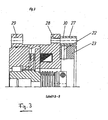
Fig. 3 eine Schnittansicht ähnlich derFig. 2 , jedoch längs Linie B-B inFig. 4 ; -
Fig. 4 eine Ansicht derFig. 2 und3 von rechts; -
Fig. 5 eine weitere vorzugsweise Ausgestaltung der ersten Ausführungsform der erfindungsgemäßen Kupplungsbremskombination; -
Fig. 6 eine weitere Ausführungsform der erfindungsgemäßen Kupplungsbremskombination, ähnlichFig. 2 und3 , jedoch mit Steckkupplung mit elastischem Stern und Klemmkasten sowie mit Lüftüberwachung; -
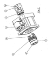
Fig. 7 eine Explosionszeichnung derFig. 6 zur besseren Darstellung der elastischen Kupplung als Steckkupplung mit elastischem Stern; -
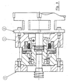
Fig. 8 eine weitere Ausführungsform der erfindungsgemäßen Kupplungsbremskombination, mit einer integrierten Überlastkupplung, welche mit der elastischen Steckkupplung verbunden ist; -
Fig. 9 ein Anwendungsbeispiel, d.h. den Anbau einer Kupplungsbremskombination an ein Gehäuse mit Spindel und einem Anbaumotor. - Die
Fig. 2 zeigt ein bevorzugtes Ausführungsbeispiel der erfindungsgemäßen Kupplungsbremskombination, deren wesentlicher Aspekt darin zu sehen ist, dass eine iuhestrombetätigte Reibungsbremse in das Verbindungsstück 3 derFig.1 integriert ist und der zugehörige Bremsrotor 8 im Inneren des Verbindungsstückes auf der Verzahnung 13 auf der zentralen Nabe 15 der Hohlwelle 16 der Abtriebsseite sitzt, wobei die Hohlwelle über einen Klemmring 14 mit einer Klemmschraube 33 mit dem nicht näher dargestellten Wellenstumpf der Abtriebsseite verbindbar ist. - Die Hohlwelle 16 der Abtriebsseite weist zur Antriebsseite hin eine axiale Verlängerung in Gestalt einer flexiblen Kupplung auf, die konkret die Form einer angeschweißten Balgkupplung 18 mit einem endständigen Klemmring 12 auf der Antriebsseite aufweist, wobei letzterer mit einer Klemmschraube 32 betätigbar ist.
- Das in
Fig. 2 die Hohlwelle 16 der Abtriebsseite und die Balgkupplung 18 der Antriebsseite vollständig einschließende äußere Gehäuse, welches dem Verbindungsstück 3 bzw. der Laterne derFig.1 entspricht, ist zugleich auch als Spulenträgergehäuse 5 für die Magnetspule 6 ausgebildet, die in bekannter Weise mit der axial verschieblichen aber undrehbaren Ankerscheibe 7 zusammenwirkt und letztere im bestromten Zustand entgegen der Kraft der Druckfedern 19 anzieht. Im stromlosen Zustand drückt die Ankerscheibe 7 aufgrund der Druckfedern 19 gegen den beidseitig mit Reibbelägen 9 versehenen Bremsrotor 8, der über die Verzahnung 13 mit der Hohlwelle 16 drehstarr aber axial verschieblich verbunden ist. Im gebremsten Zustand liegt der Rotor mit seinen Reibbelägen 9 einerseits an der Ankerscheibe 7, andererseits am Bremsflansch 10 an, der anstatt der "Laterne" (= Verbindungsstück) vorhanden ist. - Den in
Figur 2 rechtsseitigen Abschluß (anstatt der "Laterne") bildet ein konzentrisch aufgesetzter Verstellring 23, der eine Zentrierung 25 für den nicht näher dargestellten Antriebsmotor 2 aufweist. Der Verstellring weist eine radiale Bohrung 22 auf, die es ermöglicht, ein Werkzeug zum Lösen bzw. Festziehen der Klemmschraube 32 von außen in das Aggregat einzuführen. Die Verstellbarkeit des Ringes 23 in Umfangsrichtung gewährleistet, dass ein Zugriff auf die Schraube 32 immer möglich ist, unabhängig von der rein zufälligen Ruheposition des Klemmringes 12 im Stillstand des Aggregates. - In
Fig. 3 wird die Anschraubung über die Distanzhülsen 27 mit Bohrung 30 an das Gewinde 28 im Spulenträger 5 gezeigt. Der Verstellring 23 ist etwas kürzer als die Distanzhülse 27, so daß im angebauten Zustand der Verstellring 23 verdreht werden kann, um die Bohrung 22 im Verstellring 23 in jede beliebige Position bringen zu können, um an die Klemmschraube 32 an der Motorseite des Klemmringes 12 auf der Motorseite hinzukommen. - In
Figur 4 wird in der Seitenansicht die Bohrung 22 im Verstellring 23 strichliert angedeutet, durch welche man an die Klemmschraube 32 hinkommt. - Die in
Figur 5 gezeigten, auf dem Umfang des Verstellringes 23 gleichmäßig verteilten drei oder mehr Gewindestifte 38 dienen dazu, dass bei Verkantung oder exzentrischem Einführen der Motorwelle 17 in die Balgkupplung 18 der Balg nicht verdrückt und beschädigt wird. Nachdem die Gewindestifte 38 in die Ringnut 39 der Balgkupplung 18 hinein ragen, kann der Balg weder beim Einschieben noch beim Herausziehen der Welle 17 zusammengedrückt bzw. überdehnt werden. Der Spalt 40 zwischen dem Spulenträgergehäuse 5 und der Balgkupplung 18 dient zusätzlich zur radialen Begrenzung der Verlagerungsmöglichkeit , um auch hier keinen unnötigen, übermäßigen Radialversatz zu bekommen, welcher bei der Kupplung bleibende Schäden hinterlassen könnte. Ein weiterer Vorteil ist dadurch auch für den Transport der gesamten Kupplungs-Brems-Kombination gegeben. - In
Figur 6 wird eine Alternativform mit der Steckkupplung 41 mit elastischem Stern 42 gezeigt. Die Klemmung erfolgt ebenfalls mit einer Klemmschraube 32. Auf der Abtriebsseite 2 wird die Klemmung der Nabe 15 über einen Spannring 43 vorgenommen, welcher über Spannschrauben 44 angezogen wird. In einem Abdichtungsflansch 45 befindet sich ein Dichtring 46, welcher die Reibbeläge 9 vor Schmutz und Öl schützt. - Im Anschlußkasten 47 befindet sich eine Lüftüberwachung 48 (Mikroschalter), welcher den Zustand der Bremse (frei oder gebremst) anzeigt.
- In
Figur 7 wird nochmals in übersichtlicher Form die Ausführungsform mit der Steckkupplung 41 mit elastischem Stern 42 in Explosionsdarstellung gezeigt. Mit den Spannschrauben 44 wird der Spannring 43 angezogen und somit die Abtriebswelle (z. B. Getriebe, Spindel oder ähnliches) mit der Kupplung verbunden. -
Figur 8 zeigt eine Ausführungsform, bei welcher die Steckkupplung 41 mit einer Überlastkupplung .49 verbunden ist, welche bei Überlastung ausrastet und eine Axialbewegung ausführt. Diese Axialbewegung wird mit einem Initiator 50 aufgenommen, und der Antriebsmotor wird abgeschaltet. Somit wird der ganze Antrieb vor Überlast geschützt. - In
Figur 9 wird der Anbau dargestellt, bei welchem der Antriebsmotor 2 mit seinem Wellenstumpf und Zentrierung an die Kupplungsbremskombination angebaut wird. Die Kupplungsbremskombination wird dann weiter an ein Gehäuse mit Spindel oder Getriebe angebaut. Das Verbindungsstück 3 nach dem Stand der Technik inFigur 1 entfällt und die erfindungsgemäße Kupplungsbremskombination kommt im Austausch dazwischen. Ein wesentlicher Vorteil liegt darin, daß mit dieser Konstruktion vorhandene Maschinen einflach durch den Wegfall der herkömmlichen "Laterne" 3 und der Kupplung 4 und durch den Austausch mit einer Kupplungsbremskombination, ohne Anapassungsarbeiten, baugleich ausgetauscht werden können. Dies bedeutet keine zusätzlichen Kosten und gewährleistet die zusätzliche Sicherheit durch eine ruhestrombetätigte Bremse. - Die Bremse arbeitet nach dem bekannten Ruhestromprinzip. Es wird eine Spannung auf die Magnetspule 6 gegeben, welche sich im Spulenträgergehäuse 5 befindet. Dadurch wird die Ankerscheibe 7 axial gegen den Druck der Druckfedern 19 angezogen, wobei die Drehmomentübertragung über die Bolzen 20 erfolgt. Somit kann der Rotor 8 mit den beiden Reibbelägen 9 über die Verzahnung 13 auf der Nabe 15 folgen. Diese kann frei umdrehen. Wird der Strom weggenommen, fällt die Ankerscheibe über den Federdruck 19 gegen die beiden Reibbeläge 9 ein und die Nabe 15 wird abgebremst.
- Die Motorwelle 17, welche von rechts in
Fig. 2 in die Balgkupplung 18 eingeschoben wird, kann über den Klemmring 12 und die Schraube 32 geklemmt werden. Somit erfolgt die Drehmomentübertragung von der Motorwelle 17 auf die Balgkupplung 18 oder die Steckkupplung 41 mit elastischem Stern 42, welche mit der Nabe 15 verbunden ist. Durch den Klemmring 14 kann ein beliebiger anzutreibender Wellenstumpf, wie z.B. ein Getriebewellenstumpf oder ein Spindelwellenstumpf in die Hohlwelle 16 eingeschoben werden. Im Inneren der Hohlwelle 16 ist vorzugsweise ein Anschlag 31 ausgebildet, damit die Welle nicht zu weit eingeschoben wird. Mit dem Klemmring 14 und der Schraube 33 wird dann die sogenannte Abtriebswelle (Getriebe oder Spindelwelle) geklemmt und es erfolgt die gewünschte Drehmomentübertragung von der Antriebsseite zu der Abtriebsseite. - Bei der Montage wird zuerst die Getriebewelle geklemmt, was über die Bohrung 21 mit einem Innensechskantschlüssel auf die Schraube 33 erfolgen kann. Über die Außenzentrierung 26 wird die Kupplungs-Brems-Kombination am Getriebe oder einem Gehäuse angebaut und über die Bohrung 29 an vier Stellen befestigt. Die Verbindungsschraube 11 dient nur dazu, das Gehäuse 5 an dem Bremsflansch 10 zu fixieren.
- Die Motorwelle 17 wird in die Balgkupplung hinein geschoben und anschließend wird über die Bohrung 22 der Klemmring 12 mit der Innensechskantschraube 32 auf der Motorwelle geklemmt. Der Motor wird über die Zentrierung 25 auf dem Verstellring 23 fixiert und über vier Abstandsbuchsen 27 mit einer Bohrung 30 mit Schrauben am Gewinde 28 befestigt.
- Der Verstellring 23 dient dazu, dass bei einem Motorausfall dieser Ring in eine beliebige Drehstellung gedreht werden kann, so dass die Bohrung 22 über der Schraube 32 des Klemmringes 12 steht, um dann die Motorwelle 17 in jeder beliebigen Lage lösen zu können und sie axial aus der Kupplung herausziehen zu können. Mit dieser Ausgestaltung wird eine komplett geschlossene Kupplungs-Brems-Kombination geschaffen, bei der trotzdem in jeder beliebigen Lage der Motor an- bzw. abgebaut werden kann. Dies ist wichtig bei Motordefekten, weil dann der Motor nicht mehr funktioniert und nicht mehr in eine bestimmte "Demontage-Position" gedreht werden kann.
- Bei der Ausführung gemäß
Fig. 6 und7 besteht der Vorteil einer Steckkupplung gegenüber einer Balgkupplung, daß der Zwischenring 23, welcher verstellbar ist, entfallen kann und die Kupplungsbremskombination komplett an das Gehäuse angebaut werden kann und erst anschließend der Motor mit der Steckkupplung 41 und dem elastischen Stern 42 in die Kupplungsbremskombination eingeführt wird und der Motor anschließend an der Kupplungsbremskombination befestigt wird. Eine Demontage ist in jeder beliebigen Lage des Motors möglich, da die Steckkupplung steckbar ist und der Motor mit der Kupplung 41 und 42 herausgezogen werden kann. -
- 1
- Getriebe/Spindel o.ä. (= Abtrieb)
- 2
- Motor
- 3
- Laterne zwischen Motor und Getriebe (= Verbindungsstück)
- 4
- Kupplung
- 5
- Spulenträgergehäuse
- 6
- Magnetspule
- 7
- Ankerscheibe
- 8
- Rotor
- 9
- Reibbeläge
- 10
- Bremsflansch
- 11
- Verbindungsschraube
- 12
- Klemmring Motorseite
- 13
- Verzahnung
- 14
- Klemmring Getriebeseite
- 15
- Nabe (mit Verzahnung 13)
- 16
- Hohlwelle Getriebeseite
- 17
- Motorwelle
- 18
- Balgkupplung
- 19
- Federn (Schraubenfedern)
- 20
- Bolzen
- 21
- Bohrung im Bremsflansch
- 22
- Bohrung im Verstellring
- 23
- Verstellring
- 24
- Zentrierung Spulenträger (5)
- 25
- Zentrierung Verstellring für Motor
- 26
- Außenzentrierung Bremsflansch
- 27
- Distanzhülsen
- 28
- Gewinde im Spulenträger (5)
- 29
- Durchgangsbohrung im Spulenträger (5)
- 30
- Bohrung Distanzhülse
- 31
- Anschlag Hohlwelle (16)
- 32
- Klemmschraube Motorseite
- 33
- Klemmschraube Getriebeseite
- 34
- Wellenstumpf
- 35
- Lagerung
- 36
- Hohlwelle für Motorwelle
- 37
- Klemmung für Motorwelle
- 38
- Gewindestifte im Verstellring (23)
- 39
- Rille im Klemmring (12)
- 40
- Zentrierung (radiale Begrenzung)
- 41
- Steckkuppklung
- 42
- Elastischer Stern
- 43
- Spannring (konisch)
- 44
- Spannschrauben
- 45
- Abdichtungsflansch
- 46
- Dichtring
- 47
- Anschlußkasten
- 48
- Lüftüberwachung (Mikroschalter).
- 49
- Überlastkupplung
- 50
- Initiator (Sensor)
Claims (11)
- Antriebs-Abtriebs-Aggregat mit Kupplungsbremskombination,
bei dem das Aggregat als Verbindungsstück (3) zwischen Motor (2) und Abtrieb (1) mit integrierter ruhestrombetätigter Federdruckbremse und mit einer zentralen Nabe (15) zwischen Motor (2) und Abtrieb (1) ausgebildet ist,
wobei die Federdruckbremse auf dem Abtrieb (1) angeordnet und das Aggregat so ausgebildet ist, dass die beiden Wellenspiegel vom Motor (2) und Abtrieb (1) in der zentralen Nabe (15) unmittelbar aneinander liegen, damit die kürzest mögliche Baulänge des kompletten Aggregats erreicht wird,
wobei der Bremsrotor (8) der Federdruckbremse im Inneren des Verbindungsstückes (3) auf der Verzahnung (13) der zentralen Nabe (15) der Hohlwelle (16) des Antriebs (1) sitzt,
und wobei zur Drehmomentübertragung vom Motor (2) auf die Nabe (15) eine elastische Kupplung vorgesehen ist, die im Durchmesser so klein ist, dass sie radial ins Zentrum der Bremse passt und die beiden Wellenspiegel so nah wie möglich aneinander liegen. - Aggregat nach Anspruch 1, dadurch gekennzeichnet, dass die elastische Kupplung als Balgkupplung (18) mit Klemmring (12) ausgebildet ist.
- Aggregat nach Anspruch 2, dadurch gekennzeichnet, dass ein in seiner Drehwinkelstellung einstellbarer Verstellring (23) vorgesehen ist, damit in jeder beliebigen Drehstellung des Klemmringes (12) der Abtriebsseite die Möglichkeit besteht, über die radiale Bohrung (22) die Klemmschraube (32) zu lösen, um bei einem Defekt einen neuen Motor einzubauen.
- Aggregat nach Anspruch 2 oder 3, dadurch gekennzeichnet, dass der Klemmring (12) mit einer Rille (Nut 39) ausgebildet ist, in welche mehrere auf dem Umfang verteilte Gewindestifte (38) hineinragen, die den Balg für die Demontage und Montage der Motorwelle (17) axial festlegen, damit er bei der Montage nicht zerdrückt und überdehnt wird.
- Aggregat nach einem der Ansprüche 2 bis 4, dadurch gekennzeichnet, dass zusätzlich ein Spalt (40) zwischen Spulenträgergehäuse (5) und Klemmring (12) vorhanden ist derart, dass der Spalt (40) eine angemessene radiale Fixierung der Balgkupplung bewirkt, der somit gegen zu starke radiale Verlagerungen gesichert ist.
- Aggregat nach Anspruch 1, dadurch gekennzeichnet, dass die elastische Kupplung der Nabe (15) als eine Steckkupplung (41) mit elastischem Stern (42) ausgebildet ist.
- Aggregat nach Anspruch 6, dadurch gekennzeichnet, dass die Nabe (15) mit einem Spannring (43) ausgebildet ist.
- Aggregat nach einem der Ansprüche 6 oder 7, dadurch gekennzeichnet, dass im Bremsflansch (10) ein Abdichtungsflansch (45) eingesetzt wird, welcher einen Dichtring beinhaltet und zum Spannring (43) eine Abdichtung bildet, um die Reibbeläge (9) vor Schmutz und Öl zu schützen.
- Aggregat nach einem der Ansprüche 1 bis 8, dadurch gekennzeichnet, dass an die elastische Kupplung in Gestalt einer Balgkupplung oder Steckkupplung mit elastischem Stern eine Überlastkupplung (49) angebaut wird, welche über einen Initiator/Sensor (50) bei Überlastung den Antrieb abschaltet.
- Aggregat nach einen der Ansprüche 1 bis 9, dadurch gekennzeichnet, dass für ein redundantes Bremssystem eine zweite Bremse mit Magnetspule, Ankerscheibe und Rotor in die Kupplungsbremskombination eingefügt wird.
- Aggregat nach einem der Ansprüche 1 bis 10, dadurch gekennzeichnet, dass an die Kupplungsbremskombination ein Anschlusskasten (47) angebracht wird, in welchem sich eine Lüftüberwachung (48) mittels eines Mikroschalters befindet, welche durch die Bewegung der Ankerscheibe (7) den Mikroschalter (48) betätigt und ein Signal gibt, ob die Bremse frei oder gebremst ist.
Applications Claiming Priority (2)
| Application Number | Priority Date | Filing Date | Title |
|---|---|---|---|
| DE10335639A DE10335639A1 (de) | 2003-08-04 | 2003-08-04 | Kupplungsbremskombination |
| PCT/EP2004/008654 WO2005017384A1 (de) | 2003-08-04 | 2004-08-02 | Kupplungsbremskombination |
Publications (2)
| Publication Number | Publication Date |
|---|---|
| EP1651883A1 EP1651883A1 (de) | 2006-05-03 |
| EP1651883B1 true EP1651883B1 (de) | 2009-03-11 |
Family
ID=34111895
Family Applications (1)
| Application Number | Title | Priority Date | Filing Date |
|---|---|---|---|
| EP04741352A Expired - Lifetime EP1651883B1 (de) | 2003-08-04 | 2004-08-02 | Antriebs-Abtriebs-Aggregat mit Kupplungsbremskombination |
Country Status (6)
| Country | Link |
|---|---|
| US (1) | US20070107998A1 (de) |
| EP (1) | EP1651883B1 (de) |
| CN (2) | CN101592202B (de) |
| AT (1) | ATE425383T1 (de) |
| DE (2) | DE10335639A1 (de) |
| WO (1) | WO2005017384A1 (de) |
Families Citing this family (18)
| Publication number | Priority date | Publication date | Assignee | Title |
|---|---|---|---|---|
| DE10330307A1 (de) * | 2003-07-04 | 2005-01-20 | Chr. Mayr Gmbh + Co Kg | Bremseinheit für Zahnstangenantrieb |
| DE102006009876B3 (de) * | 2006-03-03 | 2007-10-18 | Kendrion Binder Magnete Gmbh | Elektromagnetisch öffnende Federdruckbremse mit einer Lüfteinrichtung und einem Mikroschalter |
| DE102008033270A1 (de) * | 2008-07-15 | 2010-01-21 | Schaeffler Kg | Elektromechanischer Aktuator, insbesondere für einen Wankstabilisator eines Kraftfahrzeugs |
| DE102011111185A1 (de) * | 2011-08-25 | 2013-02-28 | Neugart Gmbh | Antriebseinheit mit einem Elektromotor |
| CN104832570A (zh) * | 2014-02-12 | 2015-08-12 | 上海三嵩精密机电有限公司 | 电磁刹车装置 |
| CN105317975B (zh) * | 2014-07-31 | 2017-10-20 | 上海千彩节能环保科技有限公司 | 一种弹性连接装置 |
| DE102015005360B3 (de) * | 2015-04-28 | 2016-06-23 | Sew-Eurodrive Gmbh & Co Kg | Getriebesystem |
| CN107269065B (zh) * | 2017-05-27 | 2020-04-03 | 辽宁工程技术大学 | 一种立体车库升降横移层车位升降传动装置 |
| US10288133B1 (en) * | 2017-12-06 | 2019-05-14 | Warner Electric Technology Llc | Rotational coupling device having means for sealing the interface between the armature and the electromagnet |
| US10612610B2 (en) * | 2018-04-12 | 2020-04-07 | Warner Electric Technology Llc | Bistable Brake |
| EP3604839A1 (de) | 2018-08-03 | 2020-02-05 | Ondal Medical Systems GmbH | Lageranordnung |
| US11174908B2 (en) * | 2019-04-04 | 2021-11-16 | Warner Electric Technology Llc | Miniature brake and method of assembly |
| DE102019119780A1 (de) * | 2019-07-22 | 2021-01-28 | Breuell & Hilgenfeldt GmbH | Kupplungselement |
| CN110966318B (zh) * | 2019-12-06 | 2021-04-27 | 珠海格力电器股份有限公司 | 一种分体式制动器及电机 |
| EP3865725B1 (de) * | 2020-02-17 | 2024-03-27 | Ratier-Figeac SAS | Drehmomentbegrenzer |
| DE102022004298A1 (de) * | 2021-11-30 | 2023-06-01 | Sew-Eurodrive Gmbh & Co Kg | Antrieb, aufweisend ein Getriebe mit einem Getriebegehäuse, eine elektromagnetisch betätigbare Bremsanordnung und einen Elektromotor |
| CN114776719B (zh) * | 2022-05-07 | 2024-08-20 | 太仓博正数控科技有限公司 | 一种防过载安全型数控机床联轴器 |
| CN115234587A (zh) * | 2022-08-01 | 2022-10-25 | 成都瑞迪智驱科技股份有限公司 | 一种扭矩可调的双面摩擦得电制动式电磁制动器 |
Family Cites Families (18)
| Publication number | Priority date | Publication date | Assignee | Title |
|---|---|---|---|---|
| US2217464A (en) * | 1938-11-22 | 1940-10-08 | Westinghouse Electric & Mfg Co | Magnetically operated disk-type brake |
| US2649941A (en) * | 1948-10-29 | 1953-08-25 | Doebeli Albert | Electromagnetically actuated friction coupling with servo-action |
| US2943464A (en) * | 1958-04-09 | 1960-07-05 | Fred W Voges | Aligning flexible coupling |
| FR1399381A (fr) * | 1964-06-24 | 1965-05-14 | Norman Developments Ltd | Perfectionnements aux dispositifs de freins à embrayage |
| FR1431052A (fr) * | 1965-01-28 | 1966-03-11 | Perfectionnements aux freins, embrayages et limiteurs de couple | |
| US3338349A (en) * | 1966-11-17 | 1967-08-29 | Warner Electric Brake & Clutch | Electric motor mounted magnetic friction brake |
| US3831724A (en) * | 1972-11-06 | 1974-08-27 | Warner Electric Brake & Clutch | Clutch and coupling unit |
| US3983971A (en) * | 1974-05-22 | 1976-10-05 | Kabushiki Kaisha Meidensha | Brake device |
| US4488626A (en) * | 1981-08-06 | 1984-12-18 | Handke Kenneth E | Torque transmitting apparatus and method |
| US5172798A (en) * | 1992-06-08 | 1992-12-22 | Easom Engineering And Manufacturing Corporation | Electrical actuation system for a drive |
| DE19614945A1 (de) * | 1996-04-16 | 1997-10-23 | Zahnradfabrik Friedrichshafen | Elektromagnetische Federdruckbremse oder -kupplung |
| DE19733169B4 (de) * | 1997-07-31 | 2005-06-16 | Chr. Mayr Gmbh & Co. Kg | Elektromagnetisch gelüftete Reibungs-Sicherheitsbremse mit zwei unabhängigen Bremskreisen |
| DE19812223A1 (de) * | 1998-03-19 | 1999-09-23 | Mayr Christian Gmbh & Co Kg | Drehsteife, spielfreie, elastische Metallbalgkupplung zur drehmomentübertragenden Verbindung zweier Wellen |
| US6315088B1 (en) * | 1999-08-24 | 2001-11-13 | Warner Electric Technology, Inc. | Spring-set electromagnetically released brake |
| DE10051434C2 (de) * | 2000-09-13 | 2003-01-02 | Sew Eurodrive Gmbh & Co | Baureihe von Adaptervorrichtungen und Adaptervorrichtung |
| US6675939B2 (en) * | 2001-01-31 | 2004-01-13 | Inertia Dynamics, Inc. | Elevator brake assembly |
| DE20105746U1 (de) * | 2001-04-02 | 2001-05-31 | Chr. Mayr Gmbh + Co Kg, 87665 Mauerstetten | Kupplungs-Bremskombination |
| JP3926695B2 (ja) * | 2002-07-24 | 2007-06-06 | 本田技研工業株式会社 | 電磁ブレーキ |
-
2003
- 2003-08-04 DE DE10335639A patent/DE10335639A1/de not_active Withdrawn
-
2004
- 2004-08-02 CN CN2009101505290A patent/CN101592202B/zh not_active Expired - Lifetime
- 2004-08-02 WO PCT/EP2004/008654 patent/WO2005017384A1/de not_active Ceased
- 2004-08-02 AT AT04741352T patent/ATE425383T1/de not_active IP Right Cessation
- 2004-08-02 EP EP04741352A patent/EP1651883B1/de not_active Expired - Lifetime
- 2004-08-02 US US10/565,176 patent/US20070107998A1/en not_active Abandoned
- 2004-08-02 DE DE502004009148T patent/DE502004009148D1/de not_active Expired - Lifetime
- 2004-08-02 CN CNB2004800192453A patent/CN100545480C/zh not_active Expired - Fee Related
Also Published As
| Publication number | Publication date |
|---|---|
| US20070107998A1 (en) | 2007-05-17 |
| ATE425383T1 (de) | 2009-03-15 |
| EP1651883A1 (de) | 2006-05-03 |
| DE10335639A1 (de) | 2005-03-03 |
| CN100545480C (zh) | 2009-09-30 |
| CN101592202B (zh) | 2011-11-09 |
| WO2005017384A1 (de) | 2005-02-24 |
| CN1816704A (zh) | 2006-08-09 |
| CN101592202A (zh) | 2009-12-02 |
| DE502004009148D1 (de) | 2009-04-23 |
Similar Documents
| Publication | Publication Date | Title |
|---|---|---|
| EP1651883A1 (de) | Kupplungsbremskombination | |
| DE69324123T2 (de) | Elektrisches Hebezeug und Zugvorrichtung | |
| EP0064763B1 (de) | Antrieb, insbesondere Verstellantrieb für Kraftfahrzeuge | |
| EP1488121A1 (de) | Vorrichtung zur kopplung einer gehauseanordnung einer kopplungseinrichtung mit einer rotoranordnung einer elektromaschine | |
| DE19815962A1 (de) | Elektrische Maschine, insbesondere für Fahrstuhlantrieb | |
| EP1596488B1 (de) | Antriebsmotor mit integrierten Wellenverbindungselementen | |
| CH665065A5 (de) | Mit reibungsbremse ausgeruesteter elektrischer motor. | |
| DE19632917A1 (de) | Bremsenjustiermechanismus | |
| EP3805059B1 (de) | Scheibenbremse mit einem elektromechanischen aktuator, insbesondere einem elektromechanischen parkbremsaktuator | |
| CH659866A5 (de) | Stirnzahnkupplung mit elektromagnetischer betaetigung. | |
| DE60205878T2 (de) | Brems-kupplung anordnung | |
| DE4225158A1 (de) | Elektromaschinensystem | |
| EP0729912A1 (de) | Kettezug mit einer durch die Bremse verstellbaren Kupplung | |
| EP1422187B1 (de) | Schwenkantrieb | |
| EP0729913B1 (de) | Kettenzug mit auf beide Seiten der Kupplung wirkender Bremse | |
| DE102012205995A1 (de) | Schräg verzahntes Getriebe, elektrische Maschine | |
| DE1503362C3 (de) | Haltebremse für einen Drehkolbenmotor | |
| WO1999047405A1 (de) | Elektrische lenkhilfe | |
| EP2772647B1 (de) | Drehstellantrieb | |
| DE102021104468A1 (de) | Verfahren zur Montage einer Axialflussmaschine in ein Gehäuse sowie Axialflussmaschine und Roboter | |
| EP3770454A1 (de) | Anordnung mit einer wellenkupplung und einem bremsrotor | |
| EP3260722B1 (de) | Bremse und antriebssystem mit bremse | |
| EP0786852B1 (de) | Elektrischer Antrieb | |
| DE3202420A1 (de) | Schrauber, vorzugsweise druckluftschrauber | |
| DE2215053A1 (de) | Sicherheits-rutschkupplung |
Legal Events
| Date | Code | Title | Description |
|---|---|---|---|
| PUAI | Public reference made under article 153(3) epc to a published international application that has entered the european phase |
Free format text: ORIGINAL CODE: 0009012 |
|
| 17P | Request for examination filed |
Effective date: 20060127 |
|
| AK | Designated contracting states |
Kind code of ref document: A1 Designated state(s): AT BE BG CH CY CZ DE DK EE ES FI FR GB GR HU IE IT LI LU MC NL PL PT RO SE SI SK TR |
|
| DAX | Request for extension of the european patent (deleted) | ||
| 17Q | First examination report despatched |
Effective date: 20070927 |
|
| GRAP | Despatch of communication of intention to grant a patent |
Free format text: ORIGINAL CODE: EPIDOSNIGR1 |
|
| RTI1 | Title (correction) |
Free format text: DRIVE-DRIVEN-UNIT WITH COUPLING/BRAKE COMBINATION |
|
| GRAS | Grant fee paid |
Free format text: ORIGINAL CODE: EPIDOSNIGR3 |
|
| GRAA | (expected) grant |
Free format text: ORIGINAL CODE: 0009210 |
|
| AK | Designated contracting states |
Kind code of ref document: B1 Designated state(s): AT BE BG CH CY CZ DE DK EE ES FI FR GB GR HU IE IT LI LU MC NL PL PT RO SE SI SK TR |
|
| REG | Reference to a national code |
Ref country code: GB Ref legal event code: FG4D Free format text: NOT ENGLISH |
|
| REG | Reference to a national code |
Ref country code: CH Ref legal event code: EP |
|
| REG | Reference to a national code |
Ref country code: IE Ref legal event code: FG4D Free format text: LANGUAGE OF EP DOCUMENT: GERMAN |
|
| REF | Corresponds to: |
Ref document number: 502004009148 Country of ref document: DE Date of ref document: 20090423 Kind code of ref document: P |
|
| PG25 | Lapsed in a contracting state [announced via postgrant information from national office to epo] |
Ref country code: SI Free format text: LAPSE BECAUSE OF FAILURE TO SUBMIT A TRANSLATION OF THE DESCRIPTION OR TO PAY THE FEE WITHIN THE PRESCRIBED TIME-LIMIT Effective date: 20090311 Ref country code: FI Free format text: LAPSE BECAUSE OF FAILURE TO SUBMIT A TRANSLATION OF THE DESCRIPTION OR TO PAY THE FEE WITHIN THE PRESCRIBED TIME-LIMIT Effective date: 20090311 Ref country code: NL Free format text: LAPSE BECAUSE OF FAILURE TO SUBMIT A TRANSLATION OF THE DESCRIPTION OR TO PAY THE FEE WITHIN THE PRESCRIBED TIME-LIMIT Effective date: 20090311 |
|
| NLV1 | Nl: lapsed or annulled due to failure to fulfill the requirements of art. 29p and 29m of the patents act | ||
| PG25 | Lapsed in a contracting state [announced via postgrant information from national office to epo] |
Ref country code: SE Free format text: LAPSE BECAUSE OF FAILURE TO SUBMIT A TRANSLATION OF THE DESCRIPTION OR TO PAY THE FEE WITHIN THE PRESCRIBED TIME-LIMIT Effective date: 20090611 Ref country code: PL Free format text: LAPSE BECAUSE OF FAILURE TO SUBMIT A TRANSLATION OF THE DESCRIPTION OR TO PAY THE FEE WITHIN THE PRESCRIBED TIME-LIMIT Effective date: 20090311 |
|
| REG | Reference to a national code |
Ref country code: IE Ref legal event code: FD4D |
|
| PG25 | Lapsed in a contracting state [announced via postgrant information from national office to epo] |
Ref country code: EE Free format text: LAPSE BECAUSE OF FAILURE TO SUBMIT A TRANSLATION OF THE DESCRIPTION OR TO PAY THE FEE WITHIN THE PRESCRIBED TIME-LIMIT Effective date: 20090311 Ref country code: ES Free format text: LAPSE BECAUSE OF FAILURE TO SUBMIT A TRANSLATION OF THE DESCRIPTION OR TO PAY THE FEE WITHIN THE PRESCRIBED TIME-LIMIT Effective date: 20090622 Ref country code: IE Free format text: LAPSE BECAUSE OF FAILURE TO SUBMIT A TRANSLATION OF THE DESCRIPTION OR TO PAY THE FEE WITHIN THE PRESCRIBED TIME-LIMIT Effective date: 20090311 Ref country code: CZ Free format text: LAPSE BECAUSE OF FAILURE TO SUBMIT A TRANSLATION OF THE DESCRIPTION OR TO PAY THE FEE WITHIN THE PRESCRIBED TIME-LIMIT Effective date: 20090311 Ref country code: PT Free format text: LAPSE BECAUSE OF FAILURE TO SUBMIT A TRANSLATION OF THE DESCRIPTION OR TO PAY THE FEE WITHIN THE PRESCRIBED TIME-LIMIT Effective date: 20090824 |
|
| PG25 | Lapsed in a contracting state [announced via postgrant information from national office to epo] |
Ref country code: RO Free format text: LAPSE BECAUSE OF FAILURE TO SUBMIT A TRANSLATION OF THE DESCRIPTION OR TO PAY THE FEE WITHIN THE PRESCRIBED TIME-LIMIT Effective date: 20090311 Ref country code: SK Free format text: LAPSE BECAUSE OF FAILURE TO SUBMIT A TRANSLATION OF THE DESCRIPTION OR TO PAY THE FEE WITHIN THE PRESCRIBED TIME-LIMIT Effective date: 20090311 |
|
| PLBE | No opposition filed within time limit |
Free format text: ORIGINAL CODE: 0009261 |
|
| STAA | Information on the status of an ep patent application or granted ep patent |
Free format text: STATUS: NO OPPOSITION FILED WITHIN TIME LIMIT |
|
| PG25 | Lapsed in a contracting state [announced via postgrant information from national office to epo] |
Ref country code: DK Free format text: LAPSE BECAUSE OF FAILURE TO SUBMIT A TRANSLATION OF THE DESCRIPTION OR TO PAY THE FEE WITHIN THE PRESCRIBED TIME-LIMIT Effective date: 20090311 Ref country code: BG Free format text: LAPSE BECAUSE OF FAILURE TO SUBMIT A TRANSLATION OF THE DESCRIPTION OR TO PAY THE FEE WITHIN THE PRESCRIBED TIME-LIMIT Effective date: 20090611 |
|
| 26N | No opposition filed |
Effective date: 20091214 |
|
| BERE | Be: lapsed |
Owner name: CHR. MAYR G.M.B.H. & CO. KG Effective date: 20090831 |
|
| PG25 | Lapsed in a contracting state [announced via postgrant information from national office to epo] |
Ref country code: MC Free format text: LAPSE BECAUSE OF NON-PAYMENT OF DUE FEES Effective date: 20090831 |
|
| REG | Reference to a national code |
Ref country code: CH Ref legal event code: PL |
|
| PG25 | Lapsed in a contracting state [announced via postgrant information from national office to epo] |
Ref country code: LI Free format text: LAPSE BECAUSE OF NON-PAYMENT OF DUE FEES Effective date: 20090831 Ref country code: CH Free format text: LAPSE BECAUSE OF NON-PAYMENT OF DUE FEES Effective date: 20090831 |
|
| PG25 | Lapsed in a contracting state [announced via postgrant information from national office to epo] |
Ref country code: BE Free format text: LAPSE BECAUSE OF NON-PAYMENT OF DUE FEES Effective date: 20090831 |
|
| PG25 | Lapsed in a contracting state [announced via postgrant information from national office to epo] |
Ref country code: GR Free format text: LAPSE BECAUSE OF FAILURE TO SUBMIT A TRANSLATION OF THE DESCRIPTION OR TO PAY THE FEE WITHIN THE PRESCRIBED TIME-LIMIT Effective date: 20090612 |
|
| PG25 | Lapsed in a contracting state [announced via postgrant information from national office to epo] |
Ref country code: AT Free format text: LAPSE BECAUSE OF NON-PAYMENT OF DUE FEES Effective date: 20090802 |
|
| PG25 | Lapsed in a contracting state [announced via postgrant information from national office to epo] |
Ref country code: LU Free format text: LAPSE BECAUSE OF NON-PAYMENT OF DUE FEES Effective date: 20090802 |
|
| PG25 | Lapsed in a contracting state [announced via postgrant information from national office to epo] |
Ref country code: HU Free format text: LAPSE BECAUSE OF FAILURE TO SUBMIT A TRANSLATION OF THE DESCRIPTION OR TO PAY THE FEE WITHIN THE PRESCRIBED TIME-LIMIT Effective date: 20090912 |
|
| PG25 | Lapsed in a contracting state [announced via postgrant information from national office to epo] |
Ref country code: TR Free format text: LAPSE BECAUSE OF FAILURE TO SUBMIT A TRANSLATION OF THE DESCRIPTION OR TO PAY THE FEE WITHIN THE PRESCRIBED TIME-LIMIT Effective date: 20090311 |
|
| PG25 | Lapsed in a contracting state [announced via postgrant information from national office to epo] |
Ref country code: CY Free format text: LAPSE BECAUSE OF FAILURE TO SUBMIT A TRANSLATION OF THE DESCRIPTION OR TO PAY THE FEE WITHIN THE PRESCRIBED TIME-LIMIT Effective date: 20090311 |
|
| REG | Reference to a national code |
Ref country code: FR Ref legal event code: PLFP Year of fee payment: 13 |
|
| REG | Reference to a national code |
Ref country code: FR Ref legal event code: PLFP Year of fee payment: 14 |
|
| REG | Reference to a national code |
Ref country code: FR Ref legal event code: PLFP Year of fee payment: 15 |
|
| REG | Reference to a national code |
Ref country code: DE Ref legal event code: R084 Ref document number: 502004009148 Country of ref document: DE |
|
| REG | Reference to a national code |
Ref country code: GB Ref legal event code: 746 Effective date: 20221205 |
|
| PGFP | Annual fee paid to national office [announced via postgrant information from national office to epo] |
Ref country code: IT Payment date: 20230222 Year of fee payment: 20 |
|
| REG | Reference to a national code |
Ref country code: DE Ref legal event code: R082 Ref document number: 502004009148 Country of ref document: DE Representative=s name: MEISSNER BOLTE PATENTANWAELTE RECHTSANWAELTE P, DE |
|
| PGFP | Annual fee paid to national office [announced via postgrant information from national office to epo] |
Ref country code: GB Payment date: 20230824 Year of fee payment: 20 |
|
| PGFP | Annual fee paid to national office [announced via postgrant information from national office to epo] |
Ref country code: FR Payment date: 20230821 Year of fee payment: 20 Ref country code: DE Payment date: 20230803 Year of fee payment: 20 |
|
| REG | Reference to a national code |
Ref country code: DE Ref legal event code: R071 Ref document number: 502004009148 Country of ref document: DE |
|
| REG | Reference to a national code |
Ref country code: GB Ref legal event code: PE20 Expiry date: 20240801 |
|
| PG25 | Lapsed in a contracting state [announced via postgrant information from national office to epo] |
Ref country code: GB Free format text: LAPSE BECAUSE OF EXPIRATION OF PROTECTION Effective date: 20240801 |
|
| PG25 | Lapsed in a contracting state [announced via postgrant information from national office to epo] |
Ref country code: GB Free format text: LAPSE BECAUSE OF EXPIRATION OF PROTECTION Effective date: 20240801 |