EP1650488A1 - Lamp, especially for general illumination, designed for mains current. - Google Patents
Lamp, especially for general illumination, designed for mains current. Download PDFInfo
- Publication number
- EP1650488A1 EP1650488A1 EP04024832A EP04024832A EP1650488A1 EP 1650488 A1 EP1650488 A1 EP 1650488A1 EP 04024832 A EP04024832 A EP 04024832A EP 04024832 A EP04024832 A EP 04024832A EP 1650488 A1 EP1650488 A1 EP 1650488A1
- Authority
- EP
- European Patent Office
- Prior art keywords
- bayonet
- power plug
- module
- lamp
- connection
- Prior art date
- Legal status (The legal status is an assumption and is not a legal conclusion. Google has not performed a legal analysis and makes no representation as to the accuracy of the status listed.)
- Granted
Links
Images


Classifications
-
- F—MECHANICAL ENGINEERING; LIGHTING; HEATING; WEAPONS; BLASTING
- F21—LIGHTING
- F21S—NON-PORTABLE LIGHTING DEVICES; SYSTEMS THEREOF; VEHICLE LIGHTING DEVICES SPECIALLY ADAPTED FOR VEHICLE EXTERIORS
- F21S8/00—Lighting devices intended for fixed installation
- F21S8/03—Lighting devices intended for fixed installation of surface-mounted type
- F21S8/033—Lighting devices intended for fixed installation of surface-mounted type the surface being a wall or like vertical structure, e.g. building facade
- F21S8/035—Lighting devices intended for fixed installation of surface-mounted type the surface being a wall or like vertical structure, e.g. building facade by means of plugging into a wall outlet, e.g. night light
-
- H—ELECTRICITY
- H01—ELECTRIC ELEMENTS
- H01R—ELECTRICALLY-CONDUCTIVE CONNECTIONS; STRUCTURAL ASSOCIATIONS OF A PLURALITY OF MUTUALLY-INSULATED ELECTRICAL CONNECTING ELEMENTS; COUPLING DEVICES; CURRENT COLLECTORS
- H01R33/00—Coupling devices specially adapted for supporting apparatus and having one part acting as a holder providing support and electrical connection via a counterpart which is structurally associated with the apparatus, e.g. lamp holders; Separate parts thereof
- H01R33/94—Holders formed as intermediate parts for linking a counter-part to a coupling part
Definitions
- the invention relates to a lamp, in particular for general lighting, which is designed and intended for mains sockets, in particular wall sockets. Furthermore, the invention relates to a power plug adapter for a light module, wherein power plug adapter and light module form such a lamp.
- Power plug lamps are known in many designs for. B. as night and / or orientation lights. They are usually equipped with an incandescent or glow lamp or a light emitting diode as a light source. Are known both battery-powered and to be connected to the power grid embodiments.
- the mains-connected variants have a mains plug for connection to a socket.
- the power plug is usually formed on a night light housing.
- DE 100 54 212 A1 discloses a night light for power sockets, which has a lighting means with a pre-circuit, which is connected between the mains plug and the lighting means.
- a pre-circuit is always required when a lamp can not be connected directly to the mains voltage, such as a glow lamp or a light emitting diode.
- compact fluorescent lamps As light bulbs are known compact fluorescent lamps.
- the light generation based on these compact fluorescent lamps on the same principle as in conventional fluorescent lamps, ie it is low-pressure discharge lamps.
- UV radiation By an electrical discharge between two poles in an evacuated glass tube UV radiation is generated, which is converted by phosphors on the inside of the glass tube into visible light.
- To start and operate fluorescent lamps need a ballast.
- compact fluorescent lamps In compact fluorescent lamps, the glass tube is bent, so that overall there is a very compact luminous body.
- the ballast is usually integrated in the lamp.
- Compact fluorescent lamps are also known as energy-saving lamps. They usually have the classic screw base E 14 or E 27 and can thus easily be screwed into existing incandescent lamps and operated accordingly. By way of example, reference is made to EP 0 601 893 B1. Compact fluorescent lamps are durable, energy-saving lamps.
- the advantages of the invention include the fact that the already advantageous compact fluorescent lamps are now also suitable for use directly on sockets. This will be the benefits the compact fluorescent lamps, such as long life, low energy consumption and low temperature development, made available for these applications.
- a special compact fluorescent lamp of this type is formed by the lamp MICRO-LYNX from SLI Lichtsysteme, which is commercially available as a built-in lamp in pre-assembled versions.
- the compact fluorescent lamp requires a ballast.
- This ballast can be arranged both in the light module and in the power plug module.
- the power socket can be, for example, a protective contact (Schuko) socket or a Euro socket.
- the mains plug of the mains plug module is accordingly a protective contact (Schuko) - or a Euro plug.
- Such socket systems are common, for example, in Germany.
- the lamp or power plug module of the lamp may also be suitably configured for any other socket system, i. Also for in southern Europe, the United Kingdom, the United States, Asia and / or Japan customary electrical power socket systems.
- the power plug module has a housing to which the power plug is molded.
- connection between the light module and the power plug module is a reversible mechanical connection.
- the light module is thus reversibly mechanically connected to the power plug module or connectable.
- the reversible mechanical connection simultaneously establishes an electrical connection between the light module and the power plug module, i. realizes the electrical connection of the compact fluorescent lamp.
- connection between the light module and the mains plug module Various connections are possible for the connection between the light module and the mains plug module.
- the connection between light module and power plug module one or more, in particular two, bayonet (or: bayonet), in particular each comprising a bayonet socket or bayonet pin, preferably of metal, and a bayonet mount for receiving the bayonet socket or bayonet pin. It is preferred in this case if the connection between the light module and the power plug module takes place exclusively via the bayonet connections.
- the light module is thus removable from the power plug module.
- the advantage of this development is, inter alia, the simple interchangeability of the light module.
- the power plug module can continue to be used after the end of the life of the light module, it must be attached only a new light module.
- a bayonet connection or a bayonet connection the connection of the parts via a plug-in rotary movement.
- the two parts to be joined are initially interlocked, usually in that the bayonet socket or bayonet pin is inserted into an opening of the bayonet mount.
- the angle of rotation is identical when opening and closing, only the direction of rotation is reversed.
- the angle of rotation can be relatively small and, for example, between 10 ° and 20 °, in particular 14 ° 30 'and 15 ° 30' lie.
- the bayonet connection is an easy-to-use, especially easy to produce and detachable connection.
- the bayonet base or pins on the light module and the bayonet mountings with the openings on the power plug module are preferably provided in the lamp. But also a reverse education or a mixed form is possible. However, should the bayonet connection also be used to make an electrical connection between the light module and the power plug module, then for safety reasons, the former training the bayonet socket on the light module preferable (further explanations below). It is expedient in this case two bayonet sockets, which correspond to two bayonet mountings.
- the bayonet connections have a reversible latching.
- This locking can be done for example by at least one provided in the bayonet mount spring, preferably metal spring.
- a resistance that originates from the spring must first be overcome before the bayonet connection in the closed state transitions (locked).
- a resistance which in turn starts from the spring, must also be overcome first, even during the rotational movement, before the light module can be removed from the power plug module.
- the compact fluorescent lamp must be connected to the mains voltage via a ballast.
- an electrical connection between the light module and power plug module is required.
- the electrical connection between the power plug module and the light module is produced or producible via the bayonet connections, in particular via metallic bayonet sockets or bayonet pins, which each contact one or more metal springs in the bayonet mount when the bayonet connection is closed.
- the metal springs are in turn connected via the mains plug with the mains voltage or connectable.
- different lighting modules can be connected to the mains plug module.
- the lighting modules may differ, for example, in their color and / or their luminosity and / or their shape.
- the advantage of this embodiment is, inter alia, that different types of lighting modules can be used according to the wishes of the user by simple replacement.
- the user can be offered a corresponding lighting module set.
- the offer may include, for example, light modules of different colors, for example, in addition to white light modules also red, green or blue shining modules.
- Remote lighting modules with different luminous intensities can be selected.
- various designs can be provided, i. Light modules with different shapes, for example with a round, square or oval cross section or with a flat or structured front and / or printed motifs.
- the lighting module has a housing.
- the lighting means is covered by a protective cover, in particular a light-directing and / or light-scattering protective cover.
- the lamps according to the invention can be designed for continuous operation due to their long life and energy saving property.
- an on-off switch for example a mechanical, user-operable switch and / or a motion-responsive switch, i. a switch coupled to a motion detector, and / or a twilight switch, i. a switch coupled to a brightness sensor.
- the switches can be provided on the power plug module and / or on the light module.
- the invention according to claim 10 provides a power plug adapter which is specially designed and intended for connection to a lighting module comprising a compact fluorescent lamp.
- this is Power plug adapter designed and intended for use in a lamp according to the invention.
- the power plug adapter according to the invention comprises a power plug and at least one connecting element corresponding to the lighting module.
- a ballast for the compact fluorescent lamp is also arranged in the light module.
- the ballast may alternatively be accommodated in the power plug adapter.
- the power plug adapter are at least one, in particular two, bayonet mountings for receiving one or more, in particular two, provided on the light module bayonet cap, in particular of metal, provided as a connecting element or connecting elements, wherein bayonet mount and bayonet each form a bayonet connection.
- At least one spring in particular a metal spring, is provided in the bayonet mount or the bayonet mountings for reversibly latching the bayonet connection and / or for forming an electrical contact with the lighting module.
- the springs are electrically connected in the power plug module with pins of the power plug, so that they are connected when plugging the power plug into a power outlet with the mains voltage - possibly after closing a switch.
- the electrical connection between the light module and the mains voltage and thus between ballast or compact fluorescent lamp and mains voltage is established via the bayonet base latching with the metal springs.
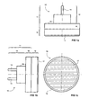
- FIG 1a, b, c show a lamp 10 according to the invention, namely FIG 1a and FIG 1b in side views and 1c in a plan view.
- the lamp 10 comprises a power plug module 11, specifically a power plug adapter 11, and a lighting module 12.
- the power plug adapter 11 includes a power plug 13 and an adapter body 16.
- the power plug 13 has two pins 14.
- the power plug 13 in FIG 1a, b, c is a Schuko plug (earthing contact plug), as is common, for example, in Germany. It corresponds to corresponding Schuko mains outlets, i. is suitable and designed for direct plugging into these sockets.
- the power plug adapter 11 is provided with a housing 15 made of plastic, which encloses both the adapter body 16 and the power plug 13.
- the connection pins 14 of the power plug 13 protrude out of the housing 15.
- the outer shape of the remaining power plug 13 is formed by the housing 15.
- the power plug 13 is integrally formed on the adapter body 16. It could be in power plug 13 and adapter body 16 but also to separate parts that are connected to each other or will act.
- the light module 12 comprises a compact fluorescent lamp and a ballast (both not shown), ie compact fluorescent lamp and Ballast are integrated in the light module 12.
- the light module 12 is provided at its not the power plug adapter 11 facing sides with a protective cover 17 made of plastic. This can be transparent, milky, white or colored or be provided with facets and lets the outgoing of the compact fluorescent lamp light, if necessary light-directing or scattering, step outside.
- the protective cover 17 and the entire light module and also the adapter body 16 of the power plug adapter 11 have in FIG 1a, b, c a circular cross-sectional shape, wherein the circle radius is substantially identical. It can for example be about 75 mm. Alternatively, any other shapes are possible, for example, an angular or oval cross-section.
- FIGS. 2a and 2b show different views of the light module 12 of the lamp 10 from FIG. 1a, b, c, FIGS. 2a and 2b in a side view, FIG. 2c in a bottom view and FIG. 2d in a plan view.
- the protective cover 17 can be seen.
- the lighting module 12 has a circular elevation 18 in which the ballast (not shown) is accommodated.
- the compact fluorescent lamp (not shown) is housed inside the protective cover 17.
- the underside 19 including the elevation 18 is covered by a plastic housing part 20.
- the bayonet base 21 has a circular cross-section. At its free end, the bayonet base 21 are provided with a widening 22.
- the function of the bayonet base 21 results from the following description of the power plug module 11 with reference to FIGS. 3a, b, c, d.
- the bayonet base (base part) may be formed, for example, as a so-called GX53 bayonet base according to the industry standard IEC 7004-142-1 and with a GX53 bayonet mount (bracket) according to the industry standard IEC 7005-142-1 corresponding.
- the light module 12 can be a standard module, as already used in other applications.
- modules which are suitable for installation in furniture and are mounted there on suitably designed sockets may be considered.
- the advantage of the invention in this case is that these modules can now be connected via the power plug adapter 11 directly to a power outlet and thus can be used as a general lighting or as night and / or orientation light. A separate electrical installation of the sockets is then no longer required for these modules. Rather, the lighting modules 12 can be plugged via the power plug adapter 11 in a simple way in any available socket.
- a compact fluorescent lamp i. as a tube, for example, comes a meandering so-called T2 fluorescent lamp into consideration. This has a high efficiency. When using these lamps, a luminous flux of 220 lumens is achievable, the luminous efficacy is high and is 30 lumens / W. The average life of these lamps is 6,000 hours.
- another light source could also be provided in the lighting module, for example a printed circuit board equipped with a plurality of light-emitting diodes.
- the board could be equipped with white light emitting diodes or colored light emitting diodes, in particular red, blue, green LEDs.
- lighting modules could be provided with different light outputs. It could be arranged on a board and light emitting diodes of different colors or different light output and in particular be separately controlled to achieve certain lighting effects.
- FIG. 3a, b, c, d show different views of the power plug adapter 11 of the lamp 10 from FIG. 1a, b, c, FIGS. 3a and 3b in a side view, FIG. 3c in a bottom view and FIG. 3d in a plan view.
- Power plug 13 and adapter body 16 are surrounded by the common housing 15.
- FIG. 3c the design of the mains plug 13 can be clearly seen as a Schuko plug.
- FIG. 3d shows the plan view of a top side 23 of the network adapter 11 facing the lighting module 12 in the assembled lamp 10.
- the top side 23 is also covered by the housing 15.
- the top 23 has a recess 24 which is intended to receive the projection 18 of the light module 12 during assembly of the lamp 10, i. the dimensions of recess 24 and elevation 18 are matched.
- FIG. 3d shows two bayonet mountings 25. These each comprise an opening 26 (also: opening) of the housing 15 on the upper side 23 of the power plug adapter 11.
- the openings 26 have a narrow region 27 and an insertion region 28 which is widened in relation to the narrow region 27.
- the bayonet mountings 25 correspond to the bayonet bases 21 of the lighting module 12, in particular the dimensions of bayonet mountings 25 and bayonet sockets 21 are matched to one another.
- connection between the light module 12 and the power plug adapter 11 is produced by first inserting the bayonet base 21 with its widening 22 into the plug-in regions 28 of the bayonet mountings 25. Subsequently, a rotational movement follows such that the widenings 22 of the bayonet base 21 are respectively arranged below the narrow regions 27 of the bayonet mountings 25, that is, within the housing 15 of the power connector module 11.
- a metal spring (not shown) is arranged in each case. This is intended to lock the widening 22 of the bayonet base 21 in the above-described rotary motion, i. below the narrow portion 27 of the bayonet mount 25. By this locking a defined connection between light module 12 and power plug adapter 11 is made.
- the metal spring also serves to make electrical contact with the metallic bayonet base 21 and thus of the lighting module 12.
- FIGS. 3a, b, c, d show an alternative to that in FIG 3a, b, c, d power plug adapter 11, namely FIG 4a and 4b in a side view, FIG 4c in a bottom view and FIG 4d in a plan view.
- the power plug adapter 11 shown here differs from that shown in FIGS. 3a, b, c, d only in the specific embodiment of the power plug 13.
- the power plug 13 in FIG 4a, b, c, d is a so-called Euro plug. This type of plug is common in Germany, for example. It corresponds with corresponding Euro sockets, but can also be plugged into Schuko sockets.
- the power plug adapter 11 is provided with a housing 15 made of plastic, which encloses both an adapter body 16 and the power plug 13. Again, the outer shape of the power plug 13 is formed by the housing 15, the pins 14 of the power plug 13 protrude from the housing 15 out.
- the power plug 13 is integrally formed on the adapter body 16.
Landscapes
- Engineering & Computer Science (AREA)
- Architecture (AREA)
- General Engineering & Computer Science (AREA)
- Arrangement Of Elements, Cooling, Sealing, Or The Like Of Lighting Devices (AREA)
- Connecting Device With Holders (AREA)
- Details Of Connecting Devices For Male And Female Coupling (AREA)
- Fastening Of Light Sources Or Lamp Holders (AREA)
Abstract
Description
Die Erfindung betrifft eine Lampe, insbesondere für Allgemeinbeleuchtung, die ausgebildet und bestimmt ist für Netz-Steckdosen, insbesondere Wandsteckdosen. Weiter betrifft die Erfindung einen Netzsteckeradapter für ein Leuchtmodul, wobei Netzsteckeradapter und Leuchtmodul eine derartige Lampe bilden.The invention relates to a lamp, in particular for general lighting, which is designed and intended for mains sockets, in particular wall sockets. Furthermore, the invention relates to a power plug adapter for a light module, wherein power plug adapter and light module form such a lamp.
Netzsteckerlampen sind in vielfältigen Ausführungen bekannt z. B. als Nacht- und/oder Orientierungslichter. Sie sind üblicherweise mit einer Glüh- oder Glimmlampe oder einer Leuchtdiode als Leuchtmittel ausgestattet. Bekannt sind sowohl batteriebetriebene als auch an das Stromnetz anzuschließende Ausführungsformen. Die netzgebundenen Varianten weisen einen Netzstecker für den Anschluss an eine Steckdose auf. Dabei ist der Netzstecker in der Regel an ein Nachtlichtgehäuse angeformt.Power plug lamps are known in many designs for. B. as night and / or orientation lights. They are usually equipped with an incandescent or glow lamp or a light emitting diode as a light source. Are known both battery-powered and to be connected to the power grid embodiments. The mains-connected variants have a mains plug for connection to a socket. The power plug is usually formed on a night light housing.
Beispielhaft sein auf die aus DE 78 30 032 U1, DE 44 13 504 A1, DE 203 11 185 U1, DE 102 03 925 A1 bekannten Nacht- und/oder Orientierungslichter verwiesen.For example, refer to the known from DE 78 30 032 U1, DE 44 13 504 A1, DE 203 11 185 U1, DE 102 03 925 A1 night and / or orientation lights.
Ferner ist aus DE 100 54 212 A1 ein Nachtlicht für Netz-Steckdosen bekannt, das ein Leuchtmittel mit einer Vorschaltung aufweist, die zwischen Netzstecker und Leuchtmittel geschaltet ist. Eine Vorschaltung ist immer dann erforderlich, wenn ein Leuchtmittel nicht direkt an die Netzspannung angeschlossen werden kann, beispielsweise ein Glimmlampe oder eine Leuchtdiode.Furthermore, DE 100 54 212 A1 discloses a night light for power sockets, which has a lighting means with a pre-circuit, which is connected between the mains plug and the lighting means. A pre-circuit is always required when a lamp can not be connected directly to the mains voltage, such as a glow lamp or a light emitting diode.
Als Leuchtmittel bekannt sind Kompaktleuchtstofflampen. Die Lichterzeugung basiert bei diesen Kompaktleuchtstofflampen auf dem gleichen Prinzip wie bei herkömmlichen Leuchtstofflampen, d.h. es handelt sich um Niederdruck-Entladungslampen. Durch eine elektrische Entladung zwischen zwei Polen in einem evakuierten Glasrohr wird UV-Strahlung erzeugt, die von Leuchtstoffen auf der Innenseite des Glasrohres in sichtbares Licht umgewandelt wird. Zum Start und Betrieb brauchen Leuchtstofflampen ein Vorschaltgerät. Bei Kompaktleuchtstofflampen ist das Glasrohr gebogen, so dass insgesamt ein sehr kompakter Leuchtkörper vorliegt. Ferner ist bei Kompaktleuchtstofflampen das Vorschaltgerät üblicherweise in die Lampe integriert. Kompaktleuchtstofflampen sind auch als Energiesparlampen bekannt. Sie weisen in der Regel die klassischen Schraubsockel E 14 oder E 27 auf und können somit einfach in vorhandene Glühlampenleuchten eingeschraubt und dort entsprechend betrieben werden. Beispielhaft sei auf EP 0 601 893 B1 verwiesen. Kompaktleuchtstofflampen sind langlebige, energiesparende Lampen.As light bulbs are known compact fluorescent lamps. The light generation based on these compact fluorescent lamps on the same principle as in conventional fluorescent lamps, ie it is low-pressure discharge lamps. By an electrical discharge between two poles in an evacuated glass tube UV radiation is generated, which is converted by phosphors on the inside of the glass tube into visible light. To start and operate fluorescent lamps need a ballast. In compact fluorescent lamps, the glass tube is bent, so that overall there is a very compact luminous body. Furthermore, in compact fluorescent lamps, the ballast is usually integrated in the lamp. Compact fluorescent lamps are also known as energy-saving lamps. They usually have the classic
Es ist Aufgabe der Erfindung, eine neue Lampe (Leuchte), die für die Verwendung in Netzsteckdosen ausgebildet ist, anzugeben.It is an object of the invention to provide a new lamp (light), which is designed for use in power sockets.
Diese Aufgabe wird gemäß der Erfindung durch eine Lampe mit den Merkmalen des Patentanspruchs 1 und durch einen Netzsteckeradapter mit den Merkmalen des Patentanspruchs 10 gelöst. Vorteilhafte Ausgestaltungen und Weiterbildungen sind in den von Anspruch 1 bzw. Anspruch 10 abhängigen Ansprüchen angegeben.This object is achieved according to the invention by a lamp having the features of patent claim 1 and by a power plug adapter having the features of
Die Erfindung sieht gemäß Anspruch 1 eine Lampe (oder: Leuchte) vor, insbesondere eine Lampe für Allgemeinbeleuchtung, die ausgebildet und bestimmt ist für Netz-Steckdosen, insbesondere Wandsteckdosen, und die umfasst
- a) ein Netzsteckermodul, insbesondere einen Netzsteckeradapter, mit einem Netzstecker und
- b) ein Leuchtmodul mit einer Kompaktleuchtstofflampe,
- c) wobei Netzsteckermodul und Leuchtmodul baulich direkt miteinander verbunden oder verbindbar sind.
- a) a power plug module, in particular a power plug adapter, with a power plug and
- b) a light module with a compact fluorescent lamp,
- c) wherein the power plug module and the light module are structurally directly connected or connectable.
Die Vorteile der Erfindung liegen unter anderem darin, dass die an sich bereits vorteilhaften Kompaktleuchtstofflampen nunmehr auch für die Verwendung direkt an Steckdosen einsetzbar sind. Dadurch werden die Vorteile der Kompaktleuchtstofflampen, beispielsweise lange Lebensdauer, wenig Energieverbrauch und geringe Temperaturentwicklung, für diese Anwendungen nutzbar gemacht. Eine spezielle Kompaktleuchtstofflampe dieser Art wird durch die Lampe MICRO-LYNX der Firma SLI Lichtsysteme gebildet, die als Einbaulampe in vormontierten Fassungen kommerziell erhältlich ist.The advantages of the invention include the fact that the already advantageous compact fluorescent lamps are now also suitable for use directly on sockets. This will be the benefits the compact fluorescent lamps, such as long life, low energy consumption and low temperature development, made available for these applications. A special compact fluorescent lamp of this type is formed by the lamp MICRO-LYNX from SLI Lichtsysteme, which is commercially available as a built-in lamp in pre-assembled versions.
Die Kompaktleuchtstofflampe benötigt ein Vorschaltgerät. Dieses Vorschaltgerät kann sowohl im Leuchtmodul als auch im Netzsteckermodul angeordnet sein.The compact fluorescent lamp requires a ballast. This ballast can be arranged both in the light module and in the power plug module.
Die Netzsteckdose kann beispielsweise eine Schutzkontakt(Schuko)-Steckdose oder eine Eurosteckdose sein. Bei dem Netzstecker des Netzsteckermoduls handelt es sich dementsprechend dann um einen Schutzkontakt(Schuko)- oder um einen Eurostecker. Derartige Steckdosensysteme sind beispielsweise in Deutschland verbreitet. Die Lampe bzw. das Netzsteckermodul der Lampe kann jedoch auch passend für jedes andere Steckdosen-System ausgebildet sein, d.h. auch für in Südeuropa, Großbritannien, den USA, Asien und/oder Japan gebräuchliche elektrische Netzsteckdosen-Systeme.The power socket can be, for example, a protective contact (Schuko) socket or a Euro socket. The mains plug of the mains plug module is accordingly a protective contact (Schuko) - or a Euro plug. Such socket systems are common, for example, in Germany. However, the lamp or power plug module of the lamp may also be suitably configured for any other socket system, i. Also for in southern Europe, the United Kingdom, the United States, Asia and / or Japan customary electrical power socket systems.
Vorzugsweise weist das Netzsteckermodul ein Gehäuse auf, an das der Netzstecker angeformt ist.Preferably, the power plug module has a housing to which the power plug is molded.
Eine bevorzugte und zweckmäßige Weiterbildung der Lampe sieht vor, dass die Verbindung zwischen Leuchtmodul und Netzsteckermodul eine reversible mechanische Verbindung ist. Das Leuchtmodul ist somit reversibel mechanisch mit dem Netzsteckermodul verbunden oder verbindbar. Vorzugsweise stellt die reversible mechanische Verbindung gleichzeitig eine elektrische Verbindung zwischen Leuchtmodul und Netzsteckermodul her, d.h. verwirklicht den elektrischen Anschluss der Kompaktleuchtstofflampe.A preferred and expedient development of the lamp provides that the connection between the light module and the power plug module is a reversible mechanical connection. The light module is thus reversibly mechanically connected to the power plug module or connectable. Preferably, the reversible mechanical connection simultaneously establishes an electrical connection between the light module and the power plug module, i. realizes the electrical connection of the compact fluorescent lamp.
Für die Verbindung zwischen Leuchtmodul und Netzsteckermodul sind verschiedenste Verbindungen möglich. Besonders vorteilhaft ist jedoch, wenn die Verbindung zwischen Leuchtmodul und Netzsteckermodul eine oder mehrere, insbesondere zwei, Bajonettverbindungen (oder: Bajonettverschlüsse), insbesondere jeweils umfassend einen Bajonettsockel oder Bajonettstift, vorzugsweise aus Metall, und eine Bajonettfassung zur Aufnahme des Bajonettsockels bzw. Bajonettstiftes, umfasst. Bevorzugt ist dabei, wenn die Verbindung zwischen Leuchtmodul und Netzsteckermodul ausschließlich über die Bajonettverbindungen erfolgt.Various connections are possible for the connection between the light module and the mains plug module. However, it is particularly advantageous if the connection between light module and power plug module one or more, in particular two, bayonet (or: bayonet), in particular each comprising a bayonet socket or bayonet pin, preferably of metal, and a bayonet mount for receiving the bayonet socket or bayonet pin. It is preferred in this case if the connection between the light module and the power plug module takes place exclusively via the bayonet connections.
Das Leuchtmodul ist somit vom Netzsteckermodul abnehmbar. Der Vorteil dieser Weiterbildung liegt unter anderem in der einfachen Austauschbarkeit des Leuchtmoduls. Das Netzsteckermodul kann auch nach Ende der Lebensdauer des Leuchtmoduls weitergenutzt werden, es muss nur ein neues Leuchtmodul angebracht werden.The light module is thus removable from the power plug module. The advantage of this development is, inter alia, the simple interchangeability of the light module. The power plug module can continue to be used after the end of the life of the light module, it must be attached only a new light module.
Bei einer Bajonettverbindung bzw. einem Bajonettverschluss erfolgt die Verbindung der Teile über eine Steck-Dreh-Bewegung. Hierzu werden die beiden zu verbindenden Teile zunächst ineinandergesetzt, üblicherweise dadurch, dass der Bajonettsockel bzw. Bajonettstift in eine Öffnung der Bajonettfassung eingesetzt wird. Anschließend werden die Teile durch eine Drehbewegung relativ zueinander gegeneinander gedrückt, üblicherweise indem bei der Drehbewegung eine Verbreiterung des Bajonettsockels bzw. - stifts über eine Auflagefläche der Bajonettfassung geschoben wird und dadurch der Bajonettsockel bzw. -stift nicht mehr aus der Öffnung der Bajonettfassung herausgezogen werden kann. Ein Lösen der Teile erfordert daher zunächst erneut eine Drehbewegung, erst anschließend können die Teile durch Herausziehen des Bajonettsockels bzw. -stifts aus der Öffnung getrennt werden. Der Drehwinkel ist beim Öffnen und Schließen vom Betrag her identisch, nur die Drehrichtung ist umgekehrt. Der Drehwinkel kann verhältnismäßig klein sein und beispielsweise zwischen 10° und 20°, insbesondere 14° 30' und 15° 30' liegen. Die Bajonettverbindung ist eine leicht zu handhabende, insbesondere leicht herstellbare und wieder lösbare Verbindung.In a bayonet connection or a bayonet connection, the connection of the parts via a plug-in rotary movement. For this purpose, the two parts to be joined are initially interlocked, usually in that the bayonet socket or bayonet pin is inserted into an opening of the bayonet mount. Subsequently, the parts are pressed against each other by a rotational movement relative to one another, usually by a widening of the bayonet socket or - pin is pushed over a bearing surface of the bayonet mount during rotation and thereby the bayonet base or pin can not be pulled out of the opening of the bayonet mount , Therefore, a release of the parts requires first again a rotary motion, only then the parts can be separated by pulling the bayonet base or pin out of the opening. The angle of rotation is identical when opening and closing, only the direction of rotation is reversed. The angle of rotation can be relatively small and, for example, between 10 ° and 20 °, in particular 14 ° 30 'and 15 ° 30' lie. The bayonet connection is an easy-to-use, especially easy to produce and detachable connection.
Bevorzugt sind bei der Lampe die Bajonettsockel bzw. -stifte am Leuchtmodul und die Bajonettfassungen mit den Öffnungen am Netzsteckermodul vorgesehen. Aber auch eine umgekehrte Ausbildung oder eine Mischform ist möglich. Sollte die Bajonettverbindung jedoch auch zur Herstellung einer elektrischen Verbindung zwischen Leuchtmodul und Netzsteckermodul verwendet werden, so ist aus Sicherheitsgründen die erstgenannte Ausbildung der Bajonettsockel am Leuchtmodul vorzuziehen (weiter Erläuterungen untenstehend). Zweckmäßig sind in diesem Fall zwei Bajonettsockel, die mit zwei Bajonettfassungen korrespondieren.The bayonet base or pins on the light module and the bayonet mountings with the openings on the power plug module are preferably provided in the lamp. But also a reverse education or a mixed form is possible. However, should the bayonet connection also be used to make an electrical connection between the light module and the power plug module, then for safety reasons, the former training the bayonet socket on the light module preferable (further explanations below). It is expedient in this case two bayonet sockets, which correspond to two bayonet mountings.
Gemäß einer zweckmäßigen Weiterbildung weisen die Bajonettverbindungen eine reversible Verrastung auf. Diese Verrastung kann beispielsweise durch mindestens eine in der Bajonettfassung vorgesehene Feder, vorzugsweise Metallfeder, erfolgen. Beim Schließen der Bajonettverbindung, und zwar beim Ausführen der Drehbewegung, muss zunächst ein Widerstand, der von der Feder ausgeht, überwunden werden, ehe die Bajonettverbindung in den geschlossenen Zustand übergeht (verrastet). Beim Lösen der Bajonettverbindung muss ebenfalls zunächst ein Widerstand, der wiederum von der Feder ausgeht, überwunden werden, und zwar auch bei der Drehbewegung, ehe das Leuchtmodul vom Netzsteckermodul abnehmbar ist.According to an expedient development, the bayonet connections have a reversible latching. This locking can be done for example by at least one provided in the bayonet mount spring, preferably metal spring. When closing the bayonet connection, namely while performing the rotational movement, a resistance that originates from the spring, must first be overcome before the bayonet connection in the closed state transitions (locked). When releasing the bayonet connection, a resistance, which in turn starts from the spring, must also be overcome first, even during the rotational movement, before the light module can be removed from the power plug module.
Die Kompaktleuchtstofflampe muss - über ein Vorschaltgerät - an die Netzspannung angeschlossen werden. Hierzu ist eine elektrische Verbindung zwischen Leuchtmodul und Netzsteckermodul erforderlich. Verschiedenste Varianten sind hierfür denkbar. Gemäß einer besonders bevorzugten und vorteilhaften Ausführungsform der Lampe ist vorgesehen, dass die elektrische Verbindung zwischen Netzsteckermodul und Leuchtmodul über die Bajonettverbindungen hergestellt oder herstellbar ist, insbesondere über metallische Bajonettsockel oder Bajonettstifte, die bei geschlossener Bajonettverbindung jeweils eine oder mehrere Metallfedern in der Bajonettfassung kontaktieren. Die Metallfedern sind wiederum über den Netzstecker mit der Netzspannung verbunden oder verbindbar. Beim Schließen der Bajonettverbindung wird somit gleichzeitig die mechanische und die elektrische Verbindung zwischen Netzsteckermodul und Leuchtmodul hergestellt.The compact fluorescent lamp must be connected to the mains voltage via a ballast. For this purpose, an electrical connection between the light module and power plug module is required. Various variants are conceivable for this. According to a particularly preferred and advantageous embodiment of the lamp, it is provided that the electrical connection between the power plug module and the light module is produced or producible via the bayonet connections, in particular via metallic bayonet sockets or bayonet pins, which each contact one or more metal springs in the bayonet mount when the bayonet connection is closed. The metal springs are in turn connected via the mains plug with the mains voltage or connectable. When closing the bayonet connection thus simultaneously the mechanical and the electrical connection between the power plug module and the light module is made.
Zweckmäßig ist dabei das Vorsehen von zwei elektrischen Verbindungen über zwei Bajonettverbindungen. Sinnvoll ist ferner, wenn die Bajonettfassungen am Netzsteckermodul und die Bajonettsockel bzw. -stifte am Leuchtmodul vorgesehen sind, da auf diese Weise die gegebenenfalls mit der Netzspannung verbundenen Metallfedern innerhalb des Netzsteckermoduls untergebracht sein können und damit ein versehentliches Berühren der stromführenden Teile durch Personen auch bei abgenommenem Leuchtmodul weitestgehend verhindert ist.It is expedient to provide two electrical connections via two bayonet connections. It is also useful if the bayonet sockets on the power plug module and the bayonet base or pins are provided on the light module, as may be accommodated in this way, the metal springs connected to the mains voltage within the power plug module and thus accidental touching the current carrying parts is largely prevented by persons even with removed light module.
Gemäß einer vorteilhaften Ausführungsform der Lampe sind verschiedene Leuchtmodule mit dem Netzsteckermodul verbindbar. Die Leuchtmodule können sich dabei beispielsweise in ihrer Farbe und/oder ihrer Leuchtstärke und/oder ihrer Formgebung unterscheiden.According to an advantageous embodiment of the lamp, different lighting modules can be connected to the mains plug module. The lighting modules may differ, for example, in their color and / or their luminosity and / or their shape.
Der Vorteil dieser Ausführungsform liegt unter anderem darin, dass verschiedene Arten von Leuchtmodulen entsprechend den Wünschen des Nutzers durch einfachen Austausch verwendbar sind. Hierfür kann dem Nutzer ein entsprechender Leuchtmodul-Satz angeboten werden. Das Angebot kann beispielsweise Leuchtmodule verschiedener Farbe umfassen, beispielsweise neben weiß leuchtenden Modulen auch rot, grün oder blau leuchtende Module. Ferne können Leuchtmodule mit verschiedenen Leuchtstärken auswählbar sein. Auch können verschiedene Designs bereitgestellt werden, d.h. Leuchtmodule mit unterschiedlicher Formgebung, beispielsweise mit rundem, eckigem oder ovalem Querschnitt oder mit einer flächigen oder strukturierte Front und/oder mit aufgedruckten Motiven.The advantage of this embodiment is, inter alia, that different types of lighting modules can be used according to the wishes of the user by simple replacement. For this purpose, the user can be offered a corresponding lighting module set. The offer may include, for example, light modules of different colors, for example, in addition to white light modules also red, green or blue shining modules. Remote lighting modules with different luminous intensities can be selected. Also, various designs can be provided, i. Light modules with different shapes, for example with a round, square or oval cross section or with a flat or structured front and / or printed motifs.
Vorzugsweise weist das Leuchtmodul ein Gehäuse auf. Insbesondere wird das Leuchtmittel abgedeckt von einer Schutzabdeckung, insbesondere einer lichtlenkenden und/oder lichtstreuenden Schutzabdeckung.Preferably, the lighting module has a housing. In particular, the lighting means is covered by a protective cover, in particular a light-directing and / or light-scattering protective cover.
Die Lampen gemäß der Erfindung können aufgrund ihrer langen Lebensdauer und Energiespareigenschaft für den Dauerbetrieb ausgelegt sein. Es ist aber ebenso möglich, einen Ein-Aus-Schalter vorzusehen, beispielsweise einen mechanischen, von einem Nutzer zu betätigenden Schalter und/oder einen auf Bewegungen reagierenden Schalter, d.h. einen mit einem Bewegungsmelder gekoppelten Schalter, und/oder einen Dämmerungsschalter, d.h. einen mit einem Helligkeitssensor gekoppelten Schalter. Die Schalter können am Netzsteckermodul und/oder am Leuchtmodul vorgesehen sein.The lamps according to the invention can be designed for continuous operation due to their long life and energy saving property. However, it is also possible to provide an on-off switch, for example a mechanical, user-operable switch and / or a motion-responsive switch, i. a switch coupled to a motion detector, and / or a twilight switch, i. a switch coupled to a brightness sensor. The switches can be provided on the power plug module and / or on the light module.
Die Erfindung gemäß Anspruch 10 sieht einen Netzsteckeradapter vor, der speziell ausgebildet und bestimmt ist für die Verbindung mit einem Leuchtmodul, das eine Kompaktleuchtstofflampe umfasst. Insbesondere ist dieser Netzsteckeradapter ausgebildet und bestimmt für die Verwendung in einer Lampe gemäß der Erfindung. Der Netzsteckeradapter gemäß der Erfindung umfasst einen Netzstecker und mindestens ein mit dem Leuchtmodul korrespondierendes Verbindungselement.The invention according to
Die Vorteile dieses Netzsteckeradapters ergeben sich aus den vorstehenden Ausführungen.The advantages of this plug adapter arise from the above.
Vorzugsweise ist ein Vorschaltgerät für die Kompaktleuchtstofflampe ebenfalls im Leuchtmodul angeordnet. Das Vorschaltgerät kann alternativ allerdings auch im Netzsteckeradapter untergebracht sein.Preferably, a ballast for the compact fluorescent lamp is also arranged in the light module. The ballast may alternatively be accommodated in the power plug adapter.
Gemäß einer zweckmäßigen Weiterbildung des Netzsteckeradapters sind als Verbindungselement bzw. Verbindungselemente mindestens eine, insbesondere zwei, Bajonettfassungen zur Aufnahme eines oder mehrerer, insbesondere zweier, am Leuchtmodul vorgesehener Bajonettsockel, insbesondere aus Metall, vorgesehen, wobei Bajonettfassung und Bajonettsockel jeweils eine Bajonettverbindung ausbilden.According to an expedient development of the power plug adapter are at least one, in particular two, bayonet mountings for receiving one or more, in particular two, provided on the light module bayonet cap, in particular of metal, provided as a connecting element or connecting elements, wherein bayonet mount and bayonet each form a bayonet connection.
Gemäß einer Weiterbildung ist in der Bajonettfassung oder den Bajonettfassungen jeweils zumindest eine Feder, insbesondere Metallfeder, zur reversiblen Verrastung der Bajonettverbindung und/oder zur Ausbildung eines elektrischen Kontakts zum Leuchtmodul vorgesehen. Die Federn sind im Netzsteckermodul mit Anschlussstiften des Netzsteckers elektrisch verbunden, so dass sie beim Einstecken des Netzsteckermoduls in eine Netzsteckdose mit der Netzspannung verbunden sind - gegebenenfalls nach Schließen eines Schalters. Über die mit den Metallfedern verrastenden Bajonettsockel wird die elektrische Verbindung zwischen Leuchtmodul und Netzspannung und damit zwischen Vorschaltgerät bzw. Kompaktleuchtstofflampe und Netzspannung hergestellt.According to a further development, at least one spring, in particular a metal spring, is provided in the bayonet mount or the bayonet mountings for reversibly latching the bayonet connection and / or for forming an electrical contact with the lighting module. The springs are electrically connected in the power plug module with pins of the power plug, so that they are connected when plugging the power plug into a power outlet with the mains voltage - possibly after closing a switch. The electrical connection between the light module and the mains voltage and thus between ballast or compact fluorescent lamp and mains voltage is established via the bayonet base latching with the metal springs.
Die Erfindung wird nachstehend auch hinsichtlich weiterer Merkmale und Vorteile anhand der Beschreibung von Ausführungsbeispielen und unter Bezugnahme auf die beiliegenden Zeichnungen näher erläutert.The invention will be explained below with regard to further features and advantages with reference to the description of exemplary embodiments and with reference to the accompanying drawings.
Es zeigen
- FIG 1a, b, c
- verschiedene Ansichten einer Lampe gemäß der Erfindung,
- FIG 2a, b, c, d
- verschiedene Ansichten eines Leuchtmoduls der Lampe gemäß FIG 1a, b, c,
- FIG 3a, b, c, d
- verschiedene Ansichten eines Netzsteckermoduls der Lampe gemäß FIG 1a, b, c, und
- FIG 4a, b, c, d
- ein alternatives Netzsteckermodul.
- FIGS. 1a, b, c
- different views of a lamp according to the invention,
- FIGS. 2a, b, c, d
- different views of a light module of the lamp according to FIG 1a, b, c,
- FIGS. 3a, b, c, d
- different views of a power plug module of the lamp according to FIG 1a, b, c, and
- FIGS. 4a, b, c, d
- an alternative power plug module.
Einander entsprechende Teile sind in den Figuren mit den gleichen Bezugszeichen versehen.Corresponding parts are provided in the figures with the same reference numerals.
FIG 1a, b, c zeigen eine Lampe 10 gemäß der Erfindung, und zwar FIG 1a und FIG 1b in Seitenansichten und FIG 1c in einer Draufsicht. Die Lampe 10 umfasst ein Netzsteckermodul 11, und zwar konkret einen Netzsteckeradapter 11, sowie ein Leuchtmodul 12.1a, b, c show a
Der Netzsteckeradapter 11 umfasst einem Netzstecker 13 und einen Adapterkörper 16. Der Netzstecker 13 weist zwei Anschlussstifte 14 auf. Der Netzstecker 13 in FIG 1a, b, c ist ein Schuko-Stecker (Schutzkontakt-Stecker), wie er beispielsweise in Deutschland üblich ist. Er korrespondiert mit entsprechenden Schuko-Netzsteckdosen, d.h. ist geeignet und ausgebildet zum direkten Einstecken in diese Steckdosen. Der Netzsteckeradapter 11 ist mit einem Gehäuse 15 aus Kunststoff versehen, das sowohl den Adapterkörper 16 als auch den Netzstecker 13 umschließt. Die Anschlussstifte 14 des Netzsteckers 13 ragen aus dem Gehäuse 15 heraus. Die Außenform des restliche Netzsteckers 13 ist vom Gehäuse 15 gebildet. Der Netzstecker 13 ist an den Adapterkörper 16 angeformt. Es könnte sich bei Netzstecker 13 und Adapterkörper 16 aber auch um getrennte Teile, die mit einander verbunden sind bzw. werden, handeln.The
Das Leuchtmodul 12 umfasst eine Kompaktleuchtstofflampe und ein Vorschaltgerät (beides nicht dargestellt), d.h. Kompaktleuchtstofflampe und Vorschaltgerät sind in das Leuchtmodul 12 integriert. Das Leuchtmodul 12 wird an seinen nicht dem Netzsteckeradapter 11 zugewandten Seiten mit einer Schutzabdeckung 17 aus Kunststoff versehen. Diese kann transparent, milchig, weiß oder farbig oder mit Facetten versehen sein und lässt das von der Kompaktleuchtstofflampe ausgehende Licht, gegebenenfalls lichtlenkend oder streuend, nach außen treten.The
Die Schutzabdeckung 17 sowie das gesamte Leuchtmodul und auch der Adapterkörper 16 des Netzsteckeradapters 11 weisen in FIG 1a, b, c eine kreisförmige Querschnittsform auf, wobei der Kreisradius im Wesentlichen identisch ist. Er kann beispielsweise bei etwa 75 mm liegen. Alternativ sind beliebige andere Formen möglich, beispielsweise ein eckiger oder ovaler Querschnitt.The
FIG 2a, b, c, d zeigen verschiedene Ansichten des Leuchtmoduls 12 der Lampe 10 aus FIG 1a, b, c, und zwar FIG 2a und FIG 2b in einer Seitenansicht, FIG 2c in einer Unteransicht und FIG 2d in einer Draufsicht. Zu erkennen ist die Schutzabdeckung 17. An einer in der zusammengesetzten Lampe 10 dem Netzsteckermodul 11 zugewandten Unterseite 19 weist das Leuchtmodul 12 eine kreisförmige Erhebung 18 auf, in der das Vorschaltgerät (nicht dargestellt) untergebracht ist. Die Kompaktleuchtstofflampe (nicht dargestellt) ist innerhalb der Schutzabdeckung 17 untergebracht. Die Unterseite 19 einschließlich der Erhebung 18 ist von einem Kunststoffgehäuseteil 20 abgedeckt.2a, b, c, d show different views of the
Aus der Unterseite 19 des Leuchtmoduls 12 ragen zwei metallische Bajonettsockel 21 (auch: Bajonettstifte) heraus. Die Bajonettsockel 21 weisen einen kreisförmigen Querschnitt auf. An ihrem freien Ende sind die Bajonettsockel 21 mit einer Verbreiterung 22 versehen. Die Funktion der Bajonettsockel 21 ergibt sich aus der nachfolgenden Beschreibung des Netzsteckermoduls 11 anhand der FIG 3a, b, c, d. Der Bajonettsockel (Sockelteil) kann beispielsweise als sogenannter GX53 Bajonettsockel nach der Industrienorm IEC 7004-142-1 und mit einer GX53 Bajonettfassung (Halterung) nach der Industrienorm IEC 7005-142-1 korrespondierend ausgebildet sein.From the bottom 19 of the
Bei dem Leuchtmodul 12 kann es sich um ein Standardmodul, wie es bereits in anderen Anwendungen eingesetzt wird, handeln. In Betracht kommen beispielsweise Module, die für den Einbau in Möbel geeignet sind und dort auf geeignet ausgebildeten Fassungen angebracht werden. Der Vorteil der Erfindung liegt in diesem Fall darin, dass diese Module nunmehr über den Netzsteckeradapter 11 direkt an eine Netzsteckdose angeschlossen werden können und damit als Allgemeinbeleuchtung oder als Nacht- und/oder Orientierungslicht verwendbar sind. Eine eigene elektrische Installation der Fassungen ist dann für diese Module nicht mehr erforderlich. Vielmehr können die Leuchtmodule 12 über den Netzsteckeradapter 11 auf einfache Weise in jede zur Verfügung stehende Steckdose eingesteckt werden.The
Als eigentliche Kompaktleuchtstofflampe, d.h. als Röhre, kommt beispielsweise eine mäanderförmige sogenannte T2 Leuchtstofflampe in Betracht. Diese hat einen hohen Wirkungsgrad. Bei Verwendung dieser Lampen ist ein Lichtstrom von 220 Lumen erreichbar, die Lichtausbeute ist hoch und liegt bei 30 Lumen/W. Die mittlere Lebensdauer dieser Lampen liegt bei 6.000 Stunden. Anstelle einer Kompaktleuchtstofflampe könnte im Leuchtmodul auch eine andere Lichtquelle vorgesehen sein, beispielsweise eine mit einer Mehrzahl von Leuchtdioden bestückte Platine. Die Platine könnte mit weißen Leuchtdioden oder farbigen Leuchtdioden, insbesondere roten, blauen, grünen Leuchtdioden bestückt sein. Auch könnten Leuchtmodule mit verschiedenen Lichtleistungen vorgesehen sein. Es könnten auf einer Platine auch Leuchtdioden unterschiedlicher Farbe bzw. unterschiedlicher Lichtleistung angeordnet und insbesondere getrennt ansteuerbar sein, um bestimmte Lichteffekte zu erzielen.As an actual compact fluorescent lamp, i. as a tube, for example, comes a meandering so-called T2 fluorescent lamp into consideration. This has a high efficiency. When using these lamps, a luminous flux of 220 lumens is achievable, the luminous efficacy is high and is 30 lumens / W. The average life of these lamps is 6,000 hours. Instead of a compact fluorescent lamp, another light source could also be provided in the lighting module, for example a printed circuit board equipped with a plurality of light-emitting diodes. The board could be equipped with white light emitting diodes or colored light emitting diodes, in particular red, blue, green LEDs. Also, lighting modules could be provided with different light outputs. It could be arranged on a board and light emitting diodes of different colors or different light output and in particular be separately controlled to achieve certain lighting effects.
FIG 3a, b, c, d zeigen verschiedene Ansichten des Netzsteckeradapters 11 der Lampe 10 aus FIG 1a, b, c, und zwar FIG 3a und FIG 3b in einer Seitenansicht, FIG 3c in einer Unteransicht und FIG 3d in einer Draufsicht. Zu erkennen sind der Netzstecker 13 mit seinen Anschlussstiften 14 sowie der Adapterkörper 16. Netzstecker 13 und Adapterkörper 16 sind von dem gemeinsamen Gehäuse 15 umgeben. In FIG 3c ist deutlich die Ausbildung des Netzsteckers 13 als Schukostecker zu erkennen.3a, b, c, d show different views of the
FIG 3d zeigt die Draufsicht auf eine in der zusammengesetzten Lampe 10 dem Leuchtmodul 12 zugewandte Oberseite 23 des Netzwerkadapters 11. Auch die Oberseite 23 ist vom Gehäuse 15 abgedeckt. Die Oberseite 23 weist eine Vertiefung 24 auf, die zur Aufnahme der Erhebung 18 des Leuchtmoduls 12 beim Zusammenbau der Lampe 10 bestimmt ist, d.h. die Abmessungen von Vertiefung 24 und Erhebung 18 sind aufeinander abgestimmt.FIG. 3d shows the plan view of a
Ferner zeigt FIG 3d zwei Bajonettfassungen 25. Diese umfassen jeweils eine Durchbrechung 26 (auch: Öffnung) des Gehäuses 15 an der Oberseite 23 des Netzsteckeradapters 11. Die Durchbrechungen 26 weisen einen Schmalbereich 27 und einen gegenüber dem Schmalbereich 27 verbreiterten Einsteckbereich 28 auf. Die Bajonettfassungen 25 korrespondieren mit den Bajonettsockeln 21 des Leuchtmoduls 12, insbesondere sind die Abmessungen von Bajonettfassungen 25 und Bajonettsockeln 21 aufeinander abgestimmt.Furthermore, FIG. 3d shows two
Die Verbindung zwischen Leuchtmodul 12 und Netzsteckeradapter 11 wird dadurch hergestellt, dass die Bajonettsockel 21 zunächst mit ihrer Verbreiterung 22 in die Einsteckbereiche 28 der Bajonettfassungen 25 eingesteckt werden. Anschließend folgt eine Drehbewegung derart, dass die Verbreiterungen 22 der Bajonettsockel 21 jeweils unterhalb der Schmalbereiche 27 der Bajonettfassungen 25 angeordnet werden, das heißt innerhalb des Gehäuses 15 des Netzsteckermoduls 11.The connection between the
Innerhalb des Gehäuses 15, unterhalb der Durchbrechungen 26 der Bajonettfassungen 25, ist jeweils eine Metallfeder (nicht dargestellt) angeordnet. Diese ist bestimmt zur Verrastung der Verbreiterung 22 des Bajonettsockels 21 bei der oben beschriebenen Drehbewegung, d.h. unterhalb des Schmalbereichs 27 der Bajonettfassung 25. Durch diese Verrastung wird eine definierte Verbindung zwischen Leuchtmodul 12 und Netzsteckeradapter 11 hergestellt. Die Metallfeder dient ferner der elektrischen Kontaktierung der metallischen Bajonettsockel 21 und damit des Leuchtmoduls 12.Within the
FIG 4a, b, c, d zeigen einen zu dem in FIG 3a, b, c, d alternativen Netzsteckeradapter 11, und zwar FIG 4a und FIG 4b in einer Seitenansicht, FIG 4c in einer Unteransicht und FIG 4d in einer Draufsicht. Der hier dargestellte Netzsteckeradapter 11 unterscheidet sich von dem im FIG 3a, b, c, d dargestellten lediglich in der konkreten Ausgestaltung des Netzsteckers 13. Der Netzstecker 13 in FIG 4a, b, c, d ist ein sogenannter Euro-Stecker. Auch diese Steckerart ist beispielsweise in Deutschland üblich. Er korrespondiert mit entsprechenden Euro-Steckdosen, kann aber auch in Schuko-Steckdosen eingesteckt werden. Auch hier ist der Netzsteckeradapter 11 mit einem Gehäuse 15 aus Kunststoff versehen, das sowohl einen Adapterkörper 16 als auch den Netzstecker 13 umschließt. Auch hier ist die Außenform des Netzsteckers 13 vom Gehäuse 15 gebildet, die Anschlussstifte 14 des Netzsteckers 13 ragen aus dem Gehäuse 15 heraus. Der Netzstecker 13 ist an den Adapterkörper 16 angeformt.4a, b, c, d show an alternative to that in FIG 3a, b, c, d
- 1010
- Lampelamp
- 1111
- Netzsteckermodul, NetzsteckeradapterPower plug module, power plug adapter
- 1212
- Leuchtmodullight module
- 1313
- Netzsteckerpower plug
- 1414
- Anschlussstiftepins
- 1515
- Gehäuse des NetzsteckeradaptersHousing of the power plug adapter
- 1616
- Adapterkörperadapter body
- 1717
- Schutzabdeckungprotective cover
- 1818
- Erhebungsurvey
- 1919
- Unterseite des LeuchtmodulsBottom of the light module
- 2020
- Gehäuseteil des LeuchtmodulsHousing part of the light module
- 2121
- Bajonettsockelbayonet base
- 2222
-
Verbreiterung des Bajonettsockels 21Widening of the
bayonet socket 21 - 2323
-
Oberseite des Netzsteckeradapters 11Top of the
power plug adapter 11 - 2424
- Vertiefungdeepening
- 2525
- Bajonettfassungenbayonet sockets
- 2626
- Durchbrechungen des Gehäuses 15Openings of the housing 15th
- 2727
- Schmalbereichnarrow range
- 2828
- Einsteckbereichinsertion
Claims (12)
Priority Applications (4)
| Application Number | Priority Date | Filing Date | Title |
|---|---|---|---|
| EP04024832A EP1650488B1 (en) | 2004-10-19 | 2004-10-19 | Lamp, especially for general illumination, designed for mains current. |
| ES04024832T ES2285332T3 (en) | 2004-10-19 | 2004-10-19 | LAMP, IN SPECIAL FOR GENERAL LIGHTING, CONFIGURED AND DETERMINED FOR FEMALE NETWORK PLUGS. |
| DE502004003226T DE502004003226D1 (en) | 2004-10-19 | 2004-10-19 | Lamp, in particular for general lighting, designed and intended for mains sockets |
| AT04024832T ATE356957T1 (en) | 2004-10-19 | 2004-10-19 | LAMP, ESPECIALLY FOR GENERAL LIGHTING, DESIGNED AND DESIGNED FOR MAINS SOCKETS |
Applications Claiming Priority (1)
| Application Number | Priority Date | Filing Date | Title |
|---|---|---|---|
| EP04024832A EP1650488B1 (en) | 2004-10-19 | 2004-10-19 | Lamp, especially for general illumination, designed for mains current. |
Publications (2)
| Publication Number | Publication Date |
|---|---|
| EP1650488A1 true EP1650488A1 (en) | 2006-04-26 |
| EP1650488B1 EP1650488B1 (en) | 2007-03-14 |
Family
ID=34927027
Family Applications (1)
| Application Number | Title | Priority Date | Filing Date |
|---|---|---|---|
| EP04024832A Expired - Lifetime EP1650488B1 (en) | 2004-10-19 | 2004-10-19 | Lamp, especially for general illumination, designed for mains current. |
Country Status (4)
| Country | Link |
|---|---|
| EP (1) | EP1650488B1 (en) |
| AT (1) | ATE356957T1 (en) |
| DE (1) | DE502004003226D1 (en) |
| ES (1) | ES2285332T3 (en) |
Citations (10)
| Publication number | Priority date | Publication date | Assignee | Title |
|---|---|---|---|---|
| US1989752A (en) * | 1931-11-02 | 1935-02-05 | Herbert H Ice | Uni-plural plugging in and switch device |
| DE7830032U1 (en) | 1978-10-09 | 1979-02-08 | Gluehma Gmbh & Co, 3400 Goettingen | NIGHT LIGHT DOUBLE PLUG |
| DE4030154A1 (en) * | 1990-09-24 | 1991-05-16 | Gerhard Neumann | Multi-pole plug connector for heavy current - has plug box of contact socket retaining housing part, and pivotal top housing part |
| US5420764A (en) * | 1993-07-16 | 1995-05-30 | American Power Products, Inc. | Socket/tab supported light fixture |
| DE4413504A1 (en) | 1994-04-19 | 1995-10-26 | Sonlux Licht Und Elektroinstal | House number or signboard illumination and locational guidance light |
| EP0892210A2 (en) * | 1997-07-19 | 1999-01-20 | Frédéric Baillod | Articulated electric compact lamp |
| EP0601893B1 (en) | 1992-12-11 | 1999-06-09 | Flowil International Lighting (Holding) B.V. | Fluorescent lamp |
| DE10054212A1 (en) | 2000-11-02 | 2002-05-08 | Hans Dokoupil | Night-light for mains sockets, especially wall sockets has ballast with current-limiting condenser, voltage-stable with small dimensions and at least one lamp element as lighting device |
| DE10203925A1 (en) | 2002-01-31 | 2003-08-14 | Reinhard Napierski | Electric night light for operating in a bedroom has a casing, a rotary cover to lock in the casing with a hook, a lamp and a musical clock. |
| DE20311185U1 (en) | 2003-07-21 | 2003-10-23 | Heinrich Kopp Ag, 63796 Kahl | Night light for dark rooms has recess in a housing containing a light and a plug for additional connections |
-
2004
- 2004-10-19 EP EP04024832A patent/EP1650488B1/en not_active Expired - Lifetime
- 2004-10-19 AT AT04024832T patent/ATE356957T1/en not_active IP Right Cessation
- 2004-10-19 ES ES04024832T patent/ES2285332T3/en not_active Expired - Lifetime
- 2004-10-19 DE DE502004003226T patent/DE502004003226D1/en not_active Expired - Lifetime
Patent Citations (10)
| Publication number | Priority date | Publication date | Assignee | Title |
|---|---|---|---|---|
| US1989752A (en) * | 1931-11-02 | 1935-02-05 | Herbert H Ice | Uni-plural plugging in and switch device |
| DE7830032U1 (en) | 1978-10-09 | 1979-02-08 | Gluehma Gmbh & Co, 3400 Goettingen | NIGHT LIGHT DOUBLE PLUG |
| DE4030154A1 (en) * | 1990-09-24 | 1991-05-16 | Gerhard Neumann | Multi-pole plug connector for heavy current - has plug box of contact socket retaining housing part, and pivotal top housing part |
| EP0601893B1 (en) | 1992-12-11 | 1999-06-09 | Flowil International Lighting (Holding) B.V. | Fluorescent lamp |
| US5420764A (en) * | 1993-07-16 | 1995-05-30 | American Power Products, Inc. | Socket/tab supported light fixture |
| DE4413504A1 (en) | 1994-04-19 | 1995-10-26 | Sonlux Licht Und Elektroinstal | House number or signboard illumination and locational guidance light |
| EP0892210A2 (en) * | 1997-07-19 | 1999-01-20 | Frédéric Baillod | Articulated electric compact lamp |
| DE10054212A1 (en) | 2000-11-02 | 2002-05-08 | Hans Dokoupil | Night-light for mains sockets, especially wall sockets has ballast with current-limiting condenser, voltage-stable with small dimensions and at least one lamp element as lighting device |
| DE10203925A1 (en) | 2002-01-31 | 2003-08-14 | Reinhard Napierski | Electric night light for operating in a bedroom has a casing, a rotary cover to lock in the casing with a hook, a lamp and a musical clock. |
| DE20311185U1 (en) | 2003-07-21 | 2003-10-23 | Heinrich Kopp Ag, 63796 Kahl | Night light for dark rooms has recess in a housing containing a light and a plug for additional connections |
Also Published As
| Publication number | Publication date |
|---|---|
| EP1650488B1 (en) | 2007-03-14 |
| DE502004003226D1 (en) | 2007-04-26 |
| ES2285332T3 (en) | 2007-11-16 |
| ATE356957T1 (en) | 2007-04-15 |
Similar Documents
| Publication | Publication Date | Title |
|---|---|---|
| DE102005060971B4 (en) | High performance LED color light with infrared remote control function | |
| EP1845588B1 (en) | Electrical installation unit and associated central cover | |
| DE19607208C2 (en) | Fluorescent lamp with replaceable light part | |
| WO2001060119A2 (en) | Lighting body | |
| DE102010031587A1 (en) | Two-piece top-mount PCB edge connector and component assembly | |
| DE202006009693U1 (en) | Light-emitting diode lamp adapter kit, includes adapter cable with range of lamp bases and is used to replace incandescent bulb of vehicle interior lamp | |
| DE102009042615B4 (en) | Connection element for the electrical connection of an LED | |
| DE202005020471U1 (en) | Light emitting diode lamp, has two end caps with set of assembly pins that are combined with connector of conventional holder for fluorescent lamp to fasten light emitting diode lamp tube to holder | |
| DE8431386U1 (en) | Adapter for a single-ended low-pressure discharge lamp | |
| DE102009009520A1 (en) | Plug-in module for a modular light source, light module for the light source as well as a modular light source | |
| EP1650488B1 (en) | Lamp, especially for general illumination, designed for mains current. | |
| WO2017140885A1 (en) | Lamp | |
| DE202004016241U1 (en) | Lamp, especially for general lighting and mains plug sockets has mains plug module and light module, preferably with compact fluorescent lamp, that are directly structurally connected/can be connected | |
| DE29820247U1 (en) | Illuminant | |
| EP1963734B1 (en) | Built-in illuminator as an interior and exterior light | |
| DE60033263T2 (en) | Carrier for autonomous emergency block and autonomous block with such a carrier | |
| DE102016107147B4 (en) | Switch cabinet light with adjustable illuminant board | |
| DE29500790U1 (en) | Energy saving lamp | |
| DE102008017265A1 (en) | Lamp e.g. floor lamp and table lamp, has body forming lamp housing, and board attached to body, where illuminant i.e. LED, and power supply unit of illuminant are arranged on board | |
| DE19825781B4 (en) | Miniature light for gas discharge lamps | |
| EP0677699A1 (en) | Fluorescent lamp mounting | |
| DE202004007405U1 (en) | Lamp holder adaptor for high voltage (HV) halogen lamps, e.g. for railway signaling lamps etc. with socket (12), as per German connection standard G9, and cap, as per one of German standards E14, E27, GU10, GZ10 | |
| DE29500786U1 (en) | Energy saving lamp | |
| DE29602039U1 (en) | Energy saving lamp | |
| DE102010025084B4 (en) | Lamp socket and lamp base and arrangement thereof |
Legal Events
| Date | Code | Title | Description |
|---|---|---|---|
| PUAI | Public reference made under article 153(3) epc to a published international application that has entered the european phase |
Free format text: ORIGINAL CODE: 0009012 |
|
| AK | Designated contracting states |
Kind code of ref document: A1 Designated state(s): AT BE BG CH CY CZ DE DK EE ES FI FR GB GR HU IE IT LI LU MC NL PL PT RO SE SI SK TR |
|
| AX | Request for extension of the european patent |
Extension state: AL HR LT LV MK |
|
| 17P | Request for examination filed |
Effective date: 20060529 |
|
| GRAP | Despatch of communication of intention to grant a patent |
Free format text: ORIGINAL CODE: EPIDOSNIGR1 |
|
| GRAC | Information related to communication of intention to grant a patent modified |
Free format text: ORIGINAL CODE: EPIDOSCIGR1 |
|
| AKX | Designation fees paid |
Designated state(s): AT BE BG CH CY CZ DE DK EE ES FI FR GB GR HU IE IT LI LU MC NL PL PT RO SE SI SK TR |
|
| GRAS | Grant fee paid |
Free format text: ORIGINAL CODE: EPIDOSNIGR3 |
|
| GRAA | (expected) grant |
Free format text: ORIGINAL CODE: 0009210 |
|
| AK | Designated contracting states |
Kind code of ref document: B1 Designated state(s): AT BE BG CH CY CZ DE DK EE ES FI FR GB GR HU IE IT LI LU MC NL PL PT RO SE SI SK TR |
|
| PG25 | Lapsed in a contracting state [announced via postgrant information from national office to epo] |
Ref country code: PL Free format text: LAPSE BECAUSE OF FAILURE TO SUBMIT A TRANSLATION OF THE DESCRIPTION OR TO PAY THE FEE WITHIN THE PRESCRIBED TIME-LIMIT Effective date: 20070314 Ref country code: FI Free format text: LAPSE BECAUSE OF FAILURE TO SUBMIT A TRANSLATION OF THE DESCRIPTION OR TO PAY THE FEE WITHIN THE PRESCRIBED TIME-LIMIT Effective date: 20070314 Ref country code: IE Free format text: LAPSE BECAUSE OF FAILURE TO SUBMIT A TRANSLATION OF THE DESCRIPTION OR TO PAY THE FEE WITHIN THE PRESCRIBED TIME-LIMIT Effective date: 20070314 Ref country code: SI Free format text: LAPSE BECAUSE OF FAILURE TO SUBMIT A TRANSLATION OF THE DESCRIPTION OR TO PAY THE FEE WITHIN THE PRESCRIBED TIME-LIMIT Effective date: 20070314 |
|
| REG | Reference to a national code |
Ref country code: GB Ref legal event code: FG4D Free format text: NOT ENGLISH |
|
| REG | Reference to a national code |
Ref country code: CH Ref legal event code: EP |
|
| REF | Corresponds to: |
Ref document number: 502004003226 Country of ref document: DE Date of ref document: 20070426 Kind code of ref document: P |
|
| REG | Reference to a national code |
Ref country code: IE Ref legal event code: FG4D Free format text: LANGUAGE OF EP DOCUMENT: GERMAN |
|
| PG25 | Lapsed in a contracting state [announced via postgrant information from national office to epo] |
Ref country code: SE Free format text: LAPSE BECAUSE OF FAILURE TO SUBMIT A TRANSLATION OF THE DESCRIPTION OR TO PAY THE FEE WITHIN THE PRESCRIBED TIME-LIMIT Effective date: 20070614 |
|
| GBT | Gb: translation of ep patent filed (gb section 77(6)(a)/1977) |
Effective date: 20070611 |
|
| RAP2 | Party data changed (patent owner data changed or rights of a patent transferred) |
Owner name: FLOWIL INTERNATIONAL LIGHTING (HOLDING) B.V. |
|
| PG25 | Lapsed in a contracting state [announced via postgrant information from national office to epo] |
Ref country code: PT Free format text: LAPSE BECAUSE OF FAILURE TO SUBMIT A TRANSLATION OF THE DESCRIPTION OR TO PAY THE FEE WITHIN THE PRESCRIBED TIME-LIMIT Effective date: 20070814 |
|
| NLT2 | Nl: modifications (of names), taken from the european patent patent bulletin |
Owner name: FLOWIL INTERNATIONAL LIGHTING (HOLDING) B.V. Effective date: 20070704 |
|
| ET | Fr: translation filed | ||
| REG | Reference to a national code |
Ref country code: IE Ref legal event code: FD4D |
|
| REG | Reference to a national code |
Ref country code: ES Ref legal event code: FG2A Ref document number: 2285332 Country of ref document: ES Kind code of ref document: T3 |
|
| PG25 | Lapsed in a contracting state [announced via postgrant information from national office to epo] |
Ref country code: SK Free format text: LAPSE BECAUSE OF FAILURE TO SUBMIT A TRANSLATION OF THE DESCRIPTION OR TO PAY THE FEE WITHIN THE PRESCRIBED TIME-LIMIT Effective date: 20070314 |
|
| PG25 | Lapsed in a contracting state [announced via postgrant information from national office to epo] |
Ref country code: RO Free format text: LAPSE BECAUSE OF FAILURE TO SUBMIT A TRANSLATION OF THE DESCRIPTION OR TO PAY THE FEE WITHIN THE PRESCRIBED TIME-LIMIT Effective date: 20070314 Ref country code: CZ Free format text: LAPSE BECAUSE OF FAILURE TO SUBMIT A TRANSLATION OF THE DESCRIPTION OR TO PAY THE FEE WITHIN THE PRESCRIBED TIME-LIMIT Effective date: 20070314 |
|
| PLBE | No opposition filed within time limit |
Free format text: ORIGINAL CODE: 0009261 |
|
| STAA | Information on the status of an ep patent application or granted ep patent |
Free format text: STATUS: NO OPPOSITION FILED WITHIN TIME LIMIT |
|
| PG25 | Lapsed in a contracting state [announced via postgrant information from national office to epo] |
Ref country code: DK Free format text: LAPSE BECAUSE OF FAILURE TO SUBMIT A TRANSLATION OF THE DESCRIPTION OR TO PAY THE FEE WITHIN THE PRESCRIBED TIME-LIMIT Effective date: 20070314 |
|
| 26N | No opposition filed |
Effective date: 20071217 |
|
| PG25 | Lapsed in a contracting state [announced via postgrant information from national office to epo] |
Ref country code: GR Free format text: LAPSE BECAUSE OF FAILURE TO SUBMIT A TRANSLATION OF THE DESCRIPTION OR TO PAY THE FEE WITHIN THE PRESCRIBED TIME-LIMIT Effective date: 20070615 |
|
| PG25 | Lapsed in a contracting state [announced via postgrant information from national office to epo] |
Ref country code: MC Free format text: LAPSE BECAUSE OF NON-PAYMENT OF DUE FEES Effective date: 20071031 |
|
| PG25 | Lapsed in a contracting state [announced via postgrant information from national office to epo] |
Ref country code: EE Free format text: LAPSE BECAUSE OF FAILURE TO SUBMIT A TRANSLATION OF THE DESCRIPTION OR TO PAY THE FEE WITHIN THE PRESCRIBED TIME-LIMIT Effective date: 20070314 |
|
| PG25 | Lapsed in a contracting state [announced via postgrant information from national office to epo] |
Ref country code: AT Free format text: LAPSE BECAUSE OF NON-PAYMENT OF DUE FEES Effective date: 20071019 |
|
| REG | Reference to a national code |
Ref country code: CH Ref legal event code: PL |
|
| PG25 | Lapsed in a contracting state [announced via postgrant information from national office to epo] |
Ref country code: CY Free format text: LAPSE BECAUSE OF FAILURE TO SUBMIT A TRANSLATION OF THE DESCRIPTION OR TO PAY THE FEE WITHIN THE PRESCRIBED TIME-LIMIT Effective date: 20070314 |
|
| PG25 | Lapsed in a contracting state [announced via postgrant information from national office to epo] |
Ref country code: BG Free format text: LAPSE BECAUSE OF FAILURE TO SUBMIT A TRANSLATION OF THE DESCRIPTION OR TO PAY THE FEE WITHIN THE PRESCRIBED TIME-LIMIT Effective date: 20070614 Ref country code: LU Free format text: LAPSE BECAUSE OF NON-PAYMENT OF DUE FEES Effective date: 20071019 |
|
| PG25 | Lapsed in a contracting state [announced via postgrant information from national office to epo] |
Ref country code: HU Free format text: LAPSE BECAUSE OF FAILURE TO SUBMIT A TRANSLATION OF THE DESCRIPTION OR TO PAY THE FEE WITHIN THE PRESCRIBED TIME-LIMIT Effective date: 20070915 Ref country code: TR Free format text: LAPSE BECAUSE OF FAILURE TO SUBMIT A TRANSLATION OF THE DESCRIPTION OR TO PAY THE FEE WITHIN THE PRESCRIBED TIME-LIMIT Effective date: 20070314 |
|
| PG25 | Lapsed in a contracting state [announced via postgrant information from national office to epo] |
Ref country code: LI Free format text: LAPSE BECAUSE OF NON-PAYMENT OF DUE FEES Effective date: 20081031 Ref country code: CH Free format text: LAPSE BECAUSE OF NON-PAYMENT OF DUE FEES Effective date: 20081031 |
|
| PGFP | Annual fee paid to national office [announced via postgrant information from national office to epo] |
Ref country code: ES Payment date: 20091029 Year of fee payment: 6 |
|
| PGFP | Annual fee paid to national office [announced via postgrant information from national office to epo] |
Ref country code: NL Payment date: 20091028 Year of fee payment: 6 |
|
| PGFP | Annual fee paid to national office [announced via postgrant information from national office to epo] |
Ref country code: FR Payment date: 20091116 Year of fee payment: 6 Ref country code: GB Payment date: 20091030 Year of fee payment: 6 Ref country code: IT Payment date: 20091030 Year of fee payment: 6 |
|
| PGFP | Annual fee paid to national office [announced via postgrant information from national office to epo] |
Ref country code: BE Payment date: 20091130 Year of fee payment: 6 Ref country code: DE Payment date: 20091229 Year of fee payment: 6 |
|
| BERE | Be: lapsed |
Owner name: FLOWILL INTERNATIONAL LIGHTING (HOLDING) B.V. Effective date: 20101031 |
|
| REG | Reference to a national code |
Ref country code: NL Ref legal event code: V1 Effective date: 20110501 |
|
| GBPC | Gb: european patent ceased through non-payment of renewal fee |
Effective date: 20101019 |
|
| PG25 | Lapsed in a contracting state [announced via postgrant information from national office to epo] |
Ref country code: FR Free format text: LAPSE BECAUSE OF NON-PAYMENT OF DUE FEES Effective date: 20101102 |
|
| REG | Reference to a national code |
Ref country code: FR Ref legal event code: ST Effective date: 20110630 |
|
| PG25 | Lapsed in a contracting state [announced via postgrant information from national office to epo] |
Ref country code: NL Free format text: LAPSE BECAUSE OF NON-PAYMENT OF DUE FEES Effective date: 20110501 Ref country code: BE Free format text: LAPSE BECAUSE OF NON-PAYMENT OF DUE FEES Effective date: 20101031 Ref country code: GB Free format text: LAPSE BECAUSE OF NON-PAYMENT OF DUE FEES Effective date: 20101019 |
|
| REG | Reference to a national code |
Ref country code: DE Ref legal event code: R119 Ref document number: 502004003226 Country of ref document: DE Effective date: 20110502 |
|
| REG | Reference to a national code |
Ref country code: ES Ref legal event code: FD2A Effective date: 20111118 |
|
| PG25 | Lapsed in a contracting state [announced via postgrant information from national office to epo] |
Ref country code: IT Free format text: LAPSE BECAUSE OF NON-PAYMENT OF DUE FEES Effective date: 20101019 |
|
| PG25 | Lapsed in a contracting state [announced via postgrant information from national office to epo] |
Ref country code: ES Free format text: LAPSE BECAUSE OF NON-PAYMENT OF DUE FEES Effective date: 20101020 |
|
| PG25 | Lapsed in a contracting state [announced via postgrant information from national office to epo] |
Ref country code: DE Free format text: LAPSE BECAUSE OF NON-PAYMENT OF DUE FEES Effective date: 20110502 |