EP1650457B1 - Système de changement de vitesse - Google Patents
Système de changement de vitesse Download PDFInfo
- Publication number
- EP1650457B1 EP1650457B1 EP05018648A EP05018648A EP1650457B1 EP 1650457 B1 EP1650457 B1 EP 1650457B1 EP 05018648 A EP05018648 A EP 05018648A EP 05018648 A EP05018648 A EP 05018648A EP 1650457 B1 EP1650457 B1 EP 1650457B1
- Authority
- EP
- European Patent Office
- Prior art keywords
- sliding sleeve
- gearwheel
- gear
- teeth
- locking
- Prior art date
- Legal status (The legal status is an assumption and is not a legal conclusion. Google has not performed a legal analysis and makes no representation as to the accuracy of the status listed.)
- Active
Links
- 230000007935 neutral effect Effects 0.000 claims description 11
- 238000000034 method Methods 0.000 claims description 6
- 230000004888 barrier function Effects 0.000 claims 3
- 230000000977 initiatory effect Effects 0.000 claims 1
- 230000005540 biological transmission Effects 0.000 description 4
- 238000004519 manufacturing process Methods 0.000 description 4
- 230000000903 blocking effect Effects 0.000 description 3
- 230000008878 coupling Effects 0.000 description 3
- 238000010168 coupling process Methods 0.000 description 3
- 238000005859 coupling reaction Methods 0.000 description 3
- 238000006073 displacement reaction Methods 0.000 description 3
- 230000006835 compression Effects 0.000 description 2
- 238000007906 compression Methods 0.000 description 2
- 230000000694 effects Effects 0.000 description 2
- 238000000418 atomic force spectrum Methods 0.000 description 1
- 238000005452 bending Methods 0.000 description 1
- 238000010276 construction Methods 0.000 description 1
- 238000005520 cutting process Methods 0.000 description 1
- 230000006866 deterioration Effects 0.000 description 1
- 238000005516 engineering process Methods 0.000 description 1
- 238000005096 rolling process Methods 0.000 description 1
Images
Classifications
-
- F—MECHANICAL ENGINEERING; LIGHTING; HEATING; WEAPONS; BLASTING
- F16—ENGINEERING ELEMENTS AND UNITS; GENERAL MEASURES FOR PRODUCING AND MAINTAINING EFFECTIVE FUNCTIONING OF MACHINES OR INSTALLATIONS; THERMAL INSULATION IN GENERAL
- F16D—COUPLINGS FOR TRANSMITTING ROTATION; CLUTCHES; BRAKES
- F16D23/00—Details of mechanically-actuated clutches not specific for one distinct type
- F16D23/02—Arrangements for synchronisation, also for power-operated clutches
- F16D23/04—Arrangements for synchronisation, also for power-operated clutches with an additional friction clutch
- F16D23/06—Arrangements for synchronisation, also for power-operated clutches with an additional friction clutch and a blocking mechanism preventing the engagement of the main clutch prior to synchronisation
- F16D2023/0618—Details of blocking mechanism comprising a helical spring loaded element, e.g. ball
-
- F—MECHANICAL ENGINEERING; LIGHTING; HEATING; WEAPONS; BLASTING
- F16—ENGINEERING ELEMENTS AND UNITS; GENERAL MEASURES FOR PRODUCING AND MAINTAINING EFFECTIVE FUNCTIONING OF MACHINES OR INSTALLATIONS; THERMAL INSULATION IN GENERAL
- F16D—COUPLINGS FOR TRANSMITTING ROTATION; CLUTCHES; BRAKES
- F16D23/00—Details of mechanically-actuated clutches not specific for one distinct type
- F16D23/02—Arrangements for synchronisation, also for power-operated clutches
- F16D23/04—Arrangements for synchronisation, also for power-operated clutches with an additional friction clutch
- F16D23/06—Arrangements for synchronisation, also for power-operated clutches with an additional friction clutch and a blocking mechanism preventing the engagement of the main clutch prior to synchronisation
- F16D2023/0631—Sliding sleeves; Details thereof
-
- F—MECHANICAL ENGINEERING; LIGHTING; HEATING; WEAPONS; BLASTING
- F16—ENGINEERING ELEMENTS AND UNITS; GENERAL MEASURES FOR PRODUCING AND MAINTAINING EFFECTIVE FUNCTIONING OF MACHINES OR INSTALLATIONS; THERMAL INSULATION IN GENERAL
- F16D—COUPLINGS FOR TRANSMITTING ROTATION; CLUTCHES; BRAKES
- F16D23/00—Details of mechanically-actuated clutches not specific for one distinct type
- F16D23/02—Arrangements for synchronisation, also for power-operated clutches
- F16D23/04—Arrangements for synchronisation, also for power-operated clutches with an additional friction clutch
- F16D23/06—Arrangements for synchronisation, also for power-operated clutches with an additional friction clutch and a blocking mechanism preventing the engagement of the main clutch prior to synchronisation
- F16D2023/0656—Details of the tooth structure; Arrangements of teeth
- F16D2023/0668—Details relating to tooth end or tip geometry
Definitions
- the invention relates to a device for switching two gear wheels by means of a displaceable from a neutral position in the direction of the gear wheels sliding sleeve having teeth for engagement, which are partially provided with a locking groove, wherein the device with at least one synchronizer ring per gear wheel for synchronizing Speeds of the gear wheel is provided with at least one displaceable by the sliding sleeve in the direction of the gear wheels pressure piece which engages in the locking position of the sliding sleeve in the locking groove and the synchronizer ring for Ansynchron ensue is at least limited by means of the pressure piece in the direction of the gear wheel slidably disposed in the device.
- Such sliding sleeves are usually as coupling elements in synchronizers used by modern manual automotive transmissions. They connect a gear shaft rotationally fixed with a rotatably mounted on the transmission shaft gear.
- the sliding sleeve is arranged concentrically to the transmission shaft, rotationally fixed and slidable in the longitudinal direction of the transmission shaft and coupled with a gear wheel on a synchronizer body.
- Sliding sleeves are available in various designs. In most cases, they have on their inner lateral surface on an inwardly facing toothing, which engages in a counter-toothing of the synchronizer body and in the switched state in a toothing of the gear wheel. On the outer circumference of the sliding sleeve a guide for a shift fork is provided. With the shift fork, the sliding sleeve is moved in the longitudinal direction on the synchronizer body until it is connected to the gear or moved back to its neutral position.
- the sliding sleeves are often held axially by a locking element which is received in the synchronizer body and usually spring-loaded acts on a recess.
- the recess is, depending on the design of the detent, formed on individual or all inwardly directed teeth of the sliding sleeve.
- the locking element causes the sliding sleeve can only be moved axially after overcoming a defined resistance by the operator, when switching the gear, and does not move unintentionally and automatically in the axial direction.
- z. B. for a neutral and a detent position, set or to define displacement forces and force profiles of different heights, often two or more recesses in the longitudinal direction of the tooth are arranged one behind the other.
- the plungers serve as an actuator for the process of Vorsynchronmaschine. With axial displacement the sliding sleeve, the plungers are taken axially by them. They initiate the process of synchronization by acting on arranged between the gear and the synchronizer synchronizer rings.
- the tooth contour has a smooth surface.
- the sliding sleeve is moved from the neutral position or from a second end position to a first end position, wherein the sliding sleeve via the pressure piece in a first movement step, the synchronization, an adjustment of the different speeds between the gear and the synchronizer body, initiates.
- EP 508 639 B1 proposes to provide a plurality of latching or retaining recesses in the sliding sleeve.
- a disadvantage of this solution is that on the one hand, these locking recesses are exposed to wear, on the other hand, the contour is elaborate to manufacture.
- the invention is therefore based on the object to provide a device in which the aforementioned disadvantages are eliminated.
- this object is achieved by the features of the characterizing part of claim 1, characterized in that the teeth provided with the locking groove have a locking step at its axial end. If, in the sliding sleeve according to the invention, a gear change from the neutral position or from a second end position into a first end position, then the locking element can move on the Riegelutzahn, but not beyond the locking level addition. Thus, it can not in particular ansynchon are the non-engaged gear by being supported on an edge of the Riegelutzahns.
- the locking step also makes it possible to vary the shape of the locking groove in the axial direction. It may, for example, have a sloping towards the end faces profile without the risk that the locking element migrates through play and vibration on the sliding sleeve addition.
- a particularly advantageous embodiment of the invention is to form the locking stage as a radially inwardly projecting projection, which can be easily realized in terms of manufacturing technology. Especially in non-cutting produced sliding sleeves, it can be easily and inexpensively introduced by a stamping process in the bartenders. Alternatively, however, bending, rolling or stamping methods for producing the projection are also conceivable, for example.
- a further embodiment of the invention provides for forming the projection in such a way that its surface corresponds to a negative impression of the detent element, as seen axially inwardly, so that in the case of its lateral emigration is distributed by this force as evenly as possible on the projection.
- the projection according to the invention is simple to manufacture and therefore inexpensive to manufacture. A complex to finished contour is not required.
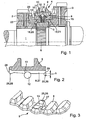
- 1 denotes a shaft of a gearbox for motor vehicles, on which two gear wheels 2 and 3 are freely rotatably mounted. Between these two gear wheels 2 and 3, a synchronizer 4 is arranged, via which either one of the two gear wheels 2 or 3 at the shaft 1 can be coupled. In this way, the gearbox is switched to different gear ratios.
- the synchronizing device 4 has a synchronizer body 5, which engages in rotation in a toothing 6 of the shaft 1. Furthermore, the synchronizer body 5 is provided at its outer periphery with an external toothing 7, in which teeth 8 engage an internal toothing of a sliding sleeve 9. In the synchronizer body 5, a pressure piece 10 is further guided with a compression spring 11 which receives a spherical, in the longitudinal direction over the pressure piece 10 projecting locking element 12. The spherical detent element 12 protrudes from the synchronizer body 5 to approximately the tip circle of the external toothing 7.
- synchronizer rings 14 and 15 On both sides of the pressure piece 10 synchronizer rings 14 and 15 are arranged, the outside have a locking teeth 16 and 17 and inside a friction surface 18 and 19 respectively.
- the friction surfaces 18 and 19 of the synchronizer rings 14 and 15 cooperate with correspondingly formed friction surfaces 20 and 21 which are formed on the gear wheel 3 and on a rotatably connected to the gear 2 clutch ring 22.
- the inventive construction of the sliding sleeve 9 can be seen in Figures 2 and 3.
- the locking element 12 is first taken from this and exerts an axial force on the respective synchronizer ring 14 and 15 via the pressure piece 10.
- the locking element 12 disengages from the locking groove 13 and moves on the Riegelutzahnahn 27.
- the movement of the locking element 12 on the Riegelut leopard 27 is limited by outwardly by locking stages 28. As a result, the latching element 12 does not move beyond the barge 27 and thus does not snag behind the barge 27.
- the locking stage 28 is formed as a radially inwardly projecting projection 25, 26.
- various forms of training in particular rectangular or truncated pyramidal projections 26.
- the projection 25 has a radius of the locking element 12 adapted negative radius.
- the latching element 12 rests evenly on the projection 25 in the end position, as a result of which force peaks which arise in the projection 26 along a support line are avoided.
- Another way to avoid undesirable deformation of the projections 25, 26 is to harden them. All standard hardening methods can be used.
- the bartack 27 may be formed slightly sloping at its axial ends 29. Such a contour can not be realized without a projection, since this favors the unwanted lateral emigration of the locking element 12 from the bartack 27.
Landscapes
- Engineering & Computer Science (AREA)
- General Engineering & Computer Science (AREA)
- Mechanical Engineering (AREA)
- Mechanical Operated Clutches (AREA)
Claims (5)
- Dispositif pour la sélection d'au moins une roue dentée (2, 3) au moyen d'un manchon coulissant (9) qui peut être déplacé en direction de la roue dentée (2, 3) à partir d'une position neutre, ledit manchon coulissant (9) comprenant des dents (8) pour l'engagement, lesquels dents (8), en étant configurées sous la forme de dents (27) à rainure de verrouillage, sont munies, au moins partiellement, d'une rainure de verrouillage (13), ledit dispositif étant muni d'au moins un anneau de synchronisation (14, 15) par roue dentée (2, 3) pour une synchronisation de vitesses de rotation de la roue dentée (2, 3), ledit dispositif étant muni, en plus, d'au moins un membre de la poussée (10) qui peut être déplacé en direction de l'au moins une roue dentée (2, 3) par le manchon coulissant (9), ledit membre de la poussée (10) s'engageant, dans la position neutre du manchon coulissant (9), dans la rainure de verrouillage (13), et l'anneau de synchronisation (14, 15) étant agencé dans le dispositif en étant déplaçable, au moins de manière limitée, par le membre de la poussée (10) en direction de la roue dentée (2, 3) pour amorcer le synchronisation, caractérisé en ce que les dents (27) à rainure de verrouillage comprennent, à leur extrémité axiale (29), un gradin de blocage (28).
- Dispositif selon la revendication 1, caractérisé en ce que le gradin de blocage (28) est configuré sous la forme d'une saillie (25, 26) orientée radialement vers l'intérieur.
- Dispositif selon la revendication 2, caractérisé en ce que la saillie (25, 26) a une configuration axialement symétrique et son contour négatif orienté vers l'intérieur a un rayon qui correspond à celui du membre de la poussée (10).
- Dispositif selon la revendication 2, caractérisé en ce que la saillie (25, 26) est configurée sous la forme d'un parallélépipède.
- Dispositif selon la revendication 1, caractérisé en ce que le gradin de blocage (28) est durci.
Applications Claiming Priority (1)
| Application Number | Priority Date | Filing Date | Title |
|---|---|---|---|
| DE102004051421A DE102004051421A1 (de) | 2004-10-22 | 2004-10-22 | Vorrichtung zum Schalten zweier Gangräder mittels einer aus einer neutralen Stellung in Richtung der Gangräder verschiebbaren Schiebemuffe |
Publications (2)
| Publication Number | Publication Date |
|---|---|
| EP1650457A1 EP1650457A1 (fr) | 2006-04-26 |
| EP1650457B1 true EP1650457B1 (fr) | 2007-05-02 |
Family
ID=35169754
Family Applications (1)
| Application Number | Title | Priority Date | Filing Date |
|---|---|---|---|
| EP05018648A Active EP1650457B1 (fr) | 2004-10-22 | 2005-08-27 | Système de changement de vitesse |
Country Status (2)
| Country | Link |
|---|---|
| EP (1) | EP1650457B1 (fr) |
| DE (2) | DE102004051421A1 (fr) |
Families Citing this family (8)
| Publication number | Priority date | Publication date | Assignee | Title |
|---|---|---|---|---|
| DE102006060535A1 (de) * | 2006-12-21 | 2008-06-26 | Schaeffler Kg | Synchronisiereinrichtung für ein Schaltgetriebe |
| FR2949833B1 (fr) * | 2009-09-09 | 2012-01-20 | Renault Sa | Synchroniseur pour boite de vitesses de vehicule automobile a inserts rapportes. |
| DE102010017922A1 (de) | 2010-04-22 | 2011-10-27 | Dr. Ing. H.C. F. Porsche Aktiengesellschaft | Getriebe |
| DE102010019453A1 (de) * | 2010-05-05 | 2011-11-10 | Hoerbiger Antriebstechnik Gmbh | Vorsynchroneinheit eines Schaltgetriebes |
| DE102011084257B3 (de) * | 2011-10-11 | 2013-01-03 | Schaeffler Technologies AG & Co. KG | Synchronisiereinrichtung für ein Zahnräderwechselgetriebe |
| DE102012223761A1 (de) | 2012-12-19 | 2014-07-10 | Schaeffler Technologies Gmbh & Co. Kg | Schiebemuffe eines Gangräderwechselgetriebes mit einer Innenverzahnung |
| DE102016212838B3 (de) * | 2016-07-14 | 2017-09-21 | Schaeffler Technologies AG & Co. KG | Multifunktionaler Riegelnutzahn |
| DE102019113980A1 (de) * | 2019-05-24 | 2020-11-26 | Schaeffler Technologies AG & Co. KG | Druckstück und Synchronisierung mit einem Druckstück |
Family Cites Families (10)
| Publication number | Priority date | Publication date | Assignee | Title |
|---|---|---|---|---|
| DE2141261A1 (de) * | 1971-08-18 | 1973-02-22 | Daimler Benz Ag | Mechanisch synchronisiertes schaltgetriebe |
| DE2510657A1 (de) * | 1975-03-12 | 1976-09-23 | Helmut Droeschel | Zahnkupplung in zahnradwechselgetriebe mit stirnverzahnung und synchronisierung |
| US4059178A (en) * | 1976-07-16 | 1977-11-22 | Zahnradfabrik Friedrichshafen Aktiengesellschaft | Gear-shifting jaw clutch for speed-changing vehicular transmission |
| US4998445A (en) * | 1989-11-01 | 1991-03-12 | Tanaka Seimitu Kogyo Kabushiki Kaisha | Synchronizer ring |
| GB9107771D0 (en) | 1991-04-12 | 1991-05-29 | Eaton Corp | Synchroniser sliding sleeve |
| FR2676791B1 (fr) * | 1991-05-24 | 1993-08-06 | Renault | Synchroniseur de boite de vitesses. |
| DE4404093C2 (de) * | 1994-02-09 | 1996-08-14 | Porsche Ag | Vorrichtung zum Schalten eines Getriebes über eine Synchronisiereinrichtung |
| DE19847139C1 (de) * | 1998-10-13 | 2000-05-11 | Hoerbiger & Co | Sperr-Synchronring für synchronisierte Schaltgetriebe |
| DE19932300A1 (de) * | 1999-07-10 | 2001-01-25 | Schaeffler Waelzlager Ohg | Schiebemuffe einer Synchronisiereinheit für Schaltgetriebe |
| DE10164203C1 (de) * | 2001-12-27 | 2003-04-30 | Getrag Synchron Technik Gmbh | Schaltkupplung für ein Stirnradgetriebe |
-
2004
- 2004-10-22 DE DE102004051421A patent/DE102004051421A1/de not_active Withdrawn
-
2005
- 2005-08-27 EP EP05018648A patent/EP1650457B1/fr active Active
- 2005-08-27 DE DE502005000656T patent/DE502005000656D1/de active Active
Also Published As
| Publication number | Publication date |
|---|---|
| EP1650457A1 (fr) | 2006-04-26 |
| DE102004051421A1 (de) | 2006-04-27 |
| DE502005000656D1 (de) | 2007-06-14 |
Similar Documents
| Publication | Publication Date | Title |
|---|---|---|
| EP1650457B1 (fr) | Système de changement de vitesse | |
| EP2475907B1 (fr) | Synchronisation pour une boîte de vitesses | |
| EP2478242B1 (fr) | Ensemble comportant deux bagues de synchronisation | |
| EP2235391B1 (fr) | Élément amplificateur de force | |
| DE10024658A1 (de) | Synchronisiereinrichtung für ein Handschaltgetriebe | |
| EP2260214B1 (fr) | Dispositif d'arrêt | |
| EP2092206B1 (fr) | Manchon coulissant d'un dispositif de synchronisation | |
| EP2012036A2 (fr) | Arrêt | |
| EP1664566B1 (fr) | Embrayage de synchronisation pour un engrenage reducteur de vehicule automobile | |
| DE102006060535A1 (de) | Synchronisiereinrichtung für ein Schaltgetriebe | |
| DE102016104495A1 (de) | Schiebemuffe einer Synchronisationsvorrichtung für ein Schaltgetriebe sowie Verfahren zum Herstellen einer solchen Schiebemuffe | |
| EP1788271B1 (fr) | Synchroniseur | |
| WO2008028784A1 (fr) | Corps synchrone | |
| EP2366070A1 (fr) | Agencement de commutation pour le passage de la marche arrière sur une boîte de vitesses à engrenages, ainsi que boîte de vitesses à engrenages | |
| DE102008049978A1 (de) | Schalteinheit mit Kupplungskörper | |
| EP1192364A1 (fr) | Manchon coulissant d'une unite de synchronisation pour boites de vitesses | |
| DE1630450B2 (de) | Mechanische schalteinrichtung mit synchronisierter zahnkupplung fuer ein zahnraederwechselgetriebe | |
| WO2007074031A1 (fr) | Dispositif de synchronisation | |
| DE102005061481A1 (de) | Schaltvorrichtung | |
| DE19938934A1 (de) | Getriebe | |
| EP1239175B1 (fr) | Embrayage avec un dispositif de synchronisation | |
| DE102005059733A1 (de) | Schaltkupplung | |
| EP2478244B1 (fr) | Manchon d'actionnement pour boîte de vitesses mécanique | |
| DE10161596A1 (de) | Synchronisierung | |
| DE19848253A1 (de) | Kupplungseinrichtung mit einem an einer Schwungmasse vorgesehenen Aufnehmer für einen Mitnehmer |
Legal Events
| Date | Code | Title | Description |
|---|---|---|---|
| PUAI | Public reference made under article 153(3) epc to a published international application that has entered the european phase |
Free format text: ORIGINAL CODE: 0009012 |
|
| 17P | Request for examination filed |
Effective date: 20050827 |
|
| AK | Designated contracting states |
Kind code of ref document: A1 Designated state(s): AT BE BG CH CY CZ DE DK EE ES FI FR GB GR HU IE IS IT LI LT LU LV MC NL PL PT RO SE SI SK TR |
|
| AX | Request for extension of the european patent |
Extension state: AL BA HR MK YU |
|
| 17Q | First examination report despatched |
Effective date: 20060713 |
|
| GRAP | Despatch of communication of intention to grant a patent |
Free format text: ORIGINAL CODE: EPIDOSNIGR1 |
|
| AKX | Designation fees paid |
Designated state(s): CZ DE FR IT |
|
| GRAS | Grant fee paid |
Free format text: ORIGINAL CODE: EPIDOSNIGR3 |
|
| GRAA | (expected) grant |
Free format text: ORIGINAL CODE: 0009210 |
|
| AK | Designated contracting states |
Kind code of ref document: B1 Designated state(s): CZ DE FR IT |
|
| REF | Corresponds to: |
Ref document number: 502005000656 Country of ref document: DE Date of ref document: 20070614 Kind code of ref document: P |
|
| ET | Fr: translation filed | ||
| PLBE | No opposition filed within time limit |
Free format text: ORIGINAL CODE: 0009261 |
|
| STAA | Information on the status of an ep patent application or granted ep patent |
Free format text: STATUS: NO OPPOSITION FILED WITHIN TIME LIMIT |
|
| 26N | No opposition filed |
Effective date: 20080205 |
|
| REG | Reference to a national code |
Ref country code: DE Ref legal event code: R081 Ref document number: 502005000656 Country of ref document: DE Owner name: SCHAEFFLER TECHNOLOGIES AG & CO. KG, DE Free format text: FORMER OWNER: SCHAEFFLER TECHNOLOGIES GMBH & CO. KG, 91074 HERZOGENAURACH, DE Effective date: 20120828 Ref country code: DE Ref legal event code: R081 Ref document number: 502005000656 Country of ref document: DE Owner name: SCHAEFFLER TECHNOLOGIES GMBH & CO. KG, DE Free format text: FORMER OWNER: SCHAEFFLER TECHNOLOGIES GMBH & CO. KG, 91074 HERZOGENAURACH, DE Effective date: 20120828 |
|
| REG | Reference to a national code |
Ref country code: DE Ref legal event code: R081 Ref document number: 502005000656 Country of ref document: DE Owner name: SCHAEFFLER TECHNOLOGIES AG & CO. KG, DE Free format text: FORMER OWNER: SCHAEFFLER TECHNOLOGIES AG & CO. KG, 91074 HERZOGENAURACH, DE Effective date: 20140217 Ref country code: DE Ref legal event code: R081 Ref document number: 502005000656 Country of ref document: DE Owner name: SCHAEFFLER TECHNOLOGIES GMBH & CO. KG, DE Free format text: FORMER OWNER: SCHAEFFLER TECHNOLOGIES AG & CO. KG, 91074 HERZOGENAURACH, DE Effective date: 20140217 |
|
| REG | Reference to a national code |
Ref country code: DE Ref legal event code: R081 Ref document number: 502005000656 Country of ref document: DE Owner name: SCHAEFFLER TECHNOLOGIES AG & CO. KG, DE Free format text: FORMER OWNER: SCHAEFFLER TECHNOLOGIES GMBH & CO. KG, 91074 HERZOGENAURACH, DE Effective date: 20150213 |
|
| REG | Reference to a national code |
Ref country code: FR Ref legal event code: PLFP Year of fee payment: 11 |
|
| REG | Reference to a national code |
Ref country code: FR Ref legal event code: PLFP Year of fee payment: 12 |
|
| REG | Reference to a national code |
Ref country code: FR Ref legal event code: PLFP Year of fee payment: 13 |
|
| REG | Reference to a national code |
Ref country code: FR Ref legal event code: PLFP Year of fee payment: 14 |
|
| PGFP | Annual fee paid to national office [announced via postgrant information from national office to epo] |
Ref country code: IT Payment date: 20220825 Year of fee payment: 18 Ref country code: CZ Payment date: 20220825 Year of fee payment: 18 |
|
| PGFP | Annual fee paid to national office [announced via postgrant information from national office to epo] |
Ref country code: DE Payment date: 20221019 Year of fee payment: 18 |
|
| P01 | Opt-out of the competence of the unified patent court (upc) registered |
Effective date: 20230522 |
|
| PGFP | Annual fee paid to national office [announced via postgrant information from national office to epo] |
Ref country code: FR Payment date: 20230822 Year of fee payment: 19 |
|
| REG | Reference to a national code |
Ref country code: DE Ref legal event code: R119 Ref document number: 502005000656 Country of ref document: DE |
|
| PG25 | Lapsed in a contracting state [announced via postgrant information from national office to epo] |
Ref country code: CZ Free format text: LAPSE BECAUSE OF NON-PAYMENT OF DUE FEES Effective date: 20230827 |