EP1650457B1 - Gear-shifting device - Google Patents
Gear-shifting device Download PDFInfo
- Publication number
- EP1650457B1 EP1650457B1 EP05018648A EP05018648A EP1650457B1 EP 1650457 B1 EP1650457 B1 EP 1650457B1 EP 05018648 A EP05018648 A EP 05018648A EP 05018648 A EP05018648 A EP 05018648A EP 1650457 B1 EP1650457 B1 EP 1650457B1
- Authority
- EP
- European Patent Office
- Prior art keywords
- sliding sleeve
- gearwheel
- gear
- teeth
- locking
- Prior art date
- Legal status (The legal status is an assumption and is not a legal conclusion. Google has not performed a legal analysis and makes no representation as to the accuracy of the status listed.)
- Active
Links
- 230000007935 neutral effect Effects 0.000 claims description 11
- 238000000034 method Methods 0.000 claims description 6
- 230000004888 barrier function Effects 0.000 claims 3
- 230000000977 initiatory effect Effects 0.000 claims 1
- 230000005540 biological transmission Effects 0.000 description 4
- 238000004519 manufacturing process Methods 0.000 description 4
- 230000000903 blocking effect Effects 0.000 description 3
- 230000008878 coupling Effects 0.000 description 3
- 238000010168 coupling process Methods 0.000 description 3
- 238000005859 coupling reaction Methods 0.000 description 3
- 238000006073 displacement reaction Methods 0.000 description 3
- 230000006835 compression Effects 0.000 description 2
- 238000007906 compression Methods 0.000 description 2
- 230000000694 effects Effects 0.000 description 2
- 238000000418 atomic force spectrum Methods 0.000 description 1
- 238000005452 bending Methods 0.000 description 1
- 238000010276 construction Methods 0.000 description 1
- 238000005520 cutting process Methods 0.000 description 1
- 230000006866 deterioration Effects 0.000 description 1
- 238000005516 engineering process Methods 0.000 description 1
- 238000005096 rolling process Methods 0.000 description 1
Images
Classifications
-
- F—MECHANICAL ENGINEERING; LIGHTING; HEATING; WEAPONS; BLASTING
- F16—ENGINEERING ELEMENTS AND UNITS; GENERAL MEASURES FOR PRODUCING AND MAINTAINING EFFECTIVE FUNCTIONING OF MACHINES OR INSTALLATIONS; THERMAL INSULATION IN GENERAL
- F16D—COUPLINGS FOR TRANSMITTING ROTATION; CLUTCHES; BRAKES
- F16D23/00—Details of mechanically-actuated clutches not specific for one distinct type
- F16D23/02—Arrangements for synchronisation, also for power-operated clutches
- F16D23/04—Arrangements for synchronisation, also for power-operated clutches with an additional friction clutch
- F16D23/06—Arrangements for synchronisation, also for power-operated clutches with an additional friction clutch and a blocking mechanism preventing the engagement of the main clutch prior to synchronisation
- F16D2023/0618—Details of blocking mechanism comprising a helical spring loaded element, e.g. ball
-
- F—MECHANICAL ENGINEERING; LIGHTING; HEATING; WEAPONS; BLASTING
- F16—ENGINEERING ELEMENTS AND UNITS; GENERAL MEASURES FOR PRODUCING AND MAINTAINING EFFECTIVE FUNCTIONING OF MACHINES OR INSTALLATIONS; THERMAL INSULATION IN GENERAL
- F16D—COUPLINGS FOR TRANSMITTING ROTATION; CLUTCHES; BRAKES
- F16D23/00—Details of mechanically-actuated clutches not specific for one distinct type
- F16D23/02—Arrangements for synchronisation, also for power-operated clutches
- F16D23/04—Arrangements for synchronisation, also for power-operated clutches with an additional friction clutch
- F16D23/06—Arrangements for synchronisation, also for power-operated clutches with an additional friction clutch and a blocking mechanism preventing the engagement of the main clutch prior to synchronisation
- F16D2023/0631—Sliding sleeves; Details thereof
-
- F—MECHANICAL ENGINEERING; LIGHTING; HEATING; WEAPONS; BLASTING
- F16—ENGINEERING ELEMENTS AND UNITS; GENERAL MEASURES FOR PRODUCING AND MAINTAINING EFFECTIVE FUNCTIONING OF MACHINES OR INSTALLATIONS; THERMAL INSULATION IN GENERAL
- F16D—COUPLINGS FOR TRANSMITTING ROTATION; CLUTCHES; BRAKES
- F16D23/00—Details of mechanically-actuated clutches not specific for one distinct type
- F16D23/02—Arrangements for synchronisation, also for power-operated clutches
- F16D23/04—Arrangements for synchronisation, also for power-operated clutches with an additional friction clutch
- F16D23/06—Arrangements for synchronisation, also for power-operated clutches with an additional friction clutch and a blocking mechanism preventing the engagement of the main clutch prior to synchronisation
- F16D2023/0656—Details of the tooth structure; Arrangements of teeth
- F16D2023/0668—Details relating to tooth end or tip geometry
Definitions
- the invention relates to a device for switching two gear wheels by means of a displaceable from a neutral position in the direction of the gear wheels sliding sleeve having teeth for engagement, which are partially provided with a locking groove, wherein the device with at least one synchronizer ring per gear wheel for synchronizing Speeds of the gear wheel is provided with at least one displaceable by the sliding sleeve in the direction of the gear wheels pressure piece which engages in the locking position of the sliding sleeve in the locking groove and the synchronizer ring for Ansynchron ensue is at least limited by means of the pressure piece in the direction of the gear wheel slidably disposed in the device.
- Such sliding sleeves are usually as coupling elements in synchronizers used by modern manual automotive transmissions. They connect a gear shaft rotationally fixed with a rotatably mounted on the transmission shaft gear.
- the sliding sleeve is arranged concentrically to the transmission shaft, rotationally fixed and slidable in the longitudinal direction of the transmission shaft and coupled with a gear wheel on a synchronizer body.
- Sliding sleeves are available in various designs. In most cases, they have on their inner lateral surface on an inwardly facing toothing, which engages in a counter-toothing of the synchronizer body and in the switched state in a toothing of the gear wheel. On the outer circumference of the sliding sleeve a guide for a shift fork is provided. With the shift fork, the sliding sleeve is moved in the longitudinal direction on the synchronizer body until it is connected to the gear or moved back to its neutral position.
- the sliding sleeves are often held axially by a locking element which is received in the synchronizer body and usually spring-loaded acts on a recess.
- the recess is, depending on the design of the detent, formed on individual or all inwardly directed teeth of the sliding sleeve.
- the locking element causes the sliding sleeve can only be moved axially after overcoming a defined resistance by the operator, when switching the gear, and does not move unintentionally and automatically in the axial direction.
- z. B. for a neutral and a detent position, set or to define displacement forces and force profiles of different heights, often two or more recesses in the longitudinal direction of the tooth are arranged one behind the other.
- the plungers serve as an actuator for the process of Vorsynchronmaschine. With axial displacement the sliding sleeve, the plungers are taken axially by them. They initiate the process of synchronization by acting on arranged between the gear and the synchronizer synchronizer rings.
- the tooth contour has a smooth surface.
- the sliding sleeve is moved from the neutral position or from a second end position to a first end position, wherein the sliding sleeve via the pressure piece in a first movement step, the synchronization, an adjustment of the different speeds between the gear and the synchronizer body, initiates.
- EP 508 639 B1 proposes to provide a plurality of latching or retaining recesses in the sliding sleeve.
- a disadvantage of this solution is that on the one hand, these locking recesses are exposed to wear, on the other hand, the contour is elaborate to manufacture.
- the invention is therefore based on the object to provide a device in which the aforementioned disadvantages are eliminated.
- this object is achieved by the features of the characterizing part of claim 1, characterized in that the teeth provided with the locking groove have a locking step at its axial end. If, in the sliding sleeve according to the invention, a gear change from the neutral position or from a second end position into a first end position, then the locking element can move on the Riegelutzahn, but not beyond the locking level addition. Thus, it can not in particular ansynchon are the non-engaged gear by being supported on an edge of the Riegelutzahns.
- the locking step also makes it possible to vary the shape of the locking groove in the axial direction. It may, for example, have a sloping towards the end faces profile without the risk that the locking element migrates through play and vibration on the sliding sleeve addition.
- a particularly advantageous embodiment of the invention is to form the locking stage as a radially inwardly projecting projection, which can be easily realized in terms of manufacturing technology. Especially in non-cutting produced sliding sleeves, it can be easily and inexpensively introduced by a stamping process in the bartenders. Alternatively, however, bending, rolling or stamping methods for producing the projection are also conceivable, for example.
- a further embodiment of the invention provides for forming the projection in such a way that its surface corresponds to a negative impression of the detent element, as seen axially inwardly, so that in the case of its lateral emigration is distributed by this force as evenly as possible on the projection.
- the projection according to the invention is simple to manufacture and therefore inexpensive to manufacture. A complex to finished contour is not required.
- 1 denotes a shaft of a gearbox for motor vehicles, on which two gear wheels 2 and 3 are freely rotatably mounted. Between these two gear wheels 2 and 3, a synchronizer 4 is arranged, via which either one of the two gear wheels 2 or 3 at the shaft 1 can be coupled. In this way, the gearbox is switched to different gear ratios.
- the synchronizing device 4 has a synchronizer body 5, which engages in rotation in a toothing 6 of the shaft 1. Furthermore, the synchronizer body 5 is provided at its outer periphery with an external toothing 7, in which teeth 8 engage an internal toothing of a sliding sleeve 9. In the synchronizer body 5, a pressure piece 10 is further guided with a compression spring 11 which receives a spherical, in the longitudinal direction over the pressure piece 10 projecting locking element 12. The spherical detent element 12 protrudes from the synchronizer body 5 to approximately the tip circle of the external toothing 7.
- synchronizer rings 14 and 15 On both sides of the pressure piece 10 synchronizer rings 14 and 15 are arranged, the outside have a locking teeth 16 and 17 and inside a friction surface 18 and 19 respectively.
- the friction surfaces 18 and 19 of the synchronizer rings 14 and 15 cooperate with correspondingly formed friction surfaces 20 and 21 which are formed on the gear wheel 3 and on a rotatably connected to the gear 2 clutch ring 22.
- the inventive construction of the sliding sleeve 9 can be seen in Figures 2 and 3.
- the locking element 12 is first taken from this and exerts an axial force on the respective synchronizer ring 14 and 15 via the pressure piece 10.
- the locking element 12 disengages from the locking groove 13 and moves on the Riegelutzahnahn 27.
- the movement of the locking element 12 on the Riegelut leopard 27 is limited by outwardly by locking stages 28. As a result, the latching element 12 does not move beyond the barge 27 and thus does not snag behind the barge 27.
- the locking stage 28 is formed as a radially inwardly projecting projection 25, 26.
- various forms of training in particular rectangular or truncated pyramidal projections 26.
- the projection 25 has a radius of the locking element 12 adapted negative radius.
- the latching element 12 rests evenly on the projection 25 in the end position, as a result of which force peaks which arise in the projection 26 along a support line are avoided.
- Another way to avoid undesirable deformation of the projections 25, 26 is to harden them. All standard hardening methods can be used.
- the bartack 27 may be formed slightly sloping at its axial ends 29. Such a contour can not be realized without a projection, since this favors the unwanted lateral emigration of the locking element 12 from the bartack 27.
Description
Die Erfindung betrifft eine Vorrichtung zum Schalten zweier Gangräder mittels einer aus einer neutralen Stellung in Richtung der Gangräder verschiebbaren Schiebemuffe, welche Zähne zum Eingriff aufweist, die teilweise mit einer Riegelnut versehen sind, wobei die Vorrichtung mit wenigstens je einem Synchronring pro Gangrad für ein Synchronisieren von Drehzahlen des Gangrads versehen ist, mit mindestens einem durch die Schiebemuffe in Richtung der Gangräder verschiebbaren Druckstück, das in Neutralstellung der Schiebemuffe in die Riegelnut eingreift und der Synchronring zum Ansynchronisieren zumindest begrenzt mittels des Druckstücks in Richtung des Gangrads verschiebbar in der Vorrichtung angeordnet ist.The invention relates to a device for switching two gear wheels by means of a displaceable from a neutral position in the direction of the gear wheels sliding sleeve having teeth for engagement, which are partially provided with a locking groove, wherein the device with at least one synchronizer ring per gear wheel for synchronizing Speeds of the gear wheel is provided with at least one displaceable by the sliding sleeve in the direction of the gear wheels pressure piece which engages in the locking position of the sliding sleeve in the locking groove and the synchronizer ring for Ansynchronisieren is at least limited by means of the pressure piece in the direction of the gear wheel slidably disposed in the device.
Derartige Schiebemuffen sind in der Regel als Kupplungselemente in Synchronisiereinrichtungen von modernen handgeschalteten Kraftfahrzeuggetrieben eingesetzt. Sie verbinden eine Getriebewelle verdrehfest mit einem auf der Getriebewelle drehbar gelagerten Gangrad. Dabei sitzt die Schiebemuffe konzentrisch zur Getriebewelle angeordnet, verdrehfest und in Längsrichtung der Getriebewelle verschiebbar sowie mit einem Gangrad kuppelbar auf einem Synchronkörper.Such sliding sleeves are usually as coupling elements in synchronizers used by modern manual automotive transmissions. They connect a gear shaft rotationally fixed with a rotatably mounted on the transmission shaft gear. In this case, the sliding sleeve is arranged concentrically to the transmission shaft, rotationally fixed and slidable in the longitudinal direction of the transmission shaft and coupled with a gear wheel on a synchronizer body.
Schiebemuffen gibt es in den verschiedensten Ausführungen. Zumeist weisen sie an ihrer Innenmantelfläche eine nach innen weisende Verzahnung auf, die in eine Gegenverzahnung des Synchronkörpers und im geschalteten Zustand in eine Verzahnung des Gangrades eingreift. Am Außenumfang der Schiebemuffe ist eine Führung für eine Schaltgabel vorgesehen. Mit der Schaltgabel wird die Schiebemuffe in Längsrichtung auf dem Synchronkörper verschoben, bis sie mit dem Zahnrad verbunden oder wieder zurück in ihre Neutralstellung bewegt ist.Sliding sleeves are available in various designs. In most cases, they have on their inner lateral surface on an inwardly facing toothing, which engages in a counter-toothing of the synchronizer body and in the switched state in a toothing of the gear wheel. On the outer circumference of the sliding sleeve a guide for a shift fork is provided. With the shift fork, the sliding sleeve is moved in the longitudinal direction on the synchronizer body until it is connected to the gear or moved back to its neutral position.
In der Neutralstellung werden die Schiebemuffen oft axial durch ein Rastelement gehalten, das im Synchronkörper aufgenommen ist und zumeist federbelastet auf eine Ausnehmung wirkt. Die Ausnehmung ist, je nach Ausführung der Rastierung, an einzelnen oder allen nach innen gerichteten Zähnen der Schiebemuffe ausgebildet. Das Rastelement bewirkt, dass die Schiebemuffe erst nach dem Überwinden eines definierten Widerstandes durch die Bedienperson, beim Schalten des Ganges, axial bewegt werden kann und sich nicht unbeabsichtigt und selbsttätig in axiale Richtung verschiebt. Um verschiedene Rastpunkte, z. B. für eine Neutral- und eine Raststellung, festzulegen oder Verschiebekräfte und Kraftverläufe unterschiedlicher Höhe zu definieren, sind häufig zwei oder mehr Ausnehmungen in Längsrichtung des Zahnes hintereinander angeordnet.In the neutral position, the sliding sleeves are often held axially by a locking element which is received in the synchronizer body and usually spring-loaded acts on a recess. The recess is, depending on the design of the detent, formed on individual or all inwardly directed teeth of the sliding sleeve. The locking element causes the sliding sleeve can only be moved axially after overcoming a defined resistance by the operator, when switching the gear, and does not move unintentionally and automatically in the axial direction. To different Rastpunkte, z. B. for a neutral and a detent position, set or to define displacement forces and force profiles of different heights, often two or more recesses in the longitudinal direction of the tooth are arranged one behind the other.
Neben oder unabhängig von den vorgenannten Rastelementen wirken bei anderen Synchronisiereinrichtungen auf die Ausnehmungen des nach innen gerichteten Zahnes Druckstücke oder Sperrelemente. Die Druckstücke dienen als Betätigungselement für den Prozess der Vorsynchronisierung. Bei axialem Verschieben der Schiebemuffe werden die Druckstücke axial durch diese mitgenommen. Dabei leiten sie den Prozess der Synchronisation ein, indem sie auf zwischen dem Gangrad und dem Synchronkörper angeordnete Synchronringe wirken.In addition to or independently of the aforementioned locking elements act in other synchronizers on the recesses of the inwardly directed tooth thrust pieces or locking elements. The plungers serve as an actuator for the process of Vorsynchronisierung. With axial displacement the sliding sleeve, the plungers are taken axially by them. They initiate the process of synchronization by acting on arranged between the gear and the synchronizer synchronizer rings.
Von den Ausnehmungen abgesehen weist die Zahnkontur eine glatte Oberfläche auf. Bei einem Gangwechsel wird die Schiebemuffe aus der Neutralstellung oder aus einer zweiten Endstellung in eine erste Endstellung verschoben, wobei die Schiebemuffe über das Druckstück in einem ersten Bewegungsschritt die Ansynchronisation, ein Angleichen der unterschiedlichen Drehzahlen zwischen dem Gangrad und dem Synchronkörper, einleitet.Apart from the recesses, the tooth contour has a smooth surface. In a gear change, the sliding sleeve is moved from the neutral position or from a second end position to a first end position, wherein the sliding sleeve via the pressure piece in a first movement step, the synchronization, an adjustment of the different speeds between the gear and the synchronizer body, initiates.
Bei zunehmendem, laufzeitbedingtem Verschleiß der Synchronisiereinrichtung kann das Druckstück im geschalteten Zustand der Schiebemuffe immer weiter in den Endbereich des Riegelnutzahns gelangen. Dies führt schließlich dazu, dass im Extremfall das Druckstück über den Endbereich des Riegelnutzahns hinaus gelangt, sich an der Zahnkante abstützt und somit beim Auslegen des Gangs in Richtung des gegenüberliegenden Synchronringpakets geschoben wird. Dies führt zu einer ständigen, ungewünschten Ansynchronisation des nicht eingelegten Gangs und folglich zu einem Verschleiß der Vorrichtung. Begünstigt wird ein derartiger Effekt umso mehr, wenn der Riegelnutzahn so geformt ist, dass er stirnseitig ein leicht abfallendes Profil aufweist.With increasing, run-time wear of the synchronizer, the pressure piece in the switched state of the sliding sleeve can get further and further into the end of the Riegelutzahns. This ultimately leads to the fact that in extreme cases, the pressure piece reaches beyond the end portion of the Riegelutzahns out, is supported on the tooth edge and thus pushed in the design of the gear in the direction of the opposite synchronizer ring package. This leads to a constant, unwanted Ansynchronisation of the non-engaged gear and thus to a deterioration of the device. Such an effect is favored even more if the bar tackle is shaped such that it has a slightly sloping profile on the face side.
Die Ausnehmung, in der sich das Druckstück in der Neutralstellung befindet, dient dazu, dem Bediener eine haptische Rückmeldung beim Durchschalten der Neutralstellung zu vermitteln. Sie ist insbesondere nicht dafür vorgesehen, das Druckstück fest zu führen. Um bei einem laufzeitbedingtem Verschleiß das Problem der ungewollten Ansynchronisation zu vermeiden, ist in der EP 508 639 B1 vorgeschlagen, in der Schiebemuffe mehrere Rast- oder Halteausnehmungen vorzusehen. Nachteilig an dieser Lösung ist aber, dass einerseits auch diese Rastausnehmungen einem Verschleiß ausgesetzt sind, andererseits der Konturverlauf aufwändig zu fertigen ist.The recess, in which the pressure piece is in the neutral position, serves to provide the user with haptic feedback when switching through the neutral position. It is not intended in particular to guide the pressure piece firmly. In order to avoid the problem of unwanted synchronization in case of wear due to running time, EP 508 639 B1 proposes to provide a plurality of latching or retaining recesses in the sliding sleeve. A disadvantage of this solution, however, is that on the one hand, these locking recesses are exposed to wear, on the other hand, the contour is elaborate to manufacture.
Der Erfindung liegt deshalb die Aufgabe zugrunde, eine Vorrichtung zu schaffen, bei der die vorstehend genannten Nachteile beseitigt sind.The invention is therefore based on the object to provide a device in which the aforementioned disadvantages are eliminated.
Erfindungsgemäß wird diese Aufgabe nach den Merkmalen des kennzeichnenden Teils des Anspruchs 1 dadurch gelöst, dass die mit der Riegelnut versehenen Zähne an ihrem axialen Ende eine Sperrstufe aufweisen. Erfolgt bei der erfindungsgemäßen Schiebemuffe ein Gangwechsel aus der Neutralstellung oder aus einer zweiten Endstellung in eine erste Endstellung, so kann das Rastelement sich auf dem Riegelnutzahn bewegen, aber nicht über die Sperrstufe hinaus. Damit kann es insbesondere nicht den nicht eingelegten Gang ansynchonisieren, indem es sich an einer Kante des Riegelnutzahns abstützt.According to the invention, this object is achieved by the features of the characterizing part of
Die Sperrstufe ermöglicht es auch, die Form der Riegelnut in axialer Richtung zu variieren. Sie kann beispielsweise ein zu den Stirnseiten hin abfallendes Profil aufweisen, ohne dass die Gefahr besteht, dass das Rastelement durch Spiel und Vibrationen über die Schiebemuffe hinaus wandert.The locking step also makes it possible to vary the shape of the locking groove in the axial direction. It may, for example, have a sloping towards the end faces profile without the risk that the locking element migrates through play and vibration on the sliding sleeve addition.
Eine besonders vorteilhafte Ausführung der Erfindung ist es, die Sperrstufe als einen nach radial innen vorstehenden Vorsprung auszubilden, der fertigungstechnisch leicht realisiert werden kann. Insbesondere bei spanlos hergestellten Schiebemuffen kann er einfach und kostengünstig durch einen Prägevorgang in den Riegelnutzahn eingebracht werden. Alternativ sind aber auch beispielsweise Biege-, Walz- oder Stanzverfahren zur Herstellung des Vorsprungs denkbar.A particularly advantageous embodiment of the invention is to form the locking stage as a radially inwardly projecting projection, which can be easily realized in terms of manufacturing technology. Especially in non-cutting produced sliding sleeves, it can be easily and inexpensively introduced by a stamping process in the bartenders. Alternatively, however, bending, rolling or stamping methods for producing the projection are also conceivable, for example.
Damit die Sperrstufe die von der Rastkugel auf sie einwirkenden Kräfte optimal aufnehmen kann, sieht eine weitere Ausgestaltung der Erfindung vor, den Vorsprung derart auszubilden, dass seine Oberfläche nach axial innen gesehen einem negativen Abdruck des Rastelements entspricht, so dass im Falle seines seitlichen Auswanderns die von diesem ausgeübte Kraft möglichst gleichmäßig auf den Vorsprung verteilt wird.In order for the blocking stage to optimally absorb the forces acting on it by the detent ball, a further embodiment of the invention provides for forming the projection in such a way that its surface corresponds to a negative impression of the detent element, as seen axially inwardly, so that in the case of its lateral emigration is distributed by this force as evenly as possible on the projection.
Der erfindungsgemäße Vorsprung ist fertigungstechnisch einfach und somit auch kostengünstig herzustellen. Einer aufwändig zu fertigen Kontur bedarf es nicht.The projection according to the invention is simple to manufacture and therefore inexpensive to manufacture. A complex to finished contour is not required.
Die Erfindung wird nachfolgend anhand von einem Ausführungsbeispiel näher erläutert. Die dazugehörigen Zeichnungen zeigen dabei:
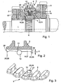
Figur 1- einen Längsschnitt eines Teils einer Synchronisiervorrichtung,
Figur 2- einen Längsschnitt einer erfindungsgemäßen Schiebemuffe einer Synchronisiervorrichtung,
Figur 3- eine perspektivische Schrägansicht auf einen Ausschnitt einer weiteren erfindungsgemäßen Schiebemuffe.
- FIG. 1
- a longitudinal section of a part of a synchronizing device,
- FIG. 2
- a longitudinal section of a sliding sleeve according to the invention a synchronizing device,
- FIG. 3
- a perspective oblique view of a section of another sliding sleeve according to the invention.
In Figur 1 ist mit 1 eine Welle eines Schaltgetriebes für Kraftfahrzeuge bezeichnet, auf welcher zwei Gangräder 2 und 3 frei drehbar gelagert sind. Zwischen diesen beiden Gangrädern 2 und 3 ist eine Synchronisiereinrichtung 4 angeordnet, über welche wahlweise eines der beiden Gangräder 2 oder 3 an die Welle 1 kuppelbar ist. Auf diese Weise wird das Schaltgetriebe in unterschiedliche Übersetzungsstufen geschaltet.In Figure 1, 1 denotes a shaft of a gearbox for motor vehicles, on which two
Die Synchronisiereinrichtung 4 weist einen Synchronkörper 5 auf, der drehfest in eine Verzahnung 6 der Welle 1 eingreift. Weiterhin ist der Synchronkörper 5 an seinem äußeren Umfang mit einer Außenverzahnung 7 versehen, in welche Zähne 8 einer Innenverzahnung einer Schiebemuffe 9 eingreifen. Im Synchronkörper 5 ist weiterhin ein Druckstück 10 mit einer Druckfeder 11 geführt, das ein kugelförmiges, in Längsrichtung über das Druckstück 10 vorstehendes Rastelement 12 aufnimmt. Das kugelförmige Rastelement 12 ragt dabei aus dem Synchronkörper 5 bis etwa zum Kopfkreis der Außenverzahnung 7 vor. In einer Neutralstellung der Synchronisiereinrichtung 4, in der keine der beiden möglichen Gangstufen geschaltet ist und sich somit die beiden Gangräder 2 und 3 frei gegenüber der Welle 1 drehen, greift das Rastelement 12 in eine in der Innenverzahnung 8 der Schiebemuffe 9 ausgebildete Riegelnut 13 eines Riegelnutzahns 27 (Figur 3) ein.The synchronizing
Beiderseits des Druckstücks 10 sind Synchronringe 14 und 15 angeordnet, die außen eine Sperrverzahnung 16 bzw. 17 und innen eine Reibfläche 18 bzw. 19 aufweisen. Die Reibflächen 18 und 19 der Synchronringe 14 und 15 wirken zusammen mit entsprechend ausgebildeten Reibflächen 20 und 21, welche am Gangrad 3 sowie an einem drehfest mit dem Gangrad 2 verbundenen Kupplungsring 22 ausgebildet sind.On both sides of the
Während eines Schaltvorgangs wird bei einer entsprechenden Sperrsynchronisierung über das Druckstück 10 zunächst während des Ansynchronisierens eine axiale Kraft auf den jeweiligen Synchronring 14 oder 15 ausgeübt, so dass dieser über seine Reibfläche 18 oder 19 von der entsprechenden Reibfläche 20 oder 21 mitgenommen und gegenüber dem Synchronkörper um einen bestimmten Winkel verdreht wird. In dieser Lage sperrt die Sperrverzahnung 16 eine weitere Verschiebung der Schiebemuffe 9. Diese Sperrwirkung wird erst dann aufgehoben, wenn Gleichlauf zwischen dem jeweiligen Gangrad 2 bzw. 3 und der Welle 1 erzielt ist. In diesem Moment wird die Innenverzahnung 8 der Schiebemuffe 9 durch die Sperrverzahnung 16 bzw. 17 hindurchbewegt und gelangt schließlich in Eingriff in einer Kuppelverzahnung 23 bzw. 24.During a switching operation, an axial force is exerted on the
Die erfindungsgemäße Ausbildung des Schiebemuffe 9 kann den Figuren 2 und 3 entnommen werden. Während einer Schaltbewegung der Schiebemuffe 9 wird zunächst das Rastelement 12 von dieser mitgenommen und übt über das Druckstück 10 eine axiale Kraft auf den jeweiligen Synchronring 14 bzw. 15 aus. Nach dem Erreichen des Gleichlaufs rastet das Rastelement 12 aus der Riegelnut 13 aus und bewegt sich auf dem Riegelnutzahn 27. Die Bewegung des Rastelements 12 auf dem Riegelnutzahn 27 wird durch nach außen hin durch Sperrstufen 28 begrenzt. Dadurch kann das Rastelement 12 sich nicht über den Riegelnutzahn 27 hinaus bewegen und somit auch nicht hinter dem Riegelnutzahn 27 verschnappen.The inventive construction of the sliding
Die Sperrstufe 28 ist als ein nach radial innen vorstehender Vorsprung 25, 26 ausgebildet. Prinzipiell eignen sich verschiedene Ausbildungsformen, insbesondere quaderförmige oder pyramidenstumpfartige Vorsprünge 26. Der Vorsprung 25 besitzt einen dem Radius des Rastelements 12 angepassten Negativradius. Dadurch liegt das Rastelement 12 in der Endposition gleichmäßig am Vorsprung 25 an, wodurch Kraftspitzen, die bei dem Vorsprung 26 entlang einer Auflagelinie entstehen, vermieden werden. Eine weitere Möglichkeit, eine unerwünschte Verformung der Vorsprünge 25, 26 zu vermeiden, ist es, diese zu härten. Dabei können alle üblichen Härteverfahren zum Einsatz kommen.The locking stage 28 is formed as a radially inwardly projecting projection 25, 26. In principle, various forms of training, in particular rectangular or truncated pyramidal projections 26. The projection 25 has a radius of the locking
Um die Bauhöhe h der Sperrstufe 28 zu verringern, kann der Riegelnutzahn 27 zu seinen axialen Enden 29 leicht abfallend ausgebildet sein. Eine derartige Kontur ist ohne Vorsprung nicht zu realisieren, da diese das unerwünschte seitliche Auswandern des Rastelements 12 von dem Riegelnutzahn 27 sehr begünstigt.In order to reduce the height h of the blocking stage 28, the
- 11
- Wellewave
- 22
- Gangradgear wheel
- 33
- Gangradgear wheel
- 44
- Synchronisiereinrichtungsynchronizer
- 55
- Synchronkörpersynchronizer
- 66
- Verzahnunggearing
- 77
- Außenverzahnung von 5External toothing of 5
- 88th
- Zähne von 9Teeth of 9
- 99
- Schiebemuffesliding sleeve
- 1010
- DruckstückPressure piece
- 1111
- Druckfedercompression spring
- 1212
- Rastelementlocking element
- 1313
- Riegelnutlocking notch
- 1414
- Synchronringsynchronizer ring
- 1515
- Synchronringsynchronizer ring
- 1616
- Sperrverzahnunglocking teeth
- 1717
- Sperrverzahnunglocking teeth
- 1818
- Reibfläche von 14Friction surface of 14
- 1919
- Reibfläche von 15Friction surface of 15
- 2020
- Reibflächefriction surface
- 2121
- Reibflächefriction surface
- 2222
- Kupplungsringcoupling ring
- 2323
- Kuppelverzahnungclutch teeth
- 2424
- Kuppelverzahnungclutch teeth
- 2525
- Vorsprunghead Start
- 2626
- Vorsprunghead Start
- 2727
- RiegelnutzahnRiegelnutzahn
- 2828
- Sperrstufeblocking stage
- 2929
- axiales Endeaxial end
- hH
- Bauhöhe des VorsprungsOverall height of the projection
Claims (5)
- Device for selecting at least one gearwheel (2, 3) with the help of a sliding sleeve (9) that can be displaced out of a neutral position in the direction of the gearwheel (2, 3), said sliding sleeve (9) comprising teeth (8) for engagement that are configured as locking groove teeth (27) and are partially provided with a locking groove (13), said device being provided with at least one synchroniser ring (14, 15) per gearwheel (2, 3) for a synchronisation of the speeds of rotation of the gearwheel (2, 3), and being further provided with at least one thrust member (10) that can be displaced by the sliding sleeve (9) in the direction of the at least one gearwheel (2, 3) and engages into the locking groove (13) in the neutral position of the sliding sleeve (9), and the synchroniser ring (14, 15), for initiating the synchronisation process, being arranged in the device for being displaced, at least to a limited extent, by the pressure member (10) in the direction of the gearwheel (2, 3) characterised in that the teeth (27) provided with the locking groove comprise a barrier shoulder (28) on their axial end (29).
- Device according to claim 1, characterised in that the barrier shoulder (28) is configured as a projection (25, 26)) protruding radially inwards.
- Device according to claim 2, characterised in that the projection (25, 26) has an axisymmetrical configuration and its inwards pointing negative contour has a radius corresponding to that of the pressure member (10).
- Device according to claim 2, characterised in that the projection (25, 26) is configured in the form of a right parallelepiped.
- Device according to Claim 1, characterised in that the barrier shoulder (28) is hardened.
Applications Claiming Priority (1)
| Application Number | Priority Date | Filing Date | Title |
|---|---|---|---|
| DE102004051421A DE102004051421A1 (en) | 2004-10-22 | 2004-10-22 | Device for switching two gear wheels by means of a displaceable from a neutral position in the direction of the gear wheels sliding sleeve |
Publications (2)
| Publication Number | Publication Date |
|---|---|
| EP1650457A1 EP1650457A1 (en) | 2006-04-26 |
| EP1650457B1 true EP1650457B1 (en) | 2007-05-02 |
Family
ID=35169754
Family Applications (1)
| Application Number | Title | Priority Date | Filing Date |
|---|---|---|---|
| EP05018648A Active EP1650457B1 (en) | 2004-10-22 | 2005-08-27 | Gear-shifting device |
Country Status (2)
| Country | Link |
|---|---|
| EP (1) | EP1650457B1 (en) |
| DE (2) | DE102004051421A1 (en) |
Families Citing this family (8)
| Publication number | Priority date | Publication date | Assignee | Title |
|---|---|---|---|---|
| DE102006060535A1 (en) * | 2006-12-21 | 2008-06-26 | Schaeffler Kg | Synchronization device e.g. for gearbox, has sliding collar having radial acting spring element and which contacts counter area on synchronous ring and on opposite surface deep recess is formed |
| FR2949833B1 (en) * | 2009-09-09 | 2012-01-20 | Renault Sa | SYNCHRONIZER FOR MOTOR VEHICLE GEARBOX WITH INSERTS. |
| DE102010017922A1 (en) * | 2010-04-22 | 2011-10-27 | Dr. Ing. H.C. F. Porsche Aktiengesellschaft | transmission |
| DE102010019453A1 (en) * | 2010-05-05 | 2011-11-10 | Hoerbiger Antriebstechnik Gmbh | Pre-synchronous unit for locking synchronization module of gearbox, has blocking stone which is accommodated in recess at synchronizing body which is rotatable at gearing axis |
| DE102011084257B3 (en) * | 2011-10-11 | 2013-01-03 | Schaeffler Technologies AG & Co. KG | Synchronizing device for manual gear transmission, passenger car gear transmission and axle gear transmission, has two input shafts or gear wheels, which are selectively and alternatively coupled with output shaft |
| DE102012223761A1 (en) * | 2012-12-19 | 2014-07-10 | Schaeffler Technologies Gmbh & Co. Kg | Sliding sleeve of a Gangräderwechselgetriebes with an internal toothing |
| DE102016212838B3 (en) * | 2016-07-14 | 2017-09-21 | Schaeffler Technologies AG & Co. KG | Multifunctional barge |
| DE102019113980A1 (en) * | 2019-05-24 | 2020-11-26 | Schaeffler Technologies AG & Co. KG | Pressure piece and synchronization with a pressure piece |
Family Cites Families (10)
| Publication number | Priority date | Publication date | Assignee | Title |
|---|---|---|---|---|
| DE2141261A1 (en) * | 1971-08-18 | 1973-02-22 | Daimler Benz Ag | MECHANICAL SYNCHRONIZED MANUAL GEARBOX |
| DE2510657A1 (en) * | 1975-03-12 | 1976-09-23 | Helmut Droeschel | Synchronizing ring for gear wheel coupling - has friction taper on secondary rings to produce drive and axial gear teeth |
| US4059178A (en) * | 1976-07-16 | 1977-11-22 | Zahnradfabrik Friedrichshafen Aktiengesellschaft | Gear-shifting jaw clutch for speed-changing vehicular transmission |
| US4998445A (en) * | 1989-11-01 | 1991-03-12 | Tanaka Seimitu Kogyo Kabushiki Kaisha | Synchronizer ring |
| GB9107771D0 (en) | 1991-04-12 | 1991-05-29 | Eaton Corp | Synchroniser sliding sleeve |
| FR2676791B1 (en) * | 1991-05-24 | 1993-08-06 | Renault | GEARBOX SYNCHRONIZER. |
| DE4404093C2 (en) * | 1994-02-09 | 1996-08-14 | Porsche Ag | Device for switching a transmission via a synchronization device |
| DE19847139C1 (en) * | 1998-10-13 | 2000-05-11 | Hoerbiger & Co | Locking synchronizer ring for synchronized manual transmissions |
| DE19932300A1 (en) * | 1999-07-10 | 2001-01-25 | Schaeffler Waelzlager Ohg | Sliding sleeve of a synchronizing unit for manual transmissions |
| DE10164203C1 (en) * | 2001-12-27 | 2003-04-30 | Getrag Synchron Technik Gmbh | Clutch for a spur gear comprises a control sleeve having recessed and recess-free teeth distributed along its periphery |
-
2004
- 2004-10-22 DE DE102004051421A patent/DE102004051421A1/en not_active Withdrawn
-
2005
- 2005-08-27 DE DE502005000656T patent/DE502005000656D1/en active Active
- 2005-08-27 EP EP05018648A patent/EP1650457B1/en active Active
Also Published As
| Publication number | Publication date |
|---|---|
| EP1650457A1 (en) | 2006-04-26 |
| DE102004051421A1 (en) | 2006-04-27 |
| DE502005000656D1 (en) | 2007-06-14 |
Similar Documents
| Publication | Publication Date | Title |
|---|---|---|
| EP1650457B1 (en) | Gear-shifting device | |
| EP2475907B1 (en) | Synchronization system for a gearbox | |
| EP2478242B1 (en) | Assembly comprising two synchroniser rings | |
| EP2235391B1 (en) | Power assist element | |
| DE10024658A1 (en) | Synchronizer for a manual transmission | |
| EP2260214B1 (en) | Catch | |
| EP2092206B1 (en) | Sliding sleeve of a synchronizing device | |
| EP2012036A2 (en) | Catch | |
| EP1664566B1 (en) | Synchronizer clutch for a motor vehicle multistep reduction gear | |
| DE102006060535A1 (en) | Synchronization device e.g. for gearbox, has sliding collar having radial acting spring element and which contacts counter area on synchronous ring and on opposite surface deep recess is formed | |
| DE102016104495A1 (en) | Sliding sleeve of a synchronization device for a manual transmission and method for producing such a sliding sleeve | |
| EP1788271B1 (en) | Synchronizer | |
| WO2008028784A1 (en) | Synchronizing body | |
| EP2366070A1 (en) | Shifting assembly for shifting the reverse gear of a variable speed gearwheel transmission and variable speed gearwheel transmission | |
| DE102008049978A1 (en) | Shifting unit for manual gearbox of motor vehicle, has tooth intermediate spaces rotationally coupled or decoupled with teeth of internal gear of sliding sleeve, and stops arranged on clutch bodies to limit axial displaceability of sleeve | |
| EP1192364A1 (en) | Slip joint of a synchronization unit for transmissions | |
| DE1630450B2 (en) | MECHANICAL SHIFTING DEVICE WITH SYNCHRONIZED GEAR CLUTCH FOR A GEAR CHANGE-UP GEAR | |
| WO2007074031A1 (en) | Synchronizing device | |
| DE102005061481A1 (en) | Switching device e.g. for switching gears in manual transmission, has sliding sleeve adjustable from neutral position toward wheel and has teeth interfering with teeth | |
| DE19938934A1 (en) | transmission | |
| EP1239175B1 (en) | Clutch with a synchromesh | |
| DE102005059733A1 (en) | Gear selector mechanism for automatic automotive gearbox has sliding sleeve with disengaging position locks | |
| EP2478244B1 (en) | Selector sleeve for a manual transmission | |
| DE10161596A1 (en) | Reverse gear synchromesh has each groove limited so that pressure piece is held in groove on coming out of reverse gear | |
| DE19848253A1 (en) | Clutch coupling with a driver component, a driven flywheel component and a mounting device for enabling engagement and disengagement |
Legal Events
| Date | Code | Title | Description |
|---|---|---|---|
| PUAI | Public reference made under article 153(3) epc to a published international application that has entered the european phase |
Free format text: ORIGINAL CODE: 0009012 |
|
| 17P | Request for examination filed |
Effective date: 20050827 |
|
| AK | Designated contracting states |
Kind code of ref document: A1 Designated state(s): AT BE BG CH CY CZ DE DK EE ES FI FR GB GR HU IE IS IT LI LT LU LV MC NL PL PT RO SE SI SK TR |
|
| AX | Request for extension of the european patent |
Extension state: AL BA HR MK YU |
|
| 17Q | First examination report despatched |
Effective date: 20060713 |
|
| GRAP | Despatch of communication of intention to grant a patent |
Free format text: ORIGINAL CODE: EPIDOSNIGR1 |
|
| AKX | Designation fees paid |
Designated state(s): CZ DE FR IT |
|
| GRAS | Grant fee paid |
Free format text: ORIGINAL CODE: EPIDOSNIGR3 |
|
| GRAA | (expected) grant |
Free format text: ORIGINAL CODE: 0009210 |
|
| AK | Designated contracting states |
Kind code of ref document: B1 Designated state(s): CZ DE FR IT |
|
| REF | Corresponds to: |
Ref document number: 502005000656 Country of ref document: DE Date of ref document: 20070614 Kind code of ref document: P |
|
| ET | Fr: translation filed | ||
| PLBE | No opposition filed within time limit |
Free format text: ORIGINAL CODE: 0009261 |
|
| STAA | Information on the status of an ep patent application or granted ep patent |
Free format text: STATUS: NO OPPOSITION FILED WITHIN TIME LIMIT |
|
| 26N | No opposition filed |
Effective date: 20080205 |
|
| REG | Reference to a national code |
Ref country code: DE Ref legal event code: R081 Ref document number: 502005000656 Country of ref document: DE Owner name: SCHAEFFLER TECHNOLOGIES AG & CO. KG, DE Free format text: FORMER OWNER: SCHAEFFLER TECHNOLOGIES GMBH & CO. KG, 91074 HERZOGENAURACH, DE Effective date: 20120828 Ref country code: DE Ref legal event code: R081 Ref document number: 502005000656 Country of ref document: DE Owner name: SCHAEFFLER TECHNOLOGIES GMBH & CO. KG, DE Free format text: FORMER OWNER: SCHAEFFLER TECHNOLOGIES GMBH & CO. KG, 91074 HERZOGENAURACH, DE Effective date: 20120828 |
|
| REG | Reference to a national code |
Ref country code: DE Ref legal event code: R081 Ref document number: 502005000656 Country of ref document: DE Owner name: SCHAEFFLER TECHNOLOGIES AG & CO. KG, DE Free format text: FORMER OWNER: SCHAEFFLER TECHNOLOGIES AG & CO. KG, 91074 HERZOGENAURACH, DE Effective date: 20140217 Ref country code: DE Ref legal event code: R081 Ref document number: 502005000656 Country of ref document: DE Owner name: SCHAEFFLER TECHNOLOGIES GMBH & CO. KG, DE Free format text: FORMER OWNER: SCHAEFFLER TECHNOLOGIES AG & CO. KG, 91074 HERZOGENAURACH, DE Effective date: 20140217 |
|
| REG | Reference to a national code |
Ref country code: DE Ref legal event code: R081 Ref document number: 502005000656 Country of ref document: DE Owner name: SCHAEFFLER TECHNOLOGIES AG & CO. KG, DE Free format text: FORMER OWNER: SCHAEFFLER TECHNOLOGIES GMBH & CO. KG, 91074 HERZOGENAURACH, DE Effective date: 20150213 |
|
| REG | Reference to a national code |
Ref country code: FR Ref legal event code: PLFP Year of fee payment: 11 |
|
| REG | Reference to a national code |
Ref country code: FR Ref legal event code: PLFP Year of fee payment: 12 |
|
| REG | Reference to a national code |
Ref country code: FR Ref legal event code: PLFP Year of fee payment: 13 |
|
| REG | Reference to a national code |
Ref country code: FR Ref legal event code: PLFP Year of fee payment: 14 |
|
| PGFP | Annual fee paid to national office [announced via postgrant information from national office to epo] |
Ref country code: IT Payment date: 20220825 Year of fee payment: 18 Ref country code: CZ Payment date: 20220825 Year of fee payment: 18 |
|
| PGFP | Annual fee paid to national office [announced via postgrant information from national office to epo] |
Ref country code: DE Payment date: 20221019 Year of fee payment: 18 |
|
| P01 | Opt-out of the competence of the unified patent court (upc) registered |
Effective date: 20230522 |
|
| PGFP | Annual fee paid to national office [announced via postgrant information from national office to epo] |
Ref country code: FR Payment date: 20230822 Year of fee payment: 19 |
|
| REG | Reference to a national code |
Ref country code: DE Ref legal event code: R119 Ref document number: 502005000656 Country of ref document: DE |