EP1649967A1 - Optisches Element eines Laserbearbeitungskopfs - Google Patents
Optisches Element eines Laserbearbeitungskopfs Download PDFInfo
- Publication number
- EP1649967A1 EP1649967A1 EP04024921A EP04024921A EP1649967A1 EP 1649967 A1 EP1649967 A1 EP 1649967A1 EP 04024921 A EP04024921 A EP 04024921A EP 04024921 A EP04024921 A EP 04024921A EP 1649967 A1 EP1649967 A1 EP 1649967A1
- Authority
- EP
- European Patent Office
- Prior art keywords
- optical element
- laser processing
- laser
- housing
- processing head
- Prior art date
- Legal status (The legal status is an assumption and is not a legal conclusion. Google has not performed a legal analysis and makes no representation as to the accuracy of the status listed.)
- Granted
Links
- 230000003287 optical effect Effects 0.000 title claims abstract description 26
- 238000003754 machining Methods 0.000 title 1
- 238000009434 installation Methods 0.000 claims abstract description 10
- 238000000034 method Methods 0.000 abstract description 4
- 238000003698 laser cutting Methods 0.000 description 13
- 239000007789 gas Substances 0.000 description 9
- 238000005520 cutting process Methods 0.000 description 8
- IJGRMHOSHXDMSA-UHFFFAOYSA-N Atomic nitrogen Chemical compound N#N IJGRMHOSHXDMSA-UHFFFAOYSA-N 0.000 description 5
- 239000000463 material Substances 0.000 description 5
- QVGXLLKOCUKJST-UHFFFAOYSA-N atomic oxygen Chemical compound [O] QVGXLLKOCUKJST-UHFFFAOYSA-N 0.000 description 4
- 239000001301 oxygen Substances 0.000 description 4
- 229910052760 oxygen Inorganic materials 0.000 description 4
- 229910052757 nitrogen Inorganic materials 0.000 description 2
- 230000015572 biosynthetic process Effects 0.000 description 1
- 238000006243 chemical reaction Methods 0.000 description 1
- 238000004140 cleaning Methods 0.000 description 1
- 230000000295 complement effect Effects 0.000 description 1
- 238000010276 construction Methods 0.000 description 1
- 230000006378 damage Effects 0.000 description 1
- 230000004069 differentiation Effects 0.000 description 1
- 238000005553 drilling Methods 0.000 description 1
- 238000003780 insertion Methods 0.000 description 1
- 230000037431 insertion Effects 0.000 description 1
- UQSXHKLRYXJYBZ-UHFFFAOYSA-N iron oxide Inorganic materials [Fe]=O UQSXHKLRYXJYBZ-UHFFFAOYSA-N 0.000 description 1
- 235000013980 iron oxide Nutrition 0.000 description 1
- VBMVTYDPPZVILR-UHFFFAOYSA-N iron(2+);oxygen(2-) Chemical class [O-2].[Fe+2] VBMVTYDPPZVILR-UHFFFAOYSA-N 0.000 description 1
- 238000002372 labelling Methods 0.000 description 1
- 239000000155 melt Substances 0.000 description 1
- 230000003647 oxidation Effects 0.000 description 1
- 238000007254 oxidation reaction Methods 0.000 description 1
- 239000002245 particle Substances 0.000 description 1
- 238000007789 sealing Methods 0.000 description 1
Images

Classifications
-
- B—PERFORMING OPERATIONS; TRANSPORTING
- B23—MACHINE TOOLS; METAL-WORKING NOT OTHERWISE PROVIDED FOR
- B23K—SOLDERING OR UNSOLDERING; WELDING; CLADDING OR PLATING BY SOLDERING OR WELDING; CUTTING BY APPLYING HEAT LOCALLY, e.g. FLAME CUTTING; WORKING BY LASER BEAM
- B23K26/00—Working by laser beam, e.g. welding, cutting or boring
- B23K26/70—Auxiliary operations or equipment
- B23K26/702—Auxiliary equipment
Definitions
- the invention relates to an optical element of a laser processing head.
- Mirror surfaces of non-planar mirrors can usually not be distinguished visually. Unique characteristics are currently only the material number or a label. These labels are applied in a separate operation. Therefore, there is a significant likelihood of confusion. For a visually correct function, a defined installation position and orientation of the mirror is necessary. Despite labeling a faulty installation is possible here.
- the invention has for its object to form an optical element of a laser processing head in such a way and to develop a mounting method that optical elements can be installed only at their destination position.
- an optical element with a mechanical coding for specifying the permissible installation of the optical element in the laser processing head.
- the mechanical coding leads to a clear identification of the optical element.
- the installation location of the optical element, such as a mirror, on the laser processing head is such that only the correct optical element can be installed in the correct installation position. For example, removing mirrors for cleaning or sending spare parts to the customer may mean less qualified personnel handle the components without any risk of confusion.
- the mechanical coding can be formed by a profiling on the optical element. These may be teeth, projections, a curvature or elevation or the like, which can be inserted into a corresponding recess or recess of the laser processing head. It is understood that under the protection of the invention, the inversion of the formation of profiling and depression / recess on the optical element or on the laser processing head falls. It remains covered by the protection of the invention, if at least one profiling ... and complementary to this at least one cooperating with the profiling recess ... are formed.
- the optical element has threaded holes into which threaded pins can be screwed. This configuration makes it possible to choose the coding (number and position of the pins) and to be able to implement quickly.
- the coding is permanently formed.
- the invention is suitable for a plurality of components of a laser processing head, in particular for mirrors.
- This can for The mirror is attached to a support for attachment to the housing of the laser processing head, which has the mechanical coding.
- a laser processing system 1 for laser cutting with a CO 2 laser 2, a laser processing head 4 and a workpiece support 5 can be seen.
- a generated laser beam 6 is guided by means of deflection mirrors to the laser processing head 4 and directed by means of mirrors on a workpiece 8 .
- the laser beam 6 Before a continuous kerf is formed, the laser beam 6 must penetrate the workpiece 8.
- the sheet 8 must be spot-molten or oxidized at one point, and the melt must be blown out.
- the plunge process can be fast (i.e., at full laser power) or slow (via a so-called "ramp").
- laser power can be gradually increased, reduced, and held constant for a period of time until the piercing hole is created.
- Both piercing and laser cutting are assisted by the addition of a gas.
- cutting gases 9 oxygen, nitrogen, compressed air and / or application-specific gases can be used. Which gas is ultimately used depends on which materials are cut and what quality requirements are placed on the workpiece.
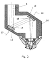
- a deflecting mirror 12 and a focusing mirror 13 are provided to direct the laser beam 6 to the workpiece.
- a gas jet coaxially with the laser beam 6, without the need for a transmissive element as a sealing element for pressure build-up.
- the two mirrors 12 and 13 are inserted in the direction of arrow 14 and 15 in recordings of a housing 16 .
- the two mirrors 12 and 13 are shown differently to illustrate their function. In reality, the mirrors 12 and 13 are formed almost identical and have only a different mirror surface 17 and 18, respectively.
- the example of the deflecting mirror 12 explains that the two mirrors have a mechanical coding for differentiation:
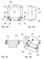
- the deflection mirror 12 is attached to a carrier 19 , which is inserted into the receptacle of the housing of the laser cutting head.
- the carrier 19 can be fastened to the housing via bores 20 .
- the carrier 19 additionally has threaded bores 21 to 24 , into which threaded pins 25 can be inserted and glued, so that the threaded pins protrude from the carrier 19 and protrude from its carrier surface 26 .
- the mechanical coding consists of the number and position of the set screws.
- the recording on the laser cutting head has according to the coding at least one recess for insertion of a threaded pin.
- One possible coding may be, for example, that set screws are inserted into the holes 21, 22 and 24 and three corresponding recesses are provided on the housing of the laser cutting head.
Landscapes
- Engineering & Computer Science (AREA)
- Physics & Mathematics (AREA)
- Optics & Photonics (AREA)
- Plasma & Fusion (AREA)
- Mechanical Engineering (AREA)
- Laser Beam Processing (AREA)
- Mounting And Adjusting Of Optical Elements (AREA)
Abstract
Description
- Die Erfindung betrifft ein optisches Element eines Laserbearbeitungskopfs.
- Spiegeloberflächen von nicht planen Spiegeln, wie Umlenkspiegel oder Fokussierspiegel eines Laserbearbeitungskopfs, können meistens visuell nicht unterschieden werden. Eindeutige Merkmale sind derzeit lediglich die Materialnummer oder eine Beschriftung. Diese Beschriftungen werden in einem separaten Arbeitsgang aufgebracht. Daher besteht eine erhebliche Verwechslungsgefahr. Zur optisch korrekten Funktion ist eine definierte Einbaulage und Orientierung des Spiegels notwendig. Trotz Beschriftung ist hier eine Fehlmontage möglich.
- Der Erfindung liegt die Aufgabe zugrunde, ein optisches Element eines Laserbearbeitungskopfs derart auszubilden und ein Einbauverfahren zu entwickeln, dass optische Elemente nur an ihrer Bestimmungsposition eingebaut werden können.
- Diese Aufgabe wird durch ein optisches Element mit einer mechanischen Kodierung zur Vorgabe des zulässigen Einbaus des optischen Elements in den Laserbearbeitungskopf gelöst. Die mechanische Kodierung führt zu einer eindeutigen Identifikation des optischen Elements. Der Einbauort des optischen Elements, wie eines Spiegels, am Laserbearbeitungskopf ist so beschaffen, dass nur das richtige optische Element in richtiger Einbaulage eingebaut werden kann. Werden beispielsweise Spiegel zur Reinigung ausgebaut oder Ersatzteile an den Kunden gesendet, so kann auch weniger qualifiziertes Personal die Komponenten ohne Verwechslungsgefahr handhaben.
- Neben der somit sichergestellten Funktion der optischen Anordnung ist auch die Zerstörung angrenzender Bauteile durch falsche optische Elemente ausgeschlossen. Beispielsweise würde ein Laserschneidkopfgehäuse durch den Einbau eines Spiegels mit zu langer Brennweite zerstört.
- Die mechanische Kodierung kann durch eine Profilierung an dem optischen Element ausgebildet sein. Dies können Zähne, Vorsprünge, eine Wölbung oder Erhöhung oder dergleichen sein, welche in eine entsprechende Vertiefung oder Ausnehmung des Laserbearbeitungskopfs einsetzbar sind. Es versteht sich, dass unter den Schutz der Erfindung auch die Umkehrung der Ausbildung von Profilierung und Vertiefung/Ausnehmung an dem optischen Element bzw. an dem Laserbearbeitungskopf fällt. Es bleibt von dem Schutz der Erfindung umfasst, wenn mindestens eine Profilierung ... und komplementär hierzu mindestens eine mit der Profilierung zusammenwirkende Ausnehmung ... ausgebildet sind.
- Bevorzugt ist es, dass das optische Element Gewindebohrungen aufweist, in die Gewindestifte einschraubbar ist. Diese Ausgestaltung ermöglicht es, die Kodierung zu wählen (Anzahl und Position der Stifte) und schnell umsetzen zu können.
- Wenn die Gewindestifte eingeklebt sind, ist die Kodierung dauerhaft ausgebildet.
- Die Erfindung ist für eine Vielzahl von Bauelementen eines Laserbearbeitungskopfs geeignet, insbesondere für Spiegel. Dieser kann zur Anbringung der Kodierung wie folgt ausgestaltet sein: Der Spiegel ist an einem Träger zur Befestigung am Gehäuse des Laserbearbeitungskopfs angebracht ist, welcher die mechanische Kodierung aufweist.
- Ein Ausführungsbeispiel der Erfindung ist in der Zeichnung schematisch dargestellt und wird nachfolgend mit Bezug zu den Figuren der Zeichnung näher erläutert. Es zeigt im Einzelnen:
- Fig. 1
- den Aufbau einer Laserschneidanlage;
- Fig. 2
- Teile des Laserschneidkopfs der Laserschneidanlage im Längsschnitt;
- Fig. 3a
- einen Spiegel des Laserschneidkopfs in der Draufsicht;
- Fig. 3b
- den Spiegel des Laserschneidkopfs in der Seitenansicht;
- Fig. 3c
- den Spiegel des Laserschneidkopfs gemäß einem Schnitt nach IIIc-IIIc in Fig. 3a;
- Fig. 3d
- den Spiegel des Laserschneidkopfs in perspektivischer Darstellung.
- Aus der Fig. 1 ist der Aufbau einer Laserbearbeitungsanlage 1 zum Laserschneiden mit einem CO2-Laser 2, einem Laserbearbeitungskopf 4 und einer Werkstückauflage 5 ersichtlich. Ein erzeugter Laserstrahl 6 wird mithilfe von Umlenkspiegeln zum Laserbearbeitungskopf 4 geführt und mithilfe von Spiegeln auf ein Werkstück 8 gerichtet.
- Bevor eine durchgängige Schnittfuge entsteht, muss der Laserstrahl 6 das Werkstück 8 durchdringen. Das Blech 8 muss an einer Stelle punktförmig geschmolzen oder oxidiert werden, und die Schmelze muss ausgeblasen werden. Der Einstechvorgang kann schnell (d.h. mit voller Laserleistung) oder langsam (über eine sog. "Rampe") erfolgen.
- Beim langsamen Einstechen mit einer Rampe kann die Laserleistung allmählich erhöht, reduziert und über einen bestimmten Zeitraum konstant gehalten werden, bis das Einstechloch erzeugt ist. Sowohl das Einstechen als auch das Laserschneiden werden durch Hinzufügen eines Gases unterstützt. Als Schneidgase 9 können Sauerstoff, Stickstoff, Druckluft und/oder anwendungsspezifische Gase eingesetzt werden. Welches Gas letztendlich verwendet wird, ist davon abhängig, welche Materialien geschnitten und welche Qualitätsansprüche an das Werkstück gestellt werden.
- Beim Schneiden mit Sauerstoff wird in der Regel mit einem Gasdruck von maximal 6 bar gearbeitet. Dort, wo der Laserstrahl 6 auf das Blech 8 auftrifft, wird das Material geschmolzen und zum größten Teil oxidiert. Die entstandene Schmelze wird zusammen mit den Eisenoxiden ausgeblasen. Entstehende Partikel und Gase können mithilfe einer Absaugeinrichtung 10 aus einer Absaugkammer 11 abgesaugt werden. Beim Oxidationsvorgang (exotherme Reaktion) wird zusätzlich Energie frei, die den Schneidprozess begünstig. In den Materialdicken, bei welchen für das Sauerstoffschneiden und das Stickstoff-Hochdruckschneiden dieselbe Laserleistung verwendet werden kann, ist es bei einer Verwendung von Sauerstoff als Schneidgas möglich, mit deutlich höheren Schneidgeschwindigkeiten zu arbeiten oder höhere Materialdicken zu trennen, als es beim Einsatz von Stickstoff der Fall wäre.
- Gemäß Fig. 2 sind ein Umlenkspiegel 12 und ein Fokussierspiegel 13 vorgesehen, um den Laserstrahl 6 auf das Werkstück zu richten. Mithilfe einer Ringspaltdüse ist es möglich, einen Gasstrahl koaxial zu dem Laserstrahl 6 zu erzeugen, ohne dass dafür ein transmissives Element als Dichtelement zum Druckaufbau benötigt wird. Die beiden Spiegel 12 und 13 werden in Pfeilrichtung 14 bzw. 15 in Aufnahmen eines Gehäuses 16 eingesetzt. In der Fig. 2 sind die beiden Spiegel 12 und 13 zur Verdeutlichung ihrer Funktion unterschiedlich dargestellt. In der Realität sind die Spiegel 12 und 13 nahezu identisch ausgebildet und weisen lediglich eine unterschiedliche Spiegeloberfläche 17 bzw. 18 auf.
- Am Beispiel des Umlenkspiegels 12 wird erläutert, dass die beiden Spiegel zur Unterscheidung eine mechanische Kodierung besitzen:
- Gemäß Fig. 3a bis Fig. 3d ist der Umlenkspiegel 12 an einem Träger 19 angebracht, welcher in die Aufnahme des Gehäuses des Laserschneidkopfs eingesetzt wird. Der Träger 19 kann über Bohrungen 20 an dem Gehäuse befestigt werden. Der Träger 19 weist zusätzlich Gewindebohrungen 21 bis 24 auf, in die Gewindestifte 25 eingesetzt und verklebt werden können, so dass die Gewindestifte aus dem Träger 19 herausragen und von dessen Trägeroberfläche 26 vorstehen. Die mechanische Kodierung besteht aus der Anzahl und Position der Gewindestifte. Die Aufnahme am Laserschneidkopf besitzt entsprechend der Kodierung mindestens eine Vertiefung zum Einführen eines Gewindestiftes. Eine mögliche Kodierung kann beispielsweise darin bestehen, dass Gewindestifte in die Bohrungen 21, 22 und 24 eingesetzt sind und drei entsprechende Vertiefungen am Gehäuse des Laserschneidkopfs vorhanden sind.
-
- 1
- Laserbearbeitungsanlage
- 2
- Laser
- 3
- 4
- Laserbearbeitungskopf
- 5
- Werkstückauflage
- 6
- Laserstrahl
- 7
- 8
- Werkstück
- 9
- Schneidgas
- 10
- Absaugeinrichtung
- 11
- Absaugkammer
- 12
- Umlenkspiegel
- 13
- Fokussierspiegel
- 14
- Einbaurichtung
- 15
- Einbaurichtung
- 16
- Gehäuse
- 17
- Spiegeloberfläche
- 18
- Spiegeloberfläche
- 19
- Träger
- 20
- Bohrung
- 21
- Gewindebohrung
- 22
- Gewindebohrung
- 23
- Gewindebohrung
- 24
- Gewindebohrung
- 25
- Gewindestift
- 26
- Trägeroberfläche
Claims (6)
- Optisches Element (12, 13) eines Laserbearbeitungskopfs (4), gekennzeichnet durch eine mechanische Kodierung zur Vorgabe des zulässigen Einbaus des optischen Elements (12, 13) in den Laserbearbeitungskopf (4).
- Optisches Element nach Anspruch 1, dadurch gekennzeichnet, dass die mechanische Kodierung durch eine Profilierung an dem optischen Element (12, 13) ausgebildet ist, welche in eine entsprechende Vertiefung oder Ausnehmung des Laserbearbeitungskopfs (4) einsetzbar ist.
- Optisches Element nach Anspruch 1 oder 2, dadurch gekennzeichnet, dass das optische Element (12, 13) Gewindebohrungen (21, 22, 23, 24) aufweist, in die Gewindestifte (25) einschraubbar ist.
- Optisches Element nach Anspruch 3, dadurch gekennzeichnet, dass die Gewindestifte (25) eingeklebt sind.
- Optisches Element nach einem der vorhergehenden Ansprüche, dadurch gekennzeichnet, dass das optische Element (12, 13) ein Spiegel ist.
- Optisches Element nach Anspruch 5, dadurch gekennzeichnet, dass der Spiegel (12) an einem Träger (19) zur Befestigung am Gehäuse (16) des Laserbearbeitungskopfs (4) angebracht ist, welcher die mechanische Kodierung aufweist.
Priority Applications (3)
| Application Number | Priority Date | Filing Date | Title |
|---|---|---|---|
| EP04024921A EP1649967B1 (de) | 2004-10-20 | 2004-10-20 | Optisches Element eines Laserbearbeitungskopfs |
| AT04024921T ATE519560T1 (de) | 2004-10-20 | 2004-10-20 | Optisches element eines laserbearbeitungskopfs |
| US11/255,072 US7947923B2 (en) | 2004-10-20 | 2005-10-20 | Encoded optical element of a laser processing head |
Applications Claiming Priority (1)
| Application Number | Priority Date | Filing Date | Title |
|---|---|---|---|
| EP04024921A EP1649967B1 (de) | 2004-10-20 | 2004-10-20 | Optisches Element eines Laserbearbeitungskopfs |
Publications (2)
| Publication Number | Publication Date |
|---|---|
| EP1649967A1 true EP1649967A1 (de) | 2006-04-26 |
| EP1649967B1 EP1649967B1 (de) | 2011-08-10 |
Family
ID=34927045
Family Applications (1)
| Application Number | Title | Priority Date | Filing Date |
|---|---|---|---|
| EP04024921A Expired - Lifetime EP1649967B1 (de) | 2004-10-20 | 2004-10-20 | Optisches Element eines Laserbearbeitungskopfs |
Country Status (3)
| Country | Link |
|---|---|
| US (1) | US7947923B2 (de) |
| EP (1) | EP1649967B1 (de) |
| AT (1) | ATE519560T1 (de) |
Families Citing this family (4)
| Publication number | Priority date | Publication date | Assignee | Title |
|---|---|---|---|---|
| US20070181544A1 (en) * | 2006-02-07 | 2007-08-09 | Universal Laser Systems, Inc. | Laser-based material processing systems and methods for using such systems |
| US8101883B2 (en) * | 2006-04-27 | 2012-01-24 | Universal Laser Systems, Inc. | Laser-based material processing systems and methods for using such systems |
| ATE515359T1 (de) * | 2006-04-28 | 2011-07-15 | Trumpf Werkzeugmaschinen Gmbh | Laserbearbeitungsverfahren |
| EP2117764B1 (de) * | 2007-02-13 | 2011-06-01 | Lasag Ag | Verfahren zum schneiden von zu verarbeitenden teilen mittels eines gepulsten lasers |
Citations (6)
| Publication number | Priority date | Publication date | Assignee | Title |
|---|---|---|---|---|
| US4772772A (en) * | 1986-07-11 | 1988-09-20 | Bias Forschungs und Entwicklungslabor fur Angewandte Strahtechnik GmbH | Process for the supervision of the machining process using a high-power energy source, in particular a laser, and machining optical system for carrying out the same |
| EP0974858A2 (de) * | 1998-07-22 | 2000-01-26 | Trumpf GmbH & Co | Lagerung für einen Spiegel zur Führung eines Laserstrahls an einer Laserbearbeitungsmaschine sowie Spiegelflächenträger als Teil einer derartigen Lagerung |
| US6166868A (en) * | 1997-08-18 | 2000-12-26 | Carl-Zeiss-Stiftung | Galvanoplastic optical mounting |
| EP1096415A1 (de) * | 1999-10-26 | 2001-05-02 | Datalogic S.P.A. | Optische Vorrichtung, Linse und optisches Element zum Fokussieren eines Laserstrahls, Verfahren und Vorrichtung zum Zusammenbau der optischen Vorrichtung |
| US20030095345A1 (en) | 2001-11-20 | 2003-05-22 | Canon Kabushiki Kaisha | Optical unit, exposure unit and optical devices |
| US20030123160A1 (en) | 2001-10-23 | 2003-07-03 | Thomas Zeller | Device for beam guiding a laser beam |
Family Cites Families (10)
| Publication number | Priority date | Publication date | Assignee | Title |
|---|---|---|---|---|
| IT1111412B (it) * | 1978-03-01 | 1986-01-13 | Prima Progetti Spa | Macchina automatica di taglio a raggio laser particolarmente per elementi di rivestimento interno di veicoli |
| JPS6032555B2 (ja) * | 1979-09-28 | 1985-07-29 | 株式会社日立製作所 | レ−ザビ−ム溶接回転ヘツド |
| CH645801A5 (fr) * | 1982-03-11 | 1984-10-31 | Lasag Ag | Tete optique d'une installation pour l'observation et le traitement par rayonnement laser de l'oeil. |
| IT1179776B (it) * | 1984-10-19 | 1987-09-16 | R T M Inst Per Le Ricerche Di | Testa di focalizzazione di un fascio laser |
| JPS6228094A (ja) * | 1985-07-30 | 1987-02-06 | Mitsubishi Electric Corp | レ−ザ加工機のレ−ザ光学装置 |
| JPH0275490A (ja) * | 1988-09-07 | 1990-03-15 | Fanuc Ltd | レーザビーム中継ユニット |
| JPH04322891A (ja) * | 1991-04-24 | 1992-11-12 | Brother Ind Ltd | レーザ加工装置 |
| US5249082A (en) * | 1991-05-08 | 1993-09-28 | Eastman Kodak Company | Exact constraint arrangement for and methods of mounting an element such as a lens |
| IT1320522B1 (it) * | 2000-07-04 | 2003-12-10 | Prima Ind Spa | Testa di focalizzazione per una macchina laser. |
| JP4095283B2 (ja) * | 2000-12-06 | 2008-06-04 | キヤノン株式会社 | レーザ装置 |
-
2004
- 2004-10-20 EP EP04024921A patent/EP1649967B1/de not_active Expired - Lifetime
- 2004-10-20 AT AT04024921T patent/ATE519560T1/de active
-
2005
- 2005-10-20 US US11/255,072 patent/US7947923B2/en active Active
Patent Citations (6)
| Publication number | Priority date | Publication date | Assignee | Title |
|---|---|---|---|---|
| US4772772A (en) * | 1986-07-11 | 1988-09-20 | Bias Forschungs und Entwicklungslabor fur Angewandte Strahtechnik GmbH | Process for the supervision of the machining process using a high-power energy source, in particular a laser, and machining optical system for carrying out the same |
| US6166868A (en) * | 1997-08-18 | 2000-12-26 | Carl-Zeiss-Stiftung | Galvanoplastic optical mounting |
| EP0974858A2 (de) * | 1998-07-22 | 2000-01-26 | Trumpf GmbH & Co | Lagerung für einen Spiegel zur Führung eines Laserstrahls an einer Laserbearbeitungsmaschine sowie Spiegelflächenträger als Teil einer derartigen Lagerung |
| EP1096415A1 (de) * | 1999-10-26 | 2001-05-02 | Datalogic S.P.A. | Optische Vorrichtung, Linse und optisches Element zum Fokussieren eines Laserstrahls, Verfahren und Vorrichtung zum Zusammenbau der optischen Vorrichtung |
| US20030123160A1 (en) | 2001-10-23 | 2003-07-03 | Thomas Zeller | Device for beam guiding a laser beam |
| US20030095345A1 (en) | 2001-11-20 | 2003-05-22 | Canon Kabushiki Kaisha | Optical unit, exposure unit and optical devices |
Also Published As
| Publication number | Publication date |
|---|---|
| EP1649967B1 (de) | 2011-08-10 |
| US20060081576A1 (en) | 2006-04-20 |
| US7947923B2 (en) | 2011-05-24 |
| ATE519560T1 (de) | 2011-08-15 |
Similar Documents
| Publication | Publication Date | Title |
|---|---|---|
| EP2108475A1 (de) | Vorrichtung und Verfahren zum automatischen Wechseln von Schneiddüsen | |
| EP0695607A1 (de) | Sägeblatt für eine Knochensäge und Knochensäge mit einem solchen Sägeblatt | |
| DE3722197A1 (de) | Verfahren zur kontrolle der position eines werkzeugtraegers in dem werkzeughalter einer werkzeugwechseleinrichtung sowie zur reinigung der kupplungsflaechen zwischen werkzeughalter und werkzeugtraeger und vorrichtung zur durchfuehrung dieses verfahrens | |
| WO2008141601A1 (de) | Anordnung zur erkennung einer laserbearbeitungsdüse beim einsetzen der laserbearbeitungsdüse in einen laserbearbeitungskopf | |
| EP1227426A1 (de) | Verfahren zum Anbringen eines maschinenlesbaren Datenträgers an einem Werkstück | |
| WO2019043039A1 (de) | Vorrichtung zum handhaben und/oder bearbeiten eines werkstücks sowie verfahren | |
| EP1649967B1 (de) | Optisches Element eines Laserbearbeitungskopfs | |
| DE2746232A1 (de) | Bohrstange zur metallbearbeitung | |
| DE202005021628U1 (de) | Optisches Element einer Laserbearbeitungsmaschine | |
| EP3189920B1 (de) | Fixiervorrichtung, drahterodiermaschine oder laseranlage und verfahren zum drahterodieren bzw. lasern | |
| EP3372331B1 (de) | Verfahren zum aufteilen eines plattenförmigen werkstücks | |
| EP1341652B1 (de) | Trenneinrichtung für unterwassergranulatoren | |
| EP0264599B1 (de) | Aufbohrwerkzeug | |
| EP2933075B1 (de) | Nachbearbeitungswerkzeug | |
| EP3684572B1 (de) | Verfahren zum bearbeiten von werkstücken, computerprogrammprodukt, sowie werkstückbearbeitungsanlage | |
| DE19854122A1 (de) | Verfahren und Anordnung zur Befestigung von Schneide-Elementen an einem Stammblatt eines beim Sägen verwendeten Sägeblattes | |
| WO2006131311A1 (de) | Vorrichtung zum herstellen von bohrungen, ausnehmungen, planflächen oder dergleichen | |
| EP0432637A1 (de) | Vorrichtung zum Nachschärfen der Schneidkante von Trennwerkzeugen beim Abtrennen von Scheiben von stab- oder blockförmigen Werkstücken, insbesondere aus Halbleitermaterial, ihre Verwendung und Sägeverfahren | |
| DE102012207643A1 (de) | Schneidevorrichtung zum Bearbeiten von faserverstärkten Kunststoffbauteilen | |
| DE20005348U1 (de) | Kreissägemaschine | |
| EP1677931B1 (de) | Vorrichtung zur spanabhebenden bearbeitung, verwendung dieser vorrichtung sowie verfahren zu dessem justage | |
| DE3412251A1 (de) | Messerhalterung fuer die messerwelle einer holzzerspanungsmaschine | |
| EP1790447B1 (de) | Verfahren und Vorrichtung zur Bearbeitung plattenförmiger Werkstücke | |
| EP2711117A1 (de) | Schneidvorrichtung mit einer Spritzschutzeinrichtung und Verfahren zum Schneiden von Werkstücken | |
| EP0645220A1 (de) | Anlage für Profilstahl/Flachstahl- und Blechbearbeitung |
Legal Events
| Date | Code | Title | Description |
|---|---|---|---|
| PUAI | Public reference made under article 153(3) epc to a published international application that has entered the european phase |
Free format text: ORIGINAL CODE: 0009012 |
|
| AK | Designated contracting states |
Kind code of ref document: A1 Designated state(s): AT BE BG CH CY CZ DE DK EE ES FI FR GB GR HU IE IT LI LU MC NL PL PT RO SE SI SK TR |
|
| AX | Request for extension of the european patent |
Extension state: AL HR LT LV MK |
|
| 17P | Request for examination filed |
Effective date: 20060906 |
|
| 17Q | First examination report despatched |
Effective date: 20061019 |
|
| AKX | Designation fees paid |
Designated state(s): AT BE BG CH CY CZ DE DK EE ES FI FR GB GR HU IE IT LI LU MC NL PL PT RO SE SI SK TR |
|
| GRAP | Despatch of communication of intention to grant a patent |
Free format text: ORIGINAL CODE: EPIDOSNIGR1 |
|
| GRAS | Grant fee paid |
Free format text: ORIGINAL CODE: EPIDOSNIGR3 |
|
| GRAA | (expected) grant |
Free format text: ORIGINAL CODE: 0009210 |
|
| AK | Designated contracting states |
Kind code of ref document: B1 Designated state(s): AT BE BG CH CY CZ DE DK EE ES FI FR GB GR HU IE IT LI LU MC NL PL PT RO SE SI SK TR |
|
| REG | Reference to a national code |
Ref country code: GB Ref legal event code: FG4D Free format text: NOT ENGLISH |
|
| REG | Reference to a national code |
Ref country code: CH Ref legal event code: EP |
|
| REG | Reference to a national code |
Ref country code: IE Ref legal event code: FG4D Free format text: LANGUAGE OF EP DOCUMENT: GERMAN |
|
| REG | Reference to a national code |
Ref country code: DE Ref legal event code: R096 Ref document number: 502004012775 Country of ref document: DE Effective date: 20111006 |
|
| REG | Reference to a national code |
Ref country code: NL Ref legal event code: VDEP Effective date: 20110810 |
|
| PG25 | Lapsed in a contracting state [announced via postgrant information from national office to epo] |
Ref country code: SE Free format text: LAPSE BECAUSE OF FAILURE TO SUBMIT A TRANSLATION OF THE DESCRIPTION OR TO PAY THE FEE WITHIN THE PRESCRIBED TIME-LIMIT Effective date: 20110810 Ref country code: NL Free format text: LAPSE BECAUSE OF FAILURE TO SUBMIT A TRANSLATION OF THE DESCRIPTION OR TO PAY THE FEE WITHIN THE PRESCRIBED TIME-LIMIT Effective date: 20110810 Ref country code: FI Free format text: LAPSE BECAUSE OF FAILURE TO SUBMIT A TRANSLATION OF THE DESCRIPTION OR TO PAY THE FEE WITHIN THE PRESCRIBED TIME-LIMIT Effective date: 20110810 Ref country code: PT Free format text: LAPSE BECAUSE OF FAILURE TO SUBMIT A TRANSLATION OF THE DESCRIPTION OR TO PAY THE FEE WITHIN THE PRESCRIBED TIME-LIMIT Effective date: 20111212 |
|
| PG25 | Lapsed in a contracting state [announced via postgrant information from national office to epo] |
Ref country code: CY Free format text: LAPSE BECAUSE OF FAILURE TO SUBMIT A TRANSLATION OF THE DESCRIPTION OR TO PAY THE FEE WITHIN THE PRESCRIBED TIME-LIMIT Effective date: 20110810 Ref country code: SI Free format text: LAPSE BECAUSE OF FAILURE TO SUBMIT A TRANSLATION OF THE DESCRIPTION OR TO PAY THE FEE WITHIN THE PRESCRIBED TIME-LIMIT Effective date: 20110810 Ref country code: GR Free format text: LAPSE BECAUSE OF FAILURE TO SUBMIT A TRANSLATION OF THE DESCRIPTION OR TO PAY THE FEE WITHIN THE PRESCRIBED TIME-LIMIT Effective date: 20111111 Ref country code: PL Free format text: LAPSE BECAUSE OF FAILURE TO SUBMIT A TRANSLATION OF THE DESCRIPTION OR TO PAY THE FEE WITHIN THE PRESCRIBED TIME-LIMIT Effective date: 20110810 |
|
| REG | Reference to a national code |
Ref country code: IE Ref legal event code: FD4D |
|
| BERE | Be: lapsed |
Owner name: TRUMPF WERKZEUGMASCHINEN G.M.B.H. + CO. KG Effective date: 20111031 |
|
| PG25 | Lapsed in a contracting state [announced via postgrant information from national office to epo] |
Ref country code: CZ Free format text: LAPSE BECAUSE OF FAILURE TO SUBMIT A TRANSLATION OF THE DESCRIPTION OR TO PAY THE FEE WITHIN THE PRESCRIBED TIME-LIMIT Effective date: 20110810 Ref country code: SK Free format text: LAPSE BECAUSE OF FAILURE TO SUBMIT A TRANSLATION OF THE DESCRIPTION OR TO PAY THE FEE WITHIN THE PRESCRIBED TIME-LIMIT Effective date: 20110810 Ref country code: IE Free format text: LAPSE BECAUSE OF FAILURE TO SUBMIT A TRANSLATION OF THE DESCRIPTION OR TO PAY THE FEE WITHIN THE PRESCRIBED TIME-LIMIT Effective date: 20110810 |
|
| PG25 | Lapsed in a contracting state [announced via postgrant information from national office to epo] |
Ref country code: RO Free format text: LAPSE BECAUSE OF FAILURE TO SUBMIT A TRANSLATION OF THE DESCRIPTION OR TO PAY THE FEE WITHIN THE PRESCRIBED TIME-LIMIT Effective date: 20110810 Ref country code: EE Free format text: LAPSE BECAUSE OF FAILURE TO SUBMIT A TRANSLATION OF THE DESCRIPTION OR TO PAY THE FEE WITHIN THE PRESCRIBED TIME-LIMIT Effective date: 20110810 Ref country code: MC Free format text: LAPSE BECAUSE OF NON-PAYMENT OF DUE FEES Effective date: 20111031 |
|
| PLBE | No opposition filed within time limit |
Free format text: ORIGINAL CODE: 0009261 |
|
| STAA | Information on the status of an ep patent application or granted ep patent |
Free format text: STATUS: NO OPPOSITION FILED WITHIN TIME LIMIT |
|
| PG25 | Lapsed in a contracting state [announced via postgrant information from national office to epo] |
Ref country code: DK Free format text: LAPSE BECAUSE OF FAILURE TO SUBMIT A TRANSLATION OF THE DESCRIPTION OR TO PAY THE FEE WITHIN THE PRESCRIBED TIME-LIMIT Effective date: 20110810 |
|
| 26N | No opposition filed |
Effective date: 20120511 |
|
| GBPC | Gb: european patent ceased through non-payment of renewal fee |
Effective date: 20111110 |
|
| PG25 | Lapsed in a contracting state [announced via postgrant information from national office to epo] |
Ref country code: BE Free format text: LAPSE BECAUSE OF NON-PAYMENT OF DUE FEES Effective date: 20111031 |
|
| REG | Reference to a national code |
Ref country code: DE Ref legal event code: R097 Ref document number: 502004012775 Country of ref document: DE Effective date: 20120511 |
|
| PG25 | Lapsed in a contracting state [announced via postgrant information from national office to epo] |
Ref country code: GB Free format text: LAPSE BECAUSE OF NON-PAYMENT OF DUE FEES Effective date: 20111110 |
|
| REG | Reference to a national code |
Ref country code: AT Ref legal event code: MM01 Ref document number: 519560 Country of ref document: AT Kind code of ref document: T Effective date: 20111020 |
|
| PG25 | Lapsed in a contracting state [announced via postgrant information from national office to epo] |
Ref country code: AT Free format text: LAPSE BECAUSE OF NON-PAYMENT OF DUE FEES Effective date: 20111020 |
|
| PG25 | Lapsed in a contracting state [announced via postgrant information from national office to epo] |
Ref country code: ES Free format text: LAPSE BECAUSE OF FAILURE TO SUBMIT A TRANSLATION OF THE DESCRIPTION OR TO PAY THE FEE WITHIN THE PRESCRIBED TIME-LIMIT Effective date: 20111121 |
|
| PG25 | Lapsed in a contracting state [announced via postgrant information from national office to epo] |
Ref country code: LU Free format text: LAPSE BECAUSE OF NON-PAYMENT OF DUE FEES Effective date: 20111020 |
|
| PG25 | Lapsed in a contracting state [announced via postgrant information from national office to epo] |
Ref country code: BG Free format text: LAPSE BECAUSE OF FAILURE TO SUBMIT A TRANSLATION OF THE DESCRIPTION OR TO PAY THE FEE WITHIN THE PRESCRIBED TIME-LIMIT Effective date: 20111110 |
|
| PG25 | Lapsed in a contracting state [announced via postgrant information from national office to epo] |
Ref country code: TR Free format text: LAPSE BECAUSE OF FAILURE TO SUBMIT A TRANSLATION OF THE DESCRIPTION OR TO PAY THE FEE WITHIN THE PRESCRIBED TIME-LIMIT Effective date: 20110810 |
|
| PG25 | Lapsed in a contracting state [announced via postgrant information from national office to epo] |
Ref country code: HU Free format text: LAPSE BECAUSE OF FAILURE TO SUBMIT A TRANSLATION OF THE DESCRIPTION OR TO PAY THE FEE WITHIN THE PRESCRIBED TIME-LIMIT Effective date: 20110810 |
|
| REG | Reference to a national code |
Ref country code: FR Ref legal event code: PLFP Year of fee payment: 12 |
|
| REG | Reference to a national code |
Ref country code: FR Ref legal event code: PLFP Year of fee payment: 13 |
|
| REG | Reference to a national code |
Ref country code: FR Ref legal event code: PLFP Year of fee payment: 14 |
|
| REG | Reference to a national code |
Ref country code: FR Ref legal event code: PLFP Year of fee payment: 15 |
|
| PGFP | Annual fee paid to national office [announced via postgrant information from national office to epo] |
Ref country code: DE Payment date: 20191021 Year of fee payment: 16 |
|
| PGFP | Annual fee paid to national office [announced via postgrant information from national office to epo] |
Ref country code: FR Payment date: 20191028 Year of fee payment: 16 Ref country code: IT Payment date: 20191028 Year of fee payment: 16 |
|
| PGFP | Annual fee paid to national office [announced via postgrant information from national office to epo] |
Ref country code: CH Payment date: 20191021 Year of fee payment: 16 |
|
| REG | Reference to a national code |
Ref country code: DE Ref legal event code: R119 Ref document number: 502004012775 Country of ref document: DE |
|
| REG | Reference to a national code |
Ref country code: CH Ref legal event code: PL |
|
| PG25 | Lapsed in a contracting state [announced via postgrant information from national office to epo] |
Ref country code: DE Free format text: LAPSE BECAUSE OF NON-PAYMENT OF DUE FEES Effective date: 20210501 Ref country code: FR Free format text: LAPSE BECAUSE OF NON-PAYMENT OF DUE FEES Effective date: 20201031 |
|
| PG25 | Lapsed in a contracting state [announced via postgrant information from national office to epo] |
Ref country code: CH Free format text: LAPSE BECAUSE OF NON-PAYMENT OF DUE FEES Effective date: 20201031 Ref country code: LI Free format text: LAPSE BECAUSE OF NON-PAYMENT OF DUE FEES Effective date: 20201031 |
|
| PG25 | Lapsed in a contracting state [announced via postgrant information from national office to epo] |
Ref country code: IT Free format text: LAPSE BECAUSE OF NON-PAYMENT OF DUE FEES Effective date: 20201020 |