EP1649160B1 - Soupape d'injection de carburant pour moteurs a combustion interne - Google Patents
Soupape d'injection de carburant pour moteurs a combustion interne Download PDFInfo
- Publication number
- EP1649160B1 EP1649160B1 EP04738091A EP04738091A EP1649160B1 EP 1649160 B1 EP1649160 B1 EP 1649160B1 EP 04738091 A EP04738091 A EP 04738091A EP 04738091 A EP04738091 A EP 04738091A EP 1649160 B1 EP1649160 B1 EP 1649160B1
- Authority
- EP
- European Patent Office
- Prior art keywords
- valve seat
- housing
- injection valve
- valve
- fuel injection
- Prior art date
- Legal status (The legal status is an assumption and is not a legal conclusion. Google has not performed a legal analysis and makes no representation as to the accuracy of the status listed.)
- Expired - Lifetime
Links
- 238000002347 injection Methods 0.000 title claims abstract description 97
- 239000007924 injection Substances 0.000 title claims abstract description 97
- 239000000446 fuel Substances 0.000 title claims description 56
- 238000002485 combustion reaction Methods 0.000 title claims description 8
- 238000000034 method Methods 0.000 claims abstract description 8
- 239000000463 material Substances 0.000 claims description 9
- 238000004519 manufacturing process Methods 0.000 claims description 4
- 238000003754 machining Methods 0.000 claims 1
- 238000007789 sealing Methods 0.000 abstract description 14
- 230000002950 deficient Effects 0.000 description 2
- 230000000694 effects Effects 0.000 description 2
- 238000003466 welding Methods 0.000 description 2
- 230000006835 compression Effects 0.000 description 1
- 238000007906 compression Methods 0.000 description 1
- 230000001419 dependent effect Effects 0.000 description 1
- 238000011161 development Methods 0.000 description 1
- 230000018109 developmental process Effects 0.000 description 1
- 239000002360 explosive Substances 0.000 description 1
- 239000012530 fluid Substances 0.000 description 1
- 230000013011 mating Effects 0.000 description 1
- 238000003860 storage Methods 0.000 description 1
- 238000011144 upstream manufacturing Methods 0.000 description 1
Images


Classifications
-
- F—MECHANICAL ENGINEERING; LIGHTING; HEATING; WEAPONS; BLASTING
- F02—COMBUSTION ENGINES; HOT-GAS OR COMBUSTION-PRODUCT ENGINE PLANTS
- F02M—SUPPLYING COMBUSTION ENGINES IN GENERAL WITH COMBUSTIBLE MIXTURES OR CONSTITUENTS THEREOF
- F02M61/00—Fuel-injectors not provided for in groups F02M39/00 - F02M57/00 or F02M67/00
- F02M61/16—Details not provided for in, or of interest apart from, the apparatus of groups F02M61/02 - F02M61/14
- F02M61/18—Injection nozzles, e.g. having valve seats; Details of valve member seated ends, not otherwise provided for
- F02M61/188—Spherical or partly spherical shaped valve member ends
-
- F—MECHANICAL ENGINEERING; LIGHTING; HEATING; WEAPONS; BLASTING
- F02—COMBUSTION ENGINES; HOT-GAS OR COMBUSTION-PRODUCT ENGINE PLANTS
- F02M—SUPPLYING COMBUSTION ENGINES IN GENERAL WITH COMBUSTIBLE MIXTURES OR CONSTITUENTS THEREOF
- F02M61/00—Fuel-injectors not provided for in groups F02M39/00 - F02M57/00 or F02M67/00
- F02M61/04—Fuel-injectors not provided for in groups F02M39/00 - F02M57/00 or F02M67/00 having valves, e.g. having a plurality of valves in series
- F02M61/10—Other injectors with elongated valve bodies, i.e. of needle-valve type
-
- F—MECHANICAL ENGINEERING; LIGHTING; HEATING; WEAPONS; BLASTING
- F02—COMBUSTION ENGINES; HOT-GAS OR COMBUSTION-PRODUCT ENGINE PLANTS
- F02M—SUPPLYING COMBUSTION ENGINES IN GENERAL WITH COMBUSTIBLE MIXTURES OR CONSTITUENTS THEREOF
- F02M61/00—Fuel-injectors not provided for in groups F02M39/00 - F02M57/00 or F02M67/00
- F02M61/16—Details not provided for in, or of interest apart from, the apparatus of groups F02M61/02 - F02M61/14
- F02M61/18—Injection nozzles, e.g. having valve seats; Details of valve member seated ends, not otherwise provided for
-
- F—MECHANICAL ENGINEERING; LIGHTING; HEATING; WEAPONS; BLASTING
- F02—COMBUSTION ENGINES; HOT-GAS OR COMBUSTION-PRODUCT ENGINE PLANTS
- F02M—SUPPLYING COMBUSTION ENGINES IN GENERAL WITH COMBUSTIBLE MIXTURES OR CONSTITUENTS THEREOF
- F02M63/00—Other fuel-injection apparatus having pertinent characteristics not provided for in groups F02M39/00 - F02M57/00 or F02M67/00; Details, component parts, or accessories of fuel-injection apparatus, not provided for in, or of interest apart from, the apparatus of groups F02M39/00 - F02M61/00 or F02M67/00; Combination of fuel pump with other devices, e.g. lubricating oil pump
- F02M63/02—Fuel-injection apparatus having several injectors fed by a common pumping element, or having several pumping elements feeding a common injector; Fuel-injection apparatus having provisions for cutting-out pumps, pumping elements, or injectors; Fuel-injection apparatus having provisions for variably interconnecting pumping elements and injectors alternatively
- F02M63/0205—Fuel-injection apparatus having several injectors fed by a common pumping element, or having several pumping elements feeding a common injector; Fuel-injection apparatus having provisions for cutting-out pumps, pumping elements, or injectors; Fuel-injection apparatus having provisions for variably interconnecting pumping elements and injectors alternatively for cutting-out pumps or injectors in case of abnormal operation of the engine or the injection apparatus, e.g. over-speed, break-down of fuel pumps or injectors ; for cutting-out pumps for stopping the engine
- F02M63/0215—Fuel-injection apparatus having several injectors fed by a common pumping element, or having several pumping elements feeding a common injector; Fuel-injection apparatus having provisions for cutting-out pumps, pumping elements, or injectors; Fuel-injection apparatus having provisions for variably interconnecting pumping elements and injectors alternatively for cutting-out pumps or injectors in case of abnormal operation of the engine or the injection apparatus, e.g. over-speed, break-down of fuel pumps or injectors ; for cutting-out pumps for stopping the engine by draining or closing fuel conduits
-
- F—MECHANICAL ENGINEERING; LIGHTING; HEATING; WEAPONS; BLASTING
- F02—COMBUSTION ENGINES; HOT-GAS OR COMBUSTION-PRODUCT ENGINE PLANTS
- F02M—SUPPLYING COMBUSTION ENGINES IN GENERAL WITH COMBUSTIBLE MIXTURES OR CONSTITUENTS THEREOF
- F02M2200/00—Details of fuel-injection apparatus, not otherwise provided for
- F02M2200/90—Selection of particular materials
- F02M2200/9053—Metals
-
- F—MECHANICAL ENGINEERING; LIGHTING; HEATING; WEAPONS; BLASTING
- F02—COMBUSTION ENGINES; HOT-GAS OR COMBUSTION-PRODUCT ENGINE PLANTS
- F02M—SUPPLYING COMBUSTION ENGINES IN GENERAL WITH COMBUSTIBLE MIXTURES OR CONSTITUENTS THEREOF
- F02M47/00—Fuel-injection apparatus operated cyclically with fuel-injection valves actuated by fluid pressure
- F02M47/02—Fuel-injection apparatus operated cyclically with fuel-injection valves actuated by fluid pressure of accumulator-injector type, i.e. having fuel pressure of accumulator tending to open, and fuel pressure in other chamber tending to close, injection valves and having means for periodically releasing that closing pressure
- F02M47/027—Electrically actuated valves draining the chamber to release the closing pressure
-
- F—MECHANICAL ENGINEERING; LIGHTING; HEATING; WEAPONS; BLASTING
- F02—COMBUSTION ENGINES; HOT-GAS OR COMBUSTION-PRODUCT ENGINE PLANTS
- F02M—SUPPLYING COMBUSTION ENGINES IN GENERAL WITH COMBUSTIBLE MIXTURES OR CONSTITUENTS THEREOF
- F02M61/00—Fuel-injectors not provided for in groups F02M39/00 - F02M57/00 or F02M67/00
- F02M61/04—Fuel-injectors not provided for in groups F02M39/00 - F02M57/00 or F02M67/00 having valves, e.g. having a plurality of valves in series
- F02M61/10—Other injectors with elongated valve bodies, i.e. of needle-valve type
- F02M61/12—Other injectors with elongated valve bodies, i.e. of needle-valve type characterised by the provision of guiding or centring means for valve bodies
-
- F—MECHANICAL ENGINEERING; LIGHTING; HEATING; WEAPONS; BLASTING
- F02—COMBUSTION ENGINES; HOT-GAS OR COMBUSTION-PRODUCT ENGINE PLANTS
- F02M—SUPPLYING COMBUSTION ENGINES IN GENERAL WITH COMBUSTIBLE MIXTURES OR CONSTITUENTS THEREOF
- F02M61/00—Fuel-injectors not provided for in groups F02M39/00 - F02M57/00 or F02M67/00
- F02M61/16—Details not provided for in, or of interest apart from, the apparatus of groups F02M61/02 - F02M61/14
- F02M61/166—Selection of particular materials
-
- F—MECHANICAL ENGINEERING; LIGHTING; HEATING; WEAPONS; BLASTING
- F02—COMBUSTION ENGINES; HOT-GAS OR COMBUSTION-PRODUCT ENGINE PLANTS
- F02M—SUPPLYING COMBUSTION ENGINES IN GENERAL WITH COMBUSTIBLE MIXTURES OR CONSTITUENTS THEREOF
- F02M61/00—Fuel-injectors not provided for in groups F02M39/00 - F02M57/00 or F02M67/00
- F02M61/16—Details not provided for in, or of interest apart from, the apparatus of groups F02M61/02 - F02M61/14
- F02M61/168—Assembling; Disassembling; Manufacturing; Adjusting
Definitions
- the present invention relates to a fuel injection valve for intermittent fuel injection in the combustion chamber of internal combustion engines according to the preamble of claim 1 and a method for its production.
- valve seat member is formed as a nozzle body separate from the valve housing, which is provided with the injection openings and the valve seat for the injection valve member.
- This nozzle body is attached by means of a welded connection to the housing. Since the nozzle body consists of a different, usually more wear-resistant material than the housing, problems may arise due to the different material properties during welding. In addition, the welding connection is stressed very heavily on the one hand by the high system pressure prevailing in the fuel injection valve and on the other hand by the impact of the injection valve member on the nozzle body when closing. Therefore, very high demands must be placed on the quality of the welded joint.
- the injection valve member of the mentioned in WO-A-02/086309 described fuel injectors is at its the valve seat or nozzle body end facing also strong mechanical stresses mentioned, for the same reasons as mentioned above in connection with the valve seat member or the nozzle body. This is especially true when the nozzle body is made of a more wear-resistant material than the injection valve member.
- valve seat part is connected by means of a clamping nut directly or indirectly with the housing ( DE-A-19 944 878 ; GB-C-885,627 ; EP-A-0 961 025 ).
- valve seat member is formed as a separate component from the housing.
- connection of the valve seat part with the housing takes place in different ways by means of further, belonging to the fuel injection valve components.
- the present invention is based on the object to be able to connect the valve seat part in a fuel injection valve of the type mentioned in a simple and reliable way with the housing.
- valve seat part The provided on its outer side with a conical seat, acted upon by the fuel high pressure in the high-pressure chamber valve seat part is located on the formed on the housing, also tapered bearing surface. Because of the self-locking design of this seat and bearing surface of the valve seat part is firmly and sealingly held in the housing, without the need for additional clamping or fastening means are needed.
- the method for producing the fuel injection valve according to the invention is characterized by the features of claim 6. With this method, the fuel injection valve according to the invention can be produced in the simplest and most cost-effective manner possible.
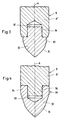
- FIG. 1 schematically illustrated fuel injector 1, of which only the lower part is shown, has a housing 2, which is formed by an upper housing part, not shown, a lower housing part 2a and a valve seat member 2b.
- the valve seat element 2 b is tightly connected to the lower housing part 2 a by means of a holding element 3 designed as a clamping nut.
- valve seat part 4 is held, which is formed as a nozzle body 4 a separate from the valve seat member 2 b and has a valve seat 5 and injection openings 6.
- a central, coaxial to the longitudinal axis A of the housing 2 bore 7 is formed over its length changing diameter defining a high-pressure chamber 8.
- This high-pressure chamber 8 communicates with a high-pressure fuel inlet in a manner not shown, and extends as far as the valve seat 5.
- a coaxial injection valve member 9 is arranged, which in the in the FIG. 1 shown closing position with its tip 9a with the valve seat 5 cooperates to close the injection openings 6.
- the injection valve member 9 is lifted off the valve seat 5 by means of a control device, not shown.
- the injection valve member 9 is guided with a guide member 9b by means of a close sliding fit in the valve seat member 2b.
- the guide part 9b is provided with grinding surfaces 10.
- the injection valve member 9 is pressed by means of a closing spring 11 in the closing direction of the injection valve member 9 down.
- the closing spring 11 relies on her in the FIG. 1 shown end on a support ring 12 which rests on a shoulder 13 on the injection valve member 9. At the other end, not shown, the closing spring 11 is fixed to the housing.
- the fuel injection valve 1 according to FIG. 1 a arranged in the interior of the high-pressure chamber 8 flow rate limiting valve 14.
- To flow rate limiting valve 14 includes a housing longitudinal axis A coaxial valve body 15 which is housed in a valve chamber 16 which forms part of the high-pressure chamber 8.
- the valve body 15 has a U-shaped cross section and consists of a cylindrical bottom portion 15 a and a bottom portion 15 a coaxial annular portion 15 b, which is open to the valve seat 5 out.
- the valve body 15 is guided with its bottom part 15a through a guide portion 9c of the injection valve member 9 with a tight sliding fit.
- the bottom part 15a is acted upon by the pressure prevailing in the high-pressure chamber 8 fuel pressure.
- annular gap 18 is formed, whose width is preferably 0.03 - 0.2 mm.
- the valve body 15 is adjustable between an open position (upper end position) and a closed position (lower end position). In the open position, the valve body 15 rests with its end face 19 on an annular stop face 20, which is formed in the lower housing part 2a. At this end face 19 opposite end of the valve body 15 is provided with a conical sealing surface 21 which cooperates in the closed position of the valve body 15 with a likewise conical seat surface 22 in the valve seat member 2b. Both the sealing surface 21 and the seat surface 22 are formed by sections of lateral surfaces of circular cones, which have approximately the same opening angle.
- the sealing surface 21 and the seat surface 22 may also be formed as flat surfaces which extend at right angles to the housing longitudinal axis A.
- the valve body 15 is loaded by an acting in the opening direction, designed as a compression spring spring element 23.
- This spring element 23 extends in the interior of the annular part 15b and is supported on the bottom part 15a of the valve body 15. At the other end, the spring element 23 is supported on a support surface 24, which is formed in the valve seat element 2b.
- the operation of the flow rate limiting valve 14 is similar to that in the DE-A-43 44 190 described operation of the check valves shown there.
- the valve body 15 assumes its open position in the normal operating state between the injection events. If the injection openings 6 are released during an injection process by lifting off the injection valve member 9 from the valve seat 5, a pressure drop occurs on the injection side which effects a movement of the valve body 15 acted upon at its end face 19 against the force of the spring element 23 from the open position against the closed position , However, the valve body 15 does not move into its closed position. At the end of the injection process by closing the injection openings 6 through the injection valve member. 9 comes the valve body 15 in an intermediate position between its open position and its closed position to a stop. In this intermediate position, fuel flows via the annular gap 18. Due to the again increasing pressure on the valve seat part 4 facing side of the valve body 15 and under the action of the spring element 23, the valve body 15 moves back to its open position.
- both the sealing surface 21 on the valve body 15 and the seat surface 22 on the valve seat element 2b are formed as sections of lateral surfaces of circular cones whose opening angles are designed such that a self-locking effect occurs when the valve body 15 is in the closed position.
- these circular cones have a half opening angle of 2 ° - 7 °.
- the annular part 15b of the valve body 15 has a relatively large wall thickness. Now, the valve body 15 is in its closed position and prevails in the high-pressure chamber 8 upstream of the seat surface 22, i. So also in the annular gap 18, the fuel high pressure (for example, 2000 bar and more), the annular part 15b is pressed together in the radial direction. If the feed pressure drops, the annular part 15b widens again, which results in jamming of the valve body 15 on the conical seat surface 22.
- An engine having a fuel injection valve 1 with an integrated flow rate limiting valve 14 can thus be stopped and restarted without a defective fuel injection valve 1 leading to an engine overload.
- the engine thus has emergency running properties even after a stop.
- the annular gap 18 forms a fuel flow connection in the intermediate positions of the valve body 15.
- Such can also be done in other ways, for example by at least one, extending in the direction of the housing longitudinal axis A longitudinal groove the outside of the valve body 15 or in the wall 16a of the valve chamber.
- the valve body 15 may also have a cross-sectional shape other than that shown, and may have a T-shaped cross-section, for example.
- a cross-sectional shape of the adjoining the bottom part 15a annular part - unlike as in FIG. 1 shown - a smaller diameter than the bottom part 15 a and is the same as the bottom part 15 a guided by the guide portion 9 c of the injection valve member 9.
- the valve body 15 has a both the bottom part 15a as well as the annular part passing through guide bore through which the injection valve member 9 extends with a close sliding fit.
- the spring element 23 which is supported on the bottom part 15a and on the support surface 24 then surrounds the annular part.
- the above-mentioned fuel flow connection can also be formed in this embodiment of the valve body 15 through a passage in the valve body 15 itself.
- the passage of leakage fluid is prevented by the close sliding fit, because the annular part of the valve body 15 in the closed position of the valve body 15, both under the high pressure acting on its cylindrical outer surface, as well as by the force acting in the radial direction deforms the mating conical surfaces 21 and 22 and presses against the injection valve member 9.
- the valve body 15 can be formed with a smaller diameter, so that the wall thickness of the lower housing part 2a can be larger and the wall pressure-resistant.
- valve seat member 4 held in the valve seat member 2b is one of the valve seat member 2b separate nozzle body 4a formed.
- FIG. 2 which shows the injection-side end of the fuel injection valve 1 in an enlarged scale, will now be explained in more detail the manner in which this valve seat part 4 or nozzle body 4a is held in the valve seat element 2b.
- the nozzle body 4a is made of a substantially harder material than the housing 2 of the fuel injection valve 1, to reduce the wear smaller and thus to extend the life of the fuel injection valve 1. Since the material used to make the nozzle body 4a is very expensive, the nozzle body 4a is made very small for reasons of cost.
- the nozzle body 4a has on its outer side a conical seat surface 26, which is formed by a portion of the lateral surface of a straight circular cone whose axis coincides with the housing longitudinal axis A. With this seat surface 26 of the nozzle body 4a abuts against a likewise tapered bearing surface 27, which is formed in the valve seat member 2b. This support surface 27 is also formed by a portion of the lateral surface of a straight circular cone whose axis coincides with the housing longitudinal axis A.
- the half opening angle 28 of both the seat surface 26 and the bearing surface 27 forming circular cone are chosen such that the nozzle body 4a is held self-locking and sealing in the valve seat member 2b. These half opening angle 28 are 2 ° - 7 °.
- FIG. 2 is used during assembly of the nozzle body 4a from above into the valve seat member 2b.
- both the valve seat 5 and the seat surface 26 are formed by grinding in the same clamping of the nozzle body 4a.
- a guide surface 2 'for guiding the guide part 9b of the injection valve member 9 and the bearing surface 27 are ground on the valve seat element 2b in the same clamping of the valve seat element 2b.
- the grinding tool (grinding mandrel) is preferably inserted into the valve seat element 2b from the side of the bearing surface 27.
- fuel injector 1 is the seat surface 22 in the lower housing part 2a.
- the valve body 15 is installed in the housing 2 from above.
- the stop surface 20 and the holding element 3 omitted.
- a stop element can be installed, for example an explosive or circlip (Seeger ring or the like).
- the end face 19 of the valve body 15 could be supported on the underside of the support ring 12. Then, the force of the spring element 23 would be passed up to the support ring 12 on. As a result, the force of the closing spring 11 acting in the closing direction of the injection valve member 9 would be reduced before the start of an injection process, which may be advantageous in certain cases.
- the housing part 2a and the valve seat element 2b can also be made in one piece and form part of the housing 2.
- the clamping nut 3 can be omitted as mentioned. In this case, the processing of the guide surface 2 'and the support surface 27 from the side of the support surface 27 ago particularly advantageous.
- the described embodiment of the nozzle body 4a according to the invention is also possible with fuel injection valves, in which the fuel supply to the valve seat 5 via a relative to the housing longitudinal axis A laterally offset feed channel (instead of as shown via the central high-pressure chamber 8).
- valve seat member 4 formed as a separate nozzle body 4a is made of a more wear-resistant (harder) material than the housing 2, which brings about an extension of the life of the valve seat member 4.
- FIGS. 2 to 5 Now embodiments of fuel injection valves 1 are shown, in which the life of the injection valve member 9 is extended.
- the tip 9a of the injection valve member 9 is formed by an insert part 30 which is connected or coupled to the adjacent section 9 'of the injection valve member 9 for joint movement and has a sealing surface 31 coming into contact with the conical valve seat 5.
- the insert 30 is made of a harder, more wear-resistant, but also more expensive material than the rest of the injection valve member 9. It is therefore desirable to keep this insert 30 as small as possible.
- the insert part 30 has a cylindrical shape and engages in an opening 32 in the adjacent section 9 'of the injection valve member 9 a. So that the insert 30 can be replaced if necessary, it is held with a press fit in the opening 32.
- the insert 30 When in the FIG. 3 As shown variant of the insert 30 has smaller dimensions than the insert 30 according to FIG. 2 and has a sealing body 33 and a smaller diameter holding member 34 which is integral with the sealing body 33.
- the sealing body 33 is provided with the sealing surface 31 and projects beyond the adjacent region 9 'of the injection valve member 9, while the holding member 34 engages in the opening 32 in this adjacent portion 9' of the injection valve member 9 and is held in this with a press fit.
- FIG. 5 schematically the lower part of a third embodiment of a fuel injection valve 1 is shown, wherein in this FIG. 5 for those parts that are in the FIGS. 1 and 2 shown embodiments, the same reference numerals are used as in the FIGS. 1 and 2 ,
- valve seat part 4 is held in the housing 2.
- the valve seat part 4 at its opposite end of the valve seat 5 on its outer side a conical seat 43, which is formed by a portion of the lateral surface of a straight circular cone whose axis coincides with the housing longitudinal axis A.
- This seat surface 43 of the valve seat part 4 abuts against a likewise conical bearing surface 44, which is formed in the housing 2.
- This support surface 44 is also formed by a portion of the lateral surface of a straight circular cone whose axis coincides with the housing longitudinal axis A.
- the half opening angle 45 of the two seat 43 and the support surface 44 forming circular cone are chosen such that the valve seat member 4 is held self-locking and sealing in the housing 2. These half opening angle 45 are 2 ° - 7 °.
- valve seat part 4 the same as the nozzle body 4a of the embodiments according to the FIGS. 1 and 2 , made of a material substantially harder than the housing 2 of the fuel injection valve 1 in order to reduce the wear smaller and thus extend the life of the fuel injection valve 1.
- valve seat part 4 is inserted from above into the housing 2.
- the valve seat part 4 is formed as an elongate member and has an outer diameter which is smaller than the outer diameter of the housing 2. In the embodiment according to Fig. 5 Therefore, the outer diameter of the lower end of the fuel injection valve 1 is smaller than in the embodiment according to the Fig. 1 and 2 ,
- the injection valve member 9 is guided in the valve seat part 4. Accordingly, the wall 46 of the inner bore 47 of the valve seat part 4 is formed as a guide surface for the guide part 9b of the injection valve member 9.
Landscapes
- Engineering & Computer Science (AREA)
- Chemical & Material Sciences (AREA)
- Combustion & Propulsion (AREA)
- Mechanical Engineering (AREA)
- General Engineering & Computer Science (AREA)
- Fuel-Injection Apparatus (AREA)
Claims (7)
- Soupape d'injection de carburant pour l'injection intermittente de carburant dans la chambre de combustion de moteurs à combustion interne, comprenant un boîtier oblong (2), une partie de siège de soupape (4), qui présente un siège de soupape (5) pourvu d'ouvertures d'injection (6), un espace haute pression (8) disposé à l'intérieur du boîtier (2), en liaison avec une entrée de carburant haute pression, qui s'étend jusqu'au siège de soupape (5), un organe de soupape d'injection (9) réglable en longueur et disposé dans le boîtier (2), qui coopère avec le siège de soupape (5) pour la fermeture et l'ouverture des ouvertures d'injection (6), et un dispositif de commande pour commander le mouvement de réglage de l'organe de soupape d'injection (9), caractérisée en ce que la partie de siège de soupape (4) est pourvue sur son côté extérieur d'une surface de siège (26 ; 43) formée à travers la surface d'enveloppe d'un cône circulaire, avec laquelle elle s'applique contre une surface d'appui (27 ; 44) sur le boîtier (2), formée également par la surface d'enveloppe d'un cône circulaire, les demi-angles d'ouverture (28 ; 45) du cône circulaire définissant la surface de siège (26 ; 43) et la surface d'appui (27 ; 44) étant choisis de telle sorte que la partie de siège de soupape (4) soit maintenue de manière autobloquante et hermétique dans le boîtier (2).
- Soupape d'injection de carburant selon la revendication 1, caractérisée en ce que les demi-angles d'ouverture de préférence approximativement égaux (28 ; 45) valent 2° à 7°.
- Soupape d'injection de carburant selon la revendication 1, caractérisée en ce que l'organe de soupape d'injection (9) est disposé dans l'espace haute pression (8) s'étendant coaxialement par rapport à l'axe longitudinal (A) du boîtier (2).
- Soupape d'injection de carburant selon l'une quelconque des revendications 1 à 3, caractérisée en ce que la partie de siège de soupape allongée (4) présente un alésage interne (47) dont la paroi (46) est réalisée en tant que guide pour l'organe de soupape d'injection (9).
- Soupape d'injection de carburant selon l'une quelconque des revendications 1 à 4, caractérisée en ce que la partie de siège de soupape (4) se compose d'un matériau plus résistant à l'usure que le boîtier (2).
- Procédé de fabrication de la soupape d'injection de carburant selon l'une quelconque des revendications 1 à 5, caractérisé en ce que dans la même étendue du boîtier (2) sont réalisées, sur ce dernier, à la fois la surface d'appui (27) et une surface de guidage (2') pour l'organe de soupape d'injection (9).
- Procédé selon la revendication 6, caractérisé en ce que l'usinage de la surface d'appui (27) et de la surface de guidage (2') a lieu au moyen d'un outil qui est introduit depuis le côté ayant la surface d'appui (27) dans le boîtier (2).
Applications Claiming Priority (2)
| Application Number | Priority Date | Filing Date | Title |
|---|---|---|---|
| CH12482003 | 2003-07-17 | ||
| PCT/CH2004/000451 WO2005008059A1 (fr) | 2003-07-17 | 2004-07-14 | Soupape d'injection de carburant pour moteurs a combustion interne |
Publications (2)
| Publication Number | Publication Date |
|---|---|
| EP1649160A1 EP1649160A1 (fr) | 2006-04-26 |
| EP1649160B1 true EP1649160B1 (fr) | 2009-08-19 |
Family
ID=34069953
Family Applications (1)
| Application Number | Title | Priority Date | Filing Date |
|---|---|---|---|
| EP04738091A Expired - Lifetime EP1649160B1 (fr) | 2003-07-17 | 2004-07-14 | Soupape d'injection de carburant pour moteurs a combustion interne |
Country Status (6)
| Country | Link |
|---|---|
| US (1) | US20060113406A1 (fr) |
| EP (1) | EP1649160B1 (fr) |
| KR (1) | KR20060030116A (fr) |
| AT (1) | ATE440216T1 (fr) |
| DE (1) | DE502004009930D1 (fr) |
| WO (1) | WO2005008059A1 (fr) |
Families Citing this family (12)
| Publication number | Priority date | Publication date | Assignee | Title |
|---|---|---|---|---|
| DE102007008863A1 (de) * | 2005-08-26 | 2008-08-28 | Robert Bosch Gmbh | Brennstoffeinspritzventil |
| DE102005061424A1 (de) * | 2005-12-22 | 2007-07-05 | Robert Bosch Gmbh | Brennstoffeinspritzventil |
| CN101542103B (zh) | 2006-10-16 | 2011-12-14 | 甘瑟-许德罗玛格股份公司 | 内燃机的燃油喷射阀 |
| EP3252302B1 (fr) * | 2015-01-30 | 2019-10-30 | Hitachi Automotive Systems, Ltd. | Robinet d'injection de carburant |
| CN110402288A (zh) | 2017-02-16 | 2019-11-01 | 斯威特沃特能源公司 | 用于预处理的高压区形成 |
| WO2019206895A1 (fr) * | 2018-04-25 | 2019-10-31 | Robert Bosch Gmbh | Ensemble siège de soupape d'injecteur de carburant comprenant des éléments de positionnement et de retenue d'insert |
| JP2021521378A (ja) * | 2018-04-25 | 2021-08-26 | ロベルト・ボッシュ・ゲゼルシャフト・ミト・ベシュレンクテル・ハフツングRobert Bosch Gmbh | 所定箇所に形成されたインサートを含む燃料噴射器バルブシートアセンブリとその製造方法 |
| JP7157820B2 (ja) * | 2018-04-25 | 2022-10-20 | ロベルト・ボッシュ・ゲゼルシャフト・ミト・ベシュレンクテル・ハフツング | バルブシートを形成するインサートを含む燃料噴射器バルブシートアセンブリ |
| WO2019206898A1 (fr) * | 2018-04-25 | 2019-10-31 | Robert Bosch Gmbh | Ensemble siège de soupape d'injecteur de carburant comprenant un insert ayant des fonctions anticalaminage |
| DE102019103329A1 (de) * | 2019-02-11 | 2020-08-13 | Liebherr-Components Deggendorf Gmbh | Düse eines Kraftstoffinjektors und Kraftstoffinjektor mit einer solchen Düse |
| WO2021133733A1 (fr) | 2019-12-22 | 2021-07-01 | Sweetwater Energy, Inc. | Procédés de fabrication de lignine et de produits de lignine spécialisés à partir de biomasse |
| IL301784A (en) * | 2020-10-02 | 2023-05-01 | Sweetwater Energy Inc | Pressure valve machining |
Family Cites Families (11)
| Publication number | Priority date | Publication date | Assignee | Title |
|---|---|---|---|---|
| GB885627A (en) * | 1959-09-15 | 1961-12-28 | Goetaverken Ab | Improvements in fuel injection valves for internal combustion engines |
| GB1565210A (en) * | 1975-10-21 | 1980-04-16 | Lucas Industries Ltd | Fuel injection nozzles for direct injection internal combustion engine |
| US4544096A (en) * | 1983-07-28 | 1985-10-01 | Energy Conservation Innovations, Inc. | Electronically controlled fuel injection system for diesel engine |
| FR2558533B1 (fr) * | 1984-01-23 | 1986-06-13 | Renault | Dispositif de securite pour soupape d'injection de moteur a combustion interne |
| US5409165A (en) * | 1993-03-19 | 1995-04-25 | Cummins Engine Company, Inc. | Wear resistant fuel injector plunger assembly |
| DK171975B1 (da) * | 1994-02-07 | 1997-09-01 | Man B & W Diesel Gmbh | Brændselsinjektor til en stor totakts forbrændingsmotor |
| EP0961025A1 (fr) * | 1998-05-29 | 1999-12-01 | Wärtsilä NSD Schweiz AG | Buse d'injection de combustible |
| DE19944878A1 (de) * | 1999-09-18 | 2001-03-22 | Volkswagen Ag | Kraftstoffeinspritzventil für Brennkraftmaschinen |
| US6279843B1 (en) * | 2000-03-21 | 2001-08-28 | Caterpillar Inc. | Single pole solenoid assembly and fuel injector using same |
| DE10024661A1 (de) * | 2000-05-18 | 2002-03-28 | Siemens Ag | Einspritznadel mit einer Nadelspitze |
| DE10034446A1 (de) * | 2000-07-15 | 2002-01-24 | Bosch Gmbh Robert | Brennstoffeinspritzventil |
-
2004
- 2004-07-14 WO PCT/CH2004/000451 patent/WO2005008059A1/fr active Application Filing
- 2004-07-14 EP EP04738091A patent/EP1649160B1/fr not_active Expired - Lifetime
- 2004-07-14 KR KR1020067001138A patent/KR20060030116A/ko not_active Application Discontinuation
- 2004-07-14 DE DE502004009930T patent/DE502004009930D1/de not_active Expired - Lifetime
- 2004-07-14 AT AT04738091T patent/ATE440216T1/de active
-
2006
- 2006-01-13 US US11/331,201 patent/US20060113406A1/en not_active Abandoned
Also Published As
| Publication number | Publication date |
|---|---|
| KR20060030116A (ko) | 2006-04-07 |
| EP1649160A1 (fr) | 2006-04-26 |
| WO2005008059A1 (fr) | 2005-01-27 |
| US20060113406A1 (en) | 2006-06-01 |
| DE502004009930D1 (de) | 2009-10-01 |
| ATE440216T1 (de) | 2009-09-15 |
Similar Documents
| Publication | Publication Date | Title |
|---|---|---|
| DE102005003663B4 (de) | Kraftstoffeinspritzvorrichtungen mit vermindertem Verschleiß | |
| EP1718862B1 (fr) | Soupape d'injection de carburant pour moteurs a combustion interne | |
| EP0943054B1 (fr) | Soupape d'injection de carburant pour moteurs a combustion interne | |
| WO2009016003A1 (fr) | Soupape d'injection de carburant avec une étanchéité améliorée au niveau du siège d'étanchéité d'une soupape de commande à pression compensée | |
| EP1649160B1 (fr) | Soupape d'injection de carburant pour moteurs a combustion interne | |
| EP1869311B1 (fr) | Injecteur de carburant | |
| DE602004004056T2 (de) | Einspritzdüse | |
| WO2000017512A1 (fr) | Soupape d'injection de carburant pour moteurs a combustion interne | |
| DE602005005982T2 (de) | Einspritzdüse | |
| DE4225302C2 (de) | Kraftstoffeinspritzpumpe für Brennkraftmaschinen | |
| EP1566539B1 (fr) | Injecteur de carburant | |
| EP1373710B1 (fr) | Soupape d'injection de carburant pour moteurs a combustion interne | |
| EP1068443A2 (fr) | Soupape de pression | |
| DE602005005159T2 (de) | Kraftstoffeinspritzventil | |
| WO2004104406A1 (fr) | Soupape d'injection de carburant pour moteurs a combustion interne | |
| DE60010597T2 (de) | Kraftstoffeinspritzanordnung | |
| DE102006050033A1 (de) | Injektor, insbesondere Common-Rail-Injektor | |
| DE2926382A1 (de) | Kraftstoffeinspritzvorrichtung mit einer einspritzduese | |
| DE10050599B4 (de) | Einspritzventil mit einem Pumpkolben | |
| DE10312738B4 (de) | Einspritzventil mit hydraulisch betätigter Nadel und Hohlnadel und Verfahren zum Steuern einer Einspritzung | |
| DE10160490B4 (de) | Kraftstoff-Einspritzvorrichtung, Kraftstoffsystem sowie Brennkraftmaschine | |
| AT511731B1 (de) | Kavitationsoptimierte drosselbohrungen | |
| AT500011B1 (de) | Einspritzinjektor für brennkraftmaschinen | |
| DE19929881A1 (de) | Kraftstoffeinspritzventil für Brennkraftmaschinen | |
| WO2009013069A1 (fr) | Injecteur de carburant avec un pointeau non guidé |
Legal Events
| Date | Code | Title | Description |
|---|---|---|---|
| PUAI | Public reference made under article 153(3) epc to a published international application that has entered the european phase |
Free format text: ORIGINAL CODE: 0009012 |
|
| 17P | Request for examination filed |
Effective date: 20060123 |
|
| AK | Designated contracting states |
Kind code of ref document: A1 Designated state(s): AT BE BG CH CY CZ DE DK EE ES FI FR GB GR HU IE IT LI LU MC NL PL PT RO SE SI SK TR |
|
| DAX | Request for extension of the european patent (deleted) | ||
| 17Q | First examination report despatched |
Effective date: 20061117 |
|
| GRAP | Despatch of communication of intention to grant a patent |
Free format text: ORIGINAL CODE: EPIDOSNIGR1 |
|
| GRAS | Grant fee paid |
Free format text: ORIGINAL CODE: EPIDOSNIGR3 |
|
| GRAA | (expected) grant |
Free format text: ORIGINAL CODE: 0009210 |
|
| AK | Designated contracting states |
Kind code of ref document: B1 Designated state(s): AT BE BG CH CY CZ DE DK EE ES FI FR GB GR HU IE IT LI LU MC NL PL PT RO SE SI SK TR |
|
| REG | Reference to a national code |
Ref country code: GB Ref legal event code: FG4D Free format text: NOT ENGLISH |
|
| REG | Reference to a national code |
Ref country code: CH Ref legal event code: EP |
|
| REG | Reference to a national code |
Ref country code: IE Ref legal event code: FG4D |
|
| REF | Corresponds to: |
Ref document number: 502004009930 Country of ref document: DE Date of ref document: 20091001 Kind code of ref document: P |
|
| REG | Reference to a national code |
Ref country code: CH Ref legal event code: NV Representative=s name: PATENTANWAELTE SCHAAD, BALASS, MENZL & PARTNER AG |
|
| PG25 | Lapsed in a contracting state [announced via postgrant information from national office to epo] |
Ref country code: ES Free format text: LAPSE BECAUSE OF FAILURE TO SUBMIT A TRANSLATION OF THE DESCRIPTION OR TO PAY THE FEE WITHIN THE PRESCRIBED TIME-LIMIT Effective date: 20091130 Ref country code: SE Free format text: LAPSE BECAUSE OF FAILURE TO SUBMIT A TRANSLATION OF THE DESCRIPTION OR TO PAY THE FEE WITHIN THE PRESCRIBED TIME-LIMIT Effective date: 20090819 Ref country code: FI Free format text: LAPSE BECAUSE OF FAILURE TO SUBMIT A TRANSLATION OF THE DESCRIPTION OR TO PAY THE FEE WITHIN THE PRESCRIBED TIME-LIMIT Effective date: 20090819 |
|
| NLV1 | Nl: lapsed or annulled due to failure to fulfill the requirements of art. 29p and 29m of the patents act | ||
| PG25 | Lapsed in a contracting state [announced via postgrant information from national office to epo] |
Ref country code: NL Free format text: LAPSE BECAUSE OF FAILURE TO SUBMIT A TRANSLATION OF THE DESCRIPTION OR TO PAY THE FEE WITHIN THE PRESCRIBED TIME-LIMIT Effective date: 20090819 Ref country code: SI Free format text: LAPSE BECAUSE OF FAILURE TO SUBMIT A TRANSLATION OF THE DESCRIPTION OR TO PAY THE FEE WITHIN THE PRESCRIBED TIME-LIMIT Effective date: 20090819 Ref country code: PL Free format text: LAPSE BECAUSE OF FAILURE TO SUBMIT A TRANSLATION OF THE DESCRIPTION OR TO PAY THE FEE WITHIN THE PRESCRIBED TIME-LIMIT Effective date: 20090819 |
|
| REG | Reference to a national code |
Ref country code: IE Ref legal event code: FD4D |
|
| PG25 | Lapsed in a contracting state [announced via postgrant information from national office to epo] |
Ref country code: CY Free format text: LAPSE BECAUSE OF FAILURE TO SUBMIT A TRANSLATION OF THE DESCRIPTION OR TO PAY THE FEE WITHIN THE PRESCRIBED TIME-LIMIT Effective date: 20090819 Ref country code: BG Free format text: LAPSE BECAUSE OF FAILURE TO SUBMIT A TRANSLATION OF THE DESCRIPTION OR TO PAY THE FEE WITHIN THE PRESCRIBED TIME-LIMIT Effective date: 20091119 Ref country code: PT Free format text: LAPSE BECAUSE OF FAILURE TO SUBMIT A TRANSLATION OF THE DESCRIPTION OR TO PAY THE FEE WITHIN THE PRESCRIBED TIME-LIMIT Effective date: 20091221 |
|
| PG25 | Lapsed in a contracting state [announced via postgrant information from national office to epo] |
Ref country code: EE Free format text: LAPSE BECAUSE OF FAILURE TO SUBMIT A TRANSLATION OF THE DESCRIPTION OR TO PAY THE FEE WITHIN THE PRESCRIBED TIME-LIMIT Effective date: 20090819 Ref country code: IE Free format text: LAPSE BECAUSE OF FAILURE TO SUBMIT A TRANSLATION OF THE DESCRIPTION OR TO PAY THE FEE WITHIN THE PRESCRIBED TIME-LIMIT Effective date: 20090819 Ref country code: DK Free format text: LAPSE BECAUSE OF FAILURE TO SUBMIT A TRANSLATION OF THE DESCRIPTION OR TO PAY THE FEE WITHIN THE PRESCRIBED TIME-LIMIT Effective date: 20090819 Ref country code: RO Free format text: LAPSE BECAUSE OF FAILURE TO SUBMIT A TRANSLATION OF THE DESCRIPTION OR TO PAY THE FEE WITHIN THE PRESCRIBED TIME-LIMIT Effective date: 20090819 Ref country code: CZ Free format text: LAPSE BECAUSE OF FAILURE TO SUBMIT A TRANSLATION OF THE DESCRIPTION OR TO PAY THE FEE WITHIN THE PRESCRIBED TIME-LIMIT Effective date: 20090819 |
|
| PG25 | Lapsed in a contracting state [announced via postgrant information from national office to epo] |
Ref country code: SK Free format text: LAPSE BECAUSE OF FAILURE TO SUBMIT A TRANSLATION OF THE DESCRIPTION OR TO PAY THE FEE WITHIN THE PRESCRIBED TIME-LIMIT Effective date: 20090819 |
|
| PLBE | No opposition filed within time limit |
Free format text: ORIGINAL CODE: 0009261 |
|
| STAA | Information on the status of an ep patent application or granted ep patent |
Free format text: STATUS: NO OPPOSITION FILED WITHIN TIME LIMIT |
|
| 26N | No opposition filed |
Effective date: 20100520 |
|
| PG25 | Lapsed in a contracting state [announced via postgrant information from national office to epo] |
Ref country code: GR Free format text: LAPSE BECAUSE OF FAILURE TO SUBMIT A TRANSLATION OF THE DESCRIPTION OR TO PAY THE FEE WITHIN THE PRESCRIBED TIME-LIMIT Effective date: 20091120 |
|
| BERE | Be: lapsed |
Owner name: GANSER-HYDROMAG AG Effective date: 20100731 |
|
| PG25 | Lapsed in a contracting state [announced via postgrant information from national office to epo] |
Ref country code: MC Free format text: LAPSE BECAUSE OF NON-PAYMENT OF DUE FEES Effective date: 20100731 |
|
| PG25 | Lapsed in a contracting state [announced via postgrant information from national office to epo] |
Ref country code: IT Free format text: LAPSE BECAUSE OF FAILURE TO SUBMIT A TRANSLATION OF THE DESCRIPTION OR TO PAY THE FEE WITHIN THE PRESCRIBED TIME-LIMIT Effective date: 20090819 |
|
| REG | Reference to a national code |
Ref country code: FR Ref legal event code: ST Effective date: 20110331 |
|
| PG25 | Lapsed in a contracting state [announced via postgrant information from national office to epo] |
Ref country code: FR Free format text: LAPSE BECAUSE OF NON-PAYMENT OF DUE FEES Effective date: 20100802 |
|
| PG25 | Lapsed in a contracting state [announced via postgrant information from national office to epo] |
Ref country code: BE Free format text: LAPSE BECAUSE OF NON-PAYMENT OF DUE FEES Effective date: 20100731 |
|
| PG25 | Lapsed in a contracting state [announced via postgrant information from national office to epo] |
Ref country code: LU Free format text: LAPSE BECAUSE OF NON-PAYMENT OF DUE FEES Effective date: 20100714 Ref country code: HU Free format text: LAPSE BECAUSE OF FAILURE TO SUBMIT A TRANSLATION OF THE DESCRIPTION OR TO PAY THE FEE WITHIN THE PRESCRIBED TIME-LIMIT Effective date: 20100220 |
|
| PG25 | Lapsed in a contracting state [announced via postgrant information from national office to epo] |
Ref country code: TR Free format text: LAPSE BECAUSE OF FAILURE TO SUBMIT A TRANSLATION OF THE DESCRIPTION OR TO PAY THE FEE WITHIN THE PRESCRIBED TIME-LIMIT Effective date: 20090819 |
|
| REG | Reference to a national code |
Ref country code: DE Ref legal event code: R082 Ref document number: 502004009930 Country of ref document: DE Representative=s name: KOTITSCHKE & HEURUNG PARTNERSCHAFT MBB PATENT-, DE Ref country code: DE Ref legal event code: R082 Ref document number: 502004009930 Country of ref document: DE Representative=s name: KOTITSCHKE & HEURUNG PARTNERSCHAFT MBB, DE Ref country code: DE Ref legal event code: R082 Ref document number: 502004009930 Country of ref document: DE Representative=s name: KILIAN KILIAN & PARTNER, DE |
|
| PGFP | Annual fee paid to national office [announced via postgrant information from national office to epo] |
Ref country code: AT Payment date: 20140611 Year of fee payment: 11 |
|
| PGFP | Annual fee paid to national office [announced via postgrant information from national office to epo] |
Ref country code: DE Payment date: 20150721 Year of fee payment: 12 Ref country code: GB Payment date: 20150721 Year of fee payment: 12 Ref country code: CH Payment date: 20150721 Year of fee payment: 12 |
|
| REG | Reference to a national code |
Ref country code: AT Ref legal event code: MM01 Ref document number: 440216 Country of ref document: AT Kind code of ref document: T Effective date: 20150714 |
|
| PG25 | Lapsed in a contracting state [announced via postgrant information from national office to epo] |
Ref country code: AT Free format text: LAPSE BECAUSE OF NON-PAYMENT OF DUE FEES Effective date: 20150714 |
|
| REG | Reference to a national code |
Ref country code: DE Ref legal event code: R082 Ref document number: 502004009930 Country of ref document: DE Representative=s name: KILIAN KILIAN & PARTNER, DE Ref country code: DE Ref legal event code: R082 Ref document number: 502004009930 Country of ref document: DE Representative=s name: KILIAN KILIAN & PARTNER MBB PATENTANWAELTE, DE |
|
| REG | Reference to a national code |
Ref country code: DE Ref legal event code: R119 Ref document number: 502004009930 Country of ref document: DE |
|
| REG | Reference to a national code |
Ref country code: CH Ref legal event code: PL |
|
| GBPC | Gb: european patent ceased through non-payment of renewal fee |
Effective date: 20160714 |
|
| PG25 | Lapsed in a contracting state [announced via postgrant information from national office to epo] |
Ref country code: CH Free format text: LAPSE BECAUSE OF NON-PAYMENT OF DUE FEES Effective date: 20160731 Ref country code: LI Free format text: LAPSE BECAUSE OF NON-PAYMENT OF DUE FEES Effective date: 20160731 Ref country code: DE Free format text: LAPSE BECAUSE OF NON-PAYMENT OF DUE FEES Effective date: 20170201 |
|
| PG25 | Lapsed in a contracting state [announced via postgrant information from national office to epo] |
Ref country code: GB Free format text: LAPSE BECAUSE OF NON-PAYMENT OF DUE FEES Effective date: 20160714 |