EP1648536B2 - System zur durchführung von peritonealdialyse - Google Patents
System zur durchführung von peritonealdialyse Download PDFInfo
- Publication number
- EP1648536B2 EP1648536B2 EP04738120.7A EP04738120A EP1648536B2 EP 1648536 B2 EP1648536 B2 EP 1648536B2 EP 04738120 A EP04738120 A EP 04738120A EP 1648536 B2 EP1648536 B2 EP 1648536B2
- Authority
- EP
- European Patent Office
- Prior art keywords
- previous
- membrane
- liquid
- anyone
- pump
- Prior art date
- Legal status (The legal status is an assumption and is not a legal conclusion. Google has not performed a legal analysis and makes no representation as to the accuracy of the status listed.)
- Expired - Lifetime
Links
- 238000000502 dialysis Methods 0.000 title description 11
- 239000012528 membrane Substances 0.000 claims abstract description 77
- 239000012530 fluid Substances 0.000 claims abstract description 16
- 239000007788 liquid Substances 0.000 claims description 84
- 238000009826 distribution Methods 0.000 claims description 36
- 230000002572 peristaltic effect Effects 0.000 claims description 17
- 238000005086 pumping Methods 0.000 claims description 15
- 238000000034 method Methods 0.000 claims description 9
- 230000007246 mechanism Effects 0.000 claims description 8
- 238000010792 warming Methods 0.000 claims description 7
- 239000000463 material Substances 0.000 claims description 6
- 229920003023 plastic Polymers 0.000 claims description 4
- 239000004033 plastic Substances 0.000 claims description 4
- 229920001296 polysiloxane Polymers 0.000 claims description 4
- 238000006073 displacement reaction Methods 0.000 claims description 3
- 229920002635 polyurethane Polymers 0.000 claims description 3
- 239000004814 polyurethane Substances 0.000 claims description 3
- 238000004026 adhesive bonding Methods 0.000 claims description 2
- 238000003466 welding Methods 0.000 claims description 2
- 230000000903 blocking effect Effects 0.000 claims 3
- 238000005096 rolling process Methods 0.000 claims 1
- 229910052710 silicon Inorganic materials 0.000 claims 1
- 239000010703 silicon Substances 0.000 claims 1
- 238000002604 ultrasonography Methods 0.000 claims 1
- 210000004379 membrane Anatomy 0.000 description 49
- 238000003780 insertion Methods 0.000 description 10
- 230000037431 insertion Effects 0.000 description 10
- 210000003200 peritoneal cavity Anatomy 0.000 description 7
- 230000008901 benefit Effects 0.000 description 5
- 238000000108 ultra-filtration Methods 0.000 description 5
- 230000032683 aging Effects 0.000 description 3
- 230000007423 decrease Effects 0.000 description 2
- 230000000717 retained effect Effects 0.000 description 2
- 238000007789 sealing Methods 0.000 description 2
- 238000002560 therapeutic procedure Methods 0.000 description 2
- DGAQECJNVWCQMB-PUAWFVPOSA-M Ilexoside XXIX Chemical compound C[C@@H]1CC[C@@]2(CC[C@@]3(C(=CC[C@H]4[C@]3(CC[C@@H]5[C@@]4(CC[C@@H](C5(C)C)OS(=O)(=O)[O-])C)C)[C@@H]2[C@]1(C)O)C)C(=O)O[C@H]6[C@@H]([C@H]([C@@H]([C@H](O6)CO)O)O)O.[Na+] DGAQECJNVWCQMB-PUAWFVPOSA-M 0.000 description 1
- 230000004075 alteration Effects 0.000 description 1
- 210000003567 ascitic fluid Anatomy 0.000 description 1
- XMQFTWRPUQYINF-UHFFFAOYSA-N bensulfuron-methyl Chemical compound COC(=O)C1=CC=CC=C1CS(=O)(=O)NC(=O)NC1=NC(OC)=CC(OC)=N1 XMQFTWRPUQYINF-UHFFFAOYSA-N 0.000 description 1
- 239000000560 biocompatible material Substances 0.000 description 1
- 238000010276 construction Methods 0.000 description 1
- 230000001419 dependent effect Effects 0.000 description 1
- 230000006866 deterioration Effects 0.000 description 1
- 230000000694 effects Effects 0.000 description 1
- 238000004519 manufacturing process Methods 0.000 description 1
- 238000002844 melting Methods 0.000 description 1
- 230000008018 melting Effects 0.000 description 1
- 230000005012 migration Effects 0.000 description 1
- 238000013508 migration Methods 0.000 description 1
- 238000000465 moulding Methods 0.000 description 1
- 239000002245 particle Substances 0.000 description 1
- 230000000149 penetrating effect Effects 0.000 description 1
- 238000003825 pressing Methods 0.000 description 1
- 230000037452 priming Effects 0.000 description 1
- 230000008569 process Effects 0.000 description 1
- 230000000750 progressive effect Effects 0.000 description 1
- 230000001105 regulatory effect Effects 0.000 description 1
- 229910052708 sodium Inorganic materials 0.000 description 1
- 239000011734 sodium Substances 0.000 description 1
- 230000035882 stress Effects 0.000 description 1
- XLYOFNOQVPJJNP-UHFFFAOYSA-N water Substances O XLYOFNOQVPJJNP-UHFFFAOYSA-N 0.000 description 1
Images

















Classifications
-
- A—HUMAN NECESSITIES
- A61—MEDICAL OR VETERINARY SCIENCE; HYGIENE
- A61M—DEVICES FOR INTRODUCING MEDIA INTO, OR ONTO, THE BODY; DEVICES FOR TRANSDUCING BODY MEDIA OR FOR TAKING MEDIA FROM THE BODY; DEVICES FOR PRODUCING OR ENDING SLEEP OR STUPOR
- A61M1/00—Suction or pumping devices for medical purposes; Devices for carrying-off, for treatment of, or for carrying-over, body-liquids; Drainage systems
- A61M1/14—Dialysis systems; Artificial kidneys; Blood oxygenators ; Reciprocating systems for treatment of body fluids, e.g. single needle systems for hemofiltration or pheresis
- A61M1/28—Peritoneal dialysis ; Other peritoneal treatment, e.g. oxygenation
-
- A—HUMAN NECESSITIES
- A61—MEDICAL OR VETERINARY SCIENCE; HYGIENE
- A61M—DEVICES FOR INTRODUCING MEDIA INTO, OR ONTO, THE BODY; DEVICES FOR TRANSDUCING BODY MEDIA OR FOR TAKING MEDIA FROM THE BODY; DEVICES FOR PRODUCING OR ENDING SLEEP OR STUPOR
- A61M1/00—Suction or pumping devices for medical purposes; Devices for carrying-off, for treatment of, or for carrying-over, body-liquids; Drainage systems
- A61M1/14—Dialysis systems; Artificial kidneys; Blood oxygenators ; Reciprocating systems for treatment of body fluids, e.g. single needle systems for hemofiltration or pheresis
- A61M1/15—Dialysis systems; Artificial kidneys; Blood oxygenators ; Reciprocating systems for treatment of body fluids, e.g. single needle systems for hemofiltration or pheresis with a cassette forming partially or totally the flow circuit for the treating fluid, e.g. the dialysate fluid circuit or the treating gas circuit
- A61M1/152—Details related to the interface between cassette and machine
- A61M1/1524—Details related to the interface between cassette and machine the interface providing means for actuating on functional elements of the cassette, e.g. plungers
-
- A—HUMAN NECESSITIES
- A61—MEDICAL OR VETERINARY SCIENCE; HYGIENE
- A61M—DEVICES FOR INTRODUCING MEDIA INTO, OR ONTO, THE BODY; DEVICES FOR TRANSDUCING BODY MEDIA OR FOR TAKING MEDIA FROM THE BODY; DEVICES FOR PRODUCING OR ENDING SLEEP OR STUPOR
- A61M1/00—Suction or pumping devices for medical purposes; Devices for carrying-off, for treatment of, or for carrying-over, body-liquids; Drainage systems
- A61M1/14—Dialysis systems; Artificial kidneys; Blood oxygenators ; Reciprocating systems for treatment of body fluids, e.g. single needle systems for hemofiltration or pheresis
- A61M1/15—Dialysis systems; Artificial kidneys; Blood oxygenators ; Reciprocating systems for treatment of body fluids, e.g. single needle systems for hemofiltration or pheresis with a cassette forming partially or totally the flow circuit for the treating fluid, e.g. the dialysate fluid circuit or the treating gas circuit
- A61M1/154—Dialysis systems; Artificial kidneys; Blood oxygenators ; Reciprocating systems for treatment of body fluids, e.g. single needle systems for hemofiltration or pheresis with a cassette forming partially or totally the flow circuit for the treating fluid, e.g. the dialysate fluid circuit or the treating gas circuit with sensing means or components thereof
-
- A—HUMAN NECESSITIES
- A61—MEDICAL OR VETERINARY SCIENCE; HYGIENE
- A61M—DEVICES FOR INTRODUCING MEDIA INTO, OR ONTO, THE BODY; DEVICES FOR TRANSDUCING BODY MEDIA OR FOR TAKING MEDIA FROM THE BODY; DEVICES FOR PRODUCING OR ENDING SLEEP OR STUPOR
- A61M1/00—Suction or pumping devices for medical purposes; Devices for carrying-off, for treatment of, or for carrying-over, body-liquids; Drainage systems
- A61M1/14—Dialysis systems; Artificial kidneys; Blood oxygenators ; Reciprocating systems for treatment of body fluids, e.g. single needle systems for hemofiltration or pheresis
- A61M1/15—Dialysis systems; Artificial kidneys; Blood oxygenators ; Reciprocating systems for treatment of body fluids, e.g. single needle systems for hemofiltration or pheresis with a cassette forming partially or totally the flow circuit for the treating fluid, e.g. the dialysate fluid circuit or the treating gas circuit
- A61M1/155—Dialysis systems; Artificial kidneys; Blood oxygenators ; Reciprocating systems for treatment of body fluids, e.g. single needle systems for hemofiltration or pheresis with a cassette forming partially or totally the flow circuit for the treating fluid, e.g. the dialysate fluid circuit or the treating gas circuit with treatment-fluid pumping means or components thereof
-
- A—HUMAN NECESSITIES
- A61—MEDICAL OR VETERINARY SCIENCE; HYGIENE
- A61M—DEVICES FOR INTRODUCING MEDIA INTO, OR ONTO, THE BODY; DEVICES FOR TRANSDUCING BODY MEDIA OR FOR TAKING MEDIA FROM THE BODY; DEVICES FOR PRODUCING OR ENDING SLEEP OR STUPOR
- A61M1/00—Suction or pumping devices for medical purposes; Devices for carrying-off, for treatment of, or for carrying-over, body-liquids; Drainage systems
- A61M1/14—Dialysis systems; Artificial kidneys; Blood oxygenators ; Reciprocating systems for treatment of body fluids, e.g. single needle systems for hemofiltration or pheresis
- A61M1/15—Dialysis systems; Artificial kidneys; Blood oxygenators ; Reciprocating systems for treatment of body fluids, e.g. single needle systems for hemofiltration or pheresis with a cassette forming partially or totally the flow circuit for the treating fluid, e.g. the dialysate fluid circuit or the treating gas circuit
- A61M1/156—Constructional details of the cassette, e.g. specific details on material or shape
- A61M1/1561—Constructional details of the cassette, e.g. specific details on material or shape at least one cassette surface or portion thereof being flexible, e.g. the cassette having a rigid base portion with preformed channels and being covered with a foil
-
- A—HUMAN NECESSITIES
- A61—MEDICAL OR VETERINARY SCIENCE; HYGIENE
- A61M—DEVICES FOR INTRODUCING MEDIA INTO, OR ONTO, THE BODY; DEVICES FOR TRANSDUCING BODY MEDIA OR FOR TAKING MEDIA FROM THE BODY; DEVICES FOR PRODUCING OR ENDING SLEEP OR STUPOR
- A61M1/00—Suction or pumping devices for medical purposes; Devices for carrying-off, for treatment of, or for carrying-over, body-liquids; Drainage systems
- A61M1/14—Dialysis systems; Artificial kidneys; Blood oxygenators ; Reciprocating systems for treatment of body fluids, e.g. single needle systems for hemofiltration or pheresis
- A61M1/15—Dialysis systems; Artificial kidneys; Blood oxygenators ; Reciprocating systems for treatment of body fluids, e.g. single needle systems for hemofiltration or pheresis with a cassette forming partially or totally the flow circuit for the treating fluid, e.g. the dialysate fluid circuit or the treating gas circuit
- A61M1/159—Dialysis systems; Artificial kidneys; Blood oxygenators ; Reciprocating systems for treatment of body fluids, e.g. single needle systems for hemofiltration or pheresis with a cassette forming partially or totally the flow circuit for the treating fluid, e.g. the dialysate fluid circuit or the treating gas circuit specially adapted for peritoneal dialysis
-
- A—HUMAN NECESSITIES
- A61—MEDICAL OR VETERINARY SCIENCE; HYGIENE
- A61M—DEVICES FOR INTRODUCING MEDIA INTO, OR ONTO, THE BODY; DEVICES FOR TRANSDUCING BODY MEDIA OR FOR TAKING MEDIA FROM THE BODY; DEVICES FOR PRODUCING OR ENDING SLEEP OR STUPOR
- A61M1/00—Suction or pumping devices for medical purposes; Devices for carrying-off, for treatment of, or for carrying-over, body-liquids; Drainage systems
- A61M1/14—Dialysis systems; Artificial kidneys; Blood oxygenators ; Reciprocating systems for treatment of body fluids, e.g. single needle systems for hemofiltration or pheresis
- A61M1/28—Peritoneal dialysis ; Other peritoneal treatment, e.g. oxygenation
- A61M1/281—Instillation other than by gravity
-
- F—MECHANICAL ENGINEERING; LIGHTING; HEATING; WEAPONS; BLASTING
- F04—POSITIVE - DISPLACEMENT MACHINES FOR LIQUIDS; PUMPS FOR LIQUIDS OR ELASTIC FLUIDS
- F04B—POSITIVE-DISPLACEMENT MACHINES FOR LIQUIDS; PUMPS
- F04B43/00—Machines, pumps, or pumping installations having flexible working members
- F04B43/12—Machines, pumps, or pumping installations having flexible working members having peristaltic action
- F04B43/1253—Machines, pumps, or pumping installations having flexible working members having peristaltic action by using two or more rollers as squeezing elements, the rollers moving on an arc of a circle during squeezing
-
- A—HUMAN NECESSITIES
- A61—MEDICAL OR VETERINARY SCIENCE; HYGIENE
- A61M—DEVICES FOR INTRODUCING MEDIA INTO, OR ONTO, THE BODY; DEVICES FOR TRANSDUCING BODY MEDIA OR FOR TAKING MEDIA FROM THE BODY; DEVICES FOR PRODUCING OR ENDING SLEEP OR STUPOR
- A61M1/00—Suction or pumping devices for medical purposes; Devices for carrying-off, for treatment of, or for carrying-over, body-liquids; Drainage systems
- A61M1/14—Dialysis systems; Artificial kidneys; Blood oxygenators ; Reciprocating systems for treatment of body fluids, e.g. single needle systems for hemofiltration or pheresis
- A61M1/15—Dialysis systems; Artificial kidneys; Blood oxygenators ; Reciprocating systems for treatment of body fluids, e.g. single needle systems for hemofiltration or pheresis with a cassette forming partially or totally the flow circuit for the treating fluid, e.g. the dialysate fluid circuit or the treating gas circuit
- A61M1/153—Dialysis systems; Artificial kidneys; Blood oxygenators ; Reciprocating systems for treatment of body fluids, e.g. single needle systems for hemofiltration or pheresis with a cassette forming partially or totally the flow circuit for the treating fluid, e.g. the dialysate fluid circuit or the treating gas circuit the cassette being adapted for heating or cooling the treating fluid, e.g. the dialysate or the treating gas
-
- A—HUMAN NECESSITIES
- A61—MEDICAL OR VETERINARY SCIENCE; HYGIENE
- A61M—DEVICES FOR INTRODUCING MEDIA INTO, OR ONTO, THE BODY; DEVICES FOR TRANSDUCING BODY MEDIA OR FOR TAKING MEDIA FROM THE BODY; DEVICES FOR PRODUCING OR ENDING SLEEP OR STUPOR
- A61M1/00—Suction or pumping devices for medical purposes; Devices for carrying-off, for treatment of, or for carrying-over, body-liquids; Drainage systems
- A61M1/14—Dialysis systems; Artificial kidneys; Blood oxygenators ; Reciprocating systems for treatment of body fluids, e.g. single needle systems for hemofiltration or pheresis
- A61M1/15—Dialysis systems; Artificial kidneys; Blood oxygenators ; Reciprocating systems for treatment of body fluids, e.g. single needle systems for hemofiltration or pheresis with a cassette forming partially or totally the flow circuit for the treating fluid, e.g. the dialysate fluid circuit or the treating gas circuit
- A61M1/156—Constructional details of the cassette, e.g. specific details on material or shape
- A61M1/1565—Details of valves
-
- A—HUMAN NECESSITIES
- A61—MEDICAL OR VETERINARY SCIENCE; HYGIENE
- A61M—DEVICES FOR INTRODUCING MEDIA INTO, OR ONTO, THE BODY; DEVICES FOR TRANSDUCING BODY MEDIA OR FOR TAKING MEDIA FROM THE BODY; DEVICES FOR PRODUCING OR ENDING SLEEP OR STUPOR
- A61M2205/00—General characteristics of the apparatus
- A61M2205/12—General characteristics of the apparatus with interchangeable cassettes forming partially or totally the fluid circuit
-
- A—HUMAN NECESSITIES
- A61—MEDICAL OR VETERINARY SCIENCE; HYGIENE
- A61M—DEVICES FOR INTRODUCING MEDIA INTO, OR ONTO, THE BODY; DEVICES FOR TRANSDUCING BODY MEDIA OR FOR TAKING MEDIA FROM THE BODY; DEVICES FOR PRODUCING OR ENDING SLEEP OR STUPOR
- A61M2205/00—General characteristics of the apparatus
- A61M2205/12—General characteristics of the apparatus with interchangeable cassettes forming partially or totally the fluid circuit
- A61M2205/128—General characteristics of the apparatus with interchangeable cassettes forming partially or totally the fluid circuit with incorporated valves
-
- A—HUMAN NECESSITIES
- A61—MEDICAL OR VETERINARY SCIENCE; HYGIENE
- A61M—DEVICES FOR INTRODUCING MEDIA INTO, OR ONTO, THE BODY; DEVICES FOR TRANSDUCING BODY MEDIA OR FOR TAKING MEDIA FROM THE BODY; DEVICES FOR PRODUCING OR ENDING SLEEP OR STUPOR
- A61M5/00—Devices for bringing media into the body in a subcutaneous, intra-vascular or intramuscular way; Accessories therefor, e.g. filling or cleaning devices, arm-rests
- A61M5/44—Devices for bringing media into the body in a subcutaneous, intra-vascular or intramuscular way; Accessories therefor, e.g. filling or cleaning devices, arm-rests having means for cooling or heating the devices or media
-
- Y—GENERAL TAGGING OF NEW TECHNOLOGICAL DEVELOPMENTS; GENERAL TAGGING OF CROSS-SECTIONAL TECHNOLOGIES SPANNING OVER SEVERAL SECTIONS OF THE IPC; TECHNICAL SUBJECTS COVERED BY FORMER USPC CROSS-REFERENCE ART COLLECTIONS [XRACs] AND DIGESTS
- Y10—TECHNICAL SUBJECTS COVERED BY FORMER USPC
- Y10T—TECHNICAL SUBJECTS COVERED BY FORMER US CLASSIFICATION
- Y10T137/00—Fluid handling
- Y10T137/8593—Systems
- Y10T137/87249—Multiple inlet with multiple outlet
Definitions
- the present invention relates to systems for performing peritoneal dialysis on a patient and more precisely to such systems which include a liquid distribution system forming a distinct element.
- Peritoneal dialysis systems or pumping systems suitable for peritoneal dialysis are described in the following patent documents : EP 0 790 841 B1 , EP 0 695 397 B1 .
- EP 0 852 953 B1 EP 0 694 125 B1 , EP 0 686 237 B1 , EP 0 471 000 B1 , EP 0 332 690 B1 , EP 0 262 182 B1 , EP 0 259 464 B1 and EP 1 195 171 A2 .
- An objective of the present invention is to provide an improved peritoneal dialysis system and in particular an improved liquid distribution system.
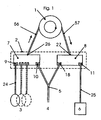
- FIG. 1 The principle of the peritoneal dialysis system according to the invention is shown in a schematic way in figure 1 . It includes a pump 1, a liquid distribution system 2 (also named cartridge) comprising a first hub chamber 7 and a second hub chamber 8.
- the first chamber 7 includes a pump inlet 26 connected to the pump 1 via a pump enter line 56, a liquid supply port 9 with valve connected to supply means, e.g. to bags 3, via a liquid supply line 24 and a patient port 10 with valve connected to a patient 4 via a patient line 5.
- the second chamber 8 includes a pump outlet 27 connected to the pump 1 via a pump exit line 57, a drain port 11 with valve connected to a drain collector 6 via a drain line 25 and a patient port 18 with valve connected to a patient 4 via a patient line 5.
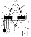
- Figure 1A shows the "fill" phase where liquid is supplied to the patient 4 from and through the following elements : Bag 3 - Liquid supply line 24 - (open) liquid supply port 9 - First chamber 7 - Pump inlet 26 - Pump enter line 56 - Pump 1 - Pump exit line 57 - Pump outlet 27 - Second chamber 8 - (open) Patient port 18 - Patient line 5 - Patient 4 .
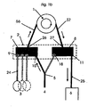
- Figure 1B shows the "drain" phase where liquid is drained from and through the following elements : Patient 4 - Patient line 5 - (open) Patient port 10 - First chamber 7 - Pump inlet 26 - Pump enter line 56 - Pump 1 - Pump exit line 57 - Pump outlet 27 - Second chamber 8 - (open) Drain port 11 - Drain line 25 - Drain collector 6 .
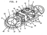
- FIG 2 shows an assembly constituted by a pumping element 1 and a cartridge 2. Both elements are fixed together but may be separated.
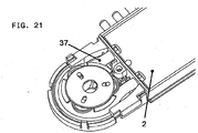
- Figure 21 shows a better view of the fixation between both elements.
- the pumping element 1 is fixed to the cartridge 2 by vibration attenuation means in order to minimize the vibration on cartridge 2 when the pump is operating.
- the upper face of the cartridge contains a first hub chamber 7 , a second distinct hub chamber 8 and a cavity 15 which forms part of a pressure sensor.
- the first chamber hub chamber 7 has three liquid supply ports 9, one patient port 10, one pump inlet 26 and a cavity 36 which forms part of a pressure sensor.
- the second hub chamber 8 has a patient port 18, a drain port 11 and a pump outlet 27.
- the pumping element 1 comprises a pump casing 45 which contains three rollers 22 maintained around the pump casing center by a roller separator 12. The space between the roller-roller separator element and the pump casing defines a pump race 21 in which a flexible tube 37 is placed. The flexible tube being connected with the pump enter 56 and exit 57 lines.
- the rollers 22 may be motor driven by a shaft 52 (not shown on figure 2 ) in such a way as to progressively compress the flexible tube 37 resulting thereby in a peristaltic movement along the flexible tube 37.
- liquid is supplied via one tube connector 53 and liquid supply port 9 to the first hub chamber 7. It then enters the pump 1 through the pump inlet 26, moves along the flexible tube 37, enters the second hub chamber 8 through the pump outlet 27 and goes to the patient 4 via patient port 18 and patient line 5.
- liquid leaves the patient 4 enters the first hub chamber 7 via patient port 10. It then enters the pump 1, moves along the flexible tube 37, enters the second hub chamber 8 and goes to the drain collector 6 via drain port 11, drain tube connector 54 and drain line 25.
- each bag 3 may contain a specific liquid.
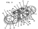
- the cartridge 2 of figure 3 is identical to the cartridge of figure 2 with the exception of an additional cavity, namely a warmer chamber 17, which includes a warmer port 19 and a patient port 16.
- the warmer port 19 is connected to a warmer 28 (not shown on figure 3 ) via a warmer tube connector 55 and a warmer exit line 30.
- the patient port 16 is connected to the patient line 5.
- the second hub chamber 8 contains a warmer port 38 connected to a warmer 28 (not shown on figure 3 ) via a warmer tube connector 23 and a warmer enter line 29.
- liquid is supplied via one tube connector 53 and liquid supply port 9 to the first hub chamber 7. It then enters the pump 1, moves along the flexible tube 37, enters the second hub chamber 8, moves into the warmer 28 via warmer port 38, enters the warmer chamber 17 via warmer port 19 through the tube connector 55 and goes to the patient 4 via patient port 16 and patient line 5.
- the pump 1 is unidirectional, i.e. whatever the pumping phase is, liquid in the flexible tube 37 always moves in the same direction.
- This feature provides several advantages. In particular a higher precision in the liquid exchange due to the same flow speed for both the fill and drain phases and a longer life time.
- peristaltic pumps are usually accurate within +/- 5%. As such, peristaltic pumps cannot be used for peritoneal dialysis since the volume which is filled within the patient cavity requires to be drained in the same amount within +/-2%, otherwise the peritoneal cavity could be overfilled (e.g.
- the invention provides a method whereby the conventional pump is used in a unidirectional way which insures the same accuracy for both the fill and the drain phase (usually within +/-2%) and therefore an appropriate balance of fluid.
- the volume filled with such a pump may be inaccurate within +/-5%, but since the same cassette with the same flow speed characteristics (namely the same flow direction) is used, the balance can be insured within +/-2% as required for the therapy. If the cassette would be used in both directions, the difference in flow speed would be within +/-5% due to the non parallel behavior of peristaltic pumps, in particular over time.
- the precision in the liquid exchange is maintained even if the pump flow rate changes after a certain time due to aging of the tubing since the fill and drain are operated within a time window which is small in comparison to the time in which the flow speed is altered by aging (e.g. a flow alteration of the pump of approximately 1% per 20 liters of fluid pumped, with exchanged volumes of approximately 2 liters per cycle).
- a flow alteration of the pump of approximately 1% per 20 liters of fluid pumped, with exchanged volumes of approximately 2 liters per cycle.
- the use of the cassette in one direction enables a better control over the aging of the tubing and, therefore, a better prediction of the impact on the pumping accuracy.
- Figure 4 is a transparent view of the cartridge which better shows how the different elements are connected.
- a cartridge bottom view is shown on figure 5 .
- the tubing system in the lower face and the cavities of the upper face are all made within one single part, e.g. an injected part of plastic material.
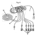
- Figure 6 shows an assembly including the cartridge 2 of figure 3 fixed to a pumping element 1, a patient line 5, supply bags 3, a warmer enter line 29, a warmer outer line 30 and a warmer pouch 28 which is essentially made of a fluid circuit within a plastic bag (e.g. PVC) to be put into contact with a warming plate.
- a fluid circuit within a plastic bag e.g. PVC
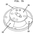
- Figure 7 shows a cartridge identical to the one of figure 3 where the rollers are part of the cycler rather than of the cartridge.
- the pumping element 1 which only contains the tube and tubing race and the cartridge 2 are forming a single element.
- the rollers which are part of the cycler and therefore re-usable rather than disposable with the cardridge, have a conical shape so as to allow the rollers to be self inserted in the pump race.
- the cartridge is more simple to manufacture and contains less parts. No other insertion mechanism is required, since the tube is automatically compressed on the race while the rollers are penetrating into the cartridge.
- the use of conical rollers 22 results in a more constant speed of the liquid along the flexible tube 37.
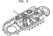
- Figure 8 shows the assembly of figure 7 without the rollers 22 and the roller element.
- roller shapes may be used, e.g. spherical or cylindrical.
- the embodiment of figure 9 only differs from the one of figure 8 in that the pump casing 45 is made out of two parts with an interface between the pumping element 1 and the cartridge 2.
- This configuration offers an improved assembly process of the pump and the possibility to add means to limit the propagation of the vibrations from the pump 1 to the cartridge 2.
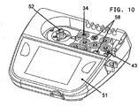
- Figure 10 shows a cycler 51 without cartridge 2 and pumping element 1 . It contains a driving zone which includes a motor shaft 52 for the rollers 22 and several actuators 34.
- the cycler 51 also includes an air sensor 43 situated close to the patient line 5 when the cartridge 2 is inserted.
- the air sensor may be made of a piezo emitter and a piezo receiver.
- Figure 11 represents the embodiment of figure 2 with a flexible membrane 13 covering the hub chambers 7,8 and the pressure sensor cavity 15.
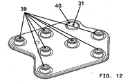
- the upper face of the membrane 13 (see figure 12 ) contains several valve elements having a cylindrical cavity 39 and a pressure sensor area 31 with a ply 40 around its periphery.
- the valve elements 39 are designed to tightly close the ports when the membrane 13 moves downwardly.
- the membrane 13 On its bottom face (see figure 13 ) the membrane 13 contains a semi-circular flange 32 around the pressure sensor area and annular liquid tight joints.
- the cartridge 2 includes liquid tight joints arranged in such a manner that they allow a liquid tight connection between the cartridge 2 and the membrane 13.
- the membrane is molded.
- the membrane 13 is made of silicone.
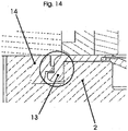
- the membrane 13 is press-fitted to the cartridge 2 along its periphery with a membrane frame 14 (see figure 14 ).
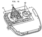
- Figure 15 shows the cycler of figure 10 in an open state which includes a pump motor and a coder 42 .
- the rectangle 41 represents the cartridge loader.
- Figure 16 shows a cartridge loader comprising cartridge loader shafts 46, a cartridge loader frame 47, a cartridge loader linear cam 48 and a cartridge loader motor 49 .
- the two displacement parts 48' and 48" represent two different positions of the loader in an open and closed position only for explanation reasons.
- the cartridge loading mechanism allows a tight connection between the membrane and the valves and the cartridge. In order to insure proper positioning of the cartridge onto the valve actuators, as well as pressure sensor and air sensor onto the right place, the cartridge is maintained into the loading mechanism which progressively moves the cartridge in an axis which is perpendicular to its surface.
- the axis or the rollers can be inserted in the right position to ensure proper functioning of the pump.
- the same movement can also insure appropriate pressure on the surfaces which requires to be maintained together, such as for tightness control on the membrane and/or tubing of the pump.
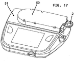
- Figure 17 shows the cycler 51 of figure 10 containing a cartridge 2.
- the cycler 51 has an insertion slot 50 in an open position.
- Figure 18 shows the same cycler 51 but with an insertion slot in a closed position.
- Figure 19 represents an actuator 34 with its plunger 35 clipped in its corresponding valve element 39 of the membrane.
- the actuator 34 may be a magnet or an electromagnetic element.
- the plunger 35 and the valve element 39 are designed to move together when the actuator is activated.
- Figure 22a and 22b shows the plunger 35 and the valve element 39 in a separate position ( fig. 22a ) before insertion and in an activated position ( fig. 22b ) after insertion.
- One embodiment of the invention is to insure a proper insertion of the actuator head into the membrane clipping part by having the length of the part of the actuator head to be inserted into the clip of the membrane to be longer than the possible displacement of the actuator head, so as to ensure that the actuator head is always properly inserted into the clip of the membrane.
- the actuators head would pass the clipping equilibrium position before the end of the translation, so that the remaining translation will ensure clipping of the actuator head into the membrane.
- the front view of figure 20 illustrates a pressure sensor 44 which may be used with the independent pressure sensor cavity 15 of the cartridge 2 or with the pressure sensor cavity 36 of the first hub chamber 7.
- the ply 40 makes the pressure sensor less sensitive to the elasticity of the membrane 13 in the sensor pressure area.
- the shape of the cavity 15 shall be made such that air can be eliminated easily when fluid is passing into the cavity (e.g. by having a round shaped bottom of the cavity within the direction of the flow).
- each port has a dedicated valve. This is not the case for the pump inlet and the pump outlet which are always kept open.
- the cycler or the cartridge-pumping element assembly may contain a window for detecting correct positioning of the flexible tube of the pump as shown in figure 21 (circle).
- the pressure is preferably always maintained positive with respect to the drain. This is a safety measure which avoids said contaminated liquid to potentially infect the patient.
- the liquid pressure entering and exiting the cartridge is sensed and, if necessary, the pump flow rate is corrected in accordance with the pressure difference.
- This pressure difference is better calculated at the initial priming phase of the system, where the pressure is directly related to the positioning of the liquid bags 3 and the patient position relative to the cycler.
- the pump flow rate may be regulated according to a predetermined deterioration of the tubing which is known from the characteristics of the tubing.
- the drain phase may be limited as to its duration in function of the drain speed, the drain speed having to be reduced when the patient peritoneal cavity pressure decreases, typically between 30 ml/min and 120 ml/min instead of a nominal 200 ml/min speed.
- This feature is particularly interesting because the dialysis efficiency is directly related to the time the liquid stays in the peritoneal cavity and the duration required to fully drain the peritoneal cavity may limit this time without a significant impact with regard to the peritoneal fluid characteristics.
- one method of the invention would be to determine at which speed it is not worth continuing draining the patient entirely and rather fill the patient with fresh fluid, taking into consideration the remaining fluid volume in the peritoneal cavity which has not been expelled and expected ultra-filtration additional volume to avoid overfill.
- the cycles will therefore be all different, based on reaching a pre-determined drainage speed or a pre-determined decrease profile of the drainage speed, so that the efficient time of dialysis will be increased.
- An example of drainage speed on a patient is given in the figure 25 , where, for each column which is divided in three parts, the upper part corresponding to a limit of drainage speed at which it is, for example, not worth continuing the drainage even if the next fill volume will not be a full fill.
- a tidal at e.g. 80%
- the method under the invention is adapting each drainage to the actual drainage speed, trying to empty as much as possible without compromising on the efficacy of the peritoneal dialysis.
- some limits can be set, where a minimum of drainage volume has to be reached before such a limitation takes place for each cycle.
- Another method under the present invention consists to fill always as much volume, within certain limits to be set for the patient, until a certain pressure in the peritoneal cavity is reached.
- the peritoneal dialysis can be improved since the efficiency is related to the amount of fluid filled at every cycle.
- the pump shall fill the patient until a certain pressure is reached (e.g. 10cm water) and stop only once such pressure is reached or a certain maximum volume is reached. Accordingly, it is important to measure continuously the pressure during the dwell time to make sure that no over pressure is reached, such as due to the ultra-filtration.
- One possibility is also to always fill up to such a limited pressure and/or volume and drain at a certain interval thereafter a certain volume to compensate for expected ultra-filtration.
- Another possibility is to increase the ultra-filtration during the last cycle, by using e.g. low sodium concentrated solution.
- Figure 26 illustrates another embodiment which uses peristaltic finger elements working on a hemispheric channel in the hard plastic part.
- the channel and the liquid distribution system are covered by a single membrane.
- a peristaltic pumping effect is obtained by pressing down these fingers in a sequence.
- This performs a digital type peristaltic pump with a high accuracy, which remains in particular independent of inlet and outlet pressure changes.
- the fingers are moved in a progressive way to simulate a peristaltic movement.
- Those fingers can be operated either individually, e.g. by electric means, or by a mechanical cam which simulates the peristaltic movement and which is rotating along the fluid channel (e.g. a rotating disk with a variable thickness which displays a wave on its surface in contact with the finger elements).
- those fingers can be clipped onto the membrane and be operated individually in the same mariner as the valves are, or by a rotating disk cam.
- the advantage is that the position of the membrane is perfectly known in both push and pull direction, to ensure that the peristaltic pumping is not depending on the pressure.
- the embodiment of figure 27 only differs from the embodiment of figure 26 in that the membrane includes cavities to receive and guide the finger elements (e.g. by clipping means).
- the membrane is biocompatible, allows a simple sealing to the liquid distribution system e.g. by welding, sticking, gluing, laser or heat melting.
- the membrane should be made in a material avoiding the release of particles due to mechanical stress or self migration due to the material itself (e.g. KratonTM, SantopreneTM, BiopureTM, PebaxTM or Polyurethane).
- the membrane must be soft and elastic in order to properly perform valve and / or pump functionalities. It is also possible to use multi-layer material with in inner layer (on the fluid side) which is more biocompatible and with low spallation characteristics.
- the membrane is also covering the fluid pumping channel, at 45', to ensure possible operation with either conical rollers or ball rollers which are part of the cycler.
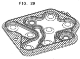
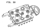
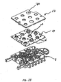
- Figures 28 to 31 illustrates a molded frame which is adapted to cover in a tight manner the space between the hub chambers, each space above said hub chambers being covered by a flexible membrane, preferably made of injected silicone or elastic biocompatible material.
- the molded frame and silicone or elastic biocompatible membrane can be obtained by over-molding techniques.
- the system according to the present invention may furthermore include free flow preventing means which prevent the flow of fluid towards or from the liquid distribution system when it is released from the cycler.
- This preventing means may be made of a mechanical clamp around the patient line, which is not clamping during the treatment will be closed automatically due to the movement of a loading mechanisms by releasing the cartridge, such as by clipping mechanism.
- Figure 32 illustrates such a clamping mechanism which consists of a slotted clamping member 60 movably fixed to the liquid distribution system 2 via a flexible U shape member 61.
- Figure 32 also shows a shaft 62 which is fixed to the cycler (not shown). In the illustrated position, the liquid distribution system 2 is not fixed to the cycler. When fixation occurs, the shaft 62 is inserted through the opening 65 of the flexible U shape member 61 and retained to it by a retaining lip 63.
- the patient line is closed by a special designed, so called “lip valve” which is normally closed. Due to a mechanical pin in the cycler the lip valve, as an integrated part of the membrane, will be open by simply pressed down with the pin coming from the cycler by mechanical movement.
- Figures 33 to 37 show another embodiment of the invention, similar to the embodiment of figure 14a , but which differs in that the membrane 13 is not fixed by a clipping frame but by a rigid plate 67 which covers the membrane 13 over its entire surface.
- the rigid plate has holes 70 adapted to receive the membrane actuator clips 39 and pins 68 adapted to be fixed on the cartridge 2.
- the membrane is provided with holes 69 which are designed to let the pins 68 pass through.
- the bottom side of the membrane 13 is provided with a flange 73 which is situated around the actuator clip 39.
- the cartridge 2 surface just below the flange 73 is provided with a groove 72.
- the groove 72 is adapted to receive and hold the flange 73 sufficiently enough to maintain a fluid tight connection between the membrane 13 and the cartridge 2.
- the system comprises one or several flow sensor(s) which is/are preferably situated close to the pump inlet and/or outlet.
- the flow sensor may be of any type suitable for the intended purpose. For instance, but not exclusively, it may be of the mechanical (e.g. turbine flowmeter), mass (e.g. thermal flowmeter), electronic, magnetic or US type.
Landscapes
- Health & Medical Sciences (AREA)
- Heart & Thoracic Surgery (AREA)
- Urology & Nephrology (AREA)
- Emergency Medicine (AREA)
- Engineering & Computer Science (AREA)
- Hematology (AREA)
- Anesthesiology (AREA)
- Biomedical Technology (AREA)
- Vascular Medicine (AREA)
- Life Sciences & Earth Sciences (AREA)
- Animal Behavior & Ethology (AREA)
- General Health & Medical Sciences (AREA)
- Public Health (AREA)
- Veterinary Medicine (AREA)
- Mechanical Engineering (AREA)
- General Engineering & Computer Science (AREA)
- External Artificial Organs (AREA)
Claims (51)
- System zur Durchführung der Flüssigkeitsverabreichung an einem Patienten, das Folgendes umfasst:- eine Flüssigkeitspumpe (1),- ein Flüssigkeitsverteilungssystem (2), das so mit der Pumpe (1) verbunden ist, dass Flüssigkeit vom Flüssigkeitsverteilungssystem (2) zur Pumpe (1) und umgekehrt fließen kann,- ein Flüssigkeitszufuhrmittel (3) zur Zufuhr von Flüssigkeit zu einem Patienten (4) über das Flüssigkeitsverteilungssystem (2) und die Pumpe (1),- eine Patientenleitung (5) zur Verbindung des Flüssigkeitsverteilungssystems (2) mit einem Patienten (4),- und ein Erwärmungssytem (28),dadurch gekennzeichnet, dass das Flüssigkeitsverteilungssystem (2) zwei verschiedene Ansatzkammern (7, 8), die durch einen Zwischenraum und einen Hohlraum (17) voneinander getrennt sind, umfasst, wobei die erste Ansatzkammer (7) zumindest eine Flüssigkeitszufuhröffnung mit zugeordnetem Ventilmittel (9), eine Patientenöffnung mit zugeordnetem Ventilmittel (10) und einen Pumpeneingang (26) aufweist, wobei die zweite Ansatzkammer (8) zumindest eine Patientenöffnung (18) mit zugeordnetem Ventilmittel und einen Pumpenausgang (27) aufweist, wobei der Hohlraum (17) eine Erwärmungsöffnung (19) und eine Patientenöffnung aufweist, wobei die Patientenöffnung (18) der zweiten Ansatzkammer (8) mit der Erwärmungsöffnung (19) über das Erwärmungssystem (28) verbunden ist
wobei das System ferner ein Kontrollmittel umfasst, das so angeordnet ist, dass es die Patientenöffnung (10) der ersten Ansatzkammer (7) verschließt, wenn die Flüssigkeitszufuhrleitung (9) offen ist, und umgekehrt. - System nach Anspruch 1, worin die zweite Ansatzkammer (8) ferner zumindest eine Drainageleitung mit zugeordneten Ventilmitteln (11) umfasst, wobei das Kontrollmittel auch die Patientenöffnung (18) der zweiten Ansatzkammer (8) verschließen kann, wenn die Drainageöffnung (11) offen ist, und umgekehrt.
- System nach Anspruch 2, worin das Flüssigkeitsverteilungssystem (2) nur zwei Ansatzkammern (7, 8) aufweist.
- System nach Anspruch 1, worin das Erwärmungssystem (28) eine Erwärmungsinlineleitung ist.
- System nach Anspruch 4, worin die Erwärmungsinlineleitung eine darin enthaltene Wärmeplatte umfasst, wobei diese Wärmeplatte von einem Wärmebeutel, wie z.B. einer Socke, abgedeckt ist.
- System nach Anspruch 5, worin der Wärmebeutel aus einem Flüssigkeitskanal besteht, der die Flüssigkeit zwingt, für eine bestimmte Zeitdauer mit einer vorgegebenen Strömungsrate in diesem Wärmemittel zu bleiben.
- System nach einem der vorhergehenden Ansprüche, worin die erste Ansatzkammer (7) mehrere Flüssigkeitszufuhröffnungen mit jeweiligen Ventilmitteln (9) aufweist.
- System nach dem vorhergehenden Anspruch, worin die Flüssigkeitszufuhröffnungen (9) jeweils mit Flüssigkeitszufuhrmitteln, die jeweils eine andere Art von Flüssigkeit enthalten, verbunden sind.
- System nach einem der vorhergehenden Ansprüche, worin die Flüssigkeitspumpe eine Peristaltikpumpe ist.
- System nach dem vorhergehenden Anspruch, worin die Peristaltikpumpe unidirektional ist.
- System nach einem der vorhergehenden Ansprüche, worin die Flüssigkeitspumpe (1) aus einem Schlauch und einer Rollfläche besteht, auf der der Schlauch zusammengedrückt wird, wenn die Patrone in eine Pumpenvorrichtung mit Rollen eingeführt wird.
- System nach dem vorhergehenden Anspruch, worin die Rollen (22) so konisch geformt sind, dass sie von selbst in den Pumpenlaufring, d.h. ohne weiteren Mechanismus, eingeführt werden.
- System nach Anspruch 11, wobei die Rollen kugelförmig sind.
- System nach einem der vorhergehenden Ansprüche 1 bis 10, worin die Flüssigkeitspumpe (1) einen flexiblen oder teilweise flexiblen Kanal und eine Reihe von beweglichen Fingerelementen umfasst, die nacheinander über dem Kanal angeordnet sind, wobei jedes Fingerelement in einer Richtung bewegt werden kann, die im Wesentlichen lotrecht zum Kanal ist, wobei alle Fingerelemente eine peristaltische Bewegung entlang des Kanals auslösen können.
- System nach dem vorhergehenden Anspruch, worin jedes Fingerelement einen konvexen Boden, der sich an die Innenseite des Kanals anpassen kann, und einen Schaft, der mit einem Stellelement verbunden werden kann, umfasst.
- System nach einem der vorhergehenden Ansprüche, worin die Flüssigkeitspumpe (1) und das Flüssigkeitsverteilungssystem (2) zur Bildung einer einzelnen Patrone aneinander befestigt sind.
- System nach dem vorhergehenden Anspruch, worin die Flüssigkeitspumpe (1) durch ein Vibrationsabschwächungsmittel an dem Flüssigkeitsverteilungssystem (2) befestigt ist, um die Vibration auf dem Flüssigkeitsverteilungssystem (2) im Betrieb der Pumpe zu minimieren.
- System nach einem der vorhergehenden Ansprüche, worin alle Ansatzkammern, einschließlich Öffnungen, aus einem einzigen Stück gefertigt sind.
- System nach dem vorhergehenden Anspruch, worin das einzige Stück ein Spritzgussteil aus Plastik ist.
- System nach Anspruch 1, worin jede Ansatzkammer (7, 8) mit einer oberen Wand aus einer flexiblen Membran (13) verschlossen ist, wobei die Membran Ventilelemente (39) aufweist, die auf jeder der Öffnungen oder Öffnungen mit Ventilelementen sitzen, wobei die Ventilelemente (39) die Öffnung oder Öffnung verschließen können, wenn die Membran (13) sich nach unten bewegt.
- System nach Anspruch 1, worin jede Ansatzkammer (7, 8) mit einer oberen Wand aus einer flexiblen Membran (13) verschlossen ist, wobei die Membran Klemmmittel zum Anklemmen der Elemente, wie z.B. Ventilbetätigungs- oder Fingerelemente, aufweist.
- System nach einem der Ansprüche 20 bis 21, worin die Membran geformt ist.
- System nach dem vorhergehenden Anspruch, worin die Membran aus einem der folgenden Materialien besteht: Silikon oder Polyurethan.
- System nach dem vorhergehenden Anspruch, worin die Membran flüssigkeitsdichte Verbindungsstellen aufweist.
- System nach einem der vorherigen Ansprüche 20 bis 24, worin die Membran sich so erstreckt, dass sie auch die Flüssigkeitspumpe (1) abdeckt.
- System nach Anspruch 11, 12 oder 13, worin die Flüssigkeitspumpe (1) einen flexiblen oder teilweise flexiblen Kanal umfasst wobei die Membran den Kanal über eine schräge Ebene, vorzugsweise von 45°, abdeckt, um eine durch Rollen oder ähnliche Elemente ausgelöste peristaltische Bewegung zu gestatten.
- System nach einem der vorhergehenden Ansprüche, das einzelne Stellelemente oder einen Nocken (z.B. eine Scheibe mit einer Welle) zur Auslösung einer peristaltischen Bewegung umfasst.
- System nach einem der vorhergehenden Ansprüche, worin die einzelnen Stellelemente von Fingern betätigt werden können, die an der Membran festgeklemmt sind.
- System nach einem der vorhergehenden Ansprüche, worin das Flüssigkeitsverteilungssystem flüssigkeitsdichte Verbindungsstellen aufweist, die so angeordnet sind, dass sie eine flüssigkeitsdichte Verbindung zwischen dem Flüssigkeitsverteilungssystem und der auf ihm sitzenden Membran gestatten.
- System nach einem der Ansprüche 20 bis 23, worin die Membran vorstehende Elemente aufweist, die zur flüssigkeitsdichten Verbindung zwischen den Ansatzkammern bestimmt sind.
- System nach dem vorhergehenden Anspruch, worin jedes der Ventilelemente einen Hohlraum umfasst, der zur Aufnahme und zum Halten des Kolbens eines Stellelements bestimmt ist, wobei der Hohlraum eine Höhe aufweist, die im Wesentlichen zumindest der Ventilverdrängung entspricht.
- System nach einem der Ansprüche 20 bis 26 und 29 bis 31, worin die Membran (13) entlang ihres Außenrands in das Flüssigkeitsverteilungssystem eingepresst ist, wobei die Membran (13) ferner von einem Rahmen (14) gehalten wird.
- System nach einem der Ansprüche 20 bis 26 und 29 bis 32, worin die Membran (13) einen Teil (15) aufweist, der Teil eines Drucksensors bildet.
- System nach dem vorhergehenden Anspruch, worin der aktive Bereich des Drucksensors flexibler ist als der restliche Bereich.
- System nach Anspruch 33 oder 34, worin der Drucksensor die Form einer Scheibe mit aufgenommenem Umfang aufweist, wobei die Scheibe ferner eine ringförmige Lage umfasst.
- System nach einem der Ansprüche 33 bis 35, worin der Drucksensor auf der Patientenleitung unabhängig von den Ansatzkammern angeordnet ist.
- System nach einem der Ansprüche 33 bis 35, das ferner einen zweiten Drucksensor umfasst, wobei der zweite Drucksensor mit der ersten Ansatzkammer verbunden ist.
- System nach einem der vorhergehenden Ansprüche, worin das Flüssigkeitsverteilungssystem einen Luftsensor aufweist, der auf der Seite der Patientenleitung angeordnet ist.
- System nach einem der vorhergehenden Ansprüche, das einen Patronenlademechanismus umfasst, der eine enge Verbindung zwischen der Membran und den Ventilen und dem Flüssigkeitsverteilungssystem gestattet.
- System nach einem der vorhergehenden Ansprüche, das ein Strömungsblockiermittel umfasst, das die Strömung zum oder vom Flüssigkeitsverteilungssystem blockieren kann, wenn dieses aus dem System freigegeben wird.
- System nach dem vorhergehenden Anspruch, worin das Blockiermittel eine auf der Patientenleitung angeordnete mechanische Klemme ist.
- System nach Anspruch 40, worin das Blockiermittel ein auf der Patientenleitung angeordnetes Lippenventil ist, wobei das System ferner einen beweglichen Stift umfasst, der das Lippenventil öffnen kann, wenn das Flüssigkeitsverteilungssystem aus dem System freigegeben wird.
- System nach einem der vorherigen Ansprüche 20 bis 42, das einen geformten Rahmen umfasst, der den Zwischenraum zwischen den Ansatzkammern abdecken kann, wobei jeder Zwischenraum über den Ansatzkammern von einer flexiblen Membran abgedeckt ist.
- System nach dem vorhergehenden Anspruch, worin der geformte Rahmen z.B. durch Ultraschall, Laserschweißen, Kleben oder thermische Verbindung an dem Flüssigkeitsverteilungssystem befestigt ist.
- System nach Anspruch 43 oder 44, worin der geformte Rahmen zumindest teilweise aus Silikon oder Polyurethan besteht.
- System nach einem der Ansprüche 43 bis 45, worin der Rahmen, die Membran und das Flüssigkeitsverteilungssystem durch eine Umspritzungstechnik erhalten werden.
- System nach einem der Ansprüche 20 bis 46, wobei eine doppellagige Membran verwendet wird, die Verschütten oder Freisetzung von Teilchen in die Flüssigkeit im Gebrauch verhindern kann.
- System nach einem der vorhergehenden Ansprüche, das ferner ein Fenster zum Nachweis der korrekten Positionierung des Schlauchs umfasst.
- System nach einem der Ansprüche 20 bis 26 und 29 bis 31, das ferner eine starre Platte (67) umfasst, die die Membran (13) abdeckt und hält, wobei die starre Platte (67) Löcher (70) umfasst, durch die bewegliche Elemente hindurch geführt werden können.
- System nach dem vorhergehenden Anspruch, worin die starre Platte (67) Stifte (68) aufweist, die auf der Membranseite angeordnet sind, wobei die Stifte (68) an dem Flüssigkeitsverteilungssystem (2) befestigt werden können.
- Flüssigkeitsverteilungssystem (2) für ein System zur Durchführung einer Flüssigkeitsverabreichung an einem Patienten wie in einem der vorherigen Ansprüche definiert.
Applications Claiming Priority (3)
| Application Number | Priority Date | Filing Date | Title |
|---|---|---|---|
| CH0300527 | 2003-07-31 | ||
| CH2004000040 | 2004-01-26 | ||
| PCT/CH2004/000480 WO2005009511A2 (en) | 2003-07-31 | 2004-08-02 | A system for performing peritoneal dialysis |
Publications (3)
| Publication Number | Publication Date |
|---|---|
| EP1648536A2 EP1648536A2 (de) | 2006-04-26 |
| EP1648536B1 EP1648536B1 (de) | 2011-05-18 |
| EP1648536B2 true EP1648536B2 (de) | 2017-12-20 |
Family
ID=34105201
Family Applications (1)
| Application Number | Title | Priority Date | Filing Date |
|---|---|---|---|
| EP04738120.7A Expired - Lifetime EP1648536B2 (de) | 2003-07-31 | 2004-08-02 | System zur durchführung von peritonealdialyse |
Country Status (11)
| Country | Link |
|---|---|
| US (2) | US8585634B2 (de) |
| EP (1) | EP1648536B2 (de) |
| JP (1) | JP4589319B2 (de) |
| CN (1) | CN1829545B (de) |
| AT (1) | ATE509648T1 (de) |
| AU (1) | AU2004259149B2 (de) |
| BR (1) | BRPI0413074A (de) |
| CA (1) | CA2533171C (de) |
| IL (1) | IL173412A (de) |
| RU (1) | RU2006104656A (de) |
| WO (1) | WO2005009511A2 (de) |
Families Citing this family (42)
| Publication number | Priority date | Publication date | Assignee | Title |
|---|---|---|---|---|
| WO2007091217A1 (en) | 2006-02-08 | 2007-08-16 | Debiotech S.A. | Peritoneal dialysis system |
| CA2574537C (en) * | 2007-01-19 | 2014-03-25 | Joseph E. Dadson, Sr. | System and method for peritoneal dialysis |
| US9044542B2 (en) | 2007-12-21 | 2015-06-02 | Carticept Medical, Inc. | Imaging-guided anesthesia injection systems and methods |
| EP2231230A4 (de) | 2007-12-21 | 2013-01-23 | Carticept Medical Inc | Gelenkinjektionssystem |
| US8545440B2 (en) * | 2007-12-21 | 2013-10-01 | Carticept Medical, Inc. | Injection system for delivering multiple fluids within the anatomy |
| US9147045B2 (en) * | 2008-07-09 | 2015-09-29 | Baxter International Inc. | Peritoneal equilibration test and dialysis system using same |
| AU2010245166B2 (en) | 2009-05-06 | 2014-04-17 | Alcon Inc. | Multiple segmented peristaltic pump and cassette |
| WO2011017215A1 (en) * | 2009-08-04 | 2011-02-10 | Fresenius Medical Care Holdings, Inc. | Dialysis systems, components, and methods |
| US20110137231A1 (en) | 2009-12-08 | 2011-06-09 | Alcon Research, Ltd. | Phacoemulsification Hand Piece With Integrated Aspiration Pump |
| DE102010005745A1 (de) * | 2010-01-26 | 2011-07-28 | Fresenius Medical Care Deutschland GmbH, 61352 | Dialysemaschine |
| CN102198299B (zh) * | 2010-03-23 | 2013-01-16 | 上海白塔医药科技有限公司 | 一种医用循环式冷却注射泵 |
| EP2383004A1 (de) * | 2010-04-30 | 2011-11-02 | Fresenius Medical Care Deutschland GmbH | Membran für einen Druckdom |
| JP6049685B2 (ja) | 2011-03-23 | 2016-12-21 | ネクステージ メディカル インコーポレイテッド | 腹膜透析使い捨てユニット、コントローラ、腹膜透析システム |
| US9861733B2 (en) | 2012-03-23 | 2018-01-09 | Nxstage Medical Inc. | Peritoneal dialysis systems, devices, and methods |
| USD681210S1 (en) * | 2011-04-07 | 2013-04-30 | Fresenius Medical Care Holdings, Inc. | Dialysis fluid line carrier |
| CA2839460C (en) * | 2011-06-24 | 2017-08-22 | Richard W.C. LO | Multi-container systems and uses thereof |
| US9649436B2 (en) | 2011-09-21 | 2017-05-16 | Bayer Healthcare Llc | Assembly method for a fluid pump device for a continuous multi-fluid delivery system |
| WO2014076519A1 (fr) | 2012-10-29 | 2014-05-22 | Debiotech S.A. | Dispositif de traitement extra corporel du sang |
| CN104640523B (zh) | 2012-12-11 | 2017-07-04 | 爱尔康研究有限公司 | 具有集成的抽吸和冲洗泵的白内障超声乳化手柄 |
| US9962288B2 (en) | 2013-03-07 | 2018-05-08 | Novartis Ag | Active acoustic streaming in hand piece for occlusion surge mitigation |
| US9126219B2 (en) | 2013-03-15 | 2015-09-08 | Alcon Research, Ltd. | Acoustic streaming fluid ejector |
| US9545337B2 (en) | 2013-03-15 | 2017-01-17 | Novartis Ag | Acoustic streaming glaucoma drainage device |
| US9915274B2 (en) | 2013-03-15 | 2018-03-13 | Novartis Ag | Acoustic pumps and systems |
| US9750638B2 (en) | 2013-03-15 | 2017-09-05 | Novartis Ag | Systems and methods for ocular surgery |
| US9693896B2 (en) | 2013-03-15 | 2017-07-04 | Novartis Ag | Systems and methods for ocular surgery |
| DK3206733T3 (da) | 2014-10-17 | 2020-06-08 | Debiotech Sa | Leveringssystem og driftsmodus |
| ES3030489T3 (en) | 2015-01-09 | 2025-06-30 | Bayer Healthcare Llc | Multiple fluid delivery system with multi-use disposable set and features thereof |
| JP2018519887A (ja) | 2015-06-03 | 2018-07-26 | デビオテック ソシエテ アノニム | 腹膜透析治療システム及び動作の方法 |
| EP3302614B1 (de) | 2015-06-05 | 2020-08-05 | Debiotech S.A. | Prüfung einer behandlung eines medizinischen fluids |
| US12329892B2 (en) | 2016-04-04 | 2025-06-17 | Mozarc Medical Us Llc | Dextrose concentration sensor for a peritoneal dialysis system |
| US10994064B2 (en) | 2016-08-10 | 2021-05-04 | Medtronic, Inc. | Peritoneal dialysate flow path sensing |
| CN206473610U (zh) * | 2016-09-28 | 2017-09-08 | 郑红光 | 一种用于腹膜透析的装置 |
| WO2018237375A1 (en) | 2017-06-24 | 2018-12-27 | Nxstage Medical, Inc. | Peritoneal dialysis fluid preparation and/or treatment devices methods and systems |
| WO2019087103A1 (en) * | 2017-10-31 | 2019-05-09 | Debiotech S.A. | Automated extracorporeal blood treatment apparatus |
| EP3501564A1 (de) * | 2017-12-20 | 2019-06-26 | Debiotech S.A. | Leicht bewegbare blutreinigungssysteme |
| US11364328B2 (en) | 2018-02-28 | 2022-06-21 | Nxstage Medical, Inc. | Fluid preparation and treatment devices methods and systems |
| CN112569418A (zh) * | 2019-09-29 | 2021-03-30 | 百特国际有限公司 | 自动腹膜透析循环仪 |
| EP3992982A1 (de) | 2020-10-28 | 2022-05-04 | Bellco S.r.l. | Dialysegerät und kommunikationsverfahren für eine dialysemaschine |
| US12329893B2 (en) | 2021-03-22 | 2025-06-17 | Mozarc Medical Us Llc | Single container preparation of peritoneal dialysis fluid |
| WO2022236053A1 (en) * | 2021-05-06 | 2022-11-10 | Baxter International Inc. | Automated peritoneal dialysis system including enhanced pressure sensing features |
| US12318517B2 (en) | 2021-10-25 | 2025-06-03 | Mozarc Medical Us Llc | Inline heater for a peritoneal dialysis system |
| US11965763B2 (en) | 2021-11-12 | 2024-04-23 | Mozarc Medical Us Llc | Determining fluid flow across rotary pump |
Citations (14)
| Publication number | Priority date | Publication date | Assignee | Title |
|---|---|---|---|---|
| US4980054A (en) † | 1983-08-15 | 1990-12-25 | Lavender Ardis R | System and method for mass transfer between fluids |
| US5078362A (en) † | 1990-03-15 | 1992-01-07 | Abbott Laboratories | Spring-biased valve for use in a positive displacement volumetic pump |
| US5437629A (en) † | 1994-04-14 | 1995-08-01 | Bei Medical Systems | Fluid delivery system for hysteroscopic endometrial ablation |
| DE4421126A1 (de) † | 1994-06-16 | 1995-12-21 | Fresenius Ag | Peritonealdialysegerät |
| US5478211A (en) † | 1994-03-09 | 1995-12-26 | Baxter International Inc. | Ambulatory infusion pump |
| JPH09108340A (ja) † | 1995-10-09 | 1997-04-28 | Baxter Internatl Inc | 腹膜透析用自動注排液装置 |
| WO1999006082A1 (en) † | 1997-07-28 | 1999-02-11 | 1274515 Ontario Inc. | Method and apparatus for performing peritoneal dialysis |
| EP0956876A1 (de) † | 1998-04-01 | 1999-11-17 | Fresenius Medical Care Deutschland GmbH | Kassette zur Förderung von Flüssigkeiten, insbesondere Dialyseflüssigkeiten |
| WO2000030701A1 (en) † | 1998-11-20 | 2000-06-02 | Gambro Ab | Method and apparatus for preventing protein loss with peritoneal dialysis |
| US6074359A (en) † | 1994-04-06 | 2000-06-13 | Baxter International Inc. | Method and apparatus for a tidal oscillating pulse peritoneal dialysis |
| WO2001019430A1 (en) † | 1999-09-16 | 2001-03-22 | Gambro Lundia Ab | Method and cycler for peritoneal dialysis |
| EP1121948A1 (de) † | 1998-10-07 | 2001-08-08 | Asahi Sakai | Vorrichtung und verfahren zur perfusion peritonealer dialyseflüssigkeit |
| DE10053441A1 (de) † | 2000-10-27 | 2002-05-16 | Fresenius Medical Care De Gmbh | Disposablekassette mit Dichtungsmembran sowie Ventilaktor hierfür |
| EP1277485B1 (de) † | 1995-08-30 | 2006-11-29 | Baxter International Inc. | System zum Infundieren einer Vielzahl von Lösungen in die Bauchhöhle eines Patienten |
Family Cites Families (32)
| Publication number | Priority date | Publication date | Assignee | Title |
|---|---|---|---|---|
| US2684829A (en) * | 1951-03-07 | 1954-07-27 | Hills Mccanna Co | Valve diaphragm |
| JPS59154259U (ja) * | 1983-04-01 | 1984-10-16 | 株式会社ウベ循研 | 血液用円錐形送液ポンプ |
| US4828545A (en) * | 1984-02-08 | 1989-05-09 | Omni-Flow, Inc. | Pressure responsive multiple input infusion system |
| US4586920A (en) * | 1984-07-09 | 1986-05-06 | Peabody Alan M | Continuous flow peritoneal dialysis system and method |
| US4778451A (en) | 1986-03-04 | 1988-10-18 | Kamen Dean L | Flow control system using boyle's law |
| US4976162A (en) | 1987-09-03 | 1990-12-11 | Kamen Dean L | Enhanced pressure measurement flow control system |
| US4826482A (en) | 1986-03-04 | 1989-05-02 | Kamen Dean L | Enhanced pressure measurement flow control system |
| US4758228A (en) * | 1986-11-17 | 1988-07-19 | Centaur Sciences, Inc. | Medical infusion pump with sensors |
| DE3723178C2 (de) * | 1987-07-14 | 1996-01-25 | Bodenseewerk Perkin Elmer Co | Verfahren und Vorrichtung zur Fließinjektionsanalyse in Kombination mit Atomabsorptionsspektroskopie |
| US5347629A (en) * | 1992-04-07 | 1994-09-13 | International Business Machines Corporation | Graphical user interface including updating of multiple panels using what you see is what you get (WYSIWYG) editor |
| FR2690715B1 (fr) * | 1992-04-30 | 1994-07-22 | Debiotech Sa | Pompe peristaltique a cassette munie d'un ensemble de detrompage. |
| US5302093A (en) * | 1992-05-01 | 1994-04-12 | Mcgaw, Inc. | Disposable cassette with negative head height fluid supply and method |
| US5350357A (en) * | 1993-03-03 | 1994-09-27 | Deka Products Limited Partnership | Peritoneal dialysis systems employing a liquid distribution and pumping cassette that emulates gravity flow |
| US5333643A (en) * | 1993-03-24 | 1994-08-02 | South Bend Controls, Inc. | Solenoid valve |
| US5462416A (en) | 1993-12-22 | 1995-10-31 | Baxter International Inc. | Peristaltic pump tube cassette for blood processing systems |
| US5427509A (en) | 1993-12-22 | 1995-06-27 | Baxter International Inc. | Peristaltic pump tube cassette with angle pump tube connectors |
| US5482440A (en) | 1993-12-22 | 1996-01-09 | Baxter Int | Blood processing systems using a peristaltic pump module with valve and sensing station for operating a peristaltic pump tube cassette |
| SE9400347L (sv) * | 1994-02-03 | 1995-07-17 | Gambro Ab | Apparat för peritonealdialys |
| ES2162923T3 (es) * | 1994-06-17 | 2002-01-16 | Baxter Int | Metodo y aparato para dialisis peritoneal de impulso depurado. |
| US5938634A (en) | 1995-09-08 | 1999-08-17 | Baxter International Inc. | Peritoneal dialysis system with variable pressure drive |
| US5683233A (en) * | 1996-10-18 | 1997-11-04 | Moubayed; Ahmad-Maher | Non-rolling type peristaltic pump having pressure plate mounted tube biasing means |
| US5840069A (en) * | 1996-04-04 | 1998-11-24 | Medtronic, Inc. | Implantable peristaltic pump techniques |
| DE19856744C2 (de) * | 1998-12-09 | 2003-06-26 | Plasmaselect Ag | Pumpschlauchsystem zur peristaltischen Förderung von flüssigen oder gasförmigen Medien |
| US6296450B1 (en) * | 1999-09-03 | 2001-10-02 | Baxter International Inc. | Systems and methods for control of pumps employing gravimetric sensing |
| DE10046651A1 (de) * | 2000-09-20 | 2002-04-04 | Fresenius Medical Care De Gmbh | Ventil |
| JP2003000705A (ja) * | 2001-06-19 | 2003-01-07 | Terumo Corp | 腹膜透析装置 |
| EP1195171B1 (de) * | 2000-10-04 | 2012-08-15 | Terumo Kabushiki Kaisha | Peritonealdialysegerät |
| JP4354625B2 (ja) * | 2000-10-04 | 2009-10-28 | テルモ株式会社 | 腹膜透析装置 |
| JP4837842B2 (ja) * | 2001-06-19 | 2011-12-14 | テルモ株式会社 | 腹膜透析装置 |
| EP1236479B1 (de) * | 2001-02-19 | 2005-05-04 | Nipro Corporation | Dialysesystem |
| DE10124951C1 (de) * | 2001-05-21 | 2002-12-05 | Plasmaselect Ag | Verfahren und Vorrichtung zum Bilanzieren von Flüssigkeiten |
| US7238164B2 (en) * | 2002-07-19 | 2007-07-03 | Baxter International Inc. | Systems, methods and apparatuses for pumping cassette-based therapies |
-
2004
- 2004-08-02 US US10/565,810 patent/US8585634B2/en not_active Expired - Fee Related
- 2004-08-02 JP JP2006521367A patent/JP4589319B2/ja not_active Expired - Fee Related
- 2004-08-02 AU AU2004259149A patent/AU2004259149B2/en not_active Ceased
- 2004-08-02 BR BRPI0413074-0A patent/BRPI0413074A/pt not_active Application Discontinuation
- 2004-08-02 CN CN2004800220326A patent/CN1829545B/zh not_active Expired - Fee Related
- 2004-08-02 EP EP04738120.7A patent/EP1648536B2/de not_active Expired - Lifetime
- 2004-08-02 AT AT04738120T patent/ATE509648T1/de not_active IP Right Cessation
- 2004-08-02 CA CA2533171A patent/CA2533171C/en not_active Expired - Fee Related
- 2004-08-02 RU RU2006104656/14A patent/RU2006104656A/ru not_active Application Discontinuation
- 2004-08-02 WO PCT/CH2004/000480 patent/WO2005009511A2/en not_active Ceased
-
2006
- 2006-01-29 IL IL173412A patent/IL173412A/en active IP Right Grant
-
2013
- 2013-11-14 US US14/080,760 patent/US10172992B2/en active Active
Patent Citations (14)
| Publication number | Priority date | Publication date | Assignee | Title |
|---|---|---|---|---|
| US4980054A (en) † | 1983-08-15 | 1990-12-25 | Lavender Ardis R | System and method for mass transfer between fluids |
| US5078362A (en) † | 1990-03-15 | 1992-01-07 | Abbott Laboratories | Spring-biased valve for use in a positive displacement volumetic pump |
| US5478211A (en) † | 1994-03-09 | 1995-12-26 | Baxter International Inc. | Ambulatory infusion pump |
| US6074359A (en) † | 1994-04-06 | 2000-06-13 | Baxter International Inc. | Method and apparatus for a tidal oscillating pulse peritoneal dialysis |
| US5437629A (en) † | 1994-04-14 | 1995-08-01 | Bei Medical Systems | Fluid delivery system for hysteroscopic endometrial ablation |
| DE4421126A1 (de) † | 1994-06-16 | 1995-12-21 | Fresenius Ag | Peritonealdialysegerät |
| EP1277485B1 (de) † | 1995-08-30 | 2006-11-29 | Baxter International Inc. | System zum Infundieren einer Vielzahl von Lösungen in die Bauchhöhle eines Patienten |
| JPH09108340A (ja) † | 1995-10-09 | 1997-04-28 | Baxter Internatl Inc | 腹膜透析用自動注排液装置 |
| WO1999006082A1 (en) † | 1997-07-28 | 1999-02-11 | 1274515 Ontario Inc. | Method and apparatus for performing peritoneal dialysis |
| EP0956876A1 (de) † | 1998-04-01 | 1999-11-17 | Fresenius Medical Care Deutschland GmbH | Kassette zur Förderung von Flüssigkeiten, insbesondere Dialyseflüssigkeiten |
| EP1121948A1 (de) † | 1998-10-07 | 2001-08-08 | Asahi Sakai | Vorrichtung und verfahren zur perfusion peritonealer dialyseflüssigkeit |
| WO2000030701A1 (en) † | 1998-11-20 | 2000-06-02 | Gambro Ab | Method and apparatus for preventing protein loss with peritoneal dialysis |
| WO2001019430A1 (en) † | 1999-09-16 | 2001-03-22 | Gambro Lundia Ab | Method and cycler for peritoneal dialysis |
| DE10053441A1 (de) † | 2000-10-27 | 2002-05-16 | Fresenius Medical Care De Gmbh | Disposablekassette mit Dichtungsmembran sowie Ventilaktor hierfür |
Non-Patent Citations (1)
| Title |
|---|
| computer-translation of D14 † |
Also Published As
| Publication number | Publication date |
|---|---|
| CA2533171C (en) | 2012-01-03 |
| EP1648536A2 (de) | 2006-04-26 |
| BRPI0413074A (pt) | 2006-10-03 |
| US8585634B2 (en) | 2013-11-19 |
| US20140207055A1 (en) | 2014-07-24 |
| CA2533171A1 (en) | 2005-02-03 |
| US20080058711A1 (en) | 2008-03-06 |
| JP2007500522A (ja) | 2007-01-18 |
| ATE509648T1 (de) | 2011-06-15 |
| RU2006104656A (ru) | 2007-09-10 |
| US10172992B2 (en) | 2019-01-08 |
| EP1648536B1 (de) | 2011-05-18 |
| WO2005009511A2 (en) | 2005-02-03 |
| IL173412A (en) | 2012-01-31 |
| CN1829545B (zh) | 2010-06-16 |
| AU2004259149A1 (en) | 2005-02-03 |
| JP4589319B2 (ja) | 2010-12-01 |
| WO2005009511A3 (en) | 2005-06-30 |
| IL173412A0 (en) | 2006-06-11 |
| CN1829545A (zh) | 2006-09-06 |
| AU2004259149B2 (en) | 2010-05-20 |
Similar Documents
| Publication | Publication Date | Title |
|---|---|---|
| EP1648536B2 (de) | System zur durchführung von peritonealdialyse | |
| EP1648537B1 (de) | System zur durchführung von flüssigkeitsverabreichung in der peritonealdialyse | |
| CA2844349C (en) | Micropump | |
| US7393189B2 (en) | Surgical cassette having an aspiration pressure sensor | |
| AU2011232741B2 (en) | Micropump | |
| MXPA06000963A (en) | A system for performing peritoneal dialysis | |
| EP4259229B1 (de) | Medizinische vorrichtung | |
| ES2364352T5 (es) | Sistema para realizar una diálisis peritoneal | |
| MXPA06000964A (en) | A system for performing fluid administration |
Legal Events
| Date | Code | Title | Description |
|---|---|---|---|
| PUAI | Public reference made under article 153(3) epc to a published international application that has entered the european phase |
Free format text: ORIGINAL CODE: 0009012 |
|
| 17P | Request for examination filed |
Effective date: 20060217 |
|
| AK | Designated contracting states |
Kind code of ref document: A2 Designated state(s): AT BE BG CH CY CZ DE DK EE ES FI FR GB GR HU IE IT LI LU MC NL PL PT RO SE SI SK TR |
|
| DAX | Request for extension of the european patent (deleted) | ||
| RIN1 | Information on inventor provided before grant (corrected) |
Inventor name: JUNOD, FLORENT Inventor name: NEFTEL, FREDERIC Inventor name: VECTEN, DIDIER,DEBIOTECH SA |
|
| 17Q | First examination report despatched |
Effective date: 20080604 |
|
| GRAP | Despatch of communication of intention to grant a patent |
Free format text: ORIGINAL CODE: EPIDOSNIGR1 |
|
| GRAS | Grant fee paid |
Free format text: ORIGINAL CODE: EPIDOSNIGR3 |
|
| GRAA | (expected) grant |
Free format text: ORIGINAL CODE: 0009210 |
|
| AK | Designated contracting states |
Kind code of ref document: B1 Designated state(s): AT BE BG CH CY CZ DE DK EE ES FI FR GB GR HU IE IT LI LU MC NL PL PT RO SE SI SK TR |
|
| REG | Reference to a national code |
Ref country code: GB Ref legal event code: FG4D |
|
| REG | Reference to a national code |
Ref country code: CH Ref legal event code: EP Ref country code: CH Ref legal event code: NV Representative=s name: ANDRE ROLAND IPS CONSEILS EN PROPRIETE INTELLECTUE |
|
| REG | Reference to a national code |
Ref country code: IE Ref legal event code: FG4D |
|
| REG | Reference to a national code |
Ref country code: DE Ref legal event code: R096 Ref document number: 602004032738 Country of ref document: DE Effective date: 20110630 |
|
| REG | Reference to a national code |
Ref country code: ES Ref legal event code: FG2A Ref document number: 2364352 Country of ref document: ES Kind code of ref document: T3 Effective date: 20110831 Ref country code: NL Ref legal event code: T3 |
|
| PG25 | Lapsed in a contracting state [announced via postgrant information from national office to epo] |
Ref country code: PT Free format text: LAPSE BECAUSE OF FAILURE TO SUBMIT A TRANSLATION OF THE DESCRIPTION OR TO PAY THE FEE WITHIN THE PRESCRIBED TIME-LIMIT Effective date: 20110919 Ref country code: SE Free format text: LAPSE BECAUSE OF FAILURE TO SUBMIT A TRANSLATION OF THE DESCRIPTION OR TO PAY THE FEE WITHIN THE PRESCRIBED TIME-LIMIT Effective date: 20110518 |
|
| PG25 | Lapsed in a contracting state [announced via postgrant information from national office to epo] |
Ref country code: SI Free format text: LAPSE BECAUSE OF FAILURE TO SUBMIT A TRANSLATION OF THE DESCRIPTION OR TO PAY THE FEE WITHIN THE PRESCRIBED TIME-LIMIT Effective date: 20110518 Ref country code: FI Free format text: LAPSE BECAUSE OF FAILURE TO SUBMIT A TRANSLATION OF THE DESCRIPTION OR TO PAY THE FEE WITHIN THE PRESCRIBED TIME-LIMIT Effective date: 20110518 Ref country code: AT Free format text: LAPSE BECAUSE OF FAILURE TO SUBMIT A TRANSLATION OF THE DESCRIPTION OR TO PAY THE FEE WITHIN THE PRESCRIBED TIME-LIMIT Effective date: 20110518 Ref country code: CY Free format text: LAPSE BECAUSE OF FAILURE TO SUBMIT A TRANSLATION OF THE DESCRIPTION OR TO PAY THE FEE WITHIN THE PRESCRIBED TIME-LIMIT Effective date: 20110518 Ref country code: GR Free format text: LAPSE BECAUSE OF FAILURE TO SUBMIT A TRANSLATION OF THE DESCRIPTION OR TO PAY THE FEE WITHIN THE PRESCRIBED TIME-LIMIT Effective date: 20110819 |
|
| PG25 | Lapsed in a contracting state [announced via postgrant information from national office to epo] |
Ref country code: EE Free format text: LAPSE BECAUSE OF FAILURE TO SUBMIT A TRANSLATION OF THE DESCRIPTION OR TO PAY THE FEE WITHIN THE PRESCRIBED TIME-LIMIT Effective date: 20110518 Ref country code: CZ Free format text: LAPSE BECAUSE OF FAILURE TO SUBMIT A TRANSLATION OF THE DESCRIPTION OR TO PAY THE FEE WITHIN THE PRESCRIBED TIME-LIMIT Effective date: 20110518 |
|
| REG | Reference to a national code |
Ref country code: CH Ref legal event code: PCAR Free format text: ANDRE ROLAND S.A.;CASE POSTALE 5107;1002 LAUSANNE (CH) |
|
| PLBI | Opposition filed |
Free format text: ORIGINAL CODE: 0009260 |
|
| PG25 | Lapsed in a contracting state [announced via postgrant information from national office to epo] |
Ref country code: SK Free format text: LAPSE BECAUSE OF FAILURE TO SUBMIT A TRANSLATION OF THE DESCRIPTION OR TO PAY THE FEE WITHIN THE PRESCRIBED TIME-LIMIT Effective date: 20110518 Ref country code: DK Free format text: LAPSE BECAUSE OF FAILURE TO SUBMIT A TRANSLATION OF THE DESCRIPTION OR TO PAY THE FEE WITHIN THE PRESCRIBED TIME-LIMIT Effective date: 20110518 Ref country code: RO Free format text: LAPSE BECAUSE OF FAILURE TO SUBMIT A TRANSLATION OF THE DESCRIPTION OR TO PAY THE FEE WITHIN THE PRESCRIBED TIME-LIMIT Effective date: 20110518 Ref country code: PL Free format text: LAPSE BECAUSE OF FAILURE TO SUBMIT A TRANSLATION OF THE DESCRIPTION OR TO PAY THE FEE WITHIN THE PRESCRIBED TIME-LIMIT Effective date: 20110518 |
|
| 26 | Opposition filed |
Opponent name: FRESENIUS MEDICAL CARE DEUTSCHLAND GMBH Effective date: 20120217 |
|
| PLAX | Notice of opposition and request to file observation + time limit sent |
Free format text: ORIGINAL CODE: EPIDOSNOBS2 |
|
| REG | Reference to a national code |
Ref country code: DE Ref legal event code: R026 Ref document number: 602004032738 Country of ref document: DE Effective date: 20120217 |
|
| REG | Reference to a national code |
Ref country code: IE Ref legal event code: MM4A |
|
| PLAF | Information modified related to communication of a notice of opposition and request to file observations + time limit |
Free format text: ORIGINAL CODE: EPIDOSCOBS2 |
|
| PG25 | Lapsed in a contracting state [announced via postgrant information from national office to epo] |
Ref country code: IE Free format text: LAPSE BECAUSE OF NON-PAYMENT OF DUE FEES Effective date: 20110802 |
|
| PGFP | Annual fee paid to national office [announced via postgrant information from national office to epo] |
Ref country code: LU Payment date: 20120824 Year of fee payment: 9 |
|
| PGFP | Annual fee paid to national office [announced via postgrant information from national office to epo] |
Ref country code: MC Payment date: 20120813 Year of fee payment: 9 |
|
| PLBB | Reply of patent proprietor to notice(s) of opposition received |
Free format text: ORIGINAL CODE: EPIDOSNOBS3 |
|
| PG25 | Lapsed in a contracting state [announced via postgrant information from national office to epo] |
Ref country code: BG Free format text: LAPSE BECAUSE OF FAILURE TO SUBMIT A TRANSLATION OF THE DESCRIPTION OR TO PAY THE FEE WITHIN THE PRESCRIBED TIME-LIMIT Effective date: 20110818 |
|
| PG25 | Lapsed in a contracting state [announced via postgrant information from national office to epo] |
Ref country code: TR Free format text: LAPSE BECAUSE OF FAILURE TO SUBMIT A TRANSLATION OF THE DESCRIPTION OR TO PAY THE FEE WITHIN THE PRESCRIBED TIME-LIMIT Effective date: 20110518 |
|
| PG25 | Lapsed in a contracting state [announced via postgrant information from national office to epo] |
Ref country code: HU Free format text: LAPSE BECAUSE OF FAILURE TO SUBMIT A TRANSLATION OF THE DESCRIPTION OR TO PAY THE FEE WITHIN THE PRESCRIBED TIME-LIMIT Effective date: 20110518 |
|
| PG25 | Lapsed in a contracting state [announced via postgrant information from national office to epo] |
Ref country code: MC Free format text: LAPSE BECAUSE OF NON-PAYMENT OF DUE FEES Effective date: 20130902 |
|
| APAH | Appeal reference modified |
Free format text: ORIGINAL CODE: EPIDOSCREFNO |
|
| APBM | Appeal reference recorded |
Free format text: ORIGINAL CODE: EPIDOSNREFNO |
|
| APBP | Date of receipt of notice of appeal recorded |
Free format text: ORIGINAL CODE: EPIDOSNNOA2O |
|
| APBQ | Date of receipt of statement of grounds of appeal recorded |
Free format text: ORIGINAL CODE: EPIDOSNNOA3O |
|
| PG25 | Lapsed in a contracting state [announced via postgrant information from national office to epo] |
Ref country code: LU Free format text: LAPSE BECAUSE OF NON-PAYMENT OF DUE FEES Effective date: 20130802 |
|
| REG | Reference to a national code |
Ref country code: FR Ref legal event code: PLFP Year of fee payment: 13 |
|
| APBU | Appeal procedure closed |
Free format text: ORIGINAL CODE: EPIDOSNNOA9O |
|
| REG | Reference to a national code |
Ref country code: FR Ref legal event code: PLFP Year of fee payment: 14 |
|
| PUAH | Patent maintained in amended form |
Free format text: ORIGINAL CODE: 0009272 |
|
| STAA | Information on the status of an ep patent application or granted ep patent |
Free format text: STATUS: PATENT MAINTAINED AS AMENDED |
|
| 27A | Patent maintained in amended form |
Effective date: 20171220 |
|
| AK | Designated contracting states |
Kind code of ref document: B2 Designated state(s): AT BE BG CH CY CZ DE DK EE ES FI FR GB GR HU IE IT LI LU MC NL PL PT RO SE SI SK TR |
|
| REG | Reference to a national code |
Ref country code: DE Ref legal event code: R102 Ref document number: 602004032738 Country of ref document: DE |
|
| REG | Reference to a national code |
Ref country code: CH Ref legal event code: AELC |
|
| REG | Reference to a national code |
Ref country code: NL Ref legal event code: FP |
|
| REG | Reference to a national code |
Ref country code: ES Ref legal event code: DC2A Ref document number: 2364352 Country of ref document: ES Kind code of ref document: T5 Effective date: 20180405 |
|
| REG | Reference to a national code |
Ref country code: FR Ref legal event code: PLFP Year of fee payment: 15 |
|
| REG | Reference to a national code |
Ref country code: NL Ref legal event code: MM Effective date: 20190901 |
|
| PG25 | Lapsed in a contracting state [announced via postgrant information from national office to epo] |
Ref country code: NL Free format text: LAPSE BECAUSE OF NON-PAYMENT OF DUE FEES Effective date: 20190901 |
|
| PGFP | Annual fee paid to national office [announced via postgrant information from national office to epo] |
Ref country code: IT Payment date: 20210824 Year of fee payment: 18 Ref country code: FR Payment date: 20210819 Year of fee payment: 18 |
|
| PGFP | Annual fee paid to national office [announced via postgrant information from national office to epo] |
Ref country code: GB Payment date: 20210820 Year of fee payment: 18 Ref country code: CH Payment date: 20210819 Year of fee payment: 18 Ref country code: DE Payment date: 20210819 Year of fee payment: 18 Ref country code: BE Payment date: 20210819 Year of fee payment: 18 |
|
| PGFP | Annual fee paid to national office [announced via postgrant information from national office to epo] |
Ref country code: ES Payment date: 20211025 Year of fee payment: 18 |
|
| REG | Reference to a national code |
Ref country code: DE Ref legal event code: R119 Ref document number: 602004032738 Country of ref document: DE |
|
| REG | Reference to a national code |
Ref country code: CH Ref legal event code: PL |
|
| GBPC | Gb: european patent ceased through non-payment of renewal fee |
Effective date: 20220802 |
|
| PG25 | Lapsed in a contracting state [announced via postgrant information from national office to epo] |
Ref country code: LI Free format text: LAPSE BECAUSE OF NON-PAYMENT OF DUE FEES Effective date: 20220831 Ref country code: CH Free format text: LAPSE BECAUSE OF NON-PAYMENT OF DUE FEES Effective date: 20220831 |
|
| REG | Reference to a national code |
Ref country code: BE Ref legal event code: MM Effective date: 20220831 |
|
| PG25 | Lapsed in a contracting state [announced via postgrant information from national office to epo] |
Ref country code: IT Free format text: LAPSE BECAUSE OF NON-PAYMENT OF DUE FEES Effective date: 20220802 Ref country code: FR Free format text: LAPSE BECAUSE OF NON-PAYMENT OF DUE FEES Effective date: 20220831 Ref country code: DE Free format text: LAPSE BECAUSE OF NON-PAYMENT OF DUE FEES Effective date: 20230301 |
|
| REG | Reference to a national code |
Ref country code: ES Ref legal event code: FD2A Effective date: 20230926 |
|
| PG25 | Lapsed in a contracting state [announced via postgrant information from national office to epo] |
Ref country code: BE Free format text: LAPSE BECAUSE OF NON-PAYMENT OF DUE FEES Effective date: 20220831 |
|
| PG25 | Lapsed in a contracting state [announced via postgrant information from national office to epo] |
Ref country code: GB Free format text: LAPSE BECAUSE OF NON-PAYMENT OF DUE FEES Effective date: 20220802 Ref country code: ES Free format text: LAPSE BECAUSE OF NON-PAYMENT OF DUE FEES Effective date: 20220803 |