WO2001019430A1 - Method and cycler for peritoneal dialysis - Google Patents
Method and cycler for peritoneal dialysis Download PDFInfo
- Publication number
- WO2001019430A1 WO2001019430A1 PCT/SE2000/001772 SE0001772W WO0119430A1 WO 2001019430 A1 WO2001019430 A1 WO 2001019430A1 SE 0001772 W SE0001772 W SE 0001772W WO 0119430 A1 WO0119430 A1 WO 0119430A1
- Authority
- WO
- WIPO (PCT)
- Prior art keywords
- bag
- phase
- fluid
- cycler
- replenishment
- Prior art date
Links
Classifications
-
- A—HUMAN NECESSITIES
- A61—MEDICAL OR VETERINARY SCIENCE; HYGIENE
- A61M—DEVICES FOR INTRODUCING MEDIA INTO, OR ONTO, THE BODY; DEVICES FOR TRANSDUCING BODY MEDIA OR FOR TAKING MEDIA FROM THE BODY; DEVICES FOR PRODUCING OR ENDING SLEEP OR STUPOR
- A61M1/00—Suction or pumping devices for medical purposes; Devices for carrying-off, for treatment of, or for carrying-over, body-liquids; Drainage systems
- A61M1/14—Dialysis systems; Artificial kidneys; Blood oxygenators ; Reciprocating systems for treatment of body fluids, e.g. single needle systems for hemofiltration or pheresis
- A61M1/28—Peritoneal dialysis ; Other peritoneal treatment, e.g. oxygenation
-
- A—HUMAN NECESSITIES
- A61—MEDICAL OR VETERINARY SCIENCE; HYGIENE
- A61L—METHODS OR APPARATUS FOR STERILISING MATERIALS OR OBJECTS IN GENERAL; DISINFECTION, STERILISATION OR DEODORISATION OF AIR; CHEMICAL ASPECTS OF BANDAGES, DRESSINGS, ABSORBENT PADS OR SURGICAL ARTICLES; MATERIALS FOR BANDAGES, DRESSINGS, ABSORBENT PADS OR SURGICAL ARTICLES
- A61L2/00—Methods or apparatus for disinfecting or sterilising materials or objects other than foodstuffs or contact lenses; Accessories therefor
- A61L2/0005—Methods or apparatus for disinfecting or sterilising materials or objects other than foodstuffs or contact lenses; Accessories therefor for pharmaceuticals, biologicals or living parts
- A61L2/0011—Methods or apparatus for disinfecting or sterilising materials or objects other than foodstuffs or contact lenses; Accessories therefor for pharmaceuticals, biologicals or living parts using physical methods
- A61L2/0023—Heat
-
- A—HUMAN NECESSITIES
- A61—MEDICAL OR VETERINARY SCIENCE; HYGIENE
- A61L—METHODS OR APPARATUS FOR STERILISING MATERIALS OR OBJECTS IN GENERAL; DISINFECTION, STERILISATION OR DEODORISATION OF AIR; CHEMICAL ASPECTS OF BANDAGES, DRESSINGS, ABSORBENT PADS OR SURGICAL ARTICLES; MATERIALS FOR BANDAGES, DRESSINGS, ABSORBENT PADS OR SURGICAL ARTICLES
- A61L2/00—Methods or apparatus for disinfecting or sterilising materials or objects other than foodstuffs or contact lenses; Accessories therefor
- A61L2/02—Methods or apparatus for disinfecting or sterilising materials or objects other than foodstuffs or contact lenses; Accessories therefor using physical phenomena
- A61L2/04—Heat
Definitions
- the present invention relates to a method and cycler for the administration of a sterile medical fluid, such as a peritoneal dialysis fluid. More specifically, the invention relates to a method and device for operating a cycler for decreasing the cycle time.
- Medical fluids intended for mammals, specifically for use in humans, are required to be sterile before being infused or applied to the mammal.
- One available method for sterilizing a fluid is to heat the fluid to a sterilizing temperature and to hold the fluid at the sterilizing temperature during a sterilizing time.
- the fluid is normally heated m an autoclave to 121°C for 20 minutes to thereby produce said sterile medical fluid.
- the fluid should be cooled to a physiologically acceptable temperature before infusion.
- Known methods and apparatus for sterilizing a fluid are disclosed m for example GB 1450030, GB 1504334, GB 2034584 and
- the complete medical fluid is first prepared m a non- sterile condition and then passes through an autoclave. If the medical fluid comprises heat sensitive components, these must not be exposed to too high a temperature. Normally, the temperature is increased up to the sterilizing temperature and the medical fluid is maintained at the sterilizing temperature for a sterilizing time. If the temperature is 121°C, which is normal in an autoclave, the sterilizing time is 20 minutes to obtain a sterilizing dose F 0 of 20 minutes, see below for further details. Since the sterilizing effect is approximately exponential, an increase of the temperature by 10 °C means a lowering of the sterilizing time by ten times.
- the sterilizing time should be 2 minutes, and if a sterilizing temperature of 141°C is used, the sterilizing time should be 12 seconds, m order to obtain a sterilizing effect F 0 of 20 minutes .
- the fluid thus produced should be provided to a patient.
- a cycler is used for introducing and removing the fluid to and from the patient.
- One such cycler is disclosed m the publication WO 95/20985 assigned to applicant, the content of which is included m the present specification by reference.
- the cycler according to said publication is provided with a pressure chamber enclosing two bags, a heater bag and a drain bag.
- the bags may be arranged as a double bag.
- the bags are arranged on a weighing device, such as a pair of scales.
- the weighing device controls the weight of the combined bags, and valves control the flow of fluid into and out of said bags m order to perform a patient drain and a patient fill.
- the cycler replenishes the heater bag from a supply of fresh fluid and empties the drain bag to a waste receiver.
- the fresh fluid may be provided from an autoclave which is typically only operated at a constant flow rate which should be as low as possible for reducing the requirement of heat transfer during the autoclave cycle.
- the replenishment fluid flow rate is relatively low.
- the efficiency of the peritoneal dialysis is dependent on inter alia the number of exchanges of fluid during a treatment period, such as a night.
- the said low replenishment fluid flow rate may be limiting for the efficiency of the treatment.
- a mam object of the invention is to provide a method and a cycler m which the cycle time is reduced, in spite of a limited replenishment fluid flow rate.
- a method of operating a cycler and a cycler intended for peritoneal dialysis comprising a pressure chamber provided with a first bag for enclosing a fresh fluid intended to be filled to a patient and a second bag for enclosing a spent fluid to be drained from a patient, said first and second bag being arranged at a weighing device for weighing the combined weight thereof.
- the cycler comprises a draining device for draining the spent fluid into the second bag supervised by the weighing device, and a replenishment device for replenishing the first bag at a predetermined replenishment fluid flow rate during said draining step.
- the draining device is a pressure device for generating an underpressure m the pressure chamber comprising the bags during the draining step.
- the replenishment device may be a volumetric pump arranged at the inlet of the first bag.
- the volumetric pump may be arranged to pump the fluid into said first bag at a constant fluid flow rate, whereby the cycler and autoclave is more easy to control .
- the volumetric pump is arranged to replenish the first bag at a constant fluid flow rate until a predetermined replenishment volume has been introduced into the first bag.
- the weighing device is arranged to control the draining step corrected for by the replenishment of the first bag.
- the cycler may be arranged to interrupt said draining step when a predetermined volume has been drained into the second bag, or when a predetermined time has elapsed from the start of the draining step.
- the cycler may be arranged to interrupt said draining step when an inlet flow rate into said second bag is below a predetermined flow rate, said inlet flow rate being determined by said weighing device.
- the cycler according to the invention is operated m four phases, in the following order: a drain phase for draining spent dialysate from a patient connected to said second bag; a fill phase for filling the patient with fresh fluid from said first bag; an emptying phase for emptying the spent dialysate m said second bag to a waste receiver; and a replenishment phase for replenishing the first bag with fresh fluid.
- the replenishment phase and the drain phase takes place at least partially simultaneously.
- the cycler may be arranged to initiate said replenishment phase during the emptying phase and to initiate the dram phase after the termination of the emptying phase.
- the cycler may be operated m the four phases m the following order: a dram phase for draining spent dialysate from a patient connected to said second bag; an emptying phase for emptying the spent dialysate m said second bag to a waste receiver; a fill phase for filling the patient with fresh fluid from said first bag; and a replenishment phase for replenishing the first bag with fresh fluid. Also this case, the replenishment phase and the dram phase takes place at least partially simultaneously.
- a heating device is arranged to expose the first bag to heat energy, during said replenishment phase, for heating the fluid m the first bag to a temperature close to 37 degrees Celsius.
- the cycler is arranged to terminate the replenishment phase and to initiate the fill phase only when the temperature of the fluid in said first bag is close to 37 degrees Celsius.
- the cycler may be provided with valves for controlling the fluid flow to and from the first bag and the second bag.
- valves for controlling the fluid flow to and from the first bag and the second bag.
- the first valve is opened only when said second valve is closed and vice versa.
- the third valve is opened only when said second valve and said fourth valve is closed.
- the pressure device is arranged to expose said pressure chamber for a positive pressure when the second valve is opened and when the fourth valve is opened, and a negative pressure when the third valve is opened, and either a positive or negative pressure when the first valve is opened.
- volumetric pump there may be arranged any type of pump, supplemented with a flow meter, which measures the replenishment fluid flow rate of the fluid provided to the first bag.
- a flow meter which measures the replenishment fluid flow rate of the fluid provided to the first bag.
- FIG. 1 is a schematic view of a first embodiment of a device for sterilising a heat sensitive fluid intended to be used according to the invention.
- Fig. 2 is a schematic view similar to Fig,. 1 of a second embodiment of a device according to the invention.
- Fig. 3 is a schematic view similar to Fig. 2 of a portion of a third embodiment of a device according to the invention.
- Fig. 4 is a schematic view similar to Fig. 1 of a third embodiment of the device according to the invention.
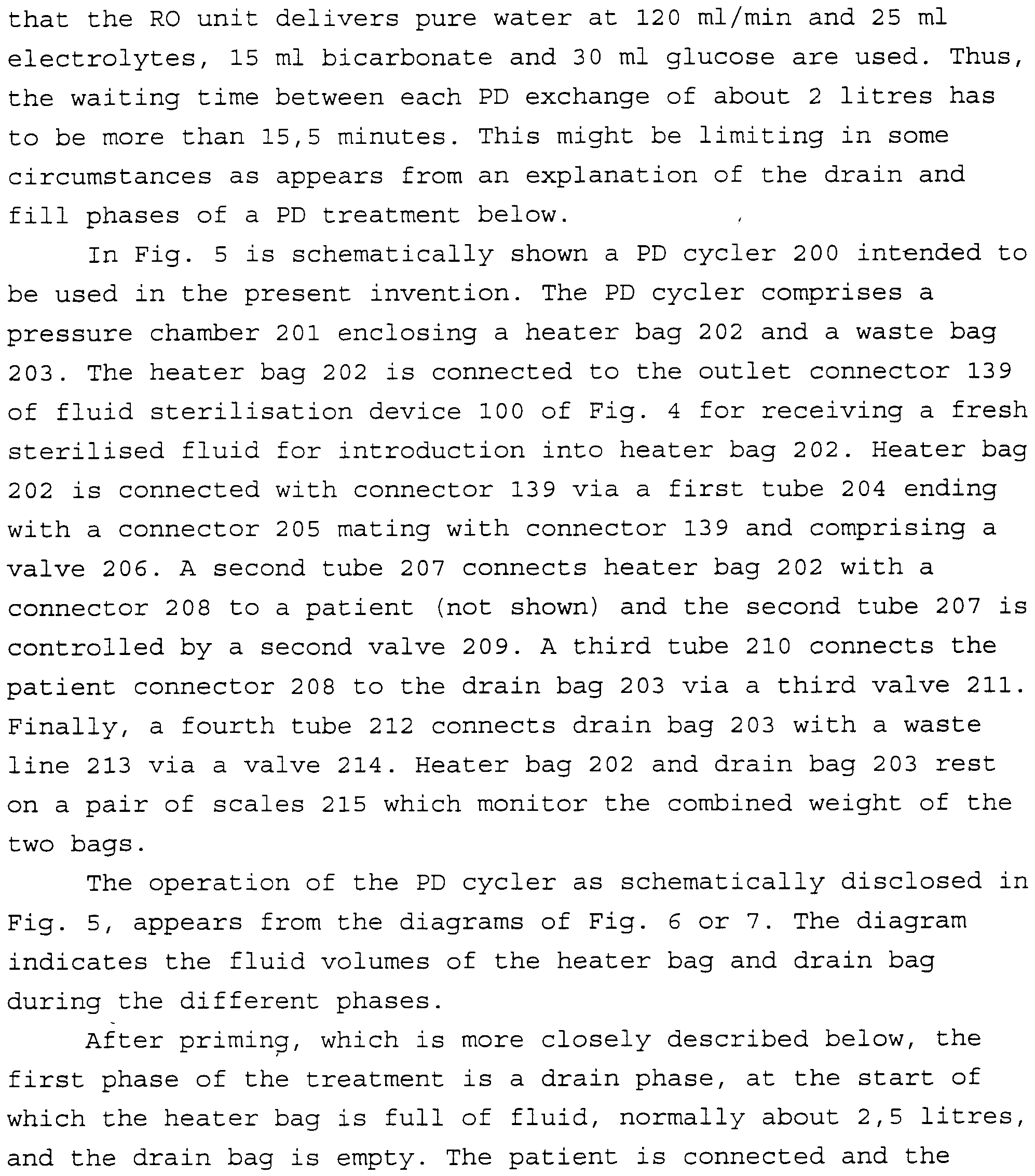
- Fig. 5 is a schematic view of a first embodiment of a cycler which may be connected to the device according to Fig. 2, 3 or 4.
- Fig. 6 is a time diagram of the fluid flows in the cycler according to Fig. 5.
- Fig. 7 is an alternative time diagram similar to Fig. 6.
- Fig. 8 is a schematic view similar to Fig. 5 of a second embodiment of the cycler.
- the fluid to be sterilised comprises a first non-heat- sensitive portion and a second heat sensitive portion.
- the two portions may be delivered separately to the sterilising device into two separate inlets 1 and 2.
- the first non-heat-sensitive component which may comprise sodium chloride dissolved in water
- the second heat sensitive component which may comprise glucose
- the fluid components are preferably provided at a temperature at which each component is relatively stable, such as room temperature.
- the first fluid portion from vessel 3 provided to inlet 1 is impelled by a first pump 5 to a heater 6, in which the first fluid portion is heated to a first high temperature.
- the second fluid portion is impelled by a second pump 7 and mixed with the first fluid portion in a mixing point 8 arranged downstream of the heater 6.
- the mixing the second fluid portion is rapidly heated to a sterilising temperature, while the first fluid portion is cooled to the same sterilising temperature.
- the second fluid portion does not make direct contact with the heater surface and so damage is minimised.
- flow mixing means may be arranged in the flow path, such as at the mixing point 8 or in the flow path downstream of mixing point 8.
- Such flow mixing means may be flanges or wings in the flow path.
- the mixed fluid portions pass through a sterilising tube section 9 dimensioned to provide a predetermined resident or sterilising time for the mixed fluids at the sterilising temperature.
- the tube section may be insulated as indicated by box 10 to maintain the mixed fluids at the sterilising temperature for the sterilising time.
- the mixed fluids are sterile, since the second fluid portion has been subjected to the sterilising temperature during a sterilising time and the first fluid portion has been exposed to a still higher temperature and still longer time, thus being oversterilised.
- the sterilising dose is a function of temperature and time and is defined according to the formula:
- a sterilisation dose of 20 minutes is obtained. If the sterilising temperature is 141 °C and the time ⁇ _s 12 seconds, a sterilisation dose F 0 of 20 minutes is also obtained. A sterilising dose F 0 of 20 minutes is considered sufficient, however, m certain applications, a sterilising dose F 0 of 10 minutes or even lower may be sufficient .
- the first fluid portion may comprise sodium chloride at a concentration of 150 mM, sodium lactate at a concentration of 38,8 mM, magnesium chloride at a concentration of 0,56 mM and calcium chloride at a concentration of 1,89 mM.
- the second fluid portion may comprise glucose at a concentration of 40%, i.e. 400 g glucose per litre solution.
- the first fluid portion flow rate is 45 ml/mm and the second fluid portion flow rate is 5 ml/mm.
- the resulting mixture has the following composition: sodium chloride 135 mM, sodium lactate 35 mM, magnesium chloride 0,5 mM, calcium chloride 1,7 mM and glucose 4%.
- the first fluid portion is heated from 20°C to 155°C by the heater 6.
- the second fluid portion is heated from 20°C to 141°C during mixing, while the first fluid portion is cooled from 155°C to 141°C.
- the resident or sterilising time is 12 seconds resulting m a sterilising dose F 0 of 20 minutes.
- the resulting sterilised fluid mixture is cooled by a cooler 13 and delivered to an outlet 11 and collected in a vessel 12.
- a pump 20 or other device may be arranged to control the flow to the vessel 12.
- the sterile fluid may be used as a peritoneal dialysis solution to be delivered to the peritoneal cavity of a patient.
- Other medical fluids may be produced by the device according to the invention, such as hemodialysis solutions, infusion solutions used m hemodiaflltration or hemoflltration, replacement fluids for infusion in the blood, wound irrigation solutions, rinsing solutions etc.
- nutrition solutions often comprises ammo acids, which are heat sensitive, and glucose, which is heat sensitive, and cannot be sterilised together with ammo acids.
- Certain drugs such as msulm, may be produced or included a fluid administered to a patient, and the drug component may be heat sensitive.
- Certain medical fluids comprise peptides, proteins or fragments thereof, which normally are heat sensitive.
- Preservation fluids for blood component handling may also comprise heat sensitive components, at least glucose.
- glucose is replaced with or complemented with glucose polymers, di-sacha ⁇ des , t ⁇ -sacharides etc.
- Certain carboxylic acids are heat sensitive and may be included m such fluids. Solutions comprising calcium or magnesium ions and carbonate or bicarbonate ions may precipitate at exposure to a sterilising temperature, and need to be sterilised with the carbonate or bicarbonate separate from the calcium or magnesium containing solution.
- a first temperature sensor 14 may be arranged immediately downstream of the heater 6 to determine the temperature of the first fluid portion after heating.
- a second temperature sensor 15 may be arranged between the second inlet 2 and the mixing point 8 to determine the temperature of the second fluid before mixing.
- a third temperature sensor 16 may be arranged downstream of the mixing point to determine the mixing temperature .
- a fourth temperature sensor may be arranged downstream of the sterilising section 9 to determine the sterilising temperature.
- a fifth temperature sensor 18 may be arranged downstream of cooler 13 to determine the temperature of the fluid delivered to vessel 12. Not all of these five temperature sensors are needed so one or several thereof may be excluded.
- a control processor 19 may be arranged to control the sterilising device according to the invention. As shown m Fig. 1, the five temperature sensors are connected to the processor as well as the pumps 5, 7 and 20 to provide measurements of the temperatures and flow rates.
- the pumps 5, 7 and 20 may be volumetric pumps also acting as flow meters. Alternatively, separate flow meters may be provided.
- the processor controls the heater 6 to provide the required temperature downstream of the heater, as measured by temperature sensor 14, to provide the sterilising temperature after mixing as measured by temperature sensors 16 and 17.
- the processor calculates the residence time m the sterilising section 9 based on the flow rates of pumps 5 and 7 and the known volume of the sterilising section 9. Finally, the processor may determine the obtained sterilising dose F 0 .
- the control processor 19 may obtain all necessary information m order to calculate the sterilising effect from the flow rates of pumps 5 and 7 and the temperature of sensor 17.
- the fluids provided to inlets 1 and 2 may be preheated by preheaters 21 and/or 22.
- a high pressure zone m the pipes or lines between pumps 5, 7 and 20.
- glucose decomposes when exposed to heat, and is thus a heat sensitive component of the fluid.
- Glucose also decomposes during storage. It is known that several factors influence the decomposition of glucose, among which are pH, temperature, time, glucose concentration and mixing with certain ionic components. Glucose decomposes into components, some of which may be more or less toxic or are able to induce toxic reactions by including precursors for such reactions. If the resulting fluid is to be used as a medical fluid for infusion into a human being or other mammal, the toxic components or precursors should be minimised.
- the concentration may be above 15% or above 20% with 40% - 50% being preferred, calculated as weight of glucose per litre solution.
- the sterilisation may take place during a short time and at a pH of below about 5,5 and at a dilution concentration. It is believed that the short time is of greater importance than the other factors for avoiding decomposition into toxic components of glucose during the sterilisation process.
- glucose may decompose into precursors for AGE, advanced glucosylation end products.
- a glucose solution comprising precursors for AGE contacts proteins in the body, a non-enzymatic reaction takes place resulting in
- the sterilising device according to the invention is integrated in a PD monitor arranged to provide a PD solution to a patient.
- the PD solution is prepared from two concentrates provided in two concentrate bags 51 and 52 and connected to concentrate input connectors 56 and 57, and a supply of pure water, for example provided from a reverse osmosis RO- unit 53 connected to a water input connector 58 for connection to a potable water supply.
- the sterilised PD fluid is delivered to a PD cycler 55, which is, in turn, connected to a PD fluid output connector 59 for delivery to the patient.
- Each of the three input connectors and the output connector may be arranged as a heat sterilisable connector.
- a heat sterilisable connector device is described in WO 96/05883, which is enclosed in the present specification by reference.
- Each of the inputs 56, 57 and 58 and the output 59 is arranged as a connector device.
- Input 56 is arranged to connect a first concentrate bag 51 to a first metering pump 60 and input 57 is arranged to connect a second concentrate bag 52 to a second metering pump 61.
- Input 58 is connected to RO-unit 53 and a third pump 62 is arranged to pump pure water from RO-unit 53.
- Pumps 62 and 60 are driven to mix the concentrate from bag 51 with pure water from RO-unit 53 to provide a desired concentration.
- a conductivity cell 63 may be arranged to measure the conductivity of the mixture and may control the pump 60 and/or 62 to obtain the required conductivity and thus the desired concentration.
- Pump 62 is preferably driven to provide a constant flow of for example 54 ml/min and at the same time increase the pressure to 3 - 6 Bar absolute pressure to avoid boiling during sterilisation.
- the fluid provided so far is the first heat -insensitive fluid mentioned above.
- the first fluid passes through a first heat exchanger 64 comprising a primary circuit 64a for heating the first fluid, for example from 20°C to 100°C. Then, the first fluid passes through a heater 65 such as an electric heater powered by an electric power supply 66 to heat the first fluid to a temperature of 155°C.
- a heater 65 such as an electric heater powered by an electric power supply 66 to heat the first fluid to a temperature of 155°C.
- the second, heat sensitive, fluid from bag 52 is pumped by pump 61, at a flow rate of 6 ml/min to a mixing point 67 immediately downstream of heater 65 to mix with the first fluid.
- the second fluid is thus rapidly heated from room temperature to a temperature of 141°C by being mixed with the hot first fluid, which at the same time cools down to 141°C.
- the mixed fluids pass through a sterilising unit 68 comprising a tube 68a of a length suitable for providing a residence time giving the required sterilising time, such as 12 seconds.
- the tube is embedded in an insulating .material 68b to minimise the temperature decrease during the residence time.
- a temperature sensor 69 Immediately downstream of the sterilising unit 68 is a temperature sensor 69, which controls the power supply 66 so that the temperature is the desired sterilising temperature, such as 141°C.
- Pump 61 is controlled to deliver the heat sensitive fluid in the amount desired.
- the heat sensitive fluid is glucose at a concentration of 40%
- the flow rate should be 6 ml/min to give a final concentration of 4% if the first flow rate is 54 ml/min.
- the flow rate should be 2,1 ml/min and if a concentration of 2,5% should be obtained, the flow rate should be 3,6 ml/min.
- the temperature sensor adjusts the power supply to heat the first fluid to a suitable temperature so that the sterilising temperature is obtained.
- the now sterilised fluid enters the secondary circuit 64b of the heat exchanger 64 to rapidly decrease the temperature of the sterilised fluid, for example to 60°C. Then, the sterilised fluid passes a flow restrictor 70 to decrease the pressure to close to atmospheric pressure.
- the flow restrictor 70 is controlled by a pressure sensor 71, so that the pressure before the restrictor is the desired pressure to prevent boiling, such as 6 Bar absolute pressure .
- the sterilised fluid is delivered to the output 59, which is connected to a PD cycler 55.
- a pressure relief valve 72 is arranged to connect the sterilised fluid to a waste 73 if the pressure of the fluid exceeds a predetermined value, such as 150 mmHg above atmospheric pressure.
- the PD cycler may be of the type described in WO 95/20985, comprising a pressure chamber.
- a disposable line set is connected between the outlet connector and the patient and comprises a heater bag and a drain bag, a drain line and a supply line.
- the heater bag and a drain bag are arranged on a weighing device, such as a pair of scales .
- Four valves in a valve unit are arranged to operate on the drain and supply lines.
- the line set comprises a PD patient connector for connection to a catheter ending in the peritoneal cavity of the patient.
- the PD replenishment fluid from outlet 59 is supplied to the heater bag via the valve unit until the scales indicate that the heater bag has been replenished to a predetermined volume, such as 3 litres.
- the patient is drained by exposing the pressure chamber to a subpressure to withdraw fluid in the peritoneal cavity of the patient out via the open valve unit into the drain bag.
- the combined weight of heater bag and drain bag is weighed and the drain phase is terminated when it is determined that the drain flow rate is below a predetermined limit or a drain time has elapsed.
- the drain flow rate is determined by means of the weighing device.
- the pressure chamber is exposed to an overpressure and the valve unit is opened to allow the replenished and sterilised PD fluid to flow into the peritoneal cavity of the patient.
- the flow rate and the delivered fluid volume is monitored and the fill phase is terminated when a desired fill volume has been delivered.
- the temperature of the heater bag is controlled by a heating device and temperature sensor so that the fluid delivered has a temperature of about 37°C.
- the drain bag is emptied to a waste receiver by opening the valve unit and exposing the pressure chamber to an overpressure .
- the PD fluid When the patient has been exposed to a fluid exchange as described above, the PD fluid is left in the peritoneal cavity for a dwell time until the next exchange cycle.
- the sterilising device provides new replenishment sterile fluid to the heater bag. It takes about 33 minutes to produce a volume of 2 litres if sterile fluid is produced at 60 ml/mm.
- the cooler may be a Peltier cooler or a heat exchanger of conventional design, using cold water or a cooling medium as heat energy absorption medium.
- a cooler 91 such as a Peltier cooler, may alternatively or additionally be placed after residence device 68 and before heat exchanger 64, m order to rapidly cool the heat sensitive mixture to a safe temperature, such as from 141°C to 120°C.
- the heat sensitive component is heated rapidly from room temperature to sterilisation temperature of 141°C at mixing point 67, is maintained at the sterilising temperature during 12 seconds by residence device 68 and is then rapidly cooled to 120°C by Peltier cooler 91 and then further cooled to room temperature in the slightly slower heat exchanger 64.
- the sterilising device needs to be disinfected at suitable intervals, for example once per day or once per week.
- the side openings of the connector devices 56, 57, 58 and 59 are used.
- the side opening 83 of RO mlet 58 is connected to the side opening 82 of outlet 59 via a line 84.
- the side opening 85 of first mlet 56 is connected to the flow line 86 between RO mlet 58 and the pump 62 via a line 87.
- the side opening 88 of second mlet 57 is connected to the line 89 between heater 65 and sterilising unit 68 via a line 90.
- the sterilising device is filled with pure water obtained from the RO-unit. Then, connectors 57, 58 and 59 are disconnected from the respective sources.
- the RO- let connector 58 and the outlet connector 59 are connected via line 84 and side openings 82 and 83.
- the second mlet connector 57 is in the same position so that a circulating path is obtained via pump 61, line segment 89, line 90, side opening 88 and mlet 57.
- a disinfecting solution is provided m a vessel connected to the first mlet 56.
- the disinfecting fluid may be sodium carbonate, citric acid or any other known disinfection fluid.
- Pumps 62 and 61 are operated to circulate the fluid in the circuits.
- pump 60 is operated to infuse disinfection fluid into the water until a sufficient disinfectant concentration has been obtained. The surplus water is rejected via relief valve 72 to the waste receiver 73.
- Pump 62 circulates the disinfection fluid through the complete sterilisation device and the outlet 59 is connected to the mlet 58 via line 84 to complete the circuit.
- the disinfection fluid may be left in the machine until the next use. Before the next use, the machine is rinsed with pure water via mlet 58 from the source of RO-water.
- Descaling with citric acid or other descaling agent is performed m the same manner .
- the mlet connectors 56, 57 and 58 and the outlet connector 59 are positioned at the highest position of the flow path and at the same level .
- the machine may be emptied by opening all inlets 56, 57 and 58 and the outlet 59 and by opening the relief valve 72, which is positioned at the lowest point of the flow path and allowing air to enter all lines and devices.
- the heater 65 may be turned off or adjusted to heat the fluid to a low temperature.
- the flow restrictor 70 may be opened.
- the fluid m the entire circuit is heated to 121°C and circulated for at least 20 minutes to obtain sterilisation of the entire circuit.
- pressure relief valve 72 is operated to permit a pressure of 2 Bar, thereby preventing boiling of the water m the circuit at 121°C.
- the fluid circuit is arranged for a treatment with all connectors inserted m respective bore m the non-engaged position.
- the circuit is full with water, which is circulated by pump 62.
- Flow restrictor 70 is opened and relief valve 72 is adjusted to a pressure of 2 - 3 Bar absolute pressure.
- First inlet connector 56 is operated to connect the vessel 51 to the circuit.
- pump 60 is operated to introduce some fluid (electrolyte fluid) in the circuit until the pressure reaches about 2 - 3 Bar absolute pressure. Since the fluid circuit is relatively non-compliant , the volume of fluid introduced is small.
- the heater is activated to heat the water present in the circuit to a temperature pf 121°C and the circulation continues for 20 minutes or longer, until sterilisation is obtained.
- Pump 61 is operated simultaneously to sterilise the circuit comprising inlet connector 57.
- RO inlet 58 is activated to connect RO-unit 53 to the circuit and at the same time disconnect bypass line 84.
- Pump 60 is stopped, and heater 65 is activated.
- Flow restrictor 70 is activated and pressure relief valve 72 is adjusted to the normal value of 150 mmHg overpressure.
- the second inlet is activated to connect vessel 52 and pumps 60 and 61 are operated to provide a PD fluid.
- the outlet 59 is activated to deliver sterilised fluid to the heater bag .
- the heat sensitive component may be introduced together with the remaining components, and the bag 52, connector 57 and the corresponding pump 61 can be dispensed of.
- the other components of the fluid may be entered in the same way as component 51, i.e. mixed with water and the remaining components before heat sterilisation.
- the sterilising device may continue to produce PD fluid. However, since the valve unit is closed, the PD fluid produced is directed to the waste receiver 73 via relief valve 72. Since the drain and fill phases may last up to 20 minutes or more, a considerable amount of PD fluid is wasted. To minimise such waste, pumps 60 and 61 may be stopped during the periods when the heater bag is not being filled, and the sterilising device is only producing and wasting sterile water.
- the first and/or second concentrates may comprise the same substances or components as mentioned above, however, with the contents of the first vessel 51 concentrated by omitting some of the water.
- the contents of the first vessel may be concentrated for example 30 - 40 times.
- the PD fluid is intended to comprise bicarbonate instead of or m addition to lactate.
- Calcium cannot be included in the same vessel as bicarbonate, because of the risk of precipitation of calcium carbonate.
- the calcium chloride may be included in the second vessel 52 m a suitable concentration. The calcium concentration will then be proportional to the glucose concentration, which may result m a calcium neutral PD fluid.
- Another advantage of including the calcium ions m the second vessel is that scaling of the pipe system is avoided before the mixing point 67, and the requirement for descaling would decrease.
- Further components may be included into the fluid flow before pump 62, by the inclusion of a further bag 51a, connector 56a and pump 60a, m parallel with vessel 51.
- Each of the sterilisable connectors may be replaced by a conventional connector device and a three way valve of conventional type, as shown m more detail m Fig. 3, which shows an alternative embodiment of the invention.
- Fig. 3 shows an alternative design of a mixing system delivering the mixed fluids m parallel through the residence device.
- Fig. 3 shows only the right-hand portion of Fig. 2 to the right of pump 62 and pressure sensor 70.
- the left-hand portion may be identical to the embodiment of Fig. 2.
- the same components as in Fig. 2 have received the same reference numerals but adding 100 to the reference numbers.
- a heat exchanger 164 comprising a primary circuit 164a and a secondary circuit 164b and a pump device 164c.
- An electrolyte solution or pure water is conducted through line 189 through heat exchanger primary circuit 164a and a second heater 165, for example an electric heater controlled by a temperature sensor 169.
- a first bag 152a comprising a heat sensitive first component such as glucose is connected via a connector 192a to a three-way valve 157a.
- the first component passes from the three-way valve 157a to a pump 161a and further to a mixing point 167a, in which the first component is heated to 141°C by mixture with a heated electrolyte component, having a temperature sufficient for promoting such heating by mixing, the temperature being for example 155°C.
- the mixing temperature is controlled by a temperature sensor 169a, which operates a throttle valve 193a arranged before the mixing point 167a. By throttling the valve 193a, a sufficient flow rate for obtaining said temperature is adjusted.
- a second bag 152b comprising a heat sensitive second component, such as amino acids, is connected via a connector 192b to a three-way valve 157b.
- the second component passes from the three-way valve 157b to a pump 161b and further to a mixing point 167b, in which the second component is heated to 141°C by mixture with a heated electrolyte component, having a temperature sufficient for promoting such heating by mixing, the temperature being for example 155°C.
- the mixing temperature is controlled by a temperature sensor 169b, which operates a throttle valve 193b arranged before the mixing point 167b. By throttling the valve 193b, a sufficient flow rate for obtaining said temperature is adjusted.
- the two heat sensitive components heated to sterilising temperature by mixture with the electrolyte component are handled in parallel in two separate lines 194a and 194b, which pass in parallel through the residence device 168, the pre-cooler 191, if present, and to heat exchanger secondary circuit 164b. After cooling in the heat exchanger, the two fluids are mixed in a Y- connector 195 before entering the restriction device 70, see Fig. 2.
- the bags 152a and 152b are weighed and when a sufficient amount of fluid has been taken out from each bag, valve 157a L J t "! O o (- ⁇ o ⁇ -!
- the connectors 102, 103 and 104 are attached to the ends of flexible tubes of PVC or other suitable pliable material, so that the connectors and tubes do not significantly influence the weight of the assembly.
- the RO let connector 101 is connected to a line system including a first mlet line 109.
- Inlet line 109 is provided with an mlet valve 110, to isolate the device 100 if required.
- Inlet valve 110 is normally closed, but is opened upon activation by a control device 111 shown by broken lines.
- the control device may be a computer or microprocessor or any other control device. Normally, it is the control computer of the complete device.
- Inlet line 109 further comprises a heater 112 and a temperature sensor 113, which operate together to adjust the temperature of incoming pure water to a predetermined temperature of e.g. 25°C, m order to make the device independent of incoming water temperature .
- Inlet line 109 further comprises a flow meter 114 for measuring the complete mlet flow through mlet connector 101, for a purpose to be described later.
- Water line 115 comprises a first pump 117 for increasing the pressure of the water m water line 115 downstream of the pump to a pressure of 2 - 6 Bar absolute pressure.
- the pressure is measured by a first pressure sensor 118 and monitored by a second pressure sensor 119.
- the first pressure sensor 118 is connected to the control system of computer 111, while the second pressure sensor 119 is connected to a parallel supervising system for ensuring the safety of the system.
- Several of the sensors are duplicated m this manner to provide independent data to the supervisory system or processor, even if not explicitly indicated in the drawings.
- Water line 115 further comprises a valve 120 and a primary circuit of a heat exchanger 121.
- the water m water line 115 is heated from about 25°C to about 131°C in heat exchanger 121, at a flow of about 120 ml/min.
- the temperature of the heated water is monitored by temperature sensor 122.
- water line 115 comprises a second heater 123, for heating the water to a still higher temperature, such as about 145°C.
- the hot water is delivered to a mixing point 124.
- concentrate line 116 there is a valve 125 for connecting the normally closed concentrate line 116 to water line 115. Further downstream, concentrate line 116 comprises three concentrate valves 126, 127 and 128 and a reversible second pump 129.
- the second pump 129 is arranged to withdraw concentrate solutions or fluids from any one of concentrate bags 105, 106 or 107 depending on the positions of valves 126, 127 and 128. The second pump 129 further increases the pressure of the fluid in concentrate line 116 to a pressure of 2 - 6 Bar absolute pressure.
- Second pump 129 Downstream of second pump 129 is arranged a valve 130, and therefrom, the concentrate fluid is delivered to a second primary circuit of heat exchanger 121 in order to preheat the concentrate solution from e.g. room temperature to about 131°C. From heat exchanger 121, the concentrate solution is delivered to mixing point 124.
- a temperature sensor 131 for measuring the temperature of the incoming concentrate fluid
- a pressure sensor 132 for measuring that sufficient pressure has been obtained.
- these sensors may be duplicated for supervisory purposes.
- Mixed fluid line 133 comprises a residence device 134, normally being a length of tube of a length to produce a predetermined residence time at a predetermined rate of flow to effect sterilisation of the fluid in the residence device 134.
- the residence device 134 is preceded by a temperature sensor 135 and followed by a temperature sensor 136. These temperature sensors control the heater 123 to ensure that sterilising conditions are obtained m the residence device 134, such as a minimum temperature of 141°C for 12 seconds.
- the sterilised and mixed fluid is passed to the secondary circuit of heat exchanger 121, at a temperature of approximately 141°C. The sterilised fluid is rapidly cooled to about 37°C.
- mixed fluid line 133 Downstream of the heat exchanger, mixed fluid line 133 comprises sterilised fluid at a temperature suitable to be delivered to a patient or a storage bag. The temperature is monitored by a temperature sensor 137. Finally, a valve 138 directs, when activated, the fluid to an outlet connector 139, via a restrictor device 140, for lowering the pressure to atmospheric pressure.
- the restrictor device may be a small hole in a piece of metal, the hole being dimensioned to reduce the pressure from 6 Bar to 1 Bar at the desired flow rate of, for example, 140 ml/mm.
- An alternative design would be to use a controllable throttle valve, which is controlled by the processor in dependence of pressure sensor readings.
- a third alternative would be to use a throttle device or the pressure relief type, which adjust the differential pressure over the throttle device to a predetermined pressure drop of, for example, 5 Bar.
- a fourth alternative would be to use a throttle device controlled to deliver fluid at an output pressure of no more than a predetermined safe pressure of, for example, 1.25 Bar, in which case the pumps are operated to ensure that the pressure before the throttle device is sufficiently high, for example 6 Bar.
- the on- line autoclave as described is always operated at a predetermined minimal flow rate of not less than a predetermined flow rate, for example 120 ml/mm, in order to ensure that the autoclave is maintained sterile. As soon as the flow rate drops below said predetermined minimum flow rate, the sterility conditions may be hampered or the autoclave may not be controlled to operate at proper temperatures.
- the autoclave may be designed to operate at different flow rates above said minimum flow rate. In order to always maintain a minimal flow rate, any excess fluid produced may be sacrificed to the waste. If the mixed and sterilised fluid cannot be delivered out via the output connector 139, a valve 141 is activated to deliver the fluid to a waste receiver via a waste line 142. Waste line
- 142 further comprises a primary circuit of a s ⁇ cond heat exchanger 143, a pressure sensor 144, a restrictor device 145 and a valve 146 until the fluid is delivered to the waste receiver
- a temperature sensor 148 arranged upstream of heat exchanger
- Fig. 4 may be operated in different modes. One mode of operation will be described below, namely sequential delivery of the components of the final fluid. It is, however, understood that the device may operate as described in connection with Fig. 2 as well.
- water is first delivered in inlet line 109 at a constant rate of 120 ml/min from inlet connector 101, via flow meter 114, in which the flow rate is monitored, and via water line 115 and via first pump 117 to raise the pressure so that the boiling temperature of the fluid is above the temperature anywhere in the circuit.
- the pressure should be above 4.8 Bar or preferably about 6 Bar absolute pressure. The exact pressure is dependent on the adjustment and operation of restriction device 140.
- the water further passes the mixing point 124 and enters the mixed fluid line 133 and reaches valve 138, which directs the flow to waste line 142, via valve 141 and further to the sump.
- the outlet connector 139 is connected to a recipient, normally a bag, such as a heater bag described below. When all conditions are checked and the device delivers sterilised water, valve 138 is switched to direct the sterilised water to the outlet connector 139 via restrictor 140.
- valve 127 in concentrate line 116 is opened and concentrate pump 129 is activated, with valve 130 in an open condition, to pump concentrate fluid from electrolyte bag 106, via heat exchanger 121 to mixing point 124.
- the concentrate pump 130 is operated to provide a flow rate of approximately 20 ml/min.
- the weight of the concentrate assembly is monitored by weighing device 108.
- the flow is continued for about 1 minute and 15 seconds, until the weighing device indicate that a volume of 25 ml has left the bag 106, whereby 25 ml is the amount required from concentrate bag in 1 litre of final fluid (1:40) .
- valve 127 is switched off and valve 125 is opened for a short time, such as 15 seconds, to rinse the concentrate line 116.
- the second concentrate which may be glucose
- bag 107 is connected to the concentrate pump by closing valve 125 and opening valve 128. If the glucose concentrate fluid has a concentration of 50%, the concentrate pump is driven 1 minute per percent concentration to be required in the final fluid at 20 ml/min. If 4% is required, which is the maximum contemplated for a PD fluid, the glucose concentrate is dosed in 4 minutes.
- the concentrate line 116 is again rinsed with water, for example for 15 seconds.
- the bicarbonate bag 105 is connected.
- the bicarbonate is normally stored at a concentration of about 1000 mmol/1.
- valve 125 is closed and valve 126 is opened so that concentrate pump 130 pumps bicarbonate fluid out of bag 105.
- the flow rate may be the same, 20 ml/min, and the mixing and sterilisation of bicarbonate fluid is discontinued when the weighing device determines that the required quantity has been removed from bag 105. If the final solution should contain 15 mmol/1, the concentrate pump is operated for 45 seconds to take 15 ml of concentrated bicarbonate solution out of bag 105.
- the concentrate line is rinsed once again and water is delivered to the outlet connector, until the final volume of fluid has been delivered to the bag connected at the outlet connector, which is determined by flow meter 114 m combination with the weight losses measured by weighing device 108 and calculated into volumes by computer 111, taking into account the different densities of the concentrate fluids.
- This final filling of water also means that the mix of fluid in the bag connected to the outlet connector is agitated and mixed thoroughly.
- valves 138 and 141 are maintained m the same position directing all fluid to the outlet connector 139.
- all fluid produced is delivered to the receiver, thereby minimising the time required for the preparation of the complete fluid.
- the concentrate fluid bags may include concentrate fluid required for a final fluid volume of 12 - 25 litres or more if required. Then, the above sequence is repeated for each batch of 2 litres to prepare.
- bicarbonate is not used, but lactate is used as the sole buffer.
- the third bag in the concentrate assembly is unnecessary, and only two bags may be used. In that case, valve 126 is always closed. OJ OJ to to
- the drain phase is terminated.
- the drain phase is normally 7 - 10 minutes.
- the second phase is a fill phase, in which the peritoneal cavity of the patient is filled with fresh fluid contained in heater bag 202. An overpressure is exerted in pressure chamber 201 and valve 209 is opened, while the other valves are c-losed.
- the fill flow rate depends on the patient and the overpressure and may be 150 ml/min.
- the fill phase is normally 10 - 15 minutes .
- the third phase is an empty drain bag phase, in which an overpressure is exerted in the pressure chamber 201 and valve 214 is open.
- the fluid in the drain bag is directed to a waste line 213.
- the volumes are always monitored by the scales 215.
- the third phase may be about 2 minutes, since a high overpressure may be used and the flow restriction is minimal.
- the fourth phase is heater bag replenishment phase with valve 206 open.
- a subpressure is exerted in the pressure chamber 201.
- Fluid is received from the sterilising device 100 connected to connector 205 at a flow rate of about 120 ml/min.
- the fourth phase is normally 15 - 17 minutes .
- a complete cycle is 34 - 44 minutes.
- the emptying phase and the replenishment phase may be interchanged. If it is desired to increase the fluid volume further, the times in the different phases have to be shortened. It is noted that the heater bag fill time of 15 - 17 minutes could be shortened by increasing the flow rate of fluid from steriliser 100. However, increasing the flow rate means considerable cost increases . Instead it is noted that the flow rate of the fluid delivered from steriliser 100 is monitored by the steriliser by flow meter 114 and weighing device 108. Thus, it is possible to replenish the heater bag during (part of) the drain cycle as shown in Figs. 6 and 7. This is done by opening valve 211 while valve 209 is closed during the heater bag replenishment phase.
- the drain phase is terminated before the heater bag is replenished, the patient fill phase cannot start until the heater bag replenishment is completed. However, it is no drawback to continue the drain phase longer, since that only results in some further fluid being drained, which normally is an advantage. Since the replenishment flow from the steriliser is known, the PD cycler still has full control of the flows by using the reading from the scales and subtracting the replenishment flow obtained from the steriliser. In this way, almost the complete drain phase can be saved in the cycle time, i.e. up to 10 minutes.
- Fig.6 the normal cycle time is shown by arrow 216 while the shortened cycle time according to the invention is shown by arrow 217.
- Fig. 7 the normal cycle time is shown by arrow 218 while the reduced time according to the invention is shown by arrow 219.
- the two cases of Figs. 6 and 7 becomes the same according to the present invention, see arrows 217 and 219.
- Fig. 7 it is shown that the replenishment phase starts immediately after the fill phase. However, it is understood that it can start any time during the emptying phase or the following drain phase. However, by starting the replenishment phase as soon as possible, longer time is obtained for heating the replenishment fluid to 37 degrees Celsius.
- Figs. 6 and 7 the pressure in the pressure chamber is indicated at the bottom by "neg" and "pos", indicating a subpressure or an overpressure. Since the replenishment phase does not need a negative pressure, there is only one positive period and one negative period of pressure in a cycle, compared to two of each in the normal cycle of Fig. 7. This will result in a saving of the power required for the air pump in the cycler and a reduction of the sound level.
- the replenishment takes place by means of the volumetric pump and overpressure in the autoclave, possibly monitored by a flow meter, such as flow meter 220 shown in Fig. 5.
- Fig. 8 the same components as in Fig. 5 have received the same reference numeral starting with 3 instead of 2.
- the inlet tube 304 is provided with a branch line 316 ending in a storage bag 317.
- valve 306 When valve 306 is closed during the first, second and third phase, the steriliser 100 delivers PD solution into storage bag 317 via tube 316.
- the heater bag 302 may then be replenished much faster from the storage bag 317 compared to the embodiment of Fig. 5.
- the heater bag replenishment phase may be reduced to 2 minutes or less.
- the efficiency of the complete device becomes dependent only on the cycler and its capacity to drain and fill the patient. The surplus time is merely 4 minutes, 2 minutes for emptying of the drain bag and 2 minutes for replenishment of the heater bag.
- the procedure has to be controlled if the steriliser is operated in the sequential mode as described in connection with Fig. 4, since the filling of heater bag has to start only when the concentrations are correct in storage bag 317, i.e. after the completion of an entire fill cycle from the steriliser.
Landscapes
- Health & Medical Sciences (AREA)
- Life Sciences & Earth Sciences (AREA)
- Animal Behavior & Ethology (AREA)
- General Health & Medical Sciences (AREA)
- Public Health (AREA)
- Veterinary Medicine (AREA)
- Epidemiology (AREA)
- Engineering & Computer Science (AREA)
- Biomedical Technology (AREA)
- Chemical & Material Sciences (AREA)
- Medicinal Chemistry (AREA)
- Molecular Biology (AREA)
- Emergency Medicine (AREA)
- Urology & Nephrology (AREA)
- Heart & Thoracic Surgery (AREA)
- Vascular Medicine (AREA)
- Anesthesiology (AREA)
- Hematology (AREA)
- External Artificial Organs (AREA)
- Apparatus For Disinfection Or Sterilisation (AREA)
- Medicinal Preparation (AREA)
- Pharmaceuticals Containing Other Organic And Inorganic Compounds (AREA)
- Medicines Containing Material From Animals Or Micro-Organisms (AREA)
- Acyclic And Carbocyclic Compounds In Medicinal Compositions (AREA)
Abstract
Description


Claims
Priority Applications (5)
| Application Number | Priority Date | Filing Date | Title |
|---|---|---|---|
| AU75674/00A AU7567400A (en) | 1999-09-16 | 2000-09-14 | Method and cycler for peritoneal dialysis |
| KR1020027003226A KR20020026385A (en) | 1999-09-16 | 2000-09-14 | Method and cycler for peritoneal dialysis |
| EP00964850A EP1216069A1 (en) | 1999-09-16 | 2000-09-14 | Method and cycler for peritoneal dialysis |
| JP2001523058A JP2003509131A (en) | 1999-09-16 | 2000-09-14 | Peritoneal dialysis method and circulation device therefor |
| HK02108359.6A HK1046651A1 (en) | 1999-09-16 | 2002-11-19 | Method and cycler for peritoneal dialysis |
Applications Claiming Priority (2)
| Application Number | Priority Date | Filing Date | Title |
|---|---|---|---|
| SE9903331A SE9903331D0 (en) | 1999-09-16 | 1999-09-16 | Method and apparatus for sterilizing a heat sensitive fluid |
| SE9903331-8 | 1999-09-16 |
Related Child Applications (2)
| Application Number | Title | Priority Date | Filing Date |
|---|---|---|---|
| US10088195 A-371-Of-International | 2002-07-16 | ||
| US10/746,670 Division US20040215129A1 (en) | 1999-09-16 | 2003-12-22 | Method and cycler for the administration of a peritoneal dialysis fluid |
Publications (1)
| Publication Number | Publication Date |
|---|---|
| WO2001019430A1 true WO2001019430A1 (en) | 2001-03-22 |
Family
ID=20417030
Family Applications (2)
| Application Number | Title | Priority Date | Filing Date |
|---|---|---|---|
| PCT/SE2000/000630 WO2001019413A1 (en) | 1999-09-16 | 2000-04-04 | Method and apparatus for producing a sterile fluid |
| PCT/SE2000/001772 WO2001019430A1 (en) | 1999-09-16 | 2000-09-14 | Method and cycler for peritoneal dialysis |
Family Applications Before (1)
| Application Number | Title | Priority Date | Filing Date |
|---|---|---|---|
| PCT/SE2000/000630 WO2001019413A1 (en) | 1999-09-16 | 2000-04-04 | Method and apparatus for producing a sterile fluid |
Country Status (9)
| Country | Link |
|---|---|
| US (1) | US6967002B1 (en) |
| EP (2) | EP1221981A1 (en) |
| JP (2) | JP2003509126A (en) |
| KR (2) | KR20020043586A (en) |
| AU (2) | AU779754B2 (en) |
| CA (1) | CA2383923A1 (en) |
| HK (1) | HK1046651A1 (en) |
| SE (1) | SE9903331D0 (en) |
| WO (2) | WO2001019413A1 (en) |
Cited By (41)
| Publication number | Priority date | Publication date | Assignee | Title |
|---|---|---|---|---|
| US7964766B2 (en) | 2003-10-28 | 2011-06-21 | Smith & Nephew Plc | Wound cleansing apparatus in-situ |
| US8282611B2 (en) | 2004-04-05 | 2012-10-09 | Bluesky Medical Group, Inc. | Reduced pressure wound treatment system |
| US20120279910A1 (en) * | 2009-06-15 | 2012-11-08 | Mark Wallace | Dialysis Machine |
| US8449509B2 (en) | 2004-04-05 | 2013-05-28 | Bluesky Medical Group Incorporated | Flexible reduced pressure treatment appliance |
| US8460255B2 (en) | 2006-05-11 | 2013-06-11 | Kalypto Medical, Inc. | Device and method for wound therapy |
| US8500676B2 (en) | 2003-10-13 | 2013-08-06 | Fresenius Medical Care Deutschland Gmbh | Device for carrying out a peritoneal dialysis treatment |
| US8545464B2 (en) | 2002-09-03 | 2013-10-01 | Bluesky Medical Group Incorporated | Reduced pressure treatment system |
| US8585634B2 (en) | 2003-07-31 | 2013-11-19 | Debiotech S.A. | System for performing peritoneal dialysis |
| US8663198B2 (en) | 2009-04-17 | 2014-03-04 | Kalypto Medical, Inc. | Negative pressure wound therapy device |
| US8715256B2 (en) | 2007-11-21 | 2014-05-06 | Smith & Nephew Plc | Vacuum assisted wound dressing |
| US8764732B2 (en) | 2007-11-21 | 2014-07-01 | Smith & Nephew Plc | Wound dressing |
| US8795243B2 (en) | 2004-05-21 | 2014-08-05 | Bluesky Medical Group Incorporated | Flexible reduced pressure treatment appliance |
| US8808274B2 (en) | 2007-11-21 | 2014-08-19 | Smith & Nephew Plc | Wound dressing |
| US8834451B2 (en) | 2002-10-28 | 2014-09-16 | Smith & Nephew Plc | In-situ wound cleansing apparatus |
| US8945074B2 (en) | 2011-05-24 | 2015-02-03 | Kalypto Medical, Inc. | Device with controller and pump modules for providing negative pressure for wound therapy |
| US9058634B2 (en) | 2011-05-24 | 2015-06-16 | Kalypto Medical, Inc. | Method for providing a negative pressure wound therapy pump device |
| US9061095B2 (en) | 2010-04-27 | 2015-06-23 | Smith & Nephew Plc | Wound dressing and method of use |
| US9067003B2 (en) | 2011-05-26 | 2015-06-30 | Kalypto Medical, Inc. | Method for providing negative pressure to a negative pressure wound therapy bandage |
| US9302037B2 (en) | 2007-02-27 | 2016-04-05 | Deka Products Limited Partnership | Hemodialysis systems and methods |
| US9492326B2 (en) | 2004-04-05 | 2016-11-15 | Bluesky Medical Group Incorporated | Reduced pressure wound treatment system |
| US9535021B2 (en) | 2007-02-27 | 2017-01-03 | Deka Products Limited Partnership | Sensor apparatus systems, devices and methods |
| US9539379B2 (en) | 2007-02-27 | 2017-01-10 | Deka Products Limited Partnership | Enclosure for a portable hemodialysis system |
| US9561318B2 (en) | 2002-04-11 | 2017-02-07 | Deka Products Limited Partnership | System and method for delivering a target volume of fluid |
| US9593679B2 (en) | 1999-07-20 | 2017-03-14 | Deka Products Limited Partnership | Fluid pumping apparatus for use with a removable fluid pumping cartridge |
| US9597442B2 (en) | 2007-02-27 | 2017-03-21 | Deka Products Limited Partnership | Air trap for a medical infusion device |
| US9603985B2 (en) | 2007-02-27 | 2017-03-28 | Deka Products Limited Partnership | Blood treatment systems and methods |
| US9724458B2 (en) | 2011-05-24 | 2017-08-08 | Deka Products Limited Partnership | Hemodialysis system |
| US9839775B2 (en) | 2008-01-23 | 2017-12-12 | Deka Products Limited Partnership | Disposable components for fluid line autoconnect systems and methods |
| US9861732B2 (en) | 2011-11-04 | 2018-01-09 | Deka Products Limited Partnership | Medical treatment system and methods using a plurality of fluid lines |
| US9987407B2 (en) | 2007-02-27 | 2018-06-05 | Deka Products Limited Partnership | Blood circuit assembly for a hemodialysis system |
| US10058642B2 (en) | 2004-04-05 | 2018-08-28 | Bluesky Medical Group Incorporated | Reduced pressure treatment system |
| US10058694B2 (en) | 2014-06-05 | 2018-08-28 | Deka Products Limited Partnership | Medical treatment system and methods using a plurality of fluid lines |
| US10098996B2 (en) | 2010-07-07 | 2018-10-16 | Deka Products Limited Partnership | Medical treatment system and methods using a plurality of fluid lines |
| US10195330B2 (en) | 2008-01-23 | 2019-02-05 | Deka Products Limited Partnership | Medical treatment system and methods using a plurality of fluid lines |
| US10201644B2 (en) | 2005-09-07 | 2019-02-12 | Smith & Nephew, Inc. | Self contained wound dressing with micropump |
| US10201647B2 (en) | 2008-01-23 | 2019-02-12 | Deka Products Limited Partnership | Medical treatment system and methods using a plurality of fluid lines |
| EP3466460A1 (en) * | 2017-10-03 | 2019-04-10 | Medtronic Inc. | Peritoneal dialysate temperature regulation system |
| US10441697B2 (en) | 2007-02-27 | 2019-10-15 | Deka Products Limited Partnership | Modular assembly for a portable hemodialysis system |
| US11103625B2 (en) | 2011-05-24 | 2021-08-31 | Deka Products Limited Partnership | Blood treatment systems and methods |
| US11598329B2 (en) | 2018-03-30 | 2023-03-07 | Deka Products Limited Partnership | Liquid pumping cassettes and associated pressure distribution manifold and related methods |
| US11833281B2 (en) | 2008-01-23 | 2023-12-05 | Deka Products Limited Partnership | Pump cassette and methods for use in medical treatment system using a plurality of fluid lines |
Families Citing this family (23)
| Publication number | Priority date | Publication date | Assignee | Title |
|---|---|---|---|---|
| WO2005035023A1 (en) * | 2003-10-13 | 2005-04-21 | Gambro Lundia Ab | A device for carrying out a peritoneal dialysis treatment |
| JP2006174988A (en) * | 2004-12-22 | 2006-07-06 | Jms Co Ltd | Package of medical system and its thermal sterilization method |
| JP2006238915A (en) * | 2005-02-28 | 2006-09-14 | Terumo Corp | Peritoneal dialysis apparatus and method and program for controlling the same |
| JP5204996B2 (en) * | 2006-06-22 | 2013-06-05 | 日機装株式会社 | Dialysis treatment system and its disinfection method |
| KR100985384B1 (en) * | 2008-06-27 | 2010-10-05 | 주식회사 경동네트웍 | Method for controlling a hot water temperature in using low flux in hot water supply system |
| US8753515B2 (en) | 2009-12-05 | 2014-06-17 | Home Dialysis Plus, Ltd. | Dialysis system with ultrafiltration control |
| US8501009B2 (en) | 2010-06-07 | 2013-08-06 | State Of Oregon Acting By And Through The State Board Of Higher Education On Behalf Of Oregon State University | Fluid purification system |
| EP3542840B1 (en) | 2011-03-23 | 2023-04-26 | NxStage Medical, Inc. | Peritoneal dialysis systems |
| WO2013052680A2 (en) | 2011-10-07 | 2013-04-11 | Home Dialysis Plus, Ltd. | Heat exchange fluid purification for dialysis system |
| GB201305755D0 (en) | 2013-03-28 | 2013-05-15 | Quanta Fluid Solutions Ltd | Re-Use of a Hemodialysis Cartridge |
| CN103990194B (en) * | 2014-04-29 | 2016-06-15 | 昆山韦睿医疗科技有限公司 | A kind of dialysate temperature monitoring method, device and peritoneal dialysis instrument |
| WO2015168280A1 (en) | 2014-04-29 | 2015-11-05 | Outset Medical, Inc. | Dialysis system and methods |
| GB201409796D0 (en) * | 2014-06-02 | 2014-07-16 | Quanta Fluid Solutions Ltd | Method of heat sanitization of a haemodialysis water circuit using a calculated dose |
| EP3220975B1 (en) * | 2014-11-21 | 2024-01-24 | Triomed AB | Apparatus for performing peritoneal ultrafiltration |
| GB201523104D0 (en) | 2015-12-30 | 2016-02-10 | Quanta Fluid Solutions Ltd | Dialysis machine |
| EP4289437A2 (en) | 2016-05-06 | 2023-12-13 | Gambro Lundia AB | System for proportioning fluids |
| EP3500317B1 (en) | 2016-08-19 | 2022-02-23 | Outset Medical, Inc. | Peritoneal dialysis system and methods |
| US20190298761A1 (en) | 2016-12-15 | 2019-10-03 | Adept Water Technologies A/S | Device for producing aqueous liquid having free available chlorine (fac) |
| GB201622119D0 (en) | 2016-12-23 | 2017-02-08 | Quanta Dialysis Tech Ltd | Improved valve leak detection system |
| GB201703048D0 (en) | 2017-02-24 | 2017-04-12 | Quanta Dialysis Tech Ltd | Testing rotor engagement of a rotary peristaltic pump |
| CA3068618A1 (en) * | 2017-06-30 | 2019-01-03 | FUJIFILM Irvine Scientific, Inc. | Automated method and apparatus for preparing bioprocess solutions |
| WO2019169081A2 (en) | 2018-02-28 | 2019-09-06 | Nxstage Medical, Inc. | Fluid preparation and treatment devices, methods, and systems |
| JP7135692B2 (en) | 2018-10-05 | 2022-09-13 | ニプロ株式会社 | drainage system |
Citations (5)
| Publication number | Priority date | Publication date | Assignee | Title |
|---|---|---|---|---|
| US4096859A (en) * | 1977-04-04 | 1978-06-27 | Agarwal Mahesh C | Apparatus for peritoneal dialysis |
| US4240408A (en) * | 1977-12-10 | 1980-12-23 | Dr. Eduard Fresenius Chemisch-Pharmazeutische Industrie Kg, Apparatebau Kg | Peritoneal dialysis apparatus |
| EP0097432A2 (en) * | 1982-06-18 | 1984-01-04 | Joseph E. Dadson | Apparatus for peritoneal dialysis |
| EP0112104A2 (en) * | 1982-12-10 | 1984-06-27 | Japan Medical Supply Co., Ltd. | Apparatus for peritoneal dialysis |
| WO1995020985A1 (en) * | 1994-02-03 | 1995-08-10 | Gambro Ab | Apparatus for carrying out peritoneal dialyses |
Family Cites Families (14)
| Publication number | Priority date | Publication date | Assignee | Title |
|---|---|---|---|---|
| GB1450030A (en) | 1972-06-08 | 1976-09-22 | Gow J G | Production of solutions |
| GB1504334A (en) | 1975-04-09 | 1978-03-22 | Ingerthorpe Holdings Ltd | Production of solutions |
| GB2034584A (en) | 1978-11-22 | 1980-06-11 | Surgical Implant Eng | Production of sterile solutions |
| SE500294C2 (en) | 1989-11-16 | 1994-05-30 | Gambro Ab | Set the respective system for the preparation of a sterile dialysis fluid |
| US5032265A (en) | 1990-06-20 | 1991-07-16 | Millipore Corporation | Method and system for producing sterile aqueous solutions |
| SE9103395D0 (en) | 1991-11-18 | 1991-11-18 | Gambro Ab | SYSTEM USING ENSTERIL MEDICAL SOLUTION CONTAINING GLUCOSE OR GLUCOSE-LIKE SUBSTANCES AND A SOLUTION INTENDED FOR THIS SYSTEM |
| WO1996013279A1 (en) * | 1994-10-31 | 1996-05-09 | Abbott Laboratories | Method and system for sterilizing heat sensitive drugs |
| US5603894A (en) | 1994-10-31 | 1997-02-18 | Abbott Laboratories | Method of sterilizing a pharmaceutical composition |
| SE510030C2 (en) | 1995-08-08 | 1999-04-12 | Gambro Ab | Method of mixing sterile medical solution and container for carrying out the procedure |
| SE512349C2 (en) | 1997-11-28 | 2000-03-06 | Gambro Lundia Ab | Multi-chamber container for medical solution, procedure for preparation of medical solution for peritoneal dialysis and use of such container for preparation of medical solution |
| AU746891B2 (en) | 1997-12-22 | 2002-05-02 | Niro A/S | A method of imparting an ultra-short, momentaneous heat treatment to a liquid |
| SE521219C2 (en) | 1998-10-23 | 2003-10-14 | Gambro Ab | Method and apparatus for reducing the degradation of heat sensitive components in medical substances during heat sterilization |
| US6579494B1 (en) * | 1999-03-30 | 2003-06-17 | Hospal Industrie | Process and device for sterilizing and dispensing a liquid for medical use |
| US6309673B1 (en) * | 1999-09-10 | 2001-10-30 | Baxter International Inc. | Bicarbonate-based solution in two parts for peritoneal dialysis or substitution in continuous renal replacement therapy |
-
1999
- 1999-09-16 SE SE9903331A patent/SE9903331D0/en unknown
-
2000
- 2000-04-04 CA CA002383923A patent/CA2383923A1/en not_active Abandoned
- 2000-04-04 JP JP2001523044A patent/JP2003509126A/en active Pending
- 2000-04-04 AU AU39940/00A patent/AU779754B2/en not_active Ceased
- 2000-04-04 US US10/088,310 patent/US6967002B1/en not_active Expired - Fee Related
- 2000-04-04 KR KR1020027003456A patent/KR20020043586A/en not_active Application Discontinuation
- 2000-04-04 WO PCT/SE2000/000630 patent/WO2001019413A1/en not_active Application Discontinuation
- 2000-04-04 EP EP00919237A patent/EP1221981A1/en not_active Withdrawn
- 2000-09-14 KR KR1020027003226A patent/KR20020026385A/en not_active Application Discontinuation
- 2000-09-14 JP JP2001523058A patent/JP2003509131A/en active Pending
- 2000-09-14 WO PCT/SE2000/001772 patent/WO2001019430A1/en not_active Application Discontinuation
- 2000-09-14 EP EP00964850A patent/EP1216069A1/en not_active Withdrawn
- 2000-09-14 AU AU75674/00A patent/AU7567400A/en not_active Abandoned
-
2002
- 2002-11-19 HK HK02108359.6A patent/HK1046651A1/en unknown
Patent Citations (5)
| Publication number | Priority date | Publication date | Assignee | Title |
|---|---|---|---|---|
| US4096859A (en) * | 1977-04-04 | 1978-06-27 | Agarwal Mahesh C | Apparatus for peritoneal dialysis |
| US4240408A (en) * | 1977-12-10 | 1980-12-23 | Dr. Eduard Fresenius Chemisch-Pharmazeutische Industrie Kg, Apparatebau Kg | Peritoneal dialysis apparatus |
| EP0097432A2 (en) * | 1982-06-18 | 1984-01-04 | Joseph E. Dadson | Apparatus for peritoneal dialysis |
| EP0112104A2 (en) * | 1982-12-10 | 1984-06-27 | Japan Medical Supply Co., Ltd. | Apparatus for peritoneal dialysis |
| WO1995020985A1 (en) * | 1994-02-03 | 1995-08-10 | Gambro Ab | Apparatus for carrying out peritoneal dialyses |
Cited By (117)
| Publication number | Priority date | Publication date | Assignee | Title |
|---|---|---|---|---|
| US9593679B2 (en) | 1999-07-20 | 2017-03-14 | Deka Products Limited Partnership | Fluid pumping apparatus for use with a removable fluid pumping cartridge |
| US9713667B2 (en) | 2002-04-11 | 2017-07-25 | Deka Products Limited Partnership | System and method for delivering a target volume of fluid |
| US9561318B2 (en) | 2002-04-11 | 2017-02-07 | Deka Products Limited Partnership | System and method for delivering a target volume of fluid |
| US10576194B2 (en) | 2002-04-11 | 2020-03-03 | Deka Products Limited Partnership | System and method for delivering a target volume of fluid |
| US9561317B2 (en) | 2002-04-11 | 2017-02-07 | Deka Products Limited Partnership | System and method for delivering a target volume of fluid |
| US8545464B2 (en) | 2002-09-03 | 2013-10-01 | Bluesky Medical Group Incorporated | Reduced pressure treatment system |
| US11376356B2 (en) | 2002-09-03 | 2022-07-05 | Smith & Nephew, Inc. | Reduced pressure treatment system |
| US8628505B2 (en) | 2002-09-03 | 2014-01-14 | Bluesky Medical Group Incorporated | Reduced pressure treatment system |
| US10265445B2 (en) | 2002-09-03 | 2019-04-23 | Smith & Nephew, Inc. | Reduced pressure treatment system |
| US11298454B2 (en) | 2002-09-03 | 2022-04-12 | Smith & Nephew, Inc. | Reduced pressure treatment system |
| US9211365B2 (en) | 2002-09-03 | 2015-12-15 | Bluesky Medical Group, Inc. | Reduced pressure treatment system |
| US9844473B2 (en) | 2002-10-28 | 2017-12-19 | Smith & Nephew Plc | Apparatus for aspirating, irrigating and cleansing wounds |
| US9205001B2 (en) | 2002-10-28 | 2015-12-08 | Smith & Nephew Plc | Apparatus for aspirating, irrigating and cleansing wounds |
| US9844474B2 (en) | 2002-10-28 | 2017-12-19 | Smith & Nephew Plc | Apparatus for aspirating, irrigating and cleansing wounds |
| US10278869B2 (en) | 2002-10-28 | 2019-05-07 | Smith & Nephew Plc | Apparatus for aspirating, irrigating and cleansing wounds |
| US10842678B2 (en) | 2002-10-28 | 2020-11-24 | Smith & Nephew Plc | Apparatus for aspirating, irrigating and cleansing wounds |
| US8834451B2 (en) | 2002-10-28 | 2014-09-16 | Smith & Nephew Plc | In-situ wound cleansing apparatus |
| EP1648536B2 (en) † | 2003-07-31 | 2017-12-20 | Debiotech S.A. | A system for performing peritoneal dialysis |
| US8585634B2 (en) | 2003-07-31 | 2013-11-19 | Debiotech S.A. | System for performing peritoneal dialysis |
| US10172992B2 (en) | 2003-07-31 | 2019-01-08 | Debiotech S.A. | System for performing peritoneal dialysis |
| US8500676B2 (en) | 2003-10-13 | 2013-08-06 | Fresenius Medical Care Deutschland Gmbh | Device for carrying out a peritoneal dialysis treatment |
| US9446178B2 (en) | 2003-10-28 | 2016-09-20 | Smith & Nephew Plc | Wound cleansing apparatus in-situ |
| US7964766B2 (en) | 2003-10-28 | 2011-06-21 | Smith & Nephew Plc | Wound cleansing apparatus in-situ |
| US8080702B2 (en) | 2003-10-28 | 2011-12-20 | Smith & Nephew Plc | Wound cleansing apparatus in-situ |
| US10363346B2 (en) | 2004-04-05 | 2019-07-30 | Smith & Nephew, Inc. | Flexible reduced pressure treatment appliance |
| US8449509B2 (en) | 2004-04-05 | 2013-05-28 | Bluesky Medical Group Incorporated | Flexible reduced pressure treatment appliance |
| US8282611B2 (en) | 2004-04-05 | 2012-10-09 | Bluesky Medical Group, Inc. | Reduced pressure wound treatment system |
| US11730874B2 (en) | 2004-04-05 | 2023-08-22 | Smith & Nephew, Inc. | Reduced pressure treatment appliance |
| US9492326B2 (en) | 2004-04-05 | 2016-11-15 | Bluesky Medical Group Incorporated | Reduced pressure wound treatment system |
| US8303552B2 (en) | 2004-04-05 | 2012-11-06 | Bluesky Medical Group, Inc. | Reduced pressure wound treatment system |
| US10058642B2 (en) | 2004-04-05 | 2018-08-28 | Bluesky Medical Group Incorporated | Reduced pressure treatment system |
| US10105471B2 (en) | 2004-04-05 | 2018-10-23 | Smith & Nephew, Inc. | Reduced pressure treatment system |
| US10350339B2 (en) | 2004-04-05 | 2019-07-16 | Smith & Nephew, Inc. | Flexible reduced pressure treatment appliance |
| US9198801B2 (en) | 2004-04-05 | 2015-12-01 | Bluesky Medical Group, Inc. | Flexible reduced pressure treatment appliance |
| US10842919B2 (en) | 2004-04-05 | 2020-11-24 | Smith & Nephew, Inc. | Reduced pressure treatment system |
| US10207035B2 (en) | 2004-05-21 | 2019-02-19 | Smith & Nephew, Inc. | Flexible reduced pressure treatment appliance |
| US9272080B2 (en) | 2004-05-21 | 2016-03-01 | Bluesky Medical Group Incorporated | Flexible reduced pressure treatment appliance |
| US8795243B2 (en) | 2004-05-21 | 2014-08-05 | Bluesky Medical Group Incorporated | Flexible reduced pressure treatment appliance |
| US9925313B2 (en) | 2004-05-21 | 2018-03-27 | Smith & Nephew, Inc. | Flexible reduced pressure treatment appliance |
| US10201644B2 (en) | 2005-09-07 | 2019-02-12 | Smith & Nephew, Inc. | Self contained wound dressing with micropump |
| US11278658B2 (en) | 2005-09-07 | 2022-03-22 | Smith & Nephew, Inc. | Self contained wound dressing with micropump |
| US11737925B2 (en) | 2005-09-07 | 2023-08-29 | Smith & Nephew, Inc. | Self contained wound dressing with micropump |
| US8460255B2 (en) | 2006-05-11 | 2013-06-11 | Kalypto Medical, Inc. | Device and method for wound therapy |
| US11517656B2 (en) | 2006-05-11 | 2022-12-06 | Smith & Nephew, Inc. | Device and method for wound therapy |
| US9603985B2 (en) | 2007-02-27 | 2017-03-28 | Deka Products Limited Partnership | Blood treatment systems and methods |
| US11752244B2 (en) | 2007-02-27 | 2023-09-12 | Deka Products Limited Partnership | Blood circuit assembly for a hemodialysis system |
| US11154646B2 (en) | 2007-02-27 | 2021-10-26 | Deka Products Limited Partnership | Hemodialysis systems and methods |
| US9302037B2 (en) | 2007-02-27 | 2016-04-05 | Deka Products Limited Partnership | Hemodialysis systems and methods |
| US11110212B2 (en) | 2007-02-27 | 2021-09-07 | Deka Products Limited Partnership | Blood circuit assembly for a hemodialysis system |
| US10500327B2 (en) | 2007-02-27 | 2019-12-10 | Deka Products Limited Partnership | Blood circuit assembly for a hemodialysis system |
| US9987407B2 (en) | 2007-02-27 | 2018-06-05 | Deka Products Limited Partnership | Blood circuit assembly for a hemodialysis system |
| US9535021B2 (en) | 2007-02-27 | 2017-01-03 | Deka Products Limited Partnership | Sensor apparatus systems, devices and methods |
| US10449280B2 (en) | 2007-02-27 | 2019-10-22 | Deka Products Limited Partnership | Hemodialysis systems and methods |
| US10441697B2 (en) | 2007-02-27 | 2019-10-15 | Deka Products Limited Partnership | Modular assembly for a portable hemodialysis system |
| US11529444B2 (en) | 2007-02-27 | 2022-12-20 | Deka Products Limited Partnership | Blood treatment systems and methods |
| US10098998B2 (en) | 2007-02-27 | 2018-10-16 | Deka Products Limited Partnership | Air trap for a medical infusion device |
| US9539379B2 (en) | 2007-02-27 | 2017-01-10 | Deka Products Limited Partnership | Enclosure for a portable hemodialysis system |
| US11793915B2 (en) | 2007-02-27 | 2023-10-24 | Deka Products Limited Partnership | Hemodialysis systems and methods |
| US9597442B2 (en) | 2007-02-27 | 2017-03-21 | Deka Products Limited Partnership | Air trap for a medical infusion device |
| US10555839B2 (en) | 2007-11-21 | 2020-02-11 | Smith & Nephew Plc | Wound dressing |
| US9220822B2 (en) | 2007-11-21 | 2015-12-29 | Smith & Nephew Plc | Wound dressing |
| US11110010B2 (en) | 2007-11-21 | 2021-09-07 | Smith & Nephew Plc | Wound dressing |
| US11129751B2 (en) | 2007-11-21 | 2021-09-28 | Smith & Nephew Plc | Wound dressing |
| US10123909B2 (en) | 2007-11-21 | 2018-11-13 | Smith & Nephew Plc | Wound dressing |
| US9844475B2 (en) | 2007-11-21 | 2017-12-19 | Smith & Nephew Plc | Wound dressing |
| US8715256B2 (en) | 2007-11-21 | 2014-05-06 | Smith & Nephew Plc | Vacuum assisted wound dressing |
| US10231875B2 (en) | 2007-11-21 | 2019-03-19 | Smith & Nephew Plc | Wound dressing |
| US11364151B2 (en) | 2007-11-21 | 2022-06-21 | Smith & Nephew Plc | Wound dressing |
| US11045598B2 (en) | 2007-11-21 | 2021-06-29 | Smith & Nephew Plc | Vacuum assisted wound dressing |
| US11701266B2 (en) | 2007-11-21 | 2023-07-18 | Smith & Nephew Plc | Vacuum assisted wound dressing |
| US11179276B2 (en) | 2007-11-21 | 2021-11-23 | Smith & Nephew Plc | Wound dressing |
| US11351064B2 (en) | 2007-11-21 | 2022-06-07 | Smith & Nephew Plc | Wound dressing |
| US8764732B2 (en) | 2007-11-21 | 2014-07-01 | Smith & Nephew Plc | Wound dressing |
| US8808274B2 (en) | 2007-11-21 | 2014-08-19 | Smith & Nephew Plc | Wound dressing |
| US10744041B2 (en) | 2007-11-21 | 2020-08-18 | Smith & Nephew Plc | Wound dressing |
| US9956121B2 (en) | 2007-11-21 | 2018-05-01 | Smith & Nephew Plc | Wound dressing |
| US10016309B2 (en) | 2007-11-21 | 2018-07-10 | Smith & Nephew Plc | Wound dressing |
| US9962474B2 (en) | 2007-11-21 | 2018-05-08 | Smith & Nephew Plc | Vacuum assisted wound dressing |
| US11511024B2 (en) | 2008-01-23 | 2022-11-29 | Deka Products Limited Partnership | Pump cassette and methods for use in medical treatment system using a plurality of fluid lines |
| US9839775B2 (en) | 2008-01-23 | 2017-12-12 | Deka Products Limited Partnership | Disposable components for fluid line autoconnect systems and methods |
| US11478577B2 (en) | 2008-01-23 | 2022-10-25 | Deka Products Limited Partnership | Pump cassette and methods for use in medical treatment system using a plurality of fluid lines |
| US10172988B2 (en) | 2008-01-23 | 2019-01-08 | Deka Products Limited Partnership | Disposable components for fluid line autoconnect systems and methods |
| US11696978B2 (en) | 2008-01-23 | 2023-07-11 | Deka Products Limited Partnership | Medical treatment system and methods using a plurality of fluid lines |
| US11752248B2 (en) | 2008-01-23 | 2023-09-12 | Deka Products Limited Partnership | Medical treatment system and methods using a plurality of fluid lines |
| US11253636B2 (en) | 2008-01-23 | 2022-02-22 | Deka Products Limited Partnership | Disposable components for fluid line autoconnect systems and methods |
| US11833281B2 (en) | 2008-01-23 | 2023-12-05 | Deka Products Limited Partnership | Pump cassette and methods for use in medical treatment system using a plurality of fluid lines |
| US10265451B2 (en) | 2008-01-23 | 2019-04-23 | Deka Products Limited Partnership | Pump cassette and methods for use in medical treatment system using a plurality of fluid lines |
| US10201647B2 (en) | 2008-01-23 | 2019-02-12 | Deka Products Limited Partnership | Medical treatment system and methods using a plurality of fluid lines |
| US10195330B2 (en) | 2008-01-23 | 2019-02-05 | Deka Products Limited Partnership | Medical treatment system and methods using a plurality of fluid lines |
| US11364329B2 (en) | 2008-01-23 | 2022-06-21 | Deka Products Limited Partnership | Medical treatment system and methods using a plurality of fluid lines |
| US10111991B2 (en) | 2009-04-17 | 2018-10-30 | Smith & Nephew, Inc. | Negative pressure wound therapy device |
| US8663198B2 (en) | 2009-04-17 | 2014-03-04 | Kalypto Medical, Inc. | Negative pressure wound therapy device |
| US9579431B2 (en) | 2009-04-17 | 2017-02-28 | Kalypto Medical, Inc. | Negative pressure wound therapy device |
| US20120279910A1 (en) * | 2009-06-15 | 2012-11-08 | Mark Wallace | Dialysis Machine |
| US10159604B2 (en) | 2010-04-27 | 2018-12-25 | Smith & Nephew Plc | Wound dressing and method of use |
| US11090195B2 (en) | 2010-04-27 | 2021-08-17 | Smith & Nephew Plc | Wound dressing and method of use |
| US11058587B2 (en) | 2010-04-27 | 2021-07-13 | Smith & Nephew Plc | Wound dressing and method of use |
| US9061095B2 (en) | 2010-04-27 | 2015-06-23 | Smith & Nephew Plc | Wound dressing and method of use |
| US9808561B2 (en) | 2010-04-27 | 2017-11-07 | Smith & Nephew Plc | Wound dressing and method of use |
| US10485914B2 (en) | 2010-07-07 | 2019-11-26 | Deka Products Limited Partnership | Medical treatment system and methods using a plurality of fluid lines |
| US11007311B2 (en) | 2010-07-07 | 2021-05-18 | Deka Products Limited Partnership | Medical treatment system and methods using a plurality of fluid lines |
| US10098996B2 (en) | 2010-07-07 | 2018-10-16 | Deka Products Limited Partnership | Medical treatment system and methods using a plurality of fluid lines |
| US9058634B2 (en) | 2011-05-24 | 2015-06-16 | Kalypto Medical, Inc. | Method for providing a negative pressure wound therapy pump device |
| US9724458B2 (en) | 2011-05-24 | 2017-08-08 | Deka Products Limited Partnership | Hemodialysis system |
| US11890403B2 (en) | 2011-05-24 | 2024-02-06 | Deka Products Limited Partnership | Hemodialysis system |
| US8945074B2 (en) | 2011-05-24 | 2015-02-03 | Kalypto Medical, Inc. | Device with controller and pump modules for providing negative pressure for wound therapy |
| US10780213B2 (en) | 2011-05-24 | 2020-09-22 | Deka Products Limited Partnership | Hemodialysis system |
| US11103625B2 (en) | 2011-05-24 | 2021-08-31 | Deka Products Limited Partnership | Blood treatment systems and methods |
| US10300178B2 (en) | 2011-05-26 | 2019-05-28 | Smith & Nephew, Inc. | Method for providing negative pressure to a negative pressure wound therapy bandage |
| US9067003B2 (en) | 2011-05-26 | 2015-06-30 | Kalypto Medical, Inc. | Method for providing negative pressure to a negative pressure wound therapy bandage |
| US9861732B2 (en) | 2011-11-04 | 2018-01-09 | Deka Products Limited Partnership | Medical treatment system and methods using a plurality of fluid lines |
| US10881778B2 (en) | 2011-11-04 | 2021-01-05 | Deka Products Limited Partnership | Medical treatment system and methods using a plurality of fluid lines |
| US9981079B2 (en) | 2011-11-04 | 2018-05-29 | Deka Products Limited Partnership | Medical treatment system and methods using a plurality of fluid lines |
| US10058694B2 (en) | 2014-06-05 | 2018-08-28 | Deka Products Limited Partnership | Medical treatment system and methods using a plurality of fluid lines |
| US11400272B2 (en) | 2014-06-05 | 2022-08-02 | Deka Products Limited Partnership | Medical treatment system and methods using a plurality of fluid lines |
| EP3466460A1 (en) * | 2017-10-03 | 2019-04-10 | Medtronic Inc. | Peritoneal dialysate temperature regulation system |
| US11598329B2 (en) | 2018-03-30 | 2023-03-07 | Deka Products Limited Partnership | Liquid pumping cassettes and associated pressure distribution manifold and related methods |
Also Published As
| Publication number | Publication date |
|---|---|
| WO2001019413A1 (en) | 2001-03-22 |
| HK1046651A1 (en) | 2003-01-24 |
| EP1221981A1 (en) | 2002-07-17 |
| AU7567400A (en) | 2001-04-17 |
| CA2383923A1 (en) | 2001-03-22 |
| AU779754B2 (en) | 2005-02-10 |
| US6967002B1 (en) | 2005-11-22 |
| KR20020026385A (en) | 2002-04-09 |
| JP2003509126A (en) | 2003-03-11 |
| KR20020043586A (en) | 2002-06-10 |
| SE9903331D0 (en) | 1999-09-16 |
| AU3994000A (en) | 2001-04-17 |
| EP1216069A1 (en) | 2002-06-26 |
| JP2003509131A (en) | 2003-03-11 |
Similar Documents
| Publication | Publication Date | Title |
|---|---|---|
| WO2001019430A1 (en) | Method and cycler for peritoneal dialysis | |
| US6818179B1 (en) | Method and apparatus for sterilizing a heat sensitive fluid | |
| US20040215129A1 (en) | Method and cycler for the administration of a peritoneal dialysis fluid | |
| AU767769B2 (en) | Method, apparatus and components of dialysis system | |
| JP2607798Y2 (en) | System for performing continuous peritoneal dialysis | |
| AU768251B2 (en) | Process and device for sterilizing and dispensing a liquid for medical use | |
| US20180021501A1 (en) | Peritoneal dialysate preparation and sensor system | |
| US20180043081A1 (en) | Peritoneal dialysate purity control system | |
| US6579494B1 (en) | Process and device for sterilizing and dispensing a liquid for medical use | |
| AU768128B2 (en) | Process and device for sterilising and dispensing a liquid for medical use | |
| AU768250B2 (en) | Process and device for sterilizing and dispensing a liquid for medical use | |
| EP3466461A1 (en) | Peritoneal dialysate purity control system | |
| EP3466459A1 (en) | Peritoneal dialysate preparation and sensor system | |
| US11890401B2 (en) | Dialysis machines and methods of disinfecting a dialysis machine | |
| US20240082469A1 (en) | Dialysis system having pump reversing disinfection | |
| US20230014172A1 (en) | Systems, devices and methods for peritoneal dialysate production and delivery | |
| WO2023122456A1 (en) | Peritoneal dialysis system having carbon dioxide injection to inhibit production of and/or remove calcium carbonate | |
| NZ746796A (en) | Peritoneal dialysate purity control system |
Legal Events
| Date | Code | Title | Description |
|---|---|---|---|
| AK | Designated states |
Kind code of ref document: A1 Designated state(s): AE AL AM AT AU AZ BA BB BG BR BY CA CH CN CR CU CZ DE DK DM EE ES FI GB GD GE GH GM HR HU ID IL IN IS JP KE KG KP KR KZ LC LK LR LS LT LU LV MA MD MG MK MN MW MX NO NZ PL PT RO RU SD SE SG SI SK SL TJ TM TR TT TZ UA UG US UZ VN YU ZA ZW |
|
| AL | Designated countries for regional patents |
Kind code of ref document: A1 Designated state(s): GH GM KE LS MW MZ SD SL SZ TZ UG ZW AM AZ BY KG KZ MD RU TJ TM AT BE CH CY DE DK ES FI FR GB GR IE IT LU MC NL PT SE BF BJ CF CG CI CM GA GN GW ML MR NE SN TD TG |
|
| 121 | Ep: the epo has been informed by wipo that ep was designated in this application | ||
| DFPE | Request for preliminary examination filed prior to expiration of 19th month from priority date (pct application filed before 20040101) | ||
| WWE | Wipo information: entry into national phase |
Ref document number: 2000964850 Country of ref document: EP |
|
| WWE | Wipo information: entry into national phase |
Ref document number: 1020027003226 Country of ref document: KR |
|
| ENP | Entry into the national phase |
Ref country code: JP Ref document number: 2001 523058 Kind code of ref document: A Format of ref document f/p: F |
|
| WWP | Wipo information: published in national office |
Ref document number: 1020027003226 Country of ref document: KR |
|
| WWP | Wipo information: published in national office |
Ref document number: 2000964850 Country of ref document: EP |
|
| WWE | Wipo information: entry into national phase |
Ref document number: 10088195 Country of ref document: US |
|
| WWW | Wipo information: withdrawn in national office |
Ref document number: 2000964850 Country of ref document: EP |