EP1648021B1 - Lampe à décharge de grande puissance - Google Patents
Lampe à décharge de grande puissance Download PDFInfo
- Publication number
- EP1648021B1 EP1648021B1 EP05021136A EP05021136A EP1648021B1 EP 1648021 B1 EP1648021 B1 EP 1648021B1 EP 05021136 A EP05021136 A EP 05021136A EP 05021136 A EP05021136 A EP 05021136A EP 1648021 B1 EP1648021 B1 EP 1648021B1
- Authority
- EP
- European Patent Office
- Prior art keywords
- cathode
- lamp
- laser
- pin
- der
- Prior art date
- Legal status (The legal status is an assumption and is not a legal conclusion. Google has not performed a legal analysis and makes no representation as to the accuracy of the status listed.)
- Active
Links
- 238000000034 method Methods 0.000 claims abstract description 17
- 230000009467 reduction Effects 0.000 claims abstract description 13
- 230000005284 excitation Effects 0.000 claims abstract description 10
- 238000004519 manufacturing process Methods 0.000 claims abstract description 6
- VYPSYNLAJGMNEJ-UHFFFAOYSA-N Silicium dioxide Chemical compound O=[Si]=O VYPSYNLAJGMNEJ-UHFFFAOYSA-N 0.000 claims description 37
- 239000000463 material Substances 0.000 claims description 17
- 239000010453 quartz Substances 0.000 claims description 15
- 239000011521 glass Substances 0.000 claims description 3
- 239000007787 solid Substances 0.000 claims description 2
- 239000004020 conductor Substances 0.000 claims 1
- 230000003247 decreasing effect Effects 0.000 claims 1
- 230000008569 process Effects 0.000 description 12
- 238000013459 approach Methods 0.000 description 6
- 238000001816 cooling Methods 0.000 description 6
- TZCXTZWJZNENPQ-UHFFFAOYSA-L barium sulfate Chemical compound [Ba+2].[O-]S([O-])(=O)=O TZCXTZWJZNENPQ-UHFFFAOYSA-L 0.000 description 5
- 239000013078 crystal Substances 0.000 description 5
- 238000005253 cladding Methods 0.000 description 4
- 238000013461 design Methods 0.000 description 4
- 230000033228 biological regulation Effects 0.000 description 3
- 238000011038 discontinuous diafiltration by volume reduction Methods 0.000 description 3
- 230000003287 optical effect Effects 0.000 description 3
- 230000004044 response Effects 0.000 description 3
- 241001136792 Alle Species 0.000 description 2
- 229910021486 amorphous silicon dioxide Inorganic materials 0.000 description 2
- 229910052681 coesite Inorganic materials 0.000 description 2
- 229910052906 cristobalite Inorganic materials 0.000 description 2
- 230000000694 effects Effects 0.000 description 2
- 230000003628 erosive effect Effects 0.000 description 2
- 239000000945 filler Substances 0.000 description 2
- 239000000377 silicon dioxide Substances 0.000 description 2
- 229910052682 stishovite Inorganic materials 0.000 description 2
- 230000002123 temporal effect Effects 0.000 description 2
- 238000012360 testing method Methods 0.000 description 2
- 230000036962 time dependent Effects 0.000 description 2
- 229910052905 tridymite Inorganic materials 0.000 description 2
- 230000006978 adaptation Effects 0.000 description 1
- 230000008901 benefit Effects 0.000 description 1
- 230000008859 change Effects 0.000 description 1
- 238000005520 cutting process Methods 0.000 description 1
- 230000007423 decrease Effects 0.000 description 1
- 230000001419 dependent effect Effects 0.000 description 1
- 239000002019 doping agent Substances 0.000 description 1
- 238000005553 drilling Methods 0.000 description 1
- 239000007772 electrode material Substances 0.000 description 1
- 230000008020 evaporation Effects 0.000 description 1
- 238000001704 evaporation Methods 0.000 description 1
- 239000012212 insulator Substances 0.000 description 1
- 150000002500 ions Chemical class 0.000 description 1
- 238000007726 management method Methods 0.000 description 1
- 238000002844 melting Methods 0.000 description 1
- 230000008018 melting Effects 0.000 description 1
- -1 neodymium-yttrium-aluminum Chemical compound 0.000 description 1
- 229910052756 noble gas Inorganic materials 0.000 description 1
- 238000013021 overheating Methods 0.000 description 1
- 230000036961 partial effect Effects 0.000 description 1
- 230000000704 physical effect Effects 0.000 description 1
- 238000002360 preparation method Methods 0.000 description 1
- 238000012545 processing Methods 0.000 description 1
- 230000005855 radiation Effects 0.000 description 1
- 230000001105 regulatory effect Effects 0.000 description 1
- 238000007789 sealing Methods 0.000 description 1
- 238000001228 spectrum Methods 0.000 description 1
- 238000003860 storage Methods 0.000 description 1
- 238000012546 transfer Methods 0.000 description 1
- XLYOFNOQVPJJNP-UHFFFAOYSA-N water Substances O XLYOFNOQVPJJNP-UHFFFAOYSA-N 0.000 description 1
- 238000003466 welding Methods 0.000 description 1
- 229910019901 yttrium aluminum garnet Inorganic materials 0.000 description 1
Images


Classifications
-
- H—ELECTRICITY
- H01—ELECTRIC ELEMENTS
- H01J—ELECTRIC DISCHARGE TUBES OR DISCHARGE LAMPS
- H01J61/00—Gas-discharge or vapour-discharge lamps
- H01J61/02—Details
- H01J61/30—Vessels; Containers
- H01J61/33—Special shape of cross-section, e.g. for producing cool spot
-
- H—ELECTRICITY
- H01—ELECTRIC ELEMENTS
- H01J—ELECTRIC DISCHARGE TUBES OR DISCHARGE LAMPS
- H01J61/00—Gas-discharge or vapour-discharge lamps
- H01J61/02—Details
- H01J61/54—Igniting arrangements, e.g. promoting ionisation for starting
-
- H—ELECTRICITY
- H01—ELECTRIC ELEMENTS
- H01J—ELECTRIC DISCHARGE TUBES OR DISCHARGE LAMPS
- H01J61/00—Gas-discharge or vapour-discharge lamps
- H01J61/84—Lamps with discharge constricted by high pressure
- H01J61/90—Lamps suitable only for intermittent operation, e.g. flash lamp
-
- H—ELECTRICITY
- H01—ELECTRIC ELEMENTS
- H01J—ELECTRIC DISCHARGE TUBES OR DISCHARGE LAMPS
- H01J63/00—Cathode-ray or electron-stream lamps
- H01J63/08—Lamps with gas plasma excited by the ray or stream
-
- H—ELECTRICITY
- H01—ELECTRIC ELEMENTS
- H01S—DEVICES USING THE PROCESS OF LIGHT AMPLIFICATION BY STIMULATED EMISSION OF RADIATION [LASER] TO AMPLIFY OR GENERATE LIGHT; DEVICES USING STIMULATED EMISSION OF ELECTROMAGNETIC RADIATION IN WAVE RANGES OTHER THAN OPTICAL
- H01S3/00—Lasers, i.e. devices using stimulated emission of electromagnetic radiation in the infrared, visible or ultraviolet wave range
- H01S3/09—Processes or apparatus for excitation, e.g. pumping
- H01S3/091—Processes or apparatus for excitation, e.g. pumping using optical pumping
- H01S3/0915—Processes or apparatus for excitation, e.g. pumping using optical pumping by incoherent light
- H01S3/092—Processes or apparatus for excitation, e.g. pumping using optical pumping by incoherent light of flash lamp
Definitions
- the invention relates to laser excitation lamps with a discharge tube and a hot-operated pin-shaped cathode, their use as a pump light source for lasers and the production of such lamps.
- the present invention matches a high-intensity cathode-torch pump light source to old types of laser devices.
- the adapted laser lamp comprises a so-called pin cathode, which is in the form of a rod and has no pointed end.
- Such laser lamps are off DE 102 08 585 known and have a longer life compared to standard lamps, which are provided with a cathode with a pointed end.
- the pin cathode of this lamp is essentially only radiation-cooled and can therefore be operated hot.
- Out DE 102 08 585 Lamps are known with a pin electrode, in which the cathode has no pointed shape and have no emitter material. In addition, there is a lot of space around the cathode, ie, between the cathode and the discharge tube.
- Such lamps are used in high-power solid-state lasers (HPSSL). These include lasers in which a laser crystal is used as the laser-active medium.
- the crystal may have any shape, but the disc-shaped or rod-shaped design is common.
- a serious problem with old types of laser devices is the starting process because the controls of these old types of laser devices can not reliably control the boot process. Although such laser devices can be adapted at great expense, the old standard lamps have been used with a short life, so that the laser control reliably controls the laser device and extensive investments are avoided. Standard type lamps have a pointed cathode which reaches the full diameter of the discharge tube within a few millimeters of the tip.
- the object of the present invention is to solve the problems of the new high-power laser lamps existing in the starting process of old types of laser devices, which have a pen cathode and therefore have a longer service life.
- the present invention has the particular object to provide a laser excitation lamp or pump light source whose behavior is more reliable in the starting process compared to the prior art.
- old laser device types control the startup of a laser pump lamp over a measure of lamp voltage after a certain period of time, typically a few milliseconds, after the lamp has been exposed to a high voltage trigger pulse. If the lamp does not ignite, the lamp voltage assumes the maximum value of the open circuit voltage of the lamp power supply. However, if the ignition is not successful, it is significantly higher than the voltage expected during normal lamp operation. If too high a voltage is detected, the laser control stops the lamp starting process and goes into the failure state.
- the provided with a pen cathode new lamp type can shortly assume a higher lamp voltage after lamp ignition, which is not known in standard lamps with pointed cathode. This overshoot of the voltage is not a consequence of the lamp ignition, but a characteristic of the pen cathode lamp in which the distance between the cathode and the quartz glass along the cathode is large. After a few milliseconds, the lamp voltage drops to the voltage expected during normal lamp operation.
- the solution to this problem is achieved by a reduction of the gas space volume or the cross section of the gas space, hereinafter referred to as free cross section, in the region of the Stifikathode, by reducing the distance between the cathode and the quartz glass tube, by an enlarged outer diameter of the cathode.
- the gas volume previously defined by the inside diameter of the cladding tube constantly extending around the cathode and the discharge space is reduced in the region of the cathode, that is, the free cross section in the region of the cathode is reduced ,
- lamps are compared with one DE 102 08 585 - That is, laser excitation lamps with a discharge tube and a hot-operated cathode in the form of a pen - limited in their cathode space, that is, according to the invention on these lamps, a reduction of the gas space volume or free cross-section in the pen cathode is realized.
- the present invention relates to a laser excitation lamp having a discharge tube made of quartz glass, and a hot-operated cathode in the form of a pen, wherein the laser excitation lamp has a reduction of the gas space volume in the region of the hot cathode, wherein the reduction by reducing the distance between the cathode and the discharge tube is formed, wherein the reduction in the distance between the cathode and the discharge tube is formed by an enlarged outer diameter of the cathode and the hot cathode at the discharge space opposite end with a temperature of more than 1800 ° C can be supplied.
- the peculiarity of the pin-shaped cathode is that the discharge space facing the end of the electrode is substantially radiation-cooled and thus is cooled only to a minor extent by heat flow within the electrode or via the gas space and the wall of the cladding tube.
- the cooling ability of the electrode is greatly reduced, which in turn has the consequence that the temperature cools slowly after the discharge process with the further consequence that the temperature fluctuation is kept lower until the next discharge process than at more over the electrode or the gas space and the outer wall coolable electrodes.
- the longevity of the cathode is related to the fact that it can be operated by the reduced cooling hot.
- such discharge lamps have an enclosure enclosed by a gas space in which the electrodes are arranged.
- measures are taken which restrict the gas space or free cross section in the region of the cathode in contrast to the gas space or free cross section extending further into the discharge space.
- the constriction occurs in a region extending radially around the cathode or an area near the electrode working surface that is directed toward the discharge space.
- the gas discharge space is essentially not affected by the measure for volume reduction except for its possibly close to the cathode compartment tail.
- the measures for sealing the envelope as well as the introduction of the cathode are to be regarded as necessary measures for the preparation of a lamp and by no means measures for reducing the gas volume according to the present invention.
- the volume reduction always refers to a hot-run so far
- the use of non-cathode measures such as complete or partial reduction of the inner diameter of the cladding in the region of the cathode or, for example, the introduction of filling material in this area.
- This relative change of the space or free cross-section in the region of the cathode in relation to the unchanged large central part of the discharge space or its free cross-section is limited with respect to a minimum distance from the electrode in that the heat transfer at too small distance gains importance and the Electrode can no longer be operated hot.
- the measure of volume reduction can not be moved arbitrarily far away from the cathode end in the discharge space, since on the one hand, the discharge is increasingly disturbed and on the other hand, the adaptation effect is lost to the control of the old laser devices after a short distance from the electrode end.
- the present invention alters the properties of the laser lamp in a manner that allows a comparison of the time dependent response of the lamp voltage response to the ignition current with the response occurring in standard pointed cathode lamps. This allows a reliable use of hot cathode laser lamps in old laser devices.
- the present invention also includes a laser lamp with a small space between the quartz glass tube and the cathode, more preferably a space of at most 2 mm, preferably a space of at most 1 mm, and more preferably a space of at most 0.5 mm.
- the distance is sufficiently large, so that the pin end is not effectively cooled by heat conduction.
- the cooling of the cathode by heat conduction takes place practically only via the lamp seal and the power supply. The temperature can be maintained above 1,800 ° C.
- the headspace volume along the cathode can be reduced by reducing the distance between the cathode and the quartz cladding along the cathode.
- the cathode working surface is not a critical factor for the reduced volume region.
- the reduced volume may also occupy a range of 0.5 mm in front of the cathode working surface (into the discharge space), but should not mm in front of the cathode work surface. It is also not necessary for the other end of the reduced volume range to reach the grommet at the back of the pen cathode.
- the reduced volume area may be located anywhere between the grommet and the pen cathode and may optionally extend slightly beyond the cathode working area of the cathode end area.
- the reduced volume extends from a location located 0.5 mm behind the cathode working surface to the grommet of the cathode.
- the shape of the reduced area is insignificant, so that the reduced area can take any shape.
- the region of reduced volume is cylindrical.
- the laser lamp can be made with tubes with different inner diameters. Thereafter, a quartz glass tube having a small inner diameter is disposed along the cathode.
- the small inner diameter tube may have the same outer diameter as the large inner diameter tube, and both tubes may be fixedly attached to each other. In this case, the wall of the small inner diameter tube is stronger than the wall of the large inner diameter tube.
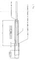
- the wire passing through the lamp seal is preferably at least 1.5 mm in diameter and at most equal to the inner diameter of the quartz or glass envelope forming the seal, as in FIG Figure 1 to 3 shown. Then, when cooling the lamp seal and power supply temperatures of at most 250 ° C are reached, so that the external power and mechanical adapters are protected against overheating.
- the pen cathode is widened to reduce the gas space.
- Cathodes with a length of 30 ⁇ 3 mm and a diameter of 1.5 + 0.2 mm have proven suitable until the material and the diameter (2 mm) are changed.
- the total length in this embodiment is 40 ⁇ 4 mm to the seal and 60 6 mm to the electrical connection outside the lamp.
- a rod-shaped crystal of NdYAG (neodymium-yttrium-aluminum garnet) or a similar crystal pumped by two of the above-mentioned laser excitation lamps is used.
- the lamps and the crystal are arranged in a cavity containing the required optical components and thermal cooling components (water).
- a high performance solid state laser (HPSSL) consists of a cascade of numerous such cavities. Each of these cavities typically provides laser radiation of 500 to 600 watts, converted from a lamp power of 16 to 22 kW (the maximum power of each lamp is 11 kW, typically 8 kW).
- 16 cavities are arranged to form a high-power solid-state laser with an optical output power of 8 kW.
- the in Fig. 4 shown arc approach is a so-called diffuse arc approach 4 at the cathode, which is known from low pressure lamps with an operating pressure of at most 1,000 hPa and a discharge current less than 5 A.
- Lamps according to the invention have a high operating pressure of at least 10,000 hPa and operating currents in a range of typically 5 to 50 A.
- a diffuse arc projection 4 is achieved by a high cathode temperature, which overcomes the strong narrowing effect of high pressures.
- the good electron emission conditions achieved by the high cathode temperature are present over the entire area of the cathode work surface.
- the arc projection 4 forms the majority of the area of the tip / cathode working surface, or more than 50% to 100% of the area of the tip. It appears that the arc projection 4 completely covers the area of the tip / cathode working surface and additionally the following part of the outer cylinder jacket of the cathode.
- the temperature is evenly distributed, with low temperature gradients (about 100 ° C / mm) at the cathode working surface and low material stress, thus providing greater resistance of the material to erosion due to changes in cathode temperature.
- the cause of these temporal temperature changes lies in the regulation of the lamp current, by which a certain laser power is to be achieved for the respective application.
- This regulation is the so-called "Switching mode", where the lamp is at full power for a few seconds (typically 0.5 to 20 seconds) and then switched to low power for a few seconds to put the laser into standby mode. If the application is batch processing, the laser will be used for cutting, welding or drilling for 10 seconds, with a lamp current of 40 A and a lamp power of 10 kW.
- the laser goes into standby mode for another 10 seconds, which equates to a lamp power of 6 A or 1 kW. If the current is changed, the temperature at the cathode also changes accordingly, eg 2,500 ° C at 40 A to 2,000 ° C at 6 A. The life of such cathodes can be more than 1,000 hours, even in switching mode.
- the arc projection 5 is according to FIG Fig. 5 a so-called contracted approach (spot mode), which is typical for high-pressure lamps with a cold cathode, in which the cathode temperatures are well below 1,800 ° C.
- spot mode is typical for high-pressure lamps with a cold cathode, in which the cathode temperatures are well below 1,800 ° C.
- These cathodes are typically provided with an emitter material which reduces the operational function of the cathode so that electron emission can occur at temperatures below 1800 ° C, even to achieve currents of 50A.
- the temperature is maintained at a low level to reduce the erosion caused by the evaporation of the electrode material.
- spot mode on the other hand, the arc projection 5 covers a small area of the cathode whose temperature is e.g.
- the starting process of a gas discharge lamp is a complicated time-dependent process, in which the lamp gas from the cold state (room temperature), in which it is a good insulator, in the hot state (7,000 to 15,000 K in noble gas discharge lamps), in the sufficient electron / ion pairs are transferred to direct the electric current through the gas.
- This process is described using the example of a typical lamp-pumped NdYAG laser (e.g., Trump laser HL 4006 D).
- the ignition of a lamp is a statistical process that can fail for a variety of reasons. In such a failure, the arc can not open the manner described above are made so that the lamp level again takes very high values. This results in a high voltage which corresponds at most to the no-load voltage of the respective power supply, which is typically 500 to 1000 volts.
- the detector uses the lamp voltage prevailing at a certain time (typically 1-10 ms after ignition) as a safe sensor for the lamp condition. Normally, the voltage is about 300 V 3 to 7 ms after ignition. measured after 5 ms. If it does not exceed a value of e.g. 400 V, the system decides that the ignition was successful. If the voltage exceeds a value of e.g. 400 V, it is assumed that a failure of the ignition, and the regulatory system goes into failure state. For this method, knowledge about the temporal behavior of the lamp ignition process and about reproducible ignition conditions over the life of the lamp must be available. The above statements make it clear that this behavior is unique for the lamp type in use.
- Standard type lamps have a pointed cathode which reaches the full diameter of the discharge tube within a few millimeters of the tip.
- the cathode then almost contacts the quartz material, creating a gas gap of about 10 to 20 microns, so that the gas causes cooling and the temperature of the cathode is kept at a low value.
- This design as well as the presence of the emitter material, which enables a cold cathode to emit electrons, results in a contracted arc approach (spot mode) that clearly fails even at the start of the lamp at the top of the cathode.
- these lamps show a reproducible ignition behavior that can be easily used for the ignition method described above.
- Error messages typically take place at one out of 50 or one out of 100 lamp starting operations from the cold state. For a laser with 16 cavities and 32 lamps, it is very likely that an error message will be given every other day when the laser is started. In a workshop with 10 lasers, this happens twice a day in a room.
- this problem can be solved by applying the modified design of the lamp power control unit to lasers already on the market, e.g. by replacing a printed circuit board or by using other software for the microprocessor unit.
- this problem is solved by modifying the pen cathode lamp so that it is compatible with the standard lamp during lamp ignition. This is achieved by a lamp according to claim 1.
- the system achieves greater stability in the ignition phase of the lamp. Stability becomes even greater as the gas volume at the end of the cathode toward the discharge space and around it is reduced to the lowest possible value which still provides the high temperature, diffused arc-loft cathode.
- the pen lamp has gained a fundamentally new characteristic: it is compatible with standard lamps with regard to the lamp ignition. The lamp can now be used in any laser, and any restriction on a specific date of manufacture of the laser system has become obsolete.
Landscapes
- Physics & Mathematics (AREA)
- Electromagnetism (AREA)
- Engineering & Computer Science (AREA)
- Plasma & Fusion (AREA)
- Optics & Photonics (AREA)
- Vessels And Coating Films For Discharge Lamps (AREA)
- Lasers (AREA)
- Discharge Lamps And Accessories Thereof (AREA)
- Discharge Lamp (AREA)
Claims (11)
- Lampe d'excitation laser avec un tube de déchargement en verre de quartz ainsi qu'une cathode incandescente exploitée à chaud (1) sous forme d'une tige, dans laquelle la lampe d'excitation laser présente une réduction du volume d'espace gazeux dans la région de la cathode incandescente (1), dans laquelle la réduction est formée par une réduction de l'écart entre la cathode et le tube de déchargement, caractérisée en ce que la réduction de l'écart entre la cathode et le tube de déchargement est formée par un diamètre externe agrandi de la cathode et la cathode incandescente peut être alimentée à l'extrémité détournée de l'espace de déchargement avec une température supérieure à 1800°C.
- Lampe selon la revendication 1, dans laquelle le volume réduit recouvre entièrement ou partiellement une région entre le joint de traversée de la cathode et 3 mm avant la cathode s'étendant le long de la tige.
- Lampe selon l'une quelconque des revendications précédentes, caractérisée en ce qu'une réduction de volume supplémentaire est obtenue en réduisant le diamètre interne du tube de déchargement dans la région de la cathode à tige.
- Lampe selon l'une quelconque des revendications précédentes, caractérisée en ce qu'une réduction de volume supplémentaire est obtenue en remplissant le volume du tube de déchargement dans la région de la cathode à tige.
- Lampe selon l'une quelconque des revendications précédentes, caractérisée en ce que l'écart entre la surface de la cathode et la surface tournée vers la cathode du matériau qui l'entoure du volume réduit est supérieur à 0,5 mm.
- Lampe selon l'une quelconque des revendications précédentes, caractérisée en ce que le diamètre de la tige est inférieur à 3 mm.
- Lampe selon l'une quelconque des revendications précédentes, dans laquelle le joint de la lampe et l'alimentation électrique sont les seuls thermoconducteurs raccordés à la cathode.
- Lampe selon l'une quelconque des revendications précédentes, dans laquelle le diamètre du fil menant à travers le joint de la lampe est supérieur à 0,9 mm et inférieur au diamètre interne de l'enveloppe de quartz ou de verre formant le joint.
- Lampe selon l'une quelconque des revendications précédentes, dans laquelle le volume réduit est cylindrique.
- Procédé de fabrication d'une lampe à pompage laser selon la revendication 1, caractérisé en ce que des tubes de verre de quartz de diamètre interne différent sont reliés ensemble et un tube de verre de quartz avec un faible diamètre est disposé le long de la cathode.
- Utilisation d'une lampe à pompage laser selon la revendication 1 dans un appareil laser du type HPSSL (laser solide haute performance), caractérisée en ce que la lampe laser possède une cathode à tige et l'espace gazeux autour de la cathode est réduit par rapport à l'espace gazeux du tube de déchargement supplémentaire.
Priority Applications (1)
| Application Number | Priority Date | Filing Date | Title |
|---|---|---|---|
| US11/252,124 US7759849B2 (en) | 2004-10-18 | 2005-10-17 | High-power discharge lamp |
Applications Claiming Priority (1)
| Application Number | Priority Date | Filing Date | Title |
|---|---|---|---|
| GB0423096A GB2419460B (en) | 2004-10-18 | 2004-10-18 | Pumping laser lamp and production method |
Publications (3)
| Publication Number | Publication Date |
|---|---|
| EP1648021A2 EP1648021A2 (fr) | 2006-04-19 |
| EP1648021A3 EP1648021A3 (fr) | 2007-06-06 |
| EP1648021B1 true EP1648021B1 (fr) | 2011-11-02 |
Family
ID=33462910
Family Applications (1)
| Application Number | Title | Priority Date | Filing Date |
|---|---|---|---|
| EP05021136A Active EP1648021B1 (fr) | 2004-10-18 | 2005-09-28 | Lampe à décharge de grande puissance |
Country Status (4)
| Country | Link |
|---|---|
| EP (1) | EP1648021B1 (fr) |
| JP (1) | JP2006114505A (fr) |
| AT (1) | ATE532204T1 (fr) |
| GB (1) | GB2419460B (fr) |
Cited By (1)
| Publication number | Priority date | Publication date | Assignee | Title |
|---|---|---|---|---|
| CN104576294A (zh) * | 2013-10-28 | 2015-04-29 | 优志旺电机株式会社 | 双端型短弧闪光灯 |
Families Citing this family (1)
| Publication number | Priority date | Publication date | Assignee | Title |
|---|---|---|---|---|
| CN104253013B (zh) * | 2014-04-15 | 2018-04-03 | 中国科学技术大学先进技术研究院 | 一种高通量平面光源装置 |
Family Cites Families (11)
| Publication number | Priority date | Publication date | Assignee | Title |
|---|---|---|---|---|
| GB1426047A (en) * | 1972-03-01 | 1976-02-25 | Vickers Ltd | Bottle filling apparatus |
| JPS55124939A (en) * | 1979-03-16 | 1980-09-26 | Nec Home Electronics Ltd | High-pressure electric discharge tube |
| JPS5929340A (ja) * | 1982-08-11 | 1984-02-16 | Oak Kk | 閃光放電管 |
| JPS5929341A (ja) * | 1982-08-11 | 1984-02-16 | Oak Kk | 閃光放電管 |
| GB2199693B (en) * | 1986-12-02 | 1990-08-15 | Noblelight Ltd | Improvements in and relating to flash lamps |
| JP2561902B2 (ja) * | 1988-09-14 | 1996-12-11 | ウシオ電機株式会社 | マイクロ波励起型無電極発光管及びその製造方法 |
| BG50699A1 (en) * | 1990-07-17 | 1992-10-15 | Khandzhieva Florian Bozhana I | Pulse lamp |
| JPH08124521A (ja) * | 1994-10-25 | 1996-05-17 | Fuji Electric Co Ltd | レーザ用励起ランプ |
| JPH1027581A (ja) * | 1996-07-10 | 1998-01-27 | Sakurai Yumiko | 耐圧性外囲器とその製造方法並びに前記外囲器を使用したランプ |
| US5898270A (en) * | 1997-04-11 | 1999-04-27 | Ilc Technology, Inc. | Monocoque structure and large electrode beaded rob re-entrant seals for flashlamp-pumped solid-state laser flashlamps |
| DE10208585B4 (de) * | 2002-02-22 | 2004-03-25 | Trumpf Laser Gmbh + Co. Kg | Pumplichtquelle für laseraktive Medien und Verfahren zu ihrem Betreiben |
-
2004
- 2004-10-18 GB GB0423096A patent/GB2419460B/en active Active
-
2005
- 2005-09-28 EP EP05021136A patent/EP1648021B1/fr active Active
- 2005-09-28 AT AT05021136T patent/ATE532204T1/de active
- 2005-10-17 JP JP2005301255A patent/JP2006114505A/ja active Pending
Cited By (1)
| Publication number | Priority date | Publication date | Assignee | Title |
|---|---|---|---|---|
| CN104576294A (zh) * | 2013-10-28 | 2015-04-29 | 优志旺电机株式会社 | 双端型短弧闪光灯 |
Also Published As
| Publication number | Publication date |
|---|---|
| GB2419460A (en) | 2006-04-26 |
| EP1648021A3 (fr) | 2007-06-06 |
| GB2419460B (en) | 2009-07-29 |
| ATE532204T1 (de) | 2011-11-15 |
| GB0423096D0 (en) | 2004-11-17 |
| JP2006114505A (ja) | 2006-04-27 |
| EP1648021A2 (fr) | 2006-04-19 |
Similar Documents
| Publication | Publication Date | Title |
|---|---|---|
| EP0834905B1 (fr) | Lampe haute pression au sodium de faible puissance | |
| DE60019698T2 (de) | Metallhalogenidlampe | |
| EP1481418B1 (fr) | Lampe a decharge haute pression a arc court | |
| DE2718642C2 (de) | Elektrode für eine Hochdruck-Metallhalogenidlampe | |
| DE10062974A1 (de) | Hochdruckgasentladungslampe und Verfahren zu ihrer Herstellung | |
| DE69731374T2 (de) | Niederdruckentladunglampe | |
| EP0736222A1 (fr) | Lampe halogene a incandescence | |
| DE3021209A1 (de) | Beleuchtungseinheit | |
| EP1648021B1 (fr) | Lampe à décharge de grande puissance | |
| DE2341377A1 (de) | Elektronenstrahlroehre mit thermionikfeld-emissionskathode fuer ein abtastendes elektronenmikroskop | |
| DE3015451C2 (de) | Metalldampfentladungslampe | |
| DE2502649A1 (de) | Verbesserte elektrodenstruktur fuer hochstrom-niederdruck-entladungsvorrichtungen | |
| DE2264005B2 (de) | Gasentladungsröhre | |
| EP1481417A1 (fr) | Lampe au mercure a arc court dotee d'une cathode contenant de l'oxyde de lanthane | |
| DE102006052715B4 (de) | Verfahren zur Herstellung einer quecksilberfreien Bogenentladungsröhre mit jeweils einem Einkristall an den Elektrodenspitzen | |
| DE2625554C2 (de) | Wandstabilisierte Blitzröhre | |
| DE4008375A1 (de) | Hochdruckentladungslampe | |
| DE3904552A1 (de) | Hochdruckentladungslampe fuer den betrieb mit wechselstrom | |
| DE2435177A1 (de) | Bogenlampe | |
| DE102005017371A1 (de) | Hochleistungsentladungslampe | |
| DE838801C (de) | Elektrische Entladungseinrichtung der Niederdrucktype | |
| DE3106201A1 (de) | Hochdruck-gasentladungslampe | |
| DE840416C (de) | Elektrische Entladungslampe fuer hohe Temperaturen | |
| DE2311620C3 (de) | Elektrode für Kurzbogengasentladungslampen und Verfahren zu ihrer Herstellung | |
| DE2941114C2 (de) | Hochdruck-Natriumdampf-Entladungslampe |
Legal Events
| Date | Code | Title | Description |
|---|---|---|---|
| PUAI | Public reference made under article 153(3) epc to a published international application that has entered the european phase |
Free format text: ORIGINAL CODE: 0009012 |
|
| 17P | Request for examination filed |
Effective date: 20051006 |
|
| AK | Designated contracting states |
Kind code of ref document: A2 Designated state(s): AT BE BG CH CY CZ DE DK EE ES FI FR GB GR HU IE IS IT LI LT LU LV MC NL PL PT RO SE SI SK TR |
|
| AX | Request for extension of the european patent |
Extension state: AL BA HR MK YU |
|
| PUAL | Search report despatched |
Free format text: ORIGINAL CODE: 0009013 |
|
| AK | Designated contracting states |
Kind code of ref document: A3 Designated state(s): AT BE BG CH CY CZ DE DK EE ES FI FR GB GR HU IE IS IT LI LT LU LV MC NL PL PT RO SE SI SK TR |
|
| AX | Request for extension of the european patent |
Extension state: AL BA HR MK YU |
|
| AKX | Designation fees paid |
Designated state(s): AT BE BG CH CY CZ DE DK EE ES FI FR GB GR HU IE IS IT LI LT LU LV MC NL PL PT RO SE SI SK TR |
|
| 17Q | First examination report despatched |
Effective date: 20080610 |
|
| GRAP | Despatch of communication of intention to grant a patent |
Free format text: ORIGINAL CODE: EPIDOSNIGR1 |
|
| GRAS | Grant fee paid |
Free format text: ORIGINAL CODE: EPIDOSNIGR3 |
|
| GRAA | (expected) grant |
Free format text: ORIGINAL CODE: 0009210 |
|
| AK | Designated contracting states |
Kind code of ref document: B1 Designated state(s): AT BE BG CH CY CZ DE DK EE ES FI FR GB GR HU IE IS IT LI LT LU LV MC NL PL PT RO SE SI SK TR |
|
| REG | Reference to a national code |
Ref country code: GB Ref legal event code: FG4D Free format text: NOT ENGLISH |
|
| REG | Reference to a national code |
Ref country code: CH Ref legal event code: EP |
|
| REG | Reference to a national code |
Ref country code: IE Ref legal event code: FG4D |
|
| REG | Reference to a national code |
Ref country code: DE Ref legal event code: R096 Ref document number: 502005012087 Country of ref document: DE Effective date: 20120105 |
|
| REG | Reference to a national code |
Ref country code: NL Ref legal event code: VDEP Effective date: 20111102 |
|
| LTIE | Lt: invalidation of european patent or patent extension |
Effective date: 20111102 |
|
| PG25 | Lapsed in a contracting state [announced via postgrant information from national office to epo] |
Ref country code: LT Free format text: LAPSE BECAUSE OF FAILURE TO SUBMIT A TRANSLATION OF THE DESCRIPTION OR TO PAY THE FEE WITHIN THE PRESCRIBED TIME-LIMIT Effective date: 20111102 Ref country code: IS Free format text: LAPSE BECAUSE OF FAILURE TO SUBMIT A TRANSLATION OF THE DESCRIPTION OR TO PAY THE FEE WITHIN THE PRESCRIBED TIME-LIMIT Effective date: 20120302 |
|
| PG25 | Lapsed in a contracting state [announced via postgrant information from national office to epo] |
Ref country code: PL Free format text: LAPSE BECAUSE OF FAILURE TO SUBMIT A TRANSLATION OF THE DESCRIPTION OR TO PAY THE FEE WITHIN THE PRESCRIBED TIME-LIMIT Effective date: 20111102 Ref country code: PT Free format text: LAPSE BECAUSE OF FAILURE TO SUBMIT A TRANSLATION OF THE DESCRIPTION OR TO PAY THE FEE WITHIN THE PRESCRIBED TIME-LIMIT Effective date: 20120302 Ref country code: GR Free format text: LAPSE BECAUSE OF FAILURE TO SUBMIT A TRANSLATION OF THE DESCRIPTION OR TO PAY THE FEE WITHIN THE PRESCRIBED TIME-LIMIT Effective date: 20120203 Ref country code: NL Free format text: LAPSE BECAUSE OF FAILURE TO SUBMIT A TRANSLATION OF THE DESCRIPTION OR TO PAY THE FEE WITHIN THE PRESCRIBED TIME-LIMIT Effective date: 20111102 Ref country code: SE Free format text: LAPSE BECAUSE OF FAILURE TO SUBMIT A TRANSLATION OF THE DESCRIPTION OR TO PAY THE FEE WITHIN THE PRESCRIBED TIME-LIMIT Effective date: 20111102 Ref country code: LV Free format text: LAPSE BECAUSE OF FAILURE TO SUBMIT A TRANSLATION OF THE DESCRIPTION OR TO PAY THE FEE WITHIN THE PRESCRIBED TIME-LIMIT Effective date: 20111102 Ref country code: SI Free format text: LAPSE BECAUSE OF FAILURE TO SUBMIT A TRANSLATION OF THE DESCRIPTION OR TO PAY THE FEE WITHIN THE PRESCRIBED TIME-LIMIT Effective date: 20111102 |
|
| REG | Reference to a national code |
Ref country code: IE Ref legal event code: FD4D |
|
| PG25 | Lapsed in a contracting state [announced via postgrant information from national office to epo] |
Ref country code: CY Free format text: LAPSE BECAUSE OF FAILURE TO SUBMIT A TRANSLATION OF THE DESCRIPTION OR TO PAY THE FEE WITHIN THE PRESCRIBED TIME-LIMIT Effective date: 20111102 |
|
| PG25 | Lapsed in a contracting state [announced via postgrant information from national office to epo] |
Ref country code: IE Free format text: LAPSE BECAUSE OF FAILURE TO SUBMIT A TRANSLATION OF THE DESCRIPTION OR TO PAY THE FEE WITHIN THE PRESCRIBED TIME-LIMIT Effective date: 20111102 Ref country code: CZ Free format text: LAPSE BECAUSE OF FAILURE TO SUBMIT A TRANSLATION OF THE DESCRIPTION OR TO PAY THE FEE WITHIN THE PRESCRIBED TIME-LIMIT Effective date: 20111102 Ref country code: SK Free format text: LAPSE BECAUSE OF FAILURE TO SUBMIT A TRANSLATION OF THE DESCRIPTION OR TO PAY THE FEE WITHIN THE PRESCRIBED TIME-LIMIT Effective date: 20111102 Ref country code: EE Free format text: LAPSE BECAUSE OF FAILURE TO SUBMIT A TRANSLATION OF THE DESCRIPTION OR TO PAY THE FEE WITHIN THE PRESCRIBED TIME-LIMIT Effective date: 20111102 Ref country code: DK Free format text: LAPSE BECAUSE OF FAILURE TO SUBMIT A TRANSLATION OF THE DESCRIPTION OR TO PAY THE FEE WITHIN THE PRESCRIBED TIME-LIMIT Effective date: 20111102 Ref country code: BG Free format text: LAPSE BECAUSE OF FAILURE TO SUBMIT A TRANSLATION OF THE DESCRIPTION OR TO PAY THE FEE WITHIN THE PRESCRIBED TIME-LIMIT Effective date: 20120202 |
|
| PG25 | Lapsed in a contracting state [announced via postgrant information from national office to epo] |
Ref country code: RO Free format text: LAPSE BECAUSE OF FAILURE TO SUBMIT A TRANSLATION OF THE DESCRIPTION OR TO PAY THE FEE WITHIN THE PRESCRIBED TIME-LIMIT Effective date: 20111102 |
|
| PLBE | No opposition filed within time limit |
Free format text: ORIGINAL CODE: 0009261 |
|
| STAA | Information on the status of an ep patent application or granted ep patent |
Free format text: STATUS: NO OPPOSITION FILED WITHIN TIME LIMIT |
|
| 26N | No opposition filed |
Effective date: 20120803 |
|
| REG | Reference to a national code |
Ref country code: DE Ref legal event code: R097 Ref document number: 502005012087 Country of ref document: DE Effective date: 20120803 |
|
| BERE | Be: lapsed |
Owner name: HERAEUS NOBLELIGHT LTD. Effective date: 20120930 |
|
| PG25 | Lapsed in a contracting state [announced via postgrant information from national office to epo] |
Ref country code: ES Free format text: LAPSE BECAUSE OF FAILURE TO SUBMIT A TRANSLATION OF THE DESCRIPTION OR TO PAY THE FEE WITHIN THE PRESCRIBED TIME-LIMIT Effective date: 20120213 Ref country code: MC Free format text: LAPSE BECAUSE OF NON-PAYMENT OF DUE FEES Effective date: 20120930 |
|
| REG | Reference to a national code |
Ref country code: CH Ref legal event code: PL |
|
| PG25 | Lapsed in a contracting state [announced via postgrant information from national office to epo] |
Ref country code: FI Free format text: LAPSE BECAUSE OF FAILURE TO SUBMIT A TRANSLATION OF THE DESCRIPTION OR TO PAY THE FEE WITHIN THE PRESCRIBED TIME-LIMIT Effective date: 20111102 |
|
| PG25 | Lapsed in a contracting state [announced via postgrant information from national office to epo] |
Ref country code: LI Free format text: LAPSE BECAUSE OF NON-PAYMENT OF DUE FEES Effective date: 20120930 Ref country code: CH Free format text: LAPSE BECAUSE OF NON-PAYMENT OF DUE FEES Effective date: 20120930 Ref country code: BE Free format text: LAPSE BECAUSE OF NON-PAYMENT OF DUE FEES Effective date: 20120930 |
|
| REG | Reference to a national code |
Ref country code: AT Ref legal event code: MM01 Ref document number: 532204 Country of ref document: AT Kind code of ref document: T Effective date: 20120928 |
|
| PG25 | Lapsed in a contracting state [announced via postgrant information from national office to epo] |
Ref country code: AT Free format text: LAPSE BECAUSE OF NON-PAYMENT OF DUE FEES Effective date: 20120928 |
|
| PG25 | Lapsed in a contracting state [announced via postgrant information from national office to epo] |
Ref country code: TR Free format text: LAPSE BECAUSE OF FAILURE TO SUBMIT A TRANSLATION OF THE DESCRIPTION OR TO PAY THE FEE WITHIN THE PRESCRIBED TIME-LIMIT Effective date: 20111102 |
|
| PG25 | Lapsed in a contracting state [announced via postgrant information from national office to epo] |
Ref country code: LU Free format text: LAPSE BECAUSE OF NON-PAYMENT OF DUE FEES Effective date: 20120928 |
|
| PG25 | Lapsed in a contracting state [announced via postgrant information from national office to epo] |
Ref country code: HU Free format text: LAPSE BECAUSE OF FAILURE TO SUBMIT A TRANSLATION OF THE DESCRIPTION OR TO PAY THE FEE WITHIN THE PRESCRIBED TIME-LIMIT Effective date: 20050928 |
|
| REG | Reference to a national code |
Ref country code: FR Ref legal event code: PLFP Year of fee payment: 12 |
|
| REG | Reference to a national code |
Ref country code: FR Ref legal event code: PLFP Year of fee payment: 13 |
|
| REG | Reference to a national code |
Ref country code: DE Ref legal event code: R082 Ref document number: 502005012087 Country of ref document: DE Representative=s name: BRAND, NORMEN, DR. RER. NAT., DE Ref country code: DE Ref legal event code: R082 Ref document number: 502005012087 Country of ref document: DE Representative=s name: BRAND, NORMEN, DIPL.-CHEM. UNIV. DR. RER. NAT., DE Ref country code: DE Ref legal event code: R082 Ref document number: 502005012087 Country of ref document: DE Representative=s name: EULER, MATTHIAS, DR., DE |
|
| REG | Reference to a national code |
Ref country code: FR Ref legal event code: PLFP Year of fee payment: 14 |
|
| PGFP | Annual fee paid to national office [announced via postgrant information from national office to epo] |
Ref country code: IT Payment date: 20190925 Year of fee payment: 15 Ref country code: FR Payment date: 20190926 Year of fee payment: 15 |
|
| REG | Reference to a national code |
Ref country code: DE Ref legal event code: R082 Ref document number: 502005012087 Country of ref document: DE Representative=s name: BRAND, NORMEN, DR. RER. NAT., DE Ref country code: DE Ref legal event code: R082 Ref document number: 502005012087 Country of ref document: DE Representative=s name: BRAND, NORMEN, DIPL.-CHEM. UNIV. DR. RER. NAT., DE |
|
| PG25 | Lapsed in a contracting state [announced via postgrant information from national office to epo] |
Ref country code: FR Free format text: LAPSE BECAUSE OF NON-PAYMENT OF DUE FEES Effective date: 20200930 |
|
| PG25 | Lapsed in a contracting state [announced via postgrant information from national office to epo] |
Ref country code: IT Free format text: LAPSE BECAUSE OF NON-PAYMENT OF DUE FEES Effective date: 20200928 |
|
| P01 | Opt-out of the competence of the unified patent court (upc) registered |
Effective date: 20230530 |
|
| PGFP | Annual fee paid to national office [announced via postgrant information from national office to epo] |
Ref country code: GB Payment date: 20230920 Year of fee payment: 19 |
|
| PGFP | Annual fee paid to national office [announced via postgrant information from national office to epo] |
Ref country code: DE Payment date: 20230920 Year of fee payment: 19 |
|
| REG | Reference to a national code |
Ref country code: DE Ref legal event code: R082 Ref document number: 502005012087 Country of ref document: DE Representative=s name: MEWBURN ELLIS LLP, DE |