EP1647838B1 - Verfahren und Messgerät zur Messung eines Absolutdistanzwertes - Google Patents
Verfahren und Messgerät zur Messung eines Absolutdistanzwertes Download PDFInfo
- Publication number
- EP1647838B1 EP1647838B1 EP04405638A EP04405638A EP1647838B1 EP 1647838 B1 EP1647838 B1 EP 1647838B1 EP 04405638 A EP04405638 A EP 04405638A EP 04405638 A EP04405638 A EP 04405638A EP 1647838 B1 EP1647838 B1 EP 1647838B1
- Authority
- EP
- European Patent Office
- Prior art keywords
- distance
- absolute distance
- absolute
- measuring
- measuring device
- Prior art date
- Legal status (The legal status is an assumption and is not a legal conclusion. Google has not performed a legal analysis and makes no representation as to the accuracy of the status listed.)
- Expired - Lifetime
Links
- 238000000034 method Methods 0.000 title claims abstract description 34
- 238000005259 measurement Methods 0.000 title abstract description 47
- 238000005070 sampling Methods 0.000 claims description 23
- 238000006073 displacement reaction Methods 0.000 claims description 5
- 238000012935 Averaging Methods 0.000 claims description 4
- 238000001914 filtration Methods 0.000 claims description 4
- 230000010354 integration Effects 0.000 claims description 4
- 238000011156 evaluation Methods 0.000 claims description 3
- 230000001419 dependent effect Effects 0.000 claims 2
- 230000001052 transient effect Effects 0.000 claims 2
- 238000012937 correction Methods 0.000 description 6
- 238000013459 approach Methods 0.000 description 2
- 230000001427 coherent effect Effects 0.000 description 2
- 230000008030 elimination Effects 0.000 description 2
- 238000003379 elimination reaction Methods 0.000 description 2
- 238000005305 interferometry Methods 0.000 description 2
- 238000000691 measurement method Methods 0.000 description 2
- 238000001514 detection method Methods 0.000 description 1
- 239000011888 foil Substances 0.000 description 1
- 238000012804 iterative process Methods 0.000 description 1
- 230000003287 optical effect Effects 0.000 description 1
- 230000010287 polarization Effects 0.000 description 1
- 238000012545 processing Methods 0.000 description 1
- 230000003252 repetitive effect Effects 0.000 description 1
- 230000001360 synchronised effect Effects 0.000 description 1
Images
Classifications
-
- G—PHYSICS
- G01—MEASURING; TESTING
- G01S—RADIO DIRECTION-FINDING; RADIO NAVIGATION; DETERMINING DISTANCE OR VELOCITY BY USE OF RADIO WAVES; LOCATING OR PRESENCE-DETECTING BY USE OF THE REFLECTION OR RERADIATION OF RADIO WAVES; ANALOGOUS ARRANGEMENTS USING OTHER WAVES
- G01S7/00—Details of systems according to groups G01S13/00, G01S15/00, G01S17/00
- G01S7/48—Details of systems according to groups G01S13/00, G01S15/00, G01S17/00 of systems according to group G01S17/00
- G01S7/481—Constructional features, e.g. arrangements of optical elements
-
- G—PHYSICS
- G01—MEASURING; TESTING
- G01S—RADIO DIRECTION-FINDING; RADIO NAVIGATION; DETERMINING DISTANCE OR VELOCITY BY USE OF RADIO WAVES; LOCATING OR PRESENCE-DETECTING BY USE OF THE REFLECTION OR RERADIATION OF RADIO WAVES; ANALOGOUS ARRANGEMENTS USING OTHER WAVES
- G01S17/00—Systems using the reflection or reradiation of electromagnetic waves other than radio waves, e.g. lidar systems
- G01S17/02—Systems using the reflection of electromagnetic waves other than radio waves
- G01S17/06—Systems determining position data of a target
- G01S17/08—Systems determining position data of a target for measuring distance only
- G01S17/32—Systems determining position data of a target for measuring distance only using transmission of continuous waves, whether amplitude-, frequency-, or phase-modulated, or unmodulated
- G01S17/36—Systems determining position data of a target for measuring distance only using transmission of continuous waves, whether amplitude-, frequency-, or phase-modulated, or unmodulated with phase comparison between the received signal and the contemporaneously transmitted signal
-
- G—PHYSICS
- G01—MEASURING; TESTING
- G01S—RADIO DIRECTION-FINDING; RADIO NAVIGATION; DETERMINING DISTANCE OR VELOCITY BY USE OF RADIO WAVES; LOCATING OR PRESENCE-DETECTING BY USE OF THE REFLECTION OR RERADIATION OF RADIO WAVES; ANALOGOUS ARRANGEMENTS USING OTHER WAVES
- G01S7/00—Details of systems according to groups G01S13/00, G01S15/00, G01S17/00
- G01S7/48—Details of systems according to groups G01S13/00, G01S15/00, G01S17/00 of systems according to group G01S17/00
- G01S7/499—Details of systems according to groups G01S13/00, G01S15/00, G01S17/00 of systems according to group G01S17/00 using polarisation effects
Definitions
- the invention relates to the field of electro-optical distance measurement. It relates to a method and a measuring device for measuring an absolute distance value according to the preamble of the corresponding independent patent claims.
- instruments for the determination of relative distances for example laser interferometers
- a collimated laser beam passes from a measuring device to a reflective target.
- the transmitted beam is superimposed on the reflected beam received in the meter.
- the intensity of the superimposed beams changes according to the interference of the two beams.
- Such intensity changes are detected and counted by means of a counter. According to a number of intensity changes and the wavelength of the laser light, the distance change results.
- a known reference value ie an absolute distance in a starting position
- an absolute distance from other positions can thus also be determined.
- target measuring devices are designed as trackers, ie that the laser beam by means of a rotatable mirror automatically the goal is tracked.
- the elevation and azimuth of the laser beam are measured so that the determination of the position of the target in three dimensions is possible. Due to the simple measuring principle, the position can be tracked even at speeds of the target of, for example, up to 10 m / s.
- Such a method for determining a relative distance requires that the beam between the measuring device and the target is not interrupted. If this happens, distance changes are no longer detected and the absolute distance between the measuring device and the target is no longer known. This absolute distance must therefore be redetermined or calibrated by other means.
- Such a combination of an absolute distance meter with an interferometer is in the DE 195 42 490 C1 disclosed.
- WO 02/084327 A2 describes an absolute distance measurement by means of laser light, with a measuring light path and a reference light path, via which the light is passed alternately.
- the measurement light path leads over the measurement path and is used for an absolute distance measurement procedure.
- the reference light path is inside the meter. Thus, a distance change of an internal reference light path is determined to compensate for drift and temperature-induced changes.
- WO 00/63645 is an indirect position determination using a tracker described.
- a position of a reference point of a measuring instrument is to be determined, wherein the reference point itself is not visible from the tracker.
- a retroreflector is moved along the measuring instrument along a known path, with the tracker following it. From the measured positions of the retroreflector and from the known geometry of the measuring instrument, the position and orientation of the reference point can be determined.
- a distance measuring device having both means for determining an absolute distance and means for determining a relative distance between the measuring device and a target, changes in distance which occur during an absolute distance determination are combined with the means for determining the relative Detected distance and taken into account in determining the absolute distance.
- the means for determining the absolute distance for performing an iterative method is formed. This means that the method gradually approaches the correct absolute distance value over several sampling steps. In each sampling step, an output value is determined from an input value, which depends on the input value and on the distance. A distance change that occurs between a first sampling step and a subsequent second sampling step due to a Movement of the target and / or the meter is detected with the means for determining the relative distance and used in the determination of the input value for the second sampling step to compensate for the distance change.
- the iterative process can converge without being thrown off track by distance changes.
- the method for measuring the absolute distance value is a Fizeau method.
- the input value is a modulation frequency which acts on an outgoing and a returning light beam
- the output value is an intensity of the returning light beam after its modulation.
- the means for determining the absolute distance for determining a plurality of measured values for the absolute distance is formed.
- these measured values are filtered, for example by integration or averaging.
- this distance change is simultaneously detected by the means for determining the relative distance, and the synchronous values of the distance change before the filtering are subtracted from the measured values.
- the FIG. 1 schematically shows a structure of a distance measuring device according to the invention, with a combined absolute value measurement according to a preferred embodiment of the invention.
- Outgoing light beams from an absolute distance meter 1 and from a relative distance meter 2 are combined by a first beam splitter 4, respectively returning light is split between these two distance meters 1, 2.
- the first beam splitter 4 for example, a dichroic beam splitter.
- a control unit 3 is arranged to exchange data and control signals with both the absolute distance meter 1 and the relative distance meter 2.
- the control unit 3 transmits data from the relative distance meter 2 to the absolute distance meter 1, and / or combines data or measured distance values originating from these two distance meters 1, 2 together.
- the light beams pass through a second beam splitter 5 to a tracking mirror 7 rotatable about two axes.
- a tracking controller 6 detects a part of the returning light with a position-sensitive diode (PSD) and regulates the position of the tracking in accordance with its displacement Mirror 7 so that the light beam follows a reflective target or reflector 8.
- the reflector 8 has, for example, a roof edge prism or a reflector film.
- the measuring section 9 runs along the radiated respectively the reflected light beams between a predetermined reference zero point in the measuring device 10 and the reflector 8.
- the measuring device 10 also has further electrical and optical means, as are known from the cited prior art, for example for deflecting and collimating the light beams. For the sake of simplicity, however, these are not shown.
- the measuring device 10 or parts thereof are installed in a preferred embodiment of the invention in the support of a motorized theodolite or in a measuring column. When installed in a theodolite support, the tracking mirror 7 is omitted.
- the relative distance meter 2 is preferably an interferometer.
- the latter has an up-down counter which registers instantaneous values of the displacement of the reflector. With each movement of the target in the measuring direction by half a wavelength of light, a counter pulse is added or subtracted depending on the direction of displacement in the counter. In the case of a HeNe laser, for example, this takes place every 0.32 micrometers. The meter reading can be read out and stored at any time.
- the absolute distance meter 1 is preferably a distance meter according to the Fizeau principle.
- the measuring light beam is at the fizzle by the same modulator modulated twice, once as a transmit beam on entering the measurement path, and a second time as a returning beam or receive beam on exit from the measurement path.
- the modulation for example, a polarization and / or the intensity and / or the frequency of the light is modulated.
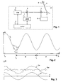
- the light intensity after the second modulation or back modulation in function of the reflector distance and the modulation frequency changed periodically arise, for example, when linearly changing the modulation frequency and fixed distance alternately places lower and high light intensity A points at the output of the demodulation, such as in the FIG. 2 shown.
- This light intensity A is measured with a photodiode.
- the light modulation frequency f is preferably additionally frequency-modulated: For example, a sinusoidal frequency modulation (FM) of 20 kHz with a stroke of approximately 500 kHz is performed at a fundamental frequency f in a band between 2 and 2.3 GHz.
- FM sinusoidal frequency modulation
- a zero crossing of the FM-modulated signal takes place. Such a zero crossing is easier to detect than a minimum.
- the determination of the amplitude of the received signal at a given fundamental frequency - with or without the additional FM modulation - is hereinafter referred to as sampling for the sake of simplicity.
- At least two minima ie two adjacent zero crossings of the demodulated signal.
- the corresponding frequencies are f0 and f1. These zeros are determined iteratively by varying the fundamental frequency.
- an adapted frequency step size is used at each step, which leads as quickly as possible to the sought zero crossing, and wherein the last steps are determined by the maximum desired resolution, eg 1 ppm. is calculated. This results in a time-optimized sampling sequence of frequency steps, which leads to the zero-crossing frequency or minumum frequency f0, f1,.
- the measuring time for a first distance determination for example, lasts 200 milliseconds, from which it is then possible to determine approximately ten values per second by repetitive measurement at a zero point.
- Various devices and methods for such a distance measurement are mentioned in the opening paragraph DE 195 42 490 C1 described.
- either the absolute distance meter is integrated in the beam path of the interferometer, so that both methods of measurement work with light from the same source.
- the two measuring systems work, as in the FIG. 1 shown, with different wavelengths of light.
- the interferometer uses a HeNe laser and the absolute distance meter uses a 780 nm laser diode.
- a coarse measurement of the distance can be made by scanning a plurality of input values within a predetermined bandwidth, as will be described below. After a first determination of the minimum, it is preferably repeated a few times in order to determine from the results an average value as the zero-crossing frequency f0, f1. In total, for example, 20 samples are needed for the coarse measurement, about 20 samples for the iteration and 10 samples for the repeated determination of the minimum, giving a duration of 50 ms at 1 ms per sample.
- a determination of the relative distance change is performed simultaneously with the individual samples, in particular during the iteration, for example by means of an interferometric method.
- a new iteration step is corrected according to the thus measured relative movement of the target between the last and the new scan.
- a coarse measurement of the distance will be made at the beginning of the measurement to determine the absolute distance.
- the zero spacing f 0 - f 1 and from this the coarse distance D 0 c 0 2 ⁇ f 0 - f 1 ⁇ n G certainly.
- the step correction is standardized in each case with this value.
- the coarse measurement can be done by a "scan" over the Modulation bandwidth of the modulator, ie by the determination of a plurality of samples within the modulation bandwidth.
- the distance shift of the reflector during this scan should not exceed approx.
- the compensation of the relative movements is likewise carried out.
- the determination of the minimum is performed for at least two different frequencies f0 and f1. Since, after the presence of these values, the subsequent calculation of the corresponding distance D requires a certain computing time, the relative position is also tracked during this computing time. After the distance is known, it is corrected by the current distance change accumulated in the meantime and then used as the reference value for the relative distance meter 2. For example, to set the counter in the relative distance meter 2 corresponding to the reference value, or a constant offset corresponding to the reference value is added to the distance.
- this value is determined for the relative distance determination, e.g. handed over to the interferometer. Thereafter, the distance value via the interferometer measured value also follows fast movements, for example with more than 5 m / s.
- the absolute distance meter uses two wavelengths of light, for example, in addition to the mentioned 780 nm laser diode still a laser diode having a wavelength of, for example, below 450 nm ("blue") is used, and their light in coupled the measuring beam.
- two distance measurements with different wavelengths are carried out, which enables a compensation or elimination of the refractive index of the air.
- a transit time measurement is performed to determine the absolute distance.
- these values are corrected in accordance with the relative movement.
- FIG. 3 shows by way of example a sequence of measured values Da of an absolute distance detection, a sequence of a simultaneously detected relative position dr, and a corrected sequence of absolute distances Dac resulting from the difference Da-dr.
- relative position values are used as correction values dr, which correspond at least approximately to a position of the target at the moment of reflection of the measurement light.
- the method is analogous to the elimination of noise in a sequence of absolute values by averaging or integration applicable.
Landscapes
- Physics & Mathematics (AREA)
- Engineering & Computer Science (AREA)
- Electromagnetism (AREA)
- General Physics & Mathematics (AREA)
- Radar, Positioning & Navigation (AREA)
- Remote Sensing (AREA)
- Computer Networks & Wireless Communication (AREA)
- Length Measuring Devices By Optical Means (AREA)
- Optical Radar Systems And Details Thereof (AREA)
- Instruments For Measurement Of Length By Optical Means (AREA)
- Measurement Of Optical Distance (AREA)
- Radar Systems Or Details Thereof (AREA)
- Length Measuring Devices With Unspecified Measuring Means (AREA)
Priority Applications (9)
| Application Number | Priority Date | Filing Date | Title |
|---|---|---|---|
| EP04405638A EP1647838B1 (de) | 2004-10-13 | 2004-10-13 | Verfahren und Messgerät zur Messung eines Absolutdistanzwertes |
| DE502004011107T DE502004011107D1 (de) | 2004-10-13 | 2004-10-13 | Verfahren und Messgerät zur Messung eines Absolutdistanzwertes |
| AT04405638T ATE466298T1 (de) | 2004-10-13 | 2004-10-13 | Verfahren und messgerät zur messung eines absolutdistanzwertes |
| CA2584347A CA2584347C (en) | 2004-10-13 | 2005-09-29 | Method and measuring device for measuring an absolute distance |
| CNB2005800425689A CN100549726C (zh) | 2004-10-13 | 2005-09-29 | 用于测量绝对距离的方法和测量装置 |
| PCT/CH2005/000560 WO2006039820A1 (de) | 2004-10-13 | 2005-09-29 | Verfahren und messgerät zur messung eines absolutdistanzwertes |
| AU2005294044A AU2005294044B2 (en) | 2004-10-13 | 2005-09-29 | Method and measuring device for measuring an absolute distance |
| US11/577,159 US7609387B2 (en) | 2004-10-13 | 2005-09-29 | Method and measuring device for measuring an absolute distance |
| JP2007535974A JP4995089B2 (ja) | 2004-10-13 | 2005-09-29 | 絶対距離値を測定する方法及び測定装置 |
Applications Claiming Priority (1)
| Application Number | Priority Date | Filing Date | Title |
|---|---|---|---|
| EP04405638A EP1647838B1 (de) | 2004-10-13 | 2004-10-13 | Verfahren und Messgerät zur Messung eines Absolutdistanzwertes |
Publications (2)
| Publication Number | Publication Date |
|---|---|
| EP1647838A1 EP1647838A1 (de) | 2006-04-19 |
| EP1647838B1 true EP1647838B1 (de) | 2010-04-28 |
Family
ID=34932315
Family Applications (1)
| Application Number | Title | Priority Date | Filing Date |
|---|---|---|---|
| EP04405638A Expired - Lifetime EP1647838B1 (de) | 2004-10-13 | 2004-10-13 | Verfahren und Messgerät zur Messung eines Absolutdistanzwertes |
Country Status (9)
| Country | Link |
|---|---|
| US (1) | US7609387B2 (enExample) |
| EP (1) | EP1647838B1 (enExample) |
| JP (1) | JP4995089B2 (enExample) |
| CN (1) | CN100549726C (enExample) |
| AT (1) | ATE466298T1 (enExample) |
| AU (1) | AU2005294044B2 (enExample) |
| CA (1) | CA2584347C (enExample) |
| DE (1) | DE502004011107D1 (enExample) |
| WO (1) | WO2006039820A1 (enExample) |
Families Citing this family (11)
| Publication number | Priority date | Publication date | Assignee | Title |
|---|---|---|---|---|
| JP2007309677A (ja) * | 2006-05-16 | 2007-11-29 | Mitsutoyo Corp | 追尾式レーザ干渉計の絶対距離推定方法及び追尾式レーザ干渉計 |
| US8767215B2 (en) * | 2007-06-18 | 2014-07-01 | Leddartech Inc. | Method for detecting objects with light |
| CN101952741B (zh) * | 2008-02-19 | 2013-06-19 | 莱卡地球系统公开股份有限公司 | 光电距离测量仪 |
| CN102803990B (zh) | 2009-06-23 | 2014-08-06 | 莱卡地球系统公开股份有限公司 | 跟踪方法和具有激光跟踪器的测量系统 |
| EP2653908A1 (en) | 2012-04-16 | 2013-10-23 | Leica Geosystems AG | Electro-optic modulator and electro-optic distance-measuring device |
| EP2653884A1 (en) * | 2012-04-16 | 2013-10-23 | Leica Geosystems AG | Electro-optic distance-measuring device |
| EP2662702A1 (de) * | 2012-05-07 | 2013-11-13 | Leica Geosystems AG | Lasertracker mit Interferometer und Absolutdistanzmesseinheit sowie Kalibrierverfahren für einen Lasertracker |
| CN103499338A (zh) * | 2013-05-14 | 2014-01-08 | 罗江临 | 一种保证激光测距仪量程和提高测量精度的方法 |
| KR102144541B1 (ko) * | 2014-05-08 | 2020-08-18 | 주식회사 히타치엘지 데이터 스토리지 코리아 | 2방향 거리 검출 장치 |
| JPWO2017038659A1 (ja) * | 2015-09-01 | 2018-06-14 | 国立大学法人 東京大学 | 運動検出装置及びそれを用いた三次元形状測定装置 |
| TWI595252B (zh) * | 2016-05-10 | 2017-08-11 | 財團法人工業技術研究院 | 測距裝置及其測距方法 |
Family Cites Families (11)
| Publication number | Priority date | Publication date | Assignee | Title |
|---|---|---|---|---|
| US4606638A (en) * | 1983-11-03 | 1986-08-19 | Zygo Corporation | Distance measuring interferometer and method of use |
| US4714339B2 (en) * | 1986-02-28 | 2000-05-23 | Us Commerce | Three and five axis laser tracking systems |
| JPH0430484Y2 (enExample) * | 1986-09-11 | 1992-07-23 | ||
| CH674675A5 (enExample) * | 1987-10-23 | 1990-06-29 | Kern & Co Ag | |
| DE4314488C2 (de) * | 1993-05-03 | 1997-11-20 | Heidenhain Gmbh Dr Johannes | Interferometrisches Meßverfahren für Absolutmessungen sowie dafür geeignete Laserinterferometeranordnung |
| DE19542490C1 (de) * | 1995-11-15 | 1997-06-05 | Leica Ag | Elektro-optisches Meßgerät für absolute Distanzen |
| JPH09264960A (ja) | 1996-03-28 | 1997-10-07 | Koden Electron Co Ltd | 光学式速度計及び距離計 |
| EP1171752B1 (de) * | 1999-04-19 | 2005-07-06 | Leica Geosystems AG | Indirekte positionsbestimmung mit hilfe eines trackers |
| DE60238612D1 (de) * | 2001-04-10 | 2011-01-27 | Faro Tech Inc | Chopper-stabilisiertes messgerät für absolute distanzen |
| EP1172637B1 (en) | 2001-04-12 | 2003-01-15 | Agilent Technologies, Inc. (a Delaware corporation) | Device for calibrating a wavelength measuring unit |
| US7285793B2 (en) * | 2005-07-15 | 2007-10-23 | Verisurf Software, Inc. | Coordinate tracking system, apparatus and method of use |
-
2004
- 2004-10-13 DE DE502004011107T patent/DE502004011107D1/de not_active Expired - Lifetime
- 2004-10-13 EP EP04405638A patent/EP1647838B1/de not_active Expired - Lifetime
- 2004-10-13 AT AT04405638T patent/ATE466298T1/de not_active IP Right Cessation
-
2005
- 2005-09-29 CA CA2584347A patent/CA2584347C/en not_active Expired - Fee Related
- 2005-09-29 US US11/577,159 patent/US7609387B2/en active Active
- 2005-09-29 AU AU2005294044A patent/AU2005294044B2/en not_active Ceased
- 2005-09-29 JP JP2007535974A patent/JP4995089B2/ja not_active Expired - Fee Related
- 2005-09-29 WO PCT/CH2005/000560 patent/WO2006039820A1/de not_active Ceased
- 2005-09-29 CN CNB2005800425689A patent/CN100549726C/zh not_active Expired - Lifetime
Also Published As
| Publication number | Publication date |
|---|---|
| AU2005294044B2 (en) | 2010-05-27 |
| US20090033945A1 (en) | 2009-02-05 |
| JP4995089B2 (ja) | 2012-08-08 |
| US7609387B2 (en) | 2009-10-27 |
| DE502004011107D1 (de) | 2010-06-10 |
| CA2584347A1 (en) | 2006-04-20 |
| WO2006039820A1 (de) | 2006-04-20 |
| CA2584347C (en) | 2013-06-11 |
| ATE466298T1 (de) | 2010-05-15 |
| JP2008516246A (ja) | 2008-05-15 |
| AU2005294044A1 (en) | 2006-04-20 |
| CN100549726C (zh) | 2009-10-14 |
| CN101076743A (zh) | 2007-11-21 |
| EP1647838A1 (de) | 2006-04-19 |
Similar Documents
| Publication | Publication Date | Title |
|---|---|---|
| EP2841961B1 (de) | Verfahren und vorrichtung zur bestimmung von abstand und radialgeschwindigkeit eines objekts mittels radarsignalen | |
| DE19542490C1 (de) | Elektro-optisches Meßgerät für absolute Distanzen | |
| DE60100064T2 (de) | Bestimmung der Eigenschaften eines optischen Gerätes | |
| DE112019002028T5 (de) | Lidar-erfassungsanordnungen | |
| DE19721843C1 (de) | Interferometrische Meßvorrichtung | |
| EP1647838B1 (de) | Verfahren und Messgerät zur Messung eines Absolutdistanzwertes | |
| DE112018007502B4 (de) | Optische entfernungsmessvorrichtung und verarbeitungsvorrichtung | |
| EP1851504B1 (de) | Phasenrauschkompensation für interferometrische absolutdistanzmesser | |
| CH674675A5 (enExample) | ||
| DE102004037137A1 (de) | Verfahren und Vorrichtung zur Entfernungsmessung | |
| DE2757585C3 (de) | Einrichtung zum selbsttätigen Ausrichten eines Laserstrahls auf ein Ziel | |
| EP0623801B1 (de) | Interferometrisches Messverfahren für Absolutmessungen sowie dafür geeignete Laserinterferometeranordnung | |
| DE102020134851B4 (de) | Lidar-system, fahrzeug und betriebsverfahren | |
| EP0420897B1 (de) | Verfahren zur weg- und winkelmessung | |
| EP2985592A1 (de) | Absorptionsspektrometer und Verfahren zur Messung der Konzentration einer interessierenden Gaskomponente eines Messgases | |
| EP0670467A1 (de) | Interferometer | |
| EP3581962A1 (de) | Dual-beam fmcw distanzmessverfahren mit kompensation eines geschwindigkeitsabhängigen distanzmessfehlers | |
| EP1637902A1 (de) | Verfahren und Vorrichtung zur interferometrischen Radarmessung | |
| DE2709571A1 (de) | Auf die intensitaet von ultraschallstrahlung ansprechende einrichtung | |
| DE102019210999B4 (de) | Vorrichtung und Verfahren zur scannenden Abstandsermittlung eines Objekts | |
| DE19913049C2 (de) | Verfahren und Vorrichtung zur Bestimmung der Geschwindigkeit | |
| DE102010062842B9 (de) | Verfahren und Vorrichtung zur Bestimmung der absoluten Position eines Objekts | |
| DE2701858A1 (de) | Messverfahren und -vorrichtung fuer abstandsaenderungen | |
| DE4427352C1 (de) | Verfahren zur hochauflösenden Abstandsmessung mittels FMCW-Laser-Radar | |
| DE112021000951T5 (de) | Lidar-Erfassungsanordnungen |
Legal Events
| Date | Code | Title | Description |
|---|---|---|---|
| PUAI | Public reference made under article 153(3) epc to a published international application that has entered the european phase |
Free format text: ORIGINAL CODE: 0009012 |
|
| AK | Designated contracting states |
Kind code of ref document: A1 Designated state(s): AT BE BG CH CY CZ DE DK EE ES FI FR GB GR HU IE IT LI LU MC NL PL PT RO SE SI SK TR |
|
| AX | Request for extension of the european patent |
Extension state: AL HR LT LV MK |
|
| 17P | Request for examination filed |
Effective date: 20060814 |
|
| AKX | Designation fees paid |
Designated state(s): AT BE BG CH CY CZ DE DK EE ES FI FR GB GR HU IE IT LI LU MC NL PL PT RO SE SI SK TR |
|
| 17Q | First examination report despatched |
Effective date: 20080619 |
|
| GRAP | Despatch of communication of intention to grant a patent |
Free format text: ORIGINAL CODE: EPIDOSNIGR1 |
|
| GRAJ | Information related to disapproval of communication of intention to grant by the applicant or resumption of examination proceedings by the epo deleted |
Free format text: ORIGINAL CODE: EPIDOSDIGR1 |
|
| GRAP | Despatch of communication of intention to grant a patent |
Free format text: ORIGINAL CODE: EPIDOSNIGR1 |
|
| RIN1 | Information on inventor provided before grant (corrected) |
Inventor name: MEIER, DIETRICH |
|
| GRAS | Grant fee paid |
Free format text: ORIGINAL CODE: EPIDOSNIGR3 |
|
| GRAA | (expected) grant |
Free format text: ORIGINAL CODE: 0009210 |
|
| AK | Designated contracting states |
Kind code of ref document: B1 Designated state(s): AT BE BG CH CY CZ DE DK EE ES FI FR GB GR HU IE IT LI LU MC NL PL PT RO SE SI SK TR |
|
| REG | Reference to a national code |
Ref country code: GB Ref legal event code: FG4D Free format text: NOT ENGLISH |
|
| REG | Reference to a national code |
Ref country code: CH Ref legal event code: EP |
|
| REG | Reference to a national code |
Ref country code: IE Ref legal event code: FG4D Free format text: LANGUAGE OF EP DOCUMENT: GERMAN |
|
| REF | Corresponds to: |
Ref document number: 502004011107 Country of ref document: DE Date of ref document: 20100610 Kind code of ref document: P |
|
| REG | Reference to a national code |
Ref country code: CH Ref legal event code: NV Representative=s name: FREI PATENTANWALTSBUERO AG |
|
| REG | Reference to a national code |
Ref country code: NL Ref legal event code: T3 |
|
| REG | Reference to a national code |
Ref country code: SE Ref legal event code: TRGR |
|
| PG25 | Lapsed in a contracting state [announced via postgrant information from national office to epo] |
Ref country code: ES Free format text: LAPSE BECAUSE OF FAILURE TO SUBMIT A TRANSLATION OF THE DESCRIPTION OR TO PAY THE FEE WITHIN THE PRESCRIBED TIME-LIMIT Effective date: 20100808 |
|
| REG | Reference to a national code |
Ref country code: IE Ref legal event code: FD4D |
|
| PG25 | Lapsed in a contracting state [announced via postgrant information from national office to epo] |
Ref country code: SI Free format text: LAPSE BECAUSE OF FAILURE TO SUBMIT A TRANSLATION OF THE DESCRIPTION OR TO PAY THE FEE WITHIN THE PRESCRIBED TIME-LIMIT Effective date: 20100428 Ref country code: FI Free format text: LAPSE BECAUSE OF FAILURE TO SUBMIT A TRANSLATION OF THE DESCRIPTION OR TO PAY THE FEE WITHIN THE PRESCRIBED TIME-LIMIT Effective date: 20100428 |
|
| PG25 | Lapsed in a contracting state [announced via postgrant information from national office to epo] |
Ref country code: GR Free format text: LAPSE BECAUSE OF FAILURE TO SUBMIT A TRANSLATION OF THE DESCRIPTION OR TO PAY THE FEE WITHIN THE PRESCRIBED TIME-LIMIT Effective date: 20100729 Ref country code: PL Free format text: LAPSE BECAUSE OF FAILURE TO SUBMIT A TRANSLATION OF THE DESCRIPTION OR TO PAY THE FEE WITHIN THE PRESCRIBED TIME-LIMIT Effective date: 20100428 Ref country code: CY Free format text: LAPSE BECAUSE OF FAILURE TO SUBMIT A TRANSLATION OF THE DESCRIPTION OR TO PAY THE FEE WITHIN THE PRESCRIBED TIME-LIMIT Effective date: 20100428 |
|
| PG25 | Lapsed in a contracting state [announced via postgrant information from national office to epo] |
Ref country code: DK Free format text: LAPSE BECAUSE OF FAILURE TO SUBMIT A TRANSLATION OF THE DESCRIPTION OR TO PAY THE FEE WITHIN THE PRESCRIBED TIME-LIMIT Effective date: 20100428 Ref country code: EE Free format text: LAPSE BECAUSE OF FAILURE TO SUBMIT A TRANSLATION OF THE DESCRIPTION OR TO PAY THE FEE WITHIN THE PRESCRIBED TIME-LIMIT Effective date: 20100428 Ref country code: IE Free format text: LAPSE BECAUSE OF FAILURE TO SUBMIT A TRANSLATION OF THE DESCRIPTION OR TO PAY THE FEE WITHIN THE PRESCRIBED TIME-LIMIT Effective date: 20100428 Ref country code: PT Free format text: LAPSE BECAUSE OF FAILURE TO SUBMIT A TRANSLATION OF THE DESCRIPTION OR TO PAY THE FEE WITHIN THE PRESCRIBED TIME-LIMIT Effective date: 20100830 |
|
| PG25 | Lapsed in a contracting state [announced via postgrant information from national office to epo] |
Ref country code: CZ Free format text: LAPSE BECAUSE OF FAILURE TO SUBMIT A TRANSLATION OF THE DESCRIPTION OR TO PAY THE FEE WITHIN THE PRESCRIBED TIME-LIMIT Effective date: 20100428 Ref country code: RO Free format text: LAPSE BECAUSE OF FAILURE TO SUBMIT A TRANSLATION OF THE DESCRIPTION OR TO PAY THE FEE WITHIN THE PRESCRIBED TIME-LIMIT Effective date: 20100428 Ref country code: SK Free format text: LAPSE BECAUSE OF FAILURE TO SUBMIT A TRANSLATION OF THE DESCRIPTION OR TO PAY THE FEE WITHIN THE PRESCRIBED TIME-LIMIT Effective date: 20100428 |
|
| PLBE | No opposition filed within time limit |
Free format text: ORIGINAL CODE: 0009261 |
|
| STAA | Information on the status of an ep patent application or granted ep patent |
Free format text: STATUS: NO OPPOSITION FILED WITHIN TIME LIMIT |
|
| PG25 | Lapsed in a contracting state [announced via postgrant information from national office to epo] |
Ref country code: IT Free format text: LAPSE BECAUSE OF FAILURE TO SUBMIT A TRANSLATION OF THE DESCRIPTION OR TO PAY THE FEE WITHIN THE PRESCRIBED TIME-LIMIT Effective date: 20100428 |
|
| 26N | No opposition filed |
Effective date: 20110131 |
|
| PG25 | Lapsed in a contracting state [announced via postgrant information from national office to epo] |
Ref country code: MC Free format text: LAPSE BECAUSE OF NON-PAYMENT OF DUE FEES Effective date: 20101031 |
|
| REG | Reference to a national code |
Ref country code: AT Ref legal event code: MM01 Ref document number: 466298 Country of ref document: AT Kind code of ref document: T Effective date: 20101013 |
|
| PG25 | Lapsed in a contracting state [announced via postgrant information from national office to epo] |
Ref country code: AT Free format text: LAPSE BECAUSE OF NON-PAYMENT OF DUE FEES Effective date: 20101013 |
|
| PG25 | Lapsed in a contracting state [announced via postgrant information from national office to epo] |
Ref country code: LU Free format text: LAPSE BECAUSE OF NON-PAYMENT OF DUE FEES Effective date: 20101013 Ref country code: BG Free format text: LAPSE BECAUSE OF FAILURE TO SUBMIT A TRANSLATION OF THE DESCRIPTION OR TO PAY THE FEE WITHIN THE PRESCRIBED TIME-LIMIT Effective date: 20100428 Ref country code: HU Free format text: LAPSE BECAUSE OF FAILURE TO SUBMIT A TRANSLATION OF THE DESCRIPTION OR TO PAY THE FEE WITHIN THE PRESCRIBED TIME-LIMIT Effective date: 20101029 |
|
| PG25 | Lapsed in a contracting state [announced via postgrant information from national office to epo] |
Ref country code: TR Free format text: LAPSE BECAUSE OF FAILURE TO SUBMIT A TRANSLATION OF THE DESCRIPTION OR TO PAY THE FEE WITHIN THE PRESCRIBED TIME-LIMIT Effective date: 20100428 |
|
| PG25 | Lapsed in a contracting state [announced via postgrant information from national office to epo] |
Ref country code: BG Free format text: LAPSE BECAUSE OF FAILURE TO SUBMIT A TRANSLATION OF THE DESCRIPTION OR TO PAY THE FEE WITHIN THE PRESCRIBED TIME-LIMIT Effective date: 20100728 |
|
| REG | Reference to a national code |
Ref country code: CH Ref legal event code: NV Representative=s name: KAMINSKI HARMANN PATENTANWAELTE AG, LI |
|
| REG | Reference to a national code |
Ref country code: FR Ref legal event code: PLFP Year of fee payment: 12 |
|
| REG | Reference to a national code |
Ref country code: DE Ref legal event code: R082 Ref document number: 502004011107 Country of ref document: DE Representative=s name: KAMINSKI HARMANN PATENTANWAELTE AG, LI |
|
| REG | Reference to a national code |
Ref country code: FR Ref legal event code: PLFP Year of fee payment: 13 |
|
| REG | Reference to a national code |
Ref country code: FR Ref legal event code: PLFP Year of fee payment: 14 |
|
| REG | Reference to a national code |
Ref country code: FR Ref legal event code: PLFP Year of fee payment: 15 |
|
| PGFP | Annual fee paid to national office [announced via postgrant information from national office to epo] |
Ref country code: NL Payment date: 20191021 Year of fee payment: 16 Ref country code: SE Payment date: 20191021 Year of fee payment: 16 |
|
| PGFP | Annual fee paid to national office [announced via postgrant information from national office to epo] |
Ref country code: BE Payment date: 20191021 Year of fee payment: 16 |
|
| PGFP | Annual fee paid to national office [announced via postgrant information from national office to epo] |
Ref country code: CH Payment date: 20191021 Year of fee payment: 16 |
|
| REG | Reference to a national code |
Ref country code: CH Ref legal event code: PL |
|
| REG | Reference to a national code |
Ref country code: SE Ref legal event code: EUG |
|
| REG | Reference to a national code |
Ref country code: NL Ref legal event code: MM Effective date: 20201101 |
|
| REG | Reference to a national code |
Ref country code: BE Ref legal event code: MM Effective date: 20201031 |
|
| PG25 | Lapsed in a contracting state [announced via postgrant information from national office to epo] |
Ref country code: NL Free format text: LAPSE BECAUSE OF NON-PAYMENT OF DUE FEES Effective date: 20201101 |
|
| PG25 | Lapsed in a contracting state [announced via postgrant information from national office to epo] |
Ref country code: BE Free format text: LAPSE BECAUSE OF NON-PAYMENT OF DUE FEES Effective date: 20201031 Ref country code: CH Free format text: LAPSE BECAUSE OF NON-PAYMENT OF DUE FEES Effective date: 20201031 Ref country code: SE Free format text: LAPSE BECAUSE OF NON-PAYMENT OF DUE FEES Effective date: 20201014 Ref country code: LI Free format text: LAPSE BECAUSE OF NON-PAYMENT OF DUE FEES Effective date: 20201031 |
|
| PGFP | Annual fee paid to national office [announced via postgrant information from national office to epo] |
Ref country code: GB Payment date: 20231020 Year of fee payment: 20 |
|
| PGFP | Annual fee paid to national office [announced via postgrant information from national office to epo] |
Ref country code: FR Payment date: 20231023 Year of fee payment: 20 Ref country code: DE Payment date: 20231020 Year of fee payment: 20 |
|
| REG | Reference to a national code |
Ref country code: DE Ref legal event code: R071 Ref document number: 502004011107 Country of ref document: DE |
|
| REG | Reference to a national code |
Ref country code: GB Ref legal event code: PE20 Expiry date: 20241012 |
|
| PG25 | Lapsed in a contracting state [announced via postgrant information from national office to epo] |
Ref country code: GB Free format text: LAPSE BECAUSE OF EXPIRATION OF PROTECTION Effective date: 20241012 |
|
| PG25 | Lapsed in a contracting state [announced via postgrant information from national office to epo] |
Ref country code: GB Free format text: LAPSE BECAUSE OF EXPIRATION OF PROTECTION Effective date: 20241012 |