EP1647838B1 - Method and apparatus for absolute distance measurement - Google Patents
Method and apparatus for absolute distance measurement Download PDFInfo
- Publication number
- EP1647838B1 EP1647838B1 EP04405638A EP04405638A EP1647838B1 EP 1647838 B1 EP1647838 B1 EP 1647838B1 EP 04405638 A EP04405638 A EP 04405638A EP 04405638 A EP04405638 A EP 04405638A EP 1647838 B1 EP1647838 B1 EP 1647838B1
- Authority
- EP
- European Patent Office
- Prior art keywords
- distance
- absolute distance
- absolute
- measuring
- measuring device
- Prior art date
- Legal status (The legal status is an assumption and is not a legal conclusion. Google has not performed a legal analysis and makes no representation as to the accuracy of the status listed.)
- Active
Links
- 238000000034 method Methods 0.000 title claims abstract description 34
- 238000005259 measurement Methods 0.000 title abstract description 47
- 238000005070 sampling Methods 0.000 claims description 23
- 238000006073 displacement reaction Methods 0.000 claims description 5
- 238000012935 Averaging Methods 0.000 claims description 4
- 238000001914 filtration Methods 0.000 claims description 4
- 230000010354 integration Effects 0.000 claims description 4
- 238000011156 evaluation Methods 0.000 claims description 3
- 230000001419 dependent effect Effects 0.000 claims 2
- 230000001052 transient effect Effects 0.000 claims 2
- 238000012937 correction Methods 0.000 description 6
- 238000013459 approach Methods 0.000 description 2
- 230000001427 coherent effect Effects 0.000 description 2
- 230000008030 elimination Effects 0.000 description 2
- 238000003379 elimination reaction Methods 0.000 description 2
- 238000005305 interferometry Methods 0.000 description 2
- 238000000691 measurement method Methods 0.000 description 2
- 238000001514 detection method Methods 0.000 description 1
- 239000011888 foil Substances 0.000 description 1
- 238000012804 iterative process Methods 0.000 description 1
- 230000003287 optical effect Effects 0.000 description 1
- 230000010287 polarization Effects 0.000 description 1
- 238000012545 processing Methods 0.000 description 1
- 230000003252 repetitive effect Effects 0.000 description 1
- 230000001360 synchronised effect Effects 0.000 description 1
Images
Classifications
-
- G—PHYSICS
- G01—MEASURING; TESTING
- G01S—RADIO DIRECTION-FINDING; RADIO NAVIGATION; DETERMINING DISTANCE OR VELOCITY BY USE OF RADIO WAVES; LOCATING OR PRESENCE-DETECTING BY USE OF THE REFLECTION OR RERADIATION OF RADIO WAVES; ANALOGOUS ARRANGEMENTS USING OTHER WAVES
- G01S7/00—Details of systems according to groups G01S13/00, G01S15/00, G01S17/00
- G01S7/48—Details of systems according to groups G01S13/00, G01S15/00, G01S17/00 of systems according to group G01S17/00
- G01S7/481—Constructional features, e.g. arrangements of optical elements
-
- G—PHYSICS
- G01—MEASURING; TESTING
- G01S—RADIO DIRECTION-FINDING; RADIO NAVIGATION; DETERMINING DISTANCE OR VELOCITY BY USE OF RADIO WAVES; LOCATING OR PRESENCE-DETECTING BY USE OF THE REFLECTION OR RERADIATION OF RADIO WAVES; ANALOGOUS ARRANGEMENTS USING OTHER WAVES
- G01S17/00—Systems using the reflection or reradiation of electromagnetic waves other than radio waves, e.g. lidar systems
- G01S17/02—Systems using the reflection of electromagnetic waves other than radio waves
- G01S17/06—Systems determining position data of a target
- G01S17/08—Systems determining position data of a target for measuring distance only
- G01S17/32—Systems determining position data of a target for measuring distance only using transmission of continuous waves, whether amplitude-, frequency-, or phase-modulated, or unmodulated
- G01S17/36—Systems determining position data of a target for measuring distance only using transmission of continuous waves, whether amplitude-, frequency-, or phase-modulated, or unmodulated with phase comparison between the received signal and the contemporaneously transmitted signal
-
- G—PHYSICS
- G01—MEASURING; TESTING
- G01S—RADIO DIRECTION-FINDING; RADIO NAVIGATION; DETERMINING DISTANCE OR VELOCITY BY USE OF RADIO WAVES; LOCATING OR PRESENCE-DETECTING BY USE OF THE REFLECTION OR RERADIATION OF RADIO WAVES; ANALOGOUS ARRANGEMENTS USING OTHER WAVES
- G01S7/00—Details of systems according to groups G01S13/00, G01S15/00, G01S17/00
- G01S7/48—Details of systems according to groups G01S13/00, G01S15/00, G01S17/00 of systems according to group G01S17/00
- G01S7/499—Details of systems according to groups G01S13/00, G01S15/00, G01S17/00 of systems according to group G01S17/00 using polarisation effects
Definitions
- the invention relates to the field of electro-optical distance measurement. It relates to a method and a measuring device for measuring an absolute distance value according to the preamble of the corresponding independent patent claims.
- instruments for the determination of relative distances for example laser interferometers
- a collimated laser beam passes from a measuring device to a reflective target.
- the transmitted beam is superimposed on the reflected beam received in the meter.
- the intensity of the superimposed beams changes according to the interference of the two beams.
- Such intensity changes are detected and counted by means of a counter. According to a number of intensity changes and the wavelength of the laser light, the distance change results.
- a known reference value ie an absolute distance in a starting position
- an absolute distance from other positions can thus also be determined.
- target measuring devices are designed as trackers, ie that the laser beam by means of a rotatable mirror automatically the goal is tracked.
- the elevation and azimuth of the laser beam are measured so that the determination of the position of the target in three dimensions is possible. Due to the simple measuring principle, the position can be tracked even at speeds of the target of, for example, up to 10 m / s.
- Such a method for determining a relative distance requires that the beam between the measuring device and the target is not interrupted. If this happens, distance changes are no longer detected and the absolute distance between the measuring device and the target is no longer known. This absolute distance must therefore be redetermined or calibrated by other means.
- Such a combination of an absolute distance meter with an interferometer is in the DE 195 42 490 C1 disclosed.
- WO 02/084327 A2 describes an absolute distance measurement by means of laser light, with a measuring light path and a reference light path, via which the light is passed alternately.
- the measurement light path leads over the measurement path and is used for an absolute distance measurement procedure.
- the reference light path is inside the meter. Thus, a distance change of an internal reference light path is determined to compensate for drift and temperature-induced changes.
- WO 00/63645 is an indirect position determination using a tracker described.
- a position of a reference point of a measuring instrument is to be determined, wherein the reference point itself is not visible from the tracker.
- a retroreflector is moved along the measuring instrument along a known path, with the tracker following it. From the measured positions of the retroreflector and from the known geometry of the measuring instrument, the position and orientation of the reference point can be determined.
- a distance measuring device having both means for determining an absolute distance and means for determining a relative distance between the measuring device and a target, changes in distance which occur during an absolute distance determination are combined with the means for determining the relative Detected distance and taken into account in determining the absolute distance.
- the means for determining the absolute distance for performing an iterative method is formed. This means that the method gradually approaches the correct absolute distance value over several sampling steps. In each sampling step, an output value is determined from an input value, which depends on the input value and on the distance. A distance change that occurs between a first sampling step and a subsequent second sampling step due to a Movement of the target and / or the meter is detected with the means for determining the relative distance and used in the determination of the input value for the second sampling step to compensate for the distance change.
- the iterative process can converge without being thrown off track by distance changes.
- the method for measuring the absolute distance value is a Fizeau method.
- the input value is a modulation frequency which acts on an outgoing and a returning light beam
- the output value is an intensity of the returning light beam after its modulation.
- the means for determining the absolute distance for determining a plurality of measured values for the absolute distance is formed.
- these measured values are filtered, for example by integration or averaging.
- this distance change is simultaneously detected by the means for determining the relative distance, and the synchronous values of the distance change before the filtering are subtracted from the measured values.
- the FIG. 1 schematically shows a structure of a distance measuring device according to the invention, with a combined absolute value measurement according to a preferred embodiment of the invention.
- Outgoing light beams from an absolute distance meter 1 and from a relative distance meter 2 are combined by a first beam splitter 4, respectively returning light is split between these two distance meters 1, 2.
- the first beam splitter 4 for example, a dichroic beam splitter.
- a control unit 3 is arranged to exchange data and control signals with both the absolute distance meter 1 and the relative distance meter 2.
- the control unit 3 transmits data from the relative distance meter 2 to the absolute distance meter 1, and / or combines data or measured distance values originating from these two distance meters 1, 2 together.
- the light beams pass through a second beam splitter 5 to a tracking mirror 7 rotatable about two axes.
- a tracking controller 6 detects a part of the returning light with a position-sensitive diode (PSD) and regulates the position of the tracking in accordance with its displacement Mirror 7 so that the light beam follows a reflective target or reflector 8.
- the reflector 8 has, for example, a roof edge prism or a reflector film.
- the measuring section 9 runs along the radiated respectively the reflected light beams between a predetermined reference zero point in the measuring device 10 and the reflector 8.
- the measuring device 10 also has further electrical and optical means, as are known from the cited prior art, for example for deflecting and collimating the light beams. For the sake of simplicity, however, these are not shown.
- the measuring device 10 or parts thereof are installed in a preferred embodiment of the invention in the support of a motorized theodolite or in a measuring column. When installed in a theodolite support, the tracking mirror 7 is omitted.
- the relative distance meter 2 is preferably an interferometer.
- the latter has an up-down counter which registers instantaneous values of the displacement of the reflector. With each movement of the target in the measuring direction by half a wavelength of light, a counter pulse is added or subtracted depending on the direction of displacement in the counter. In the case of a HeNe laser, for example, this takes place every 0.32 micrometers. The meter reading can be read out and stored at any time.
- the absolute distance meter 1 is preferably a distance meter according to the Fizeau principle.
- the measuring light beam is at the fizzle by the same modulator modulated twice, once as a transmit beam on entering the measurement path, and a second time as a returning beam or receive beam on exit from the measurement path.
- the modulation for example, a polarization and / or the intensity and / or the frequency of the light is modulated.
- the light intensity after the second modulation or back modulation in function of the reflector distance and the modulation frequency changed periodically arise, for example, when linearly changing the modulation frequency and fixed distance alternately places lower and high light intensity A points at the output of the demodulation, such as in the FIG. 2 shown.
- This light intensity A is measured with a photodiode.
- the light modulation frequency f is preferably additionally frequency-modulated: For example, a sinusoidal frequency modulation (FM) of 20 kHz with a stroke of approximately 500 kHz is performed at a fundamental frequency f in a band between 2 and 2.3 GHz.
- FM sinusoidal frequency modulation
- a zero crossing of the FM-modulated signal takes place. Such a zero crossing is easier to detect than a minimum.
- the determination of the amplitude of the received signal at a given fundamental frequency - with or without the additional FM modulation - is hereinafter referred to as sampling for the sake of simplicity.
- At least two minima ie two adjacent zero crossings of the demodulated signal.
- the corresponding frequencies are f0 and f1. These zeros are determined iteratively by varying the fundamental frequency.
- an adapted frequency step size is used at each step, which leads as quickly as possible to the sought zero crossing, and wherein the last steps are determined by the maximum desired resolution, eg 1 ppm. is calculated. This results in a time-optimized sampling sequence of frequency steps, which leads to the zero-crossing frequency or minumum frequency f0, f1,.
- the measuring time for a first distance determination for example, lasts 200 milliseconds, from which it is then possible to determine approximately ten values per second by repetitive measurement at a zero point.
- Various devices and methods for such a distance measurement are mentioned in the opening paragraph DE 195 42 490 C1 described.
- either the absolute distance meter is integrated in the beam path of the interferometer, so that both methods of measurement work with light from the same source.
- the two measuring systems work, as in the FIG. 1 shown, with different wavelengths of light.
- the interferometer uses a HeNe laser and the absolute distance meter uses a 780 nm laser diode.
- a coarse measurement of the distance can be made by scanning a plurality of input values within a predetermined bandwidth, as will be described below. After a first determination of the minimum, it is preferably repeated a few times in order to determine from the results an average value as the zero-crossing frequency f0, f1. In total, for example, 20 samples are needed for the coarse measurement, about 20 samples for the iteration and 10 samples for the repeated determination of the minimum, giving a duration of 50 ms at 1 ms per sample.
- a determination of the relative distance change is performed simultaneously with the individual samples, in particular during the iteration, for example by means of an interferometric method.
- a new iteration step is corrected according to the thus measured relative movement of the target between the last and the new scan.
- a coarse measurement of the distance will be made at the beginning of the measurement to determine the absolute distance.
- the zero spacing f 0 - f 1 and from this the coarse distance D 0 c 0 2 ⁇ f 0 - f 1 ⁇ n G certainly.
- the step correction is standardized in each case with this value.
- the coarse measurement can be done by a "scan" over the Modulation bandwidth of the modulator, ie by the determination of a plurality of samples within the modulation bandwidth.
- the distance shift of the reflector during this scan should not exceed approx.
- the compensation of the relative movements is likewise carried out.
- the determination of the minimum is performed for at least two different frequencies f0 and f1. Since, after the presence of these values, the subsequent calculation of the corresponding distance D requires a certain computing time, the relative position is also tracked during this computing time. After the distance is known, it is corrected by the current distance change accumulated in the meantime and then used as the reference value for the relative distance meter 2. For example, to set the counter in the relative distance meter 2 corresponding to the reference value, or a constant offset corresponding to the reference value is added to the distance.
- this value is determined for the relative distance determination, e.g. handed over to the interferometer. Thereafter, the distance value via the interferometer measured value also follows fast movements, for example with more than 5 m / s.
- the absolute distance meter uses two wavelengths of light, for example, in addition to the mentioned 780 nm laser diode still a laser diode having a wavelength of, for example, below 450 nm ("blue") is used, and their light in coupled the measuring beam.
- two distance measurements with different wavelengths are carried out, which enables a compensation or elimination of the refractive index of the air.
- a transit time measurement is performed to determine the absolute distance.
- these values are corrected in accordance with the relative movement.
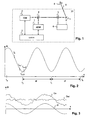
- FIG. 3 shows by way of example a sequence of measured values Da of an absolute distance detection, a sequence of a simultaneously detected relative position dr, and a corrected sequence of absolute distances Dac resulting from the difference Da-dr.
- relative position values are used as correction values dr, which correspond at least approximately to a position of the target at the moment of reflection of the measurement light.
- the method is analogous to the elimination of noise in a sequence of absolute values by averaging or integration applicable.
Abstract
Description
Die Erfindung bezieht sich auf das Gebiet der elektrooptischen Entfernungsmessung. Sie bezieht sich auf ein Verfahren und ein Messgerät zur Messung eines Absolutdistanzwertes gemäss dem Oberbegriff der entsprechenden unabhängigen Patentansprüche.The invention relates to the field of electro-optical distance measurement. It relates to a method and a measuring device for measuring an absolute distance value according to the preamble of the corresponding independent patent claims.
Zur hochauflösenden Messung von Distanzen werden Instrumente zur Bestimmung von Relativdistanzen, beispielsweise Laser-Interferometer verwendet. Dabei läuft ein kollimierter Laserstrahl von einem Messgerät zu einem reflektierenden Ziel. Der gesendete Strahl wird dem reflektierten und im Messgerät empfangenen Strahl überlagert. Bei einer Änderung der Distanz wechselt entsprechend der Interferenz der beiden Strahlen die Intensität der überlagerten Strahlen. Solche Intensitätsänderungen werden detektiert und mittels eines Zählers gezählt. Entsprechend einer Anzahl von Intensitätsänderungen und der Wellenlänge des Laserlichtes ergibt sich die Distanzänderung. Ausgehend von einem bekannten Referenzwert, also einer Absolutdistanz in einer Startposition, lässt sich somit auch eine Absolutdistanz von anderen Positionen ermitteln. Zur Messung von Distanzen zu einem bewegten Reflektor respektive Ziel sind Messgeräte als Tracker ausgestaltet, d.h. dass der Laserstrahl mittels eines drehbaren Spiegels automatisch dem Ziel nachgeführt wird. Dabei werden Elevation und Azimuth des Laserstrahls gemessen, so dass die Bestimmung der Position des Zieles in drei Dimensionen möglich ist. Aufgrund des einfachen Messprinzips kann die Position auch bei Geschwindigkeiten des Ziels von beispielsweise bis zu 10 m/s nachgeführt werden.For the high-resolution measurement of distances, instruments for the determination of relative distances, for example laser interferometers, are used. A collimated laser beam passes from a measuring device to a reflective target. The transmitted beam is superimposed on the reflected beam received in the meter. When the distance is changed, the intensity of the superimposed beams changes according to the interference of the two beams. Such intensity changes are detected and counted by means of a counter. According to a number of intensity changes and the wavelength of the laser light, the distance change results. Starting from a known reference value, ie an absolute distance in a starting position, an absolute distance from other positions can thus also be determined. To measure distances to a moving reflector respectively target measuring devices are designed as trackers, ie that the laser beam by means of a rotatable mirror automatically the goal is tracked. The elevation and azimuth of the laser beam are measured so that the determination of the position of the target in three dimensions is possible. Due to the simple measuring principle, the position can be tracked even at speeds of the target of, for example, up to 10 m / s.
Ein solches Verfahren zu Bestimmung einer Relativdistanz bedingt, dass der Strahl zwischen Messgerät und Ziel nicht unterbrochen wird. Geschieht dies, so werden keine Distanzänderungen mehr erfasst, und ist die Absolutdistanz zwischen Messgerät und Ziel nicht mehr bekannt. Diese Absolutdistanz muss deshalb mit anderen Mitteln neu bestimmt respektive kalibriert werden. Eine solche Kombination eines Absolutdistanzmesseres mit einem Interferometer ist in der
Zur Messung von Absolutdistanzen sind verschiedene Verfahren bekannt, beispielsweise verschiedene Varianten des Fizeau-Verfahrens, wie sie ebenfalls in der genannten
Im Gegensatz zur Messung von Relativdistanzen benötigt aber eine Messung von Absolutdistanzen bei solchen Messdistanzen und Genauigkeiten eine bestimmte minimale Messdauer, während welcher sich die Distanz nicht ändern darf. Deshalb kann das Ziel dabei nicht von einer Bedienperson in der Hand gehalten werden, sondern muss vorübergehend zur Kalibrierung in eine ruhende Halterung abgelegt werden. Dies erzwingt eine zeitaufwendige Unterbrechung der Messungen.In contrast to the measurement of relative distances, however, a measurement of absolute distances at such measurement distances and accuracies requires a certain minimum measurement duration, during which the distance must not change. Therefore, the target can not be held by an operator in the hand, but must be temporarily placed for calibration in a dormant holder. This forces a time-consuming interruption of the measurements.
In
Es ist deshalb Aufgabe der Erfindung, ein Verfahren und ein Messgerät zur Messung eines Absolutdistanzwertes der eingangs genannten Art zu schaffen, welche auch bei einem bewegten Ziel eine präzise Bestimmung einer Absolutdistanz erlauben.It is therefore an object of the invention to provide a method and a measuring device for measuring an absolute distance value of the type mentioned, which allow a precise determination of an absolute distance even with a moving target.
Diese Aufgabe lösen ein Verfahren und ein Messgerät zur Messung eines Absolutdistanzwertes mit den Merkmalen der entsprechenden unabhängigen Patentansprüche.This object is achieved by a method and a measuring device for measuring an absolute distance value with the features of the corresponding independent patent claims.
In dem Verfahren werden in einem Distanzmessgerät, welches sowohl Mittel zur Bestimmung einer absoluten Distanz als auch Mittel zur Bestimmung einer relativen Distanz zwischen dem Messgerät und einem Ziel aufweist, Distanzänderungen, die während einer Bestimmung der absoluten Distanz auftreten, mit dem Mittel zur Bestimmung der relativen Distanz erfasst und bei der Bestimmung der absoluten Distanz berücksichtigt.In the method, in a distance measuring device having both means for determining an absolute distance and means for determining a relative distance between the measuring device and a target, changes in distance which occur during an absolute distance determination are combined with the means for determining the relative Detected distance and taken into account in determining the absolute distance.
Dadurch können Änderungen der Distanz, die während der Messdauer der absoluten Distanz auftreten, also insbesondere Bewegungen des Ziels, kompensiert werden. Es ist nicht mehr erforderlich, dass das Ziel unbewegt gehalten wird. Insbesondere kann das Ziel in der Hand einer Bedienperson gehalten werden, so dass keine wesentliche Unterbrechung einer Messfolge erforderlich ist.As a result, changes in the distance that occur during the measurement period of the absolute distance, ie in particular movements of the target, can be compensated. It is no longer necessary to keep the target motionless. In particular, the target can be held in the hands of an operator, so that no essential interruption of a measurement sequence is required.
In einer bevorzugten Variante der Erfindung ist das Mittel zur Bestimmung der absoluten Distanz zur Ausführung eines iterativen Verfahrens ausgebildet. Das heisst, dass das Verfahren sich schrittweise über mehrere Abtastschritte dem korrekten absoluten Distanzwert nähert. In jedem Abtastschritt wird aus einem Eingabewert ein Ausgabewert ermittelt, welcher vom Eingabewert und von der Distanz abhängig ist. Eine Distanzänderung, die sich zwischen einem ersten Abtastschritt und einem darauffolgenden zweiten Abtastschritt aufgrund einer Bewegung des Ziels und/oder des Messgerätes ergibt, wird mit dem Mittel zur Bestimmung der relativen Distanz erfasst und bei der Bestimmung des Eingabewertes für den zweiten Abtastschritt zur Kompensation der Distanzänderung verwendet.In a preferred variant of the invention, the means for determining the absolute distance for performing an iterative method is formed. This means that the method gradually approaches the correct absolute distance value over several sampling steps. In each sampling step, an output value is determined from an input value, which depends on the input value and on the distance. A distance change that occurs between a first sampling step and a subsequent second sampling step due to a Movement of the target and / or the meter is detected with the means for determining the relative distance and used in the determination of the input value for the second sampling step to compensate for the distance change.
Damit kann das iterative Verfahren konvergieren, ohne durch Distanzänderungen aus der Bahn geworfen zu werden.Thus, the iterative process can converge without being thrown off track by distance changes.
In einer bevorzugten Variante der Erfindung ist das Verfahren zur Messung des absoluten Distanzwertes ein Fizeau-Verfahren. Dabei ist der Eingabewert eine Modulationsfrequenz, die auf einen abgehenden und einen zurückkommenden Lichtstrahl wirkt, und ist der Ausgabewert eine Intensität des zurückkommenden Lichtstrahl nach seiner Modulation.In a preferred variant of the invention, the method for measuring the absolute distance value is a Fizeau method. In this case, the input value is a modulation frequency which acts on an outgoing and a returning light beam, and the output value is an intensity of the returning light beam after its modulation.
In einer weiteren bevorzugten Variante der Erfindung ist das Mittel zur Bestimmung der absoluten Distanz zur Bestimmung einer Mehrzahl von Messwerten für die absolute Distanz ausgebildet. Zur Elimination von Messrauschen werden diese Messwerte gefiltert, beispielsweise durch Integration oder durch Mittelwertbildung. Zur Kompensation von Distanzänderungen zwischen den einzelnen Messungen wird gleichzeitig diese Distanzänderung mit dem Mittel zur Bestimmung der relativen Distanz erfasst, und werden die synchronen Werte der Distanzänderung vor der Filterung von den Messwerten subtrahiert.In a further preferred variant of the invention, the means for determining the absolute distance for determining a plurality of measured values for the absolute distance is formed. To eliminate measurement noise, these measured values are filtered, for example by integration or averaging. To compensate for distance changes between the individual measurements, this distance change is simultaneously detected by the means for determining the relative distance, and the synchronous values of the distance change before the filtering are subtracted from the measured values.
In weiteren bevorzugten Ausführungsformen der Erfindung wird die Messung der Distanzänderung zur Korrektur von Messungen des Absolutwertes mittels
- einem Phasenmessverfahren mit moduliertem Licht,
- eines "chirped"-Signals, kohärent oder inkohärent, oder
- Absolutwert-Interferometrie verwendet. Auch hier gilt, dass jeweils berechnete Werte, die einer absoluten Distanz entsprechen, um gemessene Werte von zeitlich korrespondierenden Relativdistanzen respektive Distanzänderungen korrigiert werden.
Das Messgerät zur Messung eines Absolutdistanzwertes weist ein Mittel zur Bestimmung einer absoluten Distanz entsprechend der Strecke zwischen dem Messgerät und einem Ziel, und ein Mittel zur Bestimmung einer relativen Distanz entlang respektive in Richtung dieser Strecke auf. Dabei ist das Mittel zur Bestimmung der absoluten Distanz zur Durchführung mehrerer einzelner Messschritte ausgebildet, und weist das Messgerät Mittel zur Berücksichtigung von Distanzänderungen bei der Bestimmung der absoluten Distanz auf.
In einer ersten bevorzugten Ausführungsform weist das Messgerät Mittel zur Ausführung eines iterativen Verfahrens mit mehreren Abtastschritten auf, wobei in jedem Abtastschritt aus einem Eingabewert ein Ausgabewert, welcher vom Eingabewert und von der Distanz abhängig ist, messbar ist. Das Mittel zur Bestimmung der relativen Distanz ist zur Bestimmung einer Distanzänderung, die sich zwischen einem Abtastschritt und einem folgenden Abtastschritt ergibt, ausgebildet ist. Das Messgerät weist ferner auf Mittel zur Kompensation der Distanzänderung bei der Bestimmung des Eingabewertes für den folgenden Abtastschritt.
In einer zweiten bevorzugten Ausführungsform weist das Messgerät auf Mittel zum Messen einer Folge von gemessenen Absolutdistanzwerten, Mittel zum Messen einer Folge von mindestens annähernd zeitgleichen Relativdistanzwerten, sowie Mittel zum Korrigieren jedes der Absolutdistanzwerte um den entsprechenden mindestens annähernd zeitgleichen Relativdistanzwert. Dieses Mittel zum Korrigieren bildet eine Folge von korrigierten Absolutdistanzwerten. Aus dieser Folge von korrigierten Absolutdistanzwerten bestimmt ein Mittel zur Auswertung einen repräsentativen Absolutdistanzwert. Dieser repräsentative Absolutdistanzwert ist beispielsweise ein gewichteter Mittelwert oder ein in anderer Weise durch Filterung erhaltener Wert.
Die oben erwähnten Kompensationsmittel oder Mittel zum Auswertung können als Teil des Mittels zur Bestimmung der absoluten Distanz ausgebildet sein, sie können aber auch als Teil einer Verarbeitungseinheit ausgebildet sein, welche Daten von Absolutdistanzmesser und Relativdistanzmesser miteinander kombiniert. Im ersten Fall weist das Messgerät Mittel zur Übergabe von relativen Distanzwerten an das Mittel zur Bestimmung der absoluten Distanz auf. Die relativen Distanzwerte sind dabei jeweils bezogen auf einen beliebigen Startwert entsprechend einer beliebigen Referenzposition.
In einer weiteren bevorzugten Ausführungsform der Erfindung weist das Messgerät Mittel zum Fokussieren des Messstrahles auf das Ziel auf, wie beispielsweise in derEP 0 313 518 A2
- a phase measurement method with modulated light,
- a "chirped" signal, coherent or incoherent, or
- Absolute value interferometry used. Again, calculated values that correspond to an absolute distance are corrected by measured values of temporally corresponding relative distances or distance changes, respectively.
The absolute distance measurement meter comprises means for determining an absolute distance corresponding to the distance between the meter and a target, and means for determining a relative distance along and toward that distance, respectively. In this case, the means for determining the absolute distance for performing a plurality of individual measuring steps is formed, and the measuring device has means for taking into account distance changes in the determination of the absolute distance.
In a first preferred embodiment, the measuring device has means for executing an iterative method with a plurality of sampling steps, wherein in each sampling step an output value, which depends on the input value and on the distance, can be measured from an input value. The means for determining the relative distance is designed to determine a change in distance which results between a scanning step and a following scanning step. The meter further comprises means for compensating the distance change in determining the input value for the following sampling step.
In a second preferred embodiment, the measuring device comprises means for measuring a sequence of measured absolute distance values, means for measuring a series of at least approximately simultaneous relative distance values, and means for correcting each of the absolute distance values by the corresponding at least approximately simultaneous time distance value. This means for correcting forms a sequence of corrected absolute distance values. From this sequence of corrected absolute distance values, a means for evaluation determines a representative one Absolute distance. This representative absolute distance value is, for example, a weighted average or a value otherwise obtained by filtering.
The above-mentioned compensation means or means for evaluation may be formed as part of the means for determining the absolute distance, but they may also be formed as part of a processing unit which combines data from absolute distance meter and relative distance meter together. In the first case, the measuring device has means for transferring relative distance values to the means for determining the absolute distance. The relative distance values are in each case based on an arbitrary starting value corresponding to an arbitrary reference position.
In a further preferred embodiment of the invention, the measuring device has means for focusing the measuring beam on the target, such as in theEP 0 313 518 A2
Im Folgenden wird der Erfindungsgegenstand anhand von bevorzugten Ausführungsbeispielen, welche in den beiliegenden Zeichnungen dargestellt sind, näher erläutert. Es zeigen:
Figur 1- schematisch eine Struktur eines erfindungsgemässen Distanzmessgerätes;
Figur 2- verschiedene bei einem Fizeau-Verfahren vorkommende Grössen; und
Figur 3- bei einem Filterverfahren vorkommende Grössen.
- FIG. 1
- schematically a structure of a distance measuring device according to the invention;
- FIG. 2
- different sizes occurring in a Fizeau process; and
- FIG. 3
- Sizes occurring in a filtering process.
Die in den Zeichnungen verwendeten Bezugszeichen und deren Bedeutung sind in der Bezugszeichenliste zusammengefasst aufgelistet. Grundsätzlich sind in den Figuren gleiche Teile mit gleichen Bezugszeichen versehen.The reference numerals used in the drawings and their meaning are listed in the list of reference numerals. Basically, the same parts are provided with the same reference numerals in the figures.
Die
Das Messgerät 10 weist noch weitere elektrische und optische Mittel auf, wie sie aus dem zitierten Stand der Technik bekannt sind, beispielsweise zur Umlenkung und Kollimierung der Lichtstrahlen. Der Einfachheit halber sind diese aber nicht dargestellt. Das Messgerät 10 oder Teile davon sind in einer bevorzugten Ausführungsform der Erfindung in die Stütze eines motorisierten Theodolits oder in eine Messsäule eingebaut. Beim Einbau in eine Theodoliten-Stütze entfällt der Tracking-Spiegel 7.The measuring
Der Relativdistanzmesser 2 ist vorzugsweise ein Interferometer. Zur relativen Positionsbestimmung mittels eines Interferometers weist dieses einen Up-Down-Zähler auf, der Momentatwerte der Verschiebung des Reflektors registriert. Bei jeder Bewegung des Zieles in Messrichtung um eine halbe Lichtwellenlänge wird ein Zählerpuls, je nach Verschiebungsrichtung im Zähler addiert oder subtrahiert. Bei beispielsweise einem HeNe-Laser findet dies also alle 0.32 Mikrometer statt. Der Zählerstand kann zu beliebigen Zeiten ausgelesen und gespeichert werden. Aufgrund von zwei unterschiedlichen Zählerständen ist eine Relativbewegung dL zwischen den entsprechenden Auslesezeiten bestimmbar als ![]()
dM = Differenz der Zählerstände,
lambda = Wellenlänge des verwendeten Lichtes,
n = Phasenbrechungsindex des Mediums, üblicherweise Luft.The ![]()
dM = difference of meter readings,
lambda = wavelength of the light used,
n = phase refractive index of the medium, usually air.
Damit ist beispielsweise über eine Messdistanz von 0.1 bis 50 m und für Zielgeschwindigkeiten von bis über 10 m/s eine Auflösung von 0.3 bis 2.4 Mikrometern mit einer Genauigkeit von ca. ±0.3ppm möglich.Thus, for example, over a measuring distance of 0.1 to 50 m and for target speeds of more than 10 m / s, a resolution of 0.3 to 2.4 micrometers with an accuracy of approximately ± 0.3 ppm is possible.
Der Absolutdistanzmesser 1 ist vorzugsweise ein Distanzmesser nach dem Fizeau-Prinzip. Der Messlichtstrahl wird beim Fizeausystem durch denselben Modulator zweimal moduliert, einmal als Sendestrahl beim Eintritt in die Messtrecke, und ein zweites Mal als zurückkommender Strahl oder Empfangsstrahl beim Austritt aus der Messtrecke. Bei der Modulation wird beispielsweise eine Polarisation und/oder die Intensität und/oder die Frequenz des Lichts moduliert.The
Dabei ergibt sich, dass sich die Lichtintensität nach der zweiten Modulation oder Rückmodulation in Funktion des Reflektorabstandes und der Modulationsfrequenz periodisch verändert: es entstehen beispielsweise beim linearen Ändern der Modulationsfrequenz und bei fixer Distanz abwechselnd Stellen niedriger und Stellen hoher Lichtintensität A am Ausgang der Demodulation, wie in der 
D = Absolutdistanz
f0, f1 = Frequenzen von Minima
ng = Gruppenbrechungsindex
c0 = Lichtgeschwindigkeit im Vakuum
Add = AdditionskonstanteIt follows that the light intensity after the second modulation or back modulation in function of the reflector distance and the modulation frequency changed periodically: arise, for example, when linearly changing the modulation frequency and fixed distance alternately places lower and high light intensity A points at the output of the demodulation, such as in the
D = absolute distance
f0, f1 = frequencies of minima
ng = group refractive index
c0 = speed of light in a vacuum
Add = addition constant
Für die genaue Bestimmung der Minima wird die Lichtmodulationsfrequenz f vorzugsweise zusätzlich frequenzmoduliert: Beispielsweise wird an einer Grundfrequenz f in einem Band zwischen 2 bis 2.3 GHz eine sinusförmige FrequenzModulation (FM) von 20 kHz mit einem Hub von ca. 500 kHz durchgeführt. Damit wird aus dem detektierten Signal der Photodiode die erste Ableitung gebildet, und an der Minimalstelle des Signals ohne FM-Modulation findet ein Nulldurchgang des FM-modulierten Signals statt. Ein solcher Nulldurchgang ist einfacher als ein Minimum zu detektieren. Die Bestimmung der Amplitude des empfangenen Signals bei einer vorgegebenen Grundfrequenz ― mit oder ohne die zusätzliche FM-Modulation ― wird Folgenden der Einfachheit halber als Abtastung bezeichnet.For the precise determination of the minima, the light modulation frequency f is preferably additionally frequency-modulated: For example, a sinusoidal frequency modulation (FM) of 20 kHz with a stroke of approximately 500 kHz is performed at a fundamental frequency f in a band between 2 and 2.3 GHz. In order to the first derivative is formed from the detected signal of the photodiode, and at the minimum position of the signal without FM modulation, a zero crossing of the FM-modulated signal takes place. Such a zero crossing is easier to detect than a minimum. The determination of the amplitude of the received signal at a given fundamental frequency - with or without the additional FM modulation - is hereinafter referred to as sampling for the sake of simplicity.
Wie oben erwähnt werden zur Bestimmung, der Absolutdistanz mindestens zwei Minima, d.h. zwei benachbarte Nulldurchgänge des demodulierten Signals benötigt. Die entsprechenden Frequenzen sind dabei f0 und f1. Diese Nullstellen werden durch Variation der Grundfrequenz iterativ bestimmt. Dabei wird bei jedem Schritt eine angepasste Frequenzschrittweite verwendet, die möglichst rasch nahe an den gesuchten Nulldurchgang führt, und wobei die letzten Schritte anhand der maximal gewünschten Auflösung, z.B. 1 ppm, bestimmt werden.
berechnet wird. Dies ergibt eine zeitoptimale Abtastfolge von Frequenzschritten, die zur Nulldurchgangsfrequenz respektive Minumumsfrequenz f0, f1, ... führt.As mentioned above, to determine the absolute distance, at least two minima, ie two adjacent zero crossings of the demodulated signal, are needed. The corresponding frequencies are f0 and f1. These zeros are determined iteratively by varying the fundamental frequency. In this case, an adapted frequency step size is used at each step, which leads as quickly as possible to the sought zero crossing, and wherein the last steps are determined by the maximum desired resolution, eg 1 ppm.
is calculated. This results in a time-optimized sampling sequence of frequency steps, which leads to the zero-crossing frequency or minumum frequency f0, f1,.
Damit ist beispielsweise über eine Messdistanz von 1 bis 100 m und für stationäre Ziele eine Auflösung von ca. 1 Mikrometer mit einer Genauigkeit von kleiner als ±25 Mikrometern möglich. Die Messzeit für eine erste Distanzbestimmung dauert beispielsweise 200 Millisekunden, davon ausgehend können anschliessend durch repetitive Messung an einer Nullstelle ca. zehn Werte pro Sekunde ermittelt werden. Verschiedene Vorrichtungen und Verfahren für eine solche Distanzmessung sind in der eingangs erwähnten
Die Frequenzschritte werden, indem sie sich dem Nulldurchgang nähern, zunehmend kleiner, was auch immer kleineren Schritten der zu messenden Distanz entspricht. Da diese iterative Annäherung eine gewisse Zeit erfordert, darf sich gemäss dem Stand der Technik die Distanz während dieser Zeit nicht ändern, weil sonst die Iteration an einer völlig falschen Stelle fortfahren würde und die Iteration der Distanzänderung in der Regel gar nicht schnell genug folgen könnte.The frequency steps become progressively smaller as they approach the zero crossing, whichever corresponds to smaller steps of the distance to be measured. Since this iterative approximation requires a certain amount of time, according to the prior art, the distance during this time may not change, because otherwise the iteration would continue in a completely wrong place and the iteration of the distance change would usually not be able to follow fast enough.
Dasselbe Problem stellt sich auch vor und nach der beschriebenen Iteration: Vorher kann beispielsweise eine Grobmessung der Distanz erfolgen, indem mehrere Eingangswerte innerhalb einer vorgegebenen Bandbreite abgetastet werden, wie weiter unten noch beschrieben wird. Nach einer ersten Bestimmung des Minimums wird diese vorzugsweise einige Male wiederholt, um aus den Ergebnissen einen Mittelwert als Nulldurchgangsfrequenz f0, f1 zu bestimmen. Insgesamt werden beispielsweise 20 Abtastungen für die Grobmessung, ca. 20 Abtastungen für die Iteration und 10 Abtastungen für die wiederholte Bestimmung des Minimums benötigt, was bei 1 ms pro Abtastung eine Dauer von 50 ms ergibt.The same problem also arises before and after the described iteration: Before, for example, a coarse measurement of the distance can be made by scanning a plurality of input values within a predetermined bandwidth, as will be described below. After a first determination of the minimum, it is preferably repeated a few times in order to determine from the results an average value as the zero-crossing frequency f0, f1. In total, for example, 20 samples are needed for the coarse measurement, about 20 samples for the iteration and 10 samples for the repeated determination of the minimum, giving a duration of 50 ms at 1 ms per sample.
Deshalb wird gleichzeitig mit den einzelnen Abtastungen, insbesondere während der Iteration, eine Bestimmung der relativen Distanzänderung durchgeführt, beispielsweise mit Hilfe eines interferometrischen Verfahrens. Ein neuer Iterationsschritt wird entsprechend der derart gemessenen Relativbewegung des Ziels zwischen der letzen und der neuen Abtastung korrigiert.Therefore, a determination of the relative distance change is performed simultaneously with the individual samples, in particular during the iteration, for example by means of an interferometric method. A new iteration step is corrected according to the thus measured relative movement of the target between the last and the new scan.
Bei einem neuen Messvorgang wird daher zur Bestimmung der Absolutdistanz zu Beginn der Messung eine Grobmessung der Distanz erfolgen. Dazu wird der Nullstellenabstand f 0 - f 1 und daraus die Grobdistanz 
Der Korrekturwert der Frequenz Δf berechnet sich aus der relativen Bewegung Δs zu 
Bei der vorgängigen Grobmessung und bei der anschliessenden wiederholten Bestimmung des Minimums wird die Kompensation der Relativbewegungen ebenfalls vorgenommen. Die Bestimmung des Minimums wird für mindestens zwei unterschiedliche Frequenzen f0 und f1 durchgeführt. Da nach dem Vorliegen dieser Werte auch die anschliessende Berechnung der entsprechenden Distanz D eine gewisse Rechenzeit benötigt, wird die Relativposition auch während dieser Rechenzeit weiter verfolgt. Nachdem die Distanz bekannt ist, wird sie um die in der Zwischenzeit aufsummierte aktuelle Distanzänderung korrigiert und ab dann als Referenzwert für den Relativdistanzmesser 2 verwendet. Beispielsweise wird dazu der Zähler im Relativdistanzmesser 2 entsprechend dem Referenzwert gesetzt, oder ein konstanter Offset entsprechend dem Referenzwert wird zur Distanz addiert.In the case of the preliminary coarse measurement and the subsequent repeated determination of the minimum, the compensation of the relative movements is likewise carried out. The determination of the minimum is performed for at least two different frequencies f0 and f1. Since, after the presence of these values, the subsequent calculation of the corresponding distance D requires a certain computing time, the relative position is also tracked during this computing time. After the distance is known, it is corrected by the current distance change accumulated in the meantime and then used as the reference value for the
Zusammengefasst kann gesagt werden, dass für die Abtastungen für die verschiedenen Messungen vorzugsweise während der gesamten Messdauer jeweils berechnete Werte, die einer absoluten Distanz entsprechen, um gemessene Werte von zeitlich korrespondierenden Relativdistanzen korrigiert werden.In summary, it can be said that for the samples for the different measurements, preferably calculated values which correspond to an absolute distance are corrected by measured values of temporally corresponding relative distances during the entire measurement duration.
Damit wird trotz einer Bewegung des Reflektors das Verfahren im Prinzip genau so gut und schnell konvergieren wie ohne Bewegung.Thus, in spite of a movement of the reflector, the method will in principle converge just as well and fast as without movement.
Nach dem Messablauf zur Bestimmung des absoluten Distanzwertes wird dieser der relativen Distanzbestimmung, also z.B. dem Interferometer übergeben. Danach folgt der Distanzwert über den Interferometer-Messwert auch schnellen Bewegungen, beispielsweise mit über 5 m/s.After the measurement procedure for the determination of the absolute distance value, this value is determined for the relative distance determination, e.g. handed over to the interferometer. Thereafter, the distance value via the interferometer measured value also follows fast movements, for example with more than 5 m / s.
In einer weiteren bevorzugten Ausführungsform der Erfindung verwendet der Absolutdistanzmesser nach dem Fizeau-Prinzip zwei Lichtwellenlängen, es wird beispielsweise zusätzlich zu der erwähnten 780 nm Laserdiode noch eine Laserdiode mit einer Wellenlänge von beispielsweise unter 450 nm ("blau") verwendet, und deren Licht in den Messstrahl eingekoppelt. Es werden somit zwei Distanzmessungen mit unterschiedlichen Wellenlängen durchgeführt, was eine Kompensation respektive Elimination des Brechungsindexes der Luft ermöglicht.In a further preferred embodiment of the invention, the absolute distance meter according to the Fizeau principle uses two wavelengths of light, for example, in addition to the mentioned 780 nm laser diode still a laser diode having a wavelength of, for example, below 450 nm ("blue") is used, and their light in coupled the measuring beam. Thus, two distance measurements with different wavelengths are carried out, which enables a compensation or elimination of the refractive index of the air.
In einer anderen bevorzugten Ausführungsform der Erfindung wird zur Bestimmung der absoluten Entfernung eine Laufzeitmessung durchgeführt. Um die Werte mehrerer Laufzeitmessungen zur Kompensation von Messungenauigkeiten zusammenzufassen, beispielsweise durch Mittelwertbildung, werden diese Werte nach Massgabe der Relativbewegung korrigiert.
Ganz allgemein ist das Verfahren in analoger Weise zur Elimination von Rauschen in einer Folge von Absolutwerten durch Mittelwertbildung respektive Integration anwendbar.In general, the method is analogous to the elimination of noise in a sequence of absolute values by averaging or integration applicable.
In weiteren bevorzugten Ausführungsformen der Erfindung wird die Messung der Distanzänderung zur Korrektur bei der Messung des Absolutwertes mittels
- Phasenmessverfahren mit moduliertem Licht,
- eines "chirped"-Signals, kohärent oder inkohärent, oder
- Absolutwert-Interferometrie
- Phase measurement method with modulated light,
- a "chirped" signal, coherent or incoherent, or
- Absolute value interferometry
- 11
- AbsolutdistanzmesserAbsolute Distance Meter
- 22
- RelativdistanzmesserRelative distance meter
- 33
- Kontrolleinheitcontrol unit
- 44
- erster Strahlteilerfirst beam splitter
- 55
- zweiter Strahlteilersecond beam splitter
- 66
- Tracking-ReglerTracking Controller
- 77
- Tracking-SpiegelTracking mirror
- 88th
- Reflektorreflector
- 99
- Streckeroute
- 1010
- Messgerätgauge
Claims (9)
- Method for measuring an absolute distance corresponding with a range (9) between a measuring device (10) and a target (8), wherein several individual measuring steps are executed by means of an absolute distance meter (1) for measuring the absolute distance, characterized in that at least approximately simultaneously with these individual measuring steps, a distance variation between the measuring device (10) and the target (8) is measured as a transient value of the target displacement by means of a relative distance meter (2) and said distance variation is taken into account during the determination of the absolute distance, by the absolute distance meter (1) arriving at the absolute distance value iteratively through several sampling steps, and distance variations between the measuring device (10) and the target (8) arising between two sampling steps being detected by the relative distance meter (2) and incorporated in the determination of the absolute distance meter (1) in the later of the two sampling steps.
- Method according to claim 1, characterized in that an iterative method of several sampling steps is applied for measuring the absolute distance value, wherein during each sampling step an output value (A), being an intensity (A) of the modulated returning ray and dependent on the input value (fn, fn+1, fn+2, ...) and on the distance, is generated and measured from an input value (fn, fn+1, fn+2, ...), being a modulation frequency acting upon a departing and a returning ray, and wherein each distance variation occurring between one sampling step and the next is measured and used for the compensation of the distance variation during determination of the input value (fn+1, fn+2, fn+3, ...) for the following sampling step.
- Method according to any one of claims 1 or 2, characterized in that the frequency fntheor of an iteration step, determined theoretically according to the iterative method, is corrected according to a measured distance variation Δs in the following manner in order to determine an actually used frequency fn

wherein
- Method according to claim 1, characterized in that it comprises the following steps:■ measuring a sequence of absolute distance values,■ measuring a sequence of at least approximately simultaneous relative distance values,■ correcting each one of the absolute distance values by the corresponding, at least approximately simultaneous relative distance value in order to form a sequence of corrected absolute distance values, and■ evaluating the sequence of corrected absolute distance values in order to determine a representative absolute distance.
- Method according to claim 4, characterized in that the evaluation involves averaging, integration or another kind of filtering.
- Measuring device (10) for measuring an absolute distance, comprising an absolute distance meter (1) for the determination of an absolute distance corresponding to a range (9) between the measuring device (10) and a target (8), characterized in that the measuring device (10) comprises a relative distance meter (2) for the determination of a distance variation between the measuring device (10) and a target (8) as a transient value of the target's displacement, that the absolute distance meter (1) is designed to generate the absolute distance value iteratively across a number of individual measuring steps, and that the measuring device (10) comprises means to take into account the distance variations between the measuring device (10) and the target (8), arising between two sampling steps and detected by the relative distance meter (2), during the determination of the absolute distance by the absolute distance meter (1) in the later of the two sampling steps.
- Measuring device (10) according to claim 6, characterized in that it comprises means (1) to execute an iterative Fizeau method of a number of sampling steps, wherein during each sampling step an output value (A), being an intensity (A) of the modulated returning ray that is dependent on the input value and on the distance, can be measured from an input value, being a modulation frequency acting upon a departing and a returning ray, and wherein the means (2) to determine the relative distance is designed to determine a distance variation occurring between one sampling step and the next, and the measuring device (10) comprises means to compensate the distance variation during the determination of the input value for the following sampling step.
- Measuring device (10) according to claim 6, characterized in that it comprises means (1) to measure a sequence of absolute distance values, means (2) to measure a sequence of at least approximately simultaneous relative distance values, means to correct each absolute distance value by the corresponding, at least approximately simultaneous relative distance value in order to form a sequence of corrected absolute distance values, and means to evaluate the sequence of corrected absolute distance values in order to determine a representative absolute distance value.
- Measuring device (10) according to any one of claims 6 to 8, characterized in that it comprises means to transmit relative distance values to the means (1) to determine the absolute distance.
Priority Applications (9)
| Application Number | Priority Date | Filing Date | Title |
|---|---|---|---|
| DE502004011107T DE502004011107D1 (en) | 2004-10-13 | 2004-10-13 | Method and measuring device for measuring an absolute distance value |
| AT04405638T ATE466298T1 (en) | 2004-10-13 | 2004-10-13 | METHOD AND MEASURING DEVICE FOR MEASURING AN ABSOLUTE DISTANCE VALUE |
| EP04405638A EP1647838B1 (en) | 2004-10-13 | 2004-10-13 | Method and apparatus for absolute distance measurement |
| AU2005294044A AU2005294044B2 (en) | 2004-10-13 | 2005-09-29 | Method and measuring device for measuring an absolute distance |
| JP2007535974A JP4995089B2 (en) | 2004-10-13 | 2005-09-29 | Method and apparatus for measuring absolute distance values |
| PCT/CH2005/000560 WO2006039820A1 (en) | 2004-10-13 | 2005-09-29 | Method and measuring device for measuring an absolute distance |
| CNB2005800425689A CN100549726C (en) | 2004-10-13 | 2005-09-29 | Be used to measure the method and the measurement mechanism of absolute distance |
| CA2584347A CA2584347C (en) | 2004-10-13 | 2005-09-29 | Method and measuring device for measuring an absolute distance |
| US11/577,159 US7609387B2 (en) | 2004-10-13 | 2005-09-29 | Method and measuring device for measuring an absolute distance |
Applications Claiming Priority (1)
| Application Number | Priority Date | Filing Date | Title |
|---|---|---|---|
| EP04405638A EP1647838B1 (en) | 2004-10-13 | 2004-10-13 | Method and apparatus for absolute distance measurement |
Publications (2)
| Publication Number | Publication Date |
|---|---|
| EP1647838A1 EP1647838A1 (en) | 2006-04-19 |
| EP1647838B1 true EP1647838B1 (en) | 2010-04-28 |
Family
ID=34932315
Family Applications (1)
| Application Number | Title | Priority Date | Filing Date |
|---|---|---|---|
| EP04405638A Active EP1647838B1 (en) | 2004-10-13 | 2004-10-13 | Method and apparatus for absolute distance measurement |
Country Status (9)
| Country | Link |
|---|---|
| US (1) | US7609387B2 (en) |
| EP (1) | EP1647838B1 (en) |
| JP (1) | JP4995089B2 (en) |
| CN (1) | CN100549726C (en) |
| AT (1) | ATE466298T1 (en) |
| AU (1) | AU2005294044B2 (en) |
| CA (1) | CA2584347C (en) |
| DE (1) | DE502004011107D1 (en) |
| WO (1) | WO2006039820A1 (en) |
Families Citing this family (11)
| Publication number | Priority date | Publication date | Assignee | Title |
|---|---|---|---|---|
| JP2007309677A (en) * | 2006-05-16 | 2007-11-29 | Mitsutoyo Corp | Method of estimating absolute distance in tracking laser interferometer, and tracking laser interferometer |
| US8767215B2 (en) * | 2007-06-18 | 2014-07-01 | Leddartech Inc. | Method for detecting objects with light |
| US8305563B2 (en) | 2008-02-19 | 2012-11-06 | Leica Geosystems Ag | Electro-optical distance-measuring unit |
| WO2010148526A1 (en) | 2009-06-23 | 2010-12-29 | Leica Geosystem Ag | Tracking method and measuring system having a laser tracker |
| EP2653908A1 (en) | 2012-04-16 | 2013-10-23 | Leica Geosystems AG | Electro-optic modulator and electro-optic distance-measuring device |
| EP2653884A1 (en) * | 2012-04-16 | 2013-10-23 | Leica Geosystems AG | Electro-optic distance-measuring device |
| EP2662702A1 (en) * | 2012-05-07 | 2013-11-13 | Leica Geosystems AG | Laser tracker with interferometer and absolute distance measuring unit and calibration method for a laser tracker |
| CN103499338A (en) * | 2013-05-14 | 2014-01-08 | 罗江临 | Method for guaranteeing measuring range of laser range measurer and improving measuring precision |
| KR102144541B1 (en) * | 2014-05-08 | 2020-08-18 | 주식회사 히타치엘지 데이터 스토리지 코리아 | Apparatus for sensing distances of two directions |
| EP3346287A4 (en) * | 2015-09-01 | 2019-02-27 | The University Of Tokyo | Motion detection device and three-dimensional shape measurement device using same |
| TWI595252B (en) * | 2016-05-10 | 2017-08-11 | 財團法人工業技術研究院 | Distance measurement device and distance measuring method thereof |
Family Cites Families (10)
| Publication number | Priority date | Publication date | Assignee | Title |
|---|---|---|---|---|
| US4606638A (en) * | 1983-11-03 | 1986-08-19 | Zygo Corporation | Distance measuring interferometer and method of use |
| US4714339B2 (en) * | 1986-02-28 | 2000-05-23 | Us Commerce | Three and five axis laser tracking systems |
| JPH0430484Y2 (en) * | 1986-09-11 | 1992-07-23 | ||
| CH674675A5 (en) * | 1987-10-23 | 1990-06-29 | Kern & Co Ag | |
| DE4314488C2 (en) * | 1993-05-03 | 1997-11-20 | Heidenhain Gmbh Dr Johannes | Interferometric measuring method for absolute measurements as well as a suitable laser interferometer arrangement |
| DE19542490C1 (en) * | 1995-11-15 | 1997-06-05 | Leica Ag | Electro-optical measuring device for absolute distances |
| WO2000063645A1 (en) * | 1999-04-19 | 2000-10-26 | Leica Geosystems Ag | Indirect position determination with the aid of a tracker |
| EP1407291B1 (en) * | 2001-04-10 | 2010-12-15 | Faro Technologies Inc. | Chopper-stabilized absolute distance meter |
| DE60100085T2 (en) | 2001-04-12 | 2003-05-28 | Agilent Technologies Inc | Device for the calibration of wavelength measuring devices |
| US7285793B2 (en) * | 2005-07-15 | 2007-10-23 | Verisurf Software, Inc. | Coordinate tracking system, apparatus and method of use |
-
2004
- 2004-10-13 DE DE502004011107T patent/DE502004011107D1/en active Active
- 2004-10-13 AT AT04405638T patent/ATE466298T1/en not_active IP Right Cessation
- 2004-10-13 EP EP04405638A patent/EP1647838B1/en active Active
-
2005
- 2005-09-29 US US11/577,159 patent/US7609387B2/en active Active
- 2005-09-29 CA CA2584347A patent/CA2584347C/en not_active Expired - Fee Related
- 2005-09-29 CN CNB2005800425689A patent/CN100549726C/en active Active
- 2005-09-29 JP JP2007535974A patent/JP4995089B2/en not_active Expired - Fee Related
- 2005-09-29 WO PCT/CH2005/000560 patent/WO2006039820A1/en active Application Filing
- 2005-09-29 AU AU2005294044A patent/AU2005294044B2/en not_active Ceased
Also Published As
| Publication number | Publication date |
|---|---|
| US7609387B2 (en) | 2009-10-27 |
| JP2008516246A (en) | 2008-05-15 |
| US20090033945A1 (en) | 2009-02-05 |
| EP1647838A1 (en) | 2006-04-19 |
| AU2005294044B2 (en) | 2010-05-27 |
| CA2584347C (en) | 2013-06-11 |
| CN100549726C (en) | 2009-10-14 |
| AU2005294044A1 (en) | 2006-04-20 |
| CN101076743A (en) | 2007-11-21 |
| ATE466298T1 (en) | 2010-05-15 |
| JP4995089B2 (en) | 2012-08-08 |
| CA2584347A1 (en) | 2006-04-20 |
| DE502004011107D1 (en) | 2010-06-10 |
| WO2006039820A1 (en) | 2006-04-20 |
Similar Documents
| Publication | Publication Date | Title |
|---|---|---|
| WO2006039820A1 (en) | Method and measuring device for measuring an absolute distance | |
| EP1851504B1 (en) | Phase noise compensation for an interferometer measuring absolute distance | |
| DE2235318C3 (en) | Method for opto-electronic measurement of distance and height difference and arrangement for carrying out the method | |
| DE19542490C1 (en) | Electro-optical measuring device for absolute distances | |
| EP2917763B1 (en) | Lidar measuring system and lidar measuring process | |
| DE19637777C1 (en) | Method of error correction for heterodyne transformer | |
| DE102004037137B4 (en) | Method and device for distance measurement | |
| DE112019002028T5 (en) | LIDAR DETECTION ARRANGEMENTS | |
| DE19721843C1 (en) | Interferometric measuring device | |
| EP0428027B1 (en) | Optical distance measurement device | |
| CH674675A5 (en) | ||
| EP1637902A1 (en) | Method and device for interferometric radar measurement | |
| DE2757585C3 (en) | Device for the automatic alignment of a laser beam on a target | |
| EP0075032B1 (en) | Method for interferometric surface topography | |
| EP0670467A1 (en) | Interferometer | |
| EP2985592A1 (en) | Absorption spectrometer and method for measuring the concentration of an interesting gas component of a measuring gas | |
| EP3581962A1 (en) | Dual beam fmcw distance measuring method with compensation of a speed-dependent distance measuring fault | |
| DE102010062842B4 (en) | Method and device for determining the absolute position of an object | |
| DE2701858A1 (en) | MEASURING METHOD AND DEVICE FOR DISTANCE CHANGES | |
| DE69627419T2 (en) | Fourier spectrometer with dichroic Michelson mirrors for two wavelength bands | |
| DE4427352C1 (en) | High resolution distance measurement using FMCW laser radar | |
| DE69938402T2 (en) | An interference method and apparatus for measuring the phase shift of two light beams emanating from a single polarized source. | |
| DE19913049A1 (en) | Method and device for determining speed | |
| EP0346601B1 (en) | Method and apparatus for measuring fluid flow velocity, in particular in a wind tunnel | |
| DE2163200A1 (en) | DEVICE FOR CONTACTLESS MEASUREMENT |
Legal Events
| Date | Code | Title | Description |
|---|---|---|---|
| PUAI | Public reference made under article 153(3) epc to a published international application that has entered the european phase |
Free format text: ORIGINAL CODE: 0009012 |
|
| AK | Designated contracting states |
Kind code of ref document: A1 Designated state(s): AT BE BG CH CY CZ DE DK EE ES FI FR GB GR HU IE IT LI LU MC NL PL PT RO SE SI SK TR |
|
| AX | Request for extension of the european patent |
Extension state: AL HR LT LV MK |
|
| 17P | Request for examination filed |
Effective date: 20060814 |
|
| AKX | Designation fees paid |
Designated state(s): AT BE BG CH CY CZ DE DK EE ES FI FR GB GR HU IE IT LI LU MC NL PL PT RO SE SI SK TR |
|
| 17Q | First examination report despatched |
Effective date: 20080619 |
|
| GRAP | Despatch of communication of intention to grant a patent |
Free format text: ORIGINAL CODE: EPIDOSNIGR1 |
|
| GRAJ | Information related to disapproval of communication of intention to grant by the applicant or resumption of examination proceedings by the epo deleted |
Free format text: ORIGINAL CODE: EPIDOSDIGR1 |
|
| GRAP | Despatch of communication of intention to grant a patent |
Free format text: ORIGINAL CODE: EPIDOSNIGR1 |
|
| RIN1 | Information on inventor provided before grant (corrected) |
Inventor name: MEIER, DIETRICH |
|
| GRAS | Grant fee paid |
Free format text: ORIGINAL CODE: EPIDOSNIGR3 |
|
| GRAA | (expected) grant |
Free format text: ORIGINAL CODE: 0009210 |
|
| AK | Designated contracting states |
Kind code of ref document: B1 Designated state(s): AT BE BG CH CY CZ DE DK EE ES FI FR GB GR HU IE IT LI LU MC NL PL PT RO SE SI SK TR |
|
| REG | Reference to a national code |
Ref country code: GB Ref legal event code: FG4D Free format text: NOT ENGLISH |
|
| REG | Reference to a national code |
Ref country code: CH Ref legal event code: EP |
|
| REG | Reference to a national code |
Ref country code: IE Ref legal event code: FG4D Free format text: LANGUAGE OF EP DOCUMENT: GERMAN |
|
| REF | Corresponds to: |
Ref document number: 502004011107 Country of ref document: DE Date of ref document: 20100610 Kind code of ref document: P |
|
| REG | Reference to a national code |
Ref country code: CH Ref legal event code: NV Representative=s name: FREI PATENTANWALTSBUERO AG |
|
| REG | Reference to a national code |
Ref country code: NL Ref legal event code: T3 |
|
| REG | Reference to a national code |
Ref country code: SE Ref legal event code: TRGR |
|
| PG25 | Lapsed in a contracting state [announced via postgrant information from national office to epo] |
Ref country code: ES Free format text: LAPSE BECAUSE OF FAILURE TO SUBMIT A TRANSLATION OF THE DESCRIPTION OR TO PAY THE FEE WITHIN THE PRESCRIBED TIME-LIMIT Effective date: 20100808 |
|
| REG | Reference to a national code |
Ref country code: IE Ref legal event code: FD4D |
|
| PG25 | Lapsed in a contracting state [announced via postgrant information from national office to epo] |
Ref country code: SI Free format text: LAPSE BECAUSE OF FAILURE TO SUBMIT A TRANSLATION OF THE DESCRIPTION OR TO PAY THE FEE WITHIN THE PRESCRIBED TIME-LIMIT Effective date: 20100428 Ref country code: FI Free format text: LAPSE BECAUSE OF FAILURE TO SUBMIT A TRANSLATION OF THE DESCRIPTION OR TO PAY THE FEE WITHIN THE PRESCRIBED TIME-LIMIT Effective date: 20100428 |
|
| PG25 | Lapsed in a contracting state [announced via postgrant information from national office to epo] |
Ref country code: GR Free format text: LAPSE BECAUSE OF FAILURE TO SUBMIT A TRANSLATION OF THE DESCRIPTION OR TO PAY THE FEE WITHIN THE PRESCRIBED TIME-LIMIT Effective date: 20100729 Ref country code: PL Free format text: LAPSE BECAUSE OF FAILURE TO SUBMIT A TRANSLATION OF THE DESCRIPTION OR TO PAY THE FEE WITHIN THE PRESCRIBED TIME-LIMIT Effective date: 20100428 Ref country code: CY Free format text: LAPSE BECAUSE OF FAILURE TO SUBMIT A TRANSLATION OF THE DESCRIPTION OR TO PAY THE FEE WITHIN THE PRESCRIBED TIME-LIMIT Effective date: 20100428 |
|
| PG25 | Lapsed in a contracting state [announced via postgrant information from national office to epo] |
Ref country code: DK Free format text: LAPSE BECAUSE OF FAILURE TO SUBMIT A TRANSLATION OF THE DESCRIPTION OR TO PAY THE FEE WITHIN THE PRESCRIBED TIME-LIMIT Effective date: 20100428 Ref country code: EE Free format text: LAPSE BECAUSE OF FAILURE TO SUBMIT A TRANSLATION OF THE DESCRIPTION OR TO PAY THE FEE WITHIN THE PRESCRIBED TIME-LIMIT Effective date: 20100428 Ref country code: IE Free format text: LAPSE BECAUSE OF FAILURE TO SUBMIT A TRANSLATION OF THE DESCRIPTION OR TO PAY THE FEE WITHIN THE PRESCRIBED TIME-LIMIT Effective date: 20100428 Ref country code: PT Free format text: LAPSE BECAUSE OF FAILURE TO SUBMIT A TRANSLATION OF THE DESCRIPTION OR TO PAY THE FEE WITHIN THE PRESCRIBED TIME-LIMIT Effective date: 20100830 |
|
| PG25 | Lapsed in a contracting state [announced via postgrant information from national office to epo] |
Ref country code: CZ Free format text: LAPSE BECAUSE OF FAILURE TO SUBMIT A TRANSLATION OF THE DESCRIPTION OR TO PAY THE FEE WITHIN THE PRESCRIBED TIME-LIMIT Effective date: 20100428 Ref country code: RO Free format text: LAPSE BECAUSE OF FAILURE TO SUBMIT A TRANSLATION OF THE DESCRIPTION OR TO PAY THE FEE WITHIN THE PRESCRIBED TIME-LIMIT Effective date: 20100428 Ref country code: SK Free format text: LAPSE BECAUSE OF FAILURE TO SUBMIT A TRANSLATION OF THE DESCRIPTION OR TO PAY THE FEE WITHIN THE PRESCRIBED TIME-LIMIT Effective date: 20100428 |
|
| PLBE | No opposition filed within time limit |
Free format text: ORIGINAL CODE: 0009261 |
|
| STAA | Information on the status of an ep patent application or granted ep patent |
Free format text: STATUS: NO OPPOSITION FILED WITHIN TIME LIMIT |
|
| PG25 | Lapsed in a contracting state [announced via postgrant information from national office to epo] |
Ref country code: IT Free format text: LAPSE BECAUSE OF FAILURE TO SUBMIT A TRANSLATION OF THE DESCRIPTION OR TO PAY THE FEE WITHIN THE PRESCRIBED TIME-LIMIT Effective date: 20100428 |
|
| 26N | No opposition filed |
Effective date: 20110131 |
|
| PG25 | Lapsed in a contracting state [announced via postgrant information from national office to epo] |
Ref country code: MC Free format text: LAPSE BECAUSE OF NON-PAYMENT OF DUE FEES Effective date: 20101031 |
|
| REG | Reference to a national code |
Ref country code: AT Ref legal event code: MM01 Ref document number: 466298 Country of ref document: AT Kind code of ref document: T Effective date: 20101013 |
|
| PG25 | Lapsed in a contracting state [announced via postgrant information from national office to epo] |
Ref country code: AT Free format text: LAPSE BECAUSE OF NON-PAYMENT OF DUE FEES Effective date: 20101013 |
|
| PG25 | Lapsed in a contracting state [announced via postgrant information from national office to epo] |
Ref country code: LU Free format text: LAPSE BECAUSE OF NON-PAYMENT OF DUE FEES Effective date: 20101013 Ref country code: BG Free format text: LAPSE BECAUSE OF FAILURE TO SUBMIT A TRANSLATION OF THE DESCRIPTION OR TO PAY THE FEE WITHIN THE PRESCRIBED TIME-LIMIT Effective date: 20100428 Ref country code: HU Free format text: LAPSE BECAUSE OF FAILURE TO SUBMIT A TRANSLATION OF THE DESCRIPTION OR TO PAY THE FEE WITHIN THE PRESCRIBED TIME-LIMIT Effective date: 20101029 |
|
| PG25 | Lapsed in a contracting state [announced via postgrant information from national office to epo] |
Ref country code: TR Free format text: LAPSE BECAUSE OF FAILURE TO SUBMIT A TRANSLATION OF THE DESCRIPTION OR TO PAY THE FEE WITHIN THE PRESCRIBED TIME-LIMIT Effective date: 20100428 |
|
| PG25 | Lapsed in a contracting state [announced via postgrant information from national office to epo] |
Ref country code: BG Free format text: LAPSE BECAUSE OF FAILURE TO SUBMIT A TRANSLATION OF THE DESCRIPTION OR TO PAY THE FEE WITHIN THE PRESCRIBED TIME-LIMIT Effective date: 20100728 |
|
| REG | Reference to a national code |
Ref country code: CH Ref legal event code: NV Representative=s name: KAMINSKI HARMANN PATENTANWAELTE AG, LI |
|
| REG | Reference to a national code |
Ref country code: FR Ref legal event code: PLFP Year of fee payment: 12 |
|
| REG | Reference to a national code |
Ref country code: DE Ref legal event code: R082 Ref document number: 502004011107 Country of ref document: DE Representative=s name: KAMINSKI HARMANN PATENTANWAELTE AG, LI |
|
| REG | Reference to a national code |
Ref country code: FR Ref legal event code: PLFP Year of fee payment: 13 |
|
| REG | Reference to a national code |
Ref country code: FR Ref legal event code: PLFP Year of fee payment: 14 |
|
| REG | Reference to a national code |
Ref country code: FR Ref legal event code: PLFP Year of fee payment: 15 |
|
| PGFP | Annual fee paid to national office [announced via postgrant information from national office to epo] |
Ref country code: NL Payment date: 20191021 Year of fee payment: 16 Ref country code: SE Payment date: 20191021 Year of fee payment: 16 |
|
| PGFP | Annual fee paid to national office [announced via postgrant information from national office to epo] |
Ref country code: BE Payment date: 20191021 Year of fee payment: 16 |
|
| PGFP | Annual fee paid to national office [announced via postgrant information from national office to epo] |
Ref country code: CH Payment date: 20191021 Year of fee payment: 16 |
|
| REG | Reference to a national code |
Ref country code: CH Ref legal event code: PL |
|
| REG | Reference to a national code |
Ref country code: SE Ref legal event code: EUG |
|
| REG | Reference to a national code |
Ref country code: NL Ref legal event code: MM Effective date: 20201101 |
|
| REG | Reference to a national code |
Ref country code: BE Ref legal event code: MM Effective date: 20201031 |
|
| PG25 | Lapsed in a contracting state [announced via postgrant information from national office to epo] |
Ref country code: NL Free format text: LAPSE BECAUSE OF NON-PAYMENT OF DUE FEES Effective date: 20201101 |
|
| PG25 | Lapsed in a contracting state [announced via postgrant information from national office to epo] |
Ref country code: BE Free format text: LAPSE BECAUSE OF NON-PAYMENT OF DUE FEES Effective date: 20201031 Ref country code: CH Free format text: LAPSE BECAUSE OF NON-PAYMENT OF DUE FEES Effective date: 20201031 Ref country code: SE Free format text: LAPSE BECAUSE OF NON-PAYMENT OF DUE FEES Effective date: 20201014 Ref country code: LI Free format text: LAPSE BECAUSE OF NON-PAYMENT OF DUE FEES Effective date: 20201031 |
|
| PGFP | Annual fee paid to national office [announced via postgrant information from national office to epo] |
Ref country code: GB Payment date: 20231020 Year of fee payment: 20 |
|
| PGFP | Annual fee paid to national office [announced via postgrant information from national office to epo] |
Ref country code: FR Payment date: 20231023 Year of fee payment: 20 Ref country code: DE Payment date: 20231020 Year of fee payment: 20 |