EP1647347A2 - Méthode et appareil pour usinage par décharge électrique de pièces de travail. - Google Patents
Méthode et appareil pour usinage par décharge électrique de pièces de travail. Download PDFInfo
- Publication number
- EP1647347A2 EP1647347A2 EP05109273A EP05109273A EP1647347A2 EP 1647347 A2 EP1647347 A2 EP 1647347A2 EP 05109273 A EP05109273 A EP 05109273A EP 05109273 A EP05109273 A EP 05109273A EP 1647347 A2 EP1647347 A2 EP 1647347A2
- Authority
- EP
- European Patent Office
- Prior art keywords
- erosion
- wire
- workpiece
- feed
- erosion wire
- Prior art date
- Legal status (The legal status is an assumption and is not a legal conclusion. Google has not performed a legal analysis and makes no representation as to the accuracy of the status listed.)
- Withdrawn
Links
Images


Classifications
-
- B—PERFORMING OPERATIONS; TRANSPORTING
- B23—MACHINE TOOLS; METAL-WORKING NOT OTHERWISE PROVIDED FOR
- B23H—WORKING OF METAL BY THE ACTION OF A HIGH CONCENTRATION OF ELECTRIC CURRENT ON A WORKPIECE USING AN ELECTRODE WHICH TAKES THE PLACE OF A TOOL; SUCH WORKING COMBINED WITH OTHER FORMS OF WORKING OF METAL
- B23H7/00—Processes or apparatus applicable to both electrical discharge machining and electrochemical machining
- B23H7/26—Apparatus for moving or positioning electrode relatively to workpiece; Mounting of electrode
- B23H7/265—Mounting of one or more thin electrodes
-
- B—PERFORMING OPERATIONS; TRANSPORTING
- B23—MACHINE TOOLS; METAL-WORKING NOT OTHERWISE PROVIDED FOR
- B23H—WORKING OF METAL BY THE ACTION OF A HIGH CONCENTRATION OF ELECTRIC CURRENT ON A WORKPIECE USING AN ELECTRODE WHICH TAKES THE PLACE OF A TOOL; SUCH WORKING COMBINED WITH OTHER FORMS OF WORKING OF METAL
- B23H7/00—Processes or apparatus applicable to both electrical discharge machining and electrochemical machining
- B23H7/02—Wire-cutting
- B23H7/08—Wire electrodes
- B23H7/10—Supporting, winding or electrical connection of wire-electrode
Definitions
- the invention is based on an erosion device for producing recesses in workpieces, as is known from the published patent application DE 101 55 607 A1.
- Such an erosion device has an erosion wire which can be connected to a voltage source, so that a high voltage can be applied between the erosion wire in the workpiece.
- the erosion wire is guided by a guide so that the tip of the erosion wire can be moved to the desired location of the workpiece. If a current is applied with a correspondingly high voltage between the workpiece and the erosion wire, there is a sparkover between the wire tip and the workpiece at a correspondingly small distance, which leads to a removal of material on the workpiece, so that recesses of different size and shape produced in the workpiece are.
- DE 101 55 607 A1 discloses a method for introducing recesses in workpieces in which the erosion wire is movable with a coarse thrust device, which serves for approaching the Erodierdrahtspitze to the workpiece.
- the coarse feed device here consists of two feed rollers, which are moved by suitable electric motors and clamp the erosion wire between them.
- This fine control is achieved in DE 101 55 607 A1 by a magnetic field through which the erosion wire is passed.
- a more or less strong Lorentz force deflecting the erosion wire results, which pulls or approaches the erosion wire tip from the workpiece.
- the gap can be kept constant in a certain range.
- the known erosion device and the erosion process performed thereby have the disadvantage that the feed control of the erosion wire is relatively coarse. This makes it difficult to produce small recesses, in particular small holes, in the desired precision and with the desired surface quality, since the self-regulation of the erosion gap can not be interfered with. In addition, the self-regulation makes it extremely difficult to guide the eroding wire, which is unfavorably noticeable, above all, in the case of very small holes and recesses.
- the erosion device according to the invention has the advantage that very precise recesses can be produced on a workpiece, in particular holes with a very small diameter.
- a feed device is present, which is connected to a clamping device.
- the clamping device is designed so that the erosion wire can be clamped so that the erosion wire can be moved by the feed device very precisely in the direction of the workpiece.
- holes can be produced with very low tolerance to the given dimensions. Since the erosion process is controlled directly, it is also possible to include further parameters in the monitoring of the process and thus to control in particular the beginning and end of the EDM process very precisely.
- the clamping device is designed as a sleeve whose circumference is variable, so that the erosion wire can be clamped with the sleeve.
- this sleeve is mounted on a support arm which is connected to the feed unit.
- the feed unit has a piezo drive, extremely precise movements of the erosion wire or the tip of the erosion wire can be carried out, which are controllable to the nanometer range.
- the clamping device is advantageously used in this case to transmit the voltage from the voltage source to the erosion wire.
- the fixed clamping of the clamping device on the erosion wire ensures a low-loss transfer of the erosion current to the erosion wire via the clamping device.
- the erosion device in addition to the feed device on a coarse feed device through which the erosion wire can be approximated quickly and over the greater distances to the workpiece.
- the coarse feed device and the feed device cooperate with the associated clamping device so that either the coarse feed device or the clamping device alternately move the erosion wire, so that via the coarse feed device rapid approach of the wire tip to the workpiece can be achieved while the actual erosion process is controlled with the feed device.
- an optical sensor is provided on the side opposite the erosion device side of the workpiece, through which the opening of the erosion wire is detectable.
- a coarse feed device is provided by which the erosion wire is first approximated to the workpiece so far that the point is at a distance from the workpiece which allows the erosion process to start. Subsequently, the erosion wire is released from the coarse feed device and the erosion wire is clamped by the clamping device which is connected to the feed unit. The further movement of the Erodierdraht dictate done by the feed unit, so that a very precise production of the recesses in the workpiece is possible.
- FIG. 1 shows schematically the structure of the erosion device according to the invention.
- the core of the erosion device is the erosion wire 1, whose wire tip 101 faces a workpiece 3 into which a recess 7 is to be introduced, which is already shown here.
- the erosion wire 1 is guided in a guide 5 in order to achieve a precise alignment of the erosion wire tip 101, so that the recess is formed at the desired location of the workpiece.
- the erosion wire 1 is moved by a coarse feed device 10 which has two feed rollers 12 which pinch the erosion wire 1.
- the feed rollers 12 are rotatably mounted and driven by a corresponding electric motor, such as a stepper motor. As a result, the erosion wire tip 101 can be pulled back and forth, which is indicated by the double arrow on the erosion wire 1.
- the erosion wire 1 passes through a clamping device 14, in which the erosion wire 1 can be clamped.
- the clamping device 14 is in this case connected via a holding arm 18 with a feed device 16, so that the clamping device 14 can be moved by the feed device 16 in the longitudinal direction of the erosion wire 1. If the erosion wire 1 is clamped by the clamping device 14, the erosion wire tip 101 can thus also be moved by the advancing device 16 toward or away from the workpiece 3.
- a suitable voltage For a removal of material takes place, a suitable voltage must be applied between the erosion wire 1 and the workpiece 3.
- the voltage is generated by means of a voltage source 25 which is connected both to the clamping device 14 and to the workpiece 3.
- a switch 27 is provided, so that the generation of a pulsed voltage in the circuit is possible in which the switch 27 alternately closes the circuit and interrupts.
- the contacting of the erosion wire 1 takes place during erosion via the clamping device 14, as shown in FIG.
- the entire erosion process is controlled by means of an electrical control unit 20, which controls the coarse feed device 10, the clamping device 14, the feed device 16 and the switch 27.
- the control of the entire erosion process is taken over by an electrical control unit 20 which controls the coarse feed device 10, the feed device 16 and the erosion voltage.
- the erosion current from whose height, for example, the distance of the erosion wire tip 101 from the workpiece can be derived, serves as the input variable.
- This radiation can be quite intense and must normally be shielded to the outside to avoid disturbing the environment.
- This is an electromagnetic Sensor 24 is provided, which is adapted to receive the electromagnetic radiation and supply it to the control unit 20, where the corresponding analysis takes place.
- FIG. 2 again shows the schematic structure of the erosion device, with only the elements that are important for the method being illustrated.
- the erosion device comprises a coarse feed device 10, in which the two rotatably mounted feed rollers 12 are arranged.
- the coarse feed device 10 can also be moved overall, so that even large routes can be passed quickly.
- the erosion wire 1 is guided by the guide 5, which is also referred to as Erodier Georgia.
- the erosion wire 1 is initially clamped between the feed rollers 12, which cause a rotation of the erosion wire 1 by their rotation.
- the erosion wire tip 101 is approximated by the coarse feed device 10, i.e., by displacing it in the longitudinal direction of the erosion wire 1 or by rotating the feed rollers 12 as far as the workpiece 3, that erosion can take place.
- the voltage source 25 is in this case connected both to the workpiece 3 and to the feed rollers 12, so that a test voltage can be applied between the feed rollers 12 and the workpiece 3. Via the flowing current, which flows at a sufficiently small distance from the workpiece 3, the approach of the eroding wire tip 101 can be precisely controlled.
- the advancing device 16, which can move the clamping device 14 via the holding arm 18, is still without function in this phase.
- the holding arm 18 moves the clamping device 14 into the erosion device until it engages around the erosion wire and finally clamps it in place.
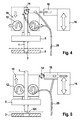
- the erosion voltage can now be applied between the workpiece 3 and the clamping device 14. This step of the erosion process is shown in FIG.
- the feed rollers 12 are now moved apart, as shown in FIG. 4, so that the erosion wire 1 is held only by the clamping device 14.
- a suitable erosion voltage is now applied between the clamping device 14 and the workpiece 3, so that a sparkover occurs between the erosion wire tip 101 and the workpiece 3, which finally removes material from the workpiece 3.
- the size of the erosion gap ie the distance between the erosion wire syringe 101 and the workpiece 3, changes continuously due to the forming recess 7, so that the erosion wire 1 is constantly tracked got to.
- This feed is controlled by the feed device 16, which moves the clamping device 14 and thus the erosion wire 1 in the direction of the workpiece 1 via the holding arm 18.
- the feed device 16 consists essentially of a piezoelectric actuator which has a sufficient length and a sufficient stroke in order to carry out the entire eroding process.
- FIG. 5 shows the end of the erosion process after the recess 7 has been introduced into the workpiece 3.
- the feed rollers 12 move back into contact with the erosion wire 1 and clamp this new, while the clamping device 14 is released from the erosion wire 1 and removed by the support arm 18 from the coarse feed device 10.
- About the feed rollers 12 of the erosion wire 1 is withdrawn and the erosion process is completed.
- the workpiece 3 can be replaced or moved to a new position, so that a new recess can be made.
- FIG. 6 shows an illustration of the movement of the eroding wire 1 as it can be carried out by the feed device 16.
- the size of the erosion gap can be selectively periodically changed even within narrow limits in order to achieve a better surface quality of the recess 7.
- the erosion wire 1 is moved forward in small steps, indicated here by a distance x. This distance is for example in the range of 10 nm. Subsequently, the erosion wire 1 is retracted by the feed unit 16 a distance y, which is smaller than the distance x, for example 5 nm.
- FIGS. 7a, 7b and 7c show the use of an optical sensor 30, with the aid of which this moment of the erosion process can be better controlled.
- FIG. 7 a shows the start of the erosion process, in which a feed device 10 'lowers the tip of the erosion wire 1 onto the workpiece 3, so that the erosion process can be started.
- the feed device 10 ' is shown here only schematically, which may include both a coarse feed device and a feed device for fine driving.
- FIG. 7b shows the time at which the erosion wire 1, the workpiece 3 just penetrates and an optical signal from the optical sensor 30 is registered.
- FIG. 7c shows the end of the erosion process after the complete shape of the recess 7 has been produced by the erosion wire 1.
- the optical sensor 30 is also connected to the control unit 20, where the evaluation of the sensor signals takes place, which in turn serve as an input for the control of the erosion process. It can also be provided to design the optical sensor 30 and the control unit 20 such that a spectral analysis of the optical signals is made possible. This makes it possible to make statements about the composition of the material material and thus also about current operating parameters of the erosion process.
- the optical sensor 30 may also be provided to simultaneously or alternatively use the electromagnetic sensor 24 to absorb the electromagnetic radiation emanating from the erosion process.
- the use of both signals allows a very precise control of the erosion process, as it is particularly advantageous in the design of small recesses 7.
Landscapes
- Chemical & Material Sciences (AREA)
- Chemical Kinetics & Catalysis (AREA)
- Electrochemistry (AREA)
- Engineering & Computer Science (AREA)
- Mechanical Engineering (AREA)
- Electrical Discharge Machining, Electrochemical Machining, And Combined Machining (AREA)
Applications Claiming Priority (1)
| Application Number | Priority Date | Filing Date | Title |
|---|---|---|---|
| DE200410050049 DE102004050049A1 (de) | 2004-10-14 | 2004-10-14 | Verfahren und Vorrichtung zum Elektroerodieren von Werkstücken |
Publications (2)
| Publication Number | Publication Date |
|---|---|
| EP1647347A2 true EP1647347A2 (fr) | 2006-04-19 |
| EP1647347A3 EP1647347A3 (fr) | 2006-07-19 |
Family
ID=35784741
Family Applications (1)
| Application Number | Title | Priority Date | Filing Date |
|---|---|---|---|
| EP05109273A Withdrawn EP1647347A3 (fr) | 2004-10-14 | 2005-10-06 | Méthode et appareil pour usinage par décharge électrique de pièces de travail. |
Country Status (2)
| Country | Link |
|---|---|
| EP (1) | EP1647347A3 (fr) |
| DE (1) | DE102004050049A1 (fr) |
Cited By (1)
| Publication number | Priority date | Publication date | Assignee | Title |
|---|---|---|---|---|
| EP1935545A2 (fr) * | 2006-12-22 | 2008-06-25 | Robert Bosch Gmbh | Dispositif destiné à la fabrication électro-érosive de forages |
Families Citing this family (1)
| Publication number | Priority date | Publication date | Assignee | Title |
|---|---|---|---|---|
| DE102006031197B4 (de) | 2006-07-03 | 2012-09-27 | Visteon Global Technologies Inc. | Innerer Wärmeübertrager mit Akkumulator |
Citations (5)
| Publication number | Priority date | Publication date | Assignee | Title |
|---|---|---|---|---|
| US5159167A (en) * | 1985-03-29 | 1992-10-27 | Raycon Corporation | Structure for and method of electrical discharge machining |
| US5951883A (en) * | 1997-07-31 | 1999-09-14 | Ann Arbor Machine Company | Floating cover electrode guide system for electric discharge machining |
| US6211480B1 (en) * | 1997-02-04 | 2001-04-03 | Mitsubishi Denki Kabushiki Kaisha | EDM machine for fine hole and EDM method using such machine |
| DE10155607A1 (de) * | 2001-11-13 | 2003-05-15 | Bosch Gmbh Robert | Verfahren und Vorrichtung zum Elektroerosives Abtragen |
| US6700088B1 (en) * | 1999-06-04 | 2004-03-02 | Amchem Limited | Sealing apparatus |
-
2004
- 2004-10-14 DE DE200410050049 patent/DE102004050049A1/de not_active Withdrawn
-
2005
- 2005-10-06 EP EP05109273A patent/EP1647347A3/fr not_active Withdrawn
Patent Citations (5)
| Publication number | Priority date | Publication date | Assignee | Title |
|---|---|---|---|---|
| US5159167A (en) * | 1985-03-29 | 1992-10-27 | Raycon Corporation | Structure for and method of electrical discharge machining |
| US6211480B1 (en) * | 1997-02-04 | 2001-04-03 | Mitsubishi Denki Kabushiki Kaisha | EDM machine for fine hole and EDM method using such machine |
| US5951883A (en) * | 1997-07-31 | 1999-09-14 | Ann Arbor Machine Company | Floating cover electrode guide system for electric discharge machining |
| US6700088B1 (en) * | 1999-06-04 | 2004-03-02 | Amchem Limited | Sealing apparatus |
| DE10155607A1 (de) * | 2001-11-13 | 2003-05-15 | Bosch Gmbh Robert | Verfahren und Vorrichtung zum Elektroerosives Abtragen |
Cited By (2)
| Publication number | Priority date | Publication date | Assignee | Title |
|---|---|---|---|---|
| EP1935545A2 (fr) * | 2006-12-22 | 2008-06-25 | Robert Bosch Gmbh | Dispositif destiné à la fabrication électro-érosive de forages |
| EP1935545A3 (fr) * | 2006-12-22 | 2012-04-25 | Robert Bosch Gmbh | Dispositif destiné à la fabrication électro-érosive de forages |
Also Published As
| Publication number | Publication date |
|---|---|
| EP1647347A3 (fr) | 2006-07-19 |
| DE102004050049A1 (de) | 2006-04-27 |
Similar Documents
| Publication | Publication Date | Title |
|---|---|---|
| EP1840368B1 (fr) | Buse d'injection dotée de canaux d'injection et procédé d'introduction de canaux | |
| DE3041612C1 (de) | Vorrichtung zur Winkellage-Orientierung von Drahtfuehrungselementen an polar oder kartesisch gesteuerten funkenerosiven Konisch-Schneidanlagen | |
| DE10311659B4 (de) | Vorrichtung und Verfahren zur optimierten elektrohydraulischen Druckpulserzeugung | |
| EP1827746B1 (fr) | Procede pour usiner une piece | |
| DE2721804A1 (de) | Verfahren und vorrichtung zur elektroerosiven bearbeitung | |
| EP1733837A1 (fr) | Dispositif pour séparer une pièce plane en matériau fragile par laser | |
| DE3933448A1 (de) | Verfahren und vorrichtung zum bohren einer besonders geformten bohrung in ein werkstueck | |
| EP1446254B1 (fr) | Procede et dispositif d'usinage de materiaux par electro-erosion d'une piece | |
| DE2940477A1 (de) | Elektrische bearbeitungsvorrichtung | |
| DE3142606C2 (fr) | ||
| DE3037505C2 (fr) | ||
| DE19738785A1 (de) | Elektronische Schweißenergiequelle | |
| EP2686126B1 (fr) | Procédé et dispositif d'usinage électrochimique de pièces | |
| DE3129716A1 (de) | Automatische drahteinstell- oder -wiedereinstellverfahren und -vorrichtung in einer durchlaufdraht-elektroerosionsmaschine | |
| EP0372258A2 (fr) | Procédé et dispositif de réglage d'une largeur de balayage présélectionnée d'un balai rotatif cylindrique | |
| DE3108536A1 (de) | Verfahren und vorrichtung zum elektroerosiven drahtschneiden | |
| EP3603872B1 (fr) | Dispositif et procédé de traitement d'une pièce par rayonnement laser | |
| EP1647347A2 (fr) | Méthode et appareil pour usinage par décharge électrique de pièces de travail. | |
| EP1409186B1 (fr) | Dispositif d'erosion comprenant une tete d'erosion concue pour eliminer des elements de connexion metalliques | |
| EP2468442B1 (fr) | Procédé de fabrication de forages | |
| DE4013432C2 (de) | Funkenerosive Drahtschneidemaschine mit einer Vorschubeinrichtung zum Einfädeln der Drahtelektrode | |
| EP0972622B1 (fr) | Procédé pour ajuster la longueur de coupe dans un procédé de granulation /extrusion, et appareil d'extrusion pour la mise en oeuvre du procédé | |
| EP2839917B1 (fr) | Machine d'électro-érosion ayant un dispositif pour l'enfilage du fil-électrode | |
| DE2512331A1 (de) | Elektroerosionsverfahren zur bearbeitung von werkstuecken und vorrichtung zur ausfuehrung dieses verfahrens | |
| EP1882540A2 (fr) | Procédé et dispositif destinés au traitement électrochimique |
Legal Events
| Date | Code | Title | Description |
|---|---|---|---|
| PUAI | Public reference made under article 153(3) epc to a published international application that has entered the european phase |
Free format text: ORIGINAL CODE: 0009012 |
|
| AK | Designated contracting states |
Kind code of ref document: A2 Designated state(s): AT BE BG CH CY CZ DE DK EE ES FI FR GB GR HU IE IS IT LI LT LU LV MC NL PL PT RO SE SI SK TR |
|
| AX | Request for extension of the european patent |
Extension state: AL BA HR MK YU |
|
| PUAL | Search report despatched |
Free format text: ORIGINAL CODE: 0009013 |
|
| AK | Designated contracting states |
Kind code of ref document: A3 Designated state(s): AT BE BG CH CY CZ DE DK EE ES FI FR GB GR HU IE IS IT LI LT LU LV MC NL PL PT RO SE SI SK TR |
|
| AX | Request for extension of the european patent |
Extension state: AL BA HR MK YU |
|
| 17P | Request for examination filed |
Effective date: 20070119 |
|
| AKX | Designation fees paid |
Designated state(s): CH DE FR IT LI |
|
| 17Q | First examination report despatched |
Effective date: 20070427 |
|
| STAA | Information on the status of an ep patent application or granted ep patent |
Free format text: STATUS: THE APPLICATION IS DEEMED TO BE WITHDRAWN |
|
| 18D | Application deemed to be withdrawn |
Effective date: 20090929 |