EP1646817B1 - Drive mechanisms for valve actuators - Google Patents
Drive mechanisms for valve actuators Download PDFInfo
- Publication number
- EP1646817B1 EP1646817B1 EP04743397A EP04743397A EP1646817B1 EP 1646817 B1 EP1646817 B1 EP 1646817B1 EP 04743397 A EP04743397 A EP 04743397A EP 04743397 A EP04743397 A EP 04743397A EP 1646817 B1 EP1646817 B1 EP 1646817B1
- Authority
- EP
- European Patent Office
- Prior art keywords
- actuator
- drive
- clutch
- intermediate shaft
- valve actuator
- Prior art date
- Legal status (The legal status is an assumption and is not a legal conclusion. Google has not performed a legal analysis and makes no representation as to the accuracy of the status listed.)
- Expired - Lifetime
Links
- 230000007246 mechanism Effects 0.000 title claims abstract description 45
- 230000008859 change Effects 0.000 claims abstract description 7
- 230000008901 benefit Effects 0.000 claims description 9
- 230000009467 reduction Effects 0.000 claims description 9
- 230000003068 static effect Effects 0.000 claims description 8
- 238000000465 moulding Methods 0.000 claims description 3
- 239000004033 plastic Substances 0.000 claims description 3
- 229920003023 plastic Polymers 0.000 claims description 3
- 230000003467 diminishing effect Effects 0.000 claims description 2
- 241000282472 Canis lupus familiaris Species 0.000 description 6
- 238000005516 engineering process Methods 0.000 description 6
- 239000012530 fluid Substances 0.000 description 6
- 230000009471 action Effects 0.000 description 4
- 230000006872 improvement Effects 0.000 description 4
- 238000010276 construction Methods 0.000 description 3
- 238000000034 method Methods 0.000 description 3
- 238000010586 diagram Methods 0.000 description 2
- 239000007788 liquid Substances 0.000 description 2
- 238000003754 machining Methods 0.000 description 2
- 239000000463 material Substances 0.000 description 2
- 206010037660 Pyrexia Diseases 0.000 description 1
- 230000000712 assembly Effects 0.000 description 1
- 238000000429 assembly Methods 0.000 description 1
- 238000005352 clarification Methods 0.000 description 1
- 239000007789 gas Substances 0.000 description 1
- 229910001385 heavy metal Inorganic materials 0.000 description 1
- 238000009434 installation Methods 0.000 description 1
- 239000010687 lubricating oil Substances 0.000 description 1
- 238000004519 manufacturing process Methods 0.000 description 1
- 229910052751 metal Inorganic materials 0.000 description 1
- 239000002184 metal Substances 0.000 description 1
- 239000002991 molded plastic Substances 0.000 description 1
- 230000002093 peripheral effect Effects 0.000 description 1
- 239000002990 reinforced plastic Substances 0.000 description 1
- 239000007787 solid Substances 0.000 description 1
- 239000000725 suspension Substances 0.000 description 1
- 238000007514 turning Methods 0.000 description 1
- 238000011144 upstream manufacturing Methods 0.000 description 1
Images



Classifications
-
- F—MECHANICAL ENGINEERING; LIGHTING; HEATING; WEAPONS; BLASTING
- F16—ENGINEERING ELEMENTS AND UNITS; GENERAL MEASURES FOR PRODUCING AND MAINTAINING EFFECTIVE FUNCTIONING OF MACHINES OR INSTALLATIONS; THERMAL INSULATION IN GENERAL
- F16D—COUPLINGS FOR TRANSMITTING ROTATION; CLUTCHES; BRAKES
- F16D11/00—Clutches in which the members have interengaging parts
- F16D11/08—Clutches in which the members have interengaging parts actuated by moving a non-rotating part axially
- F16D11/10—Clutches in which the members have interengaging parts actuated by moving a non-rotating part axially with clutching members movable only axially
-
- F—MECHANICAL ENGINEERING; LIGHTING; HEATING; WEAPONS; BLASTING
- F16—ENGINEERING ELEMENTS AND UNITS; GENERAL MEASURES FOR PRODUCING AND MAINTAINING EFFECTIVE FUNCTIONING OF MACHINES OR INSTALLATIONS; THERMAL INSULATION IN GENERAL
- F16K—VALVES; TAPS; COCKS; ACTUATING-FLOATS; DEVICES FOR VENTING OR AERATING
- F16K31/00—Actuating devices; Operating means; Releasing devices
- F16K31/02—Actuating devices; Operating means; Releasing devices electric; magnetic
- F16K31/04—Actuating devices; Operating means; Releasing devices electric; magnetic using a motor
- F16K31/05—Actuating devices; Operating means; Releasing devices electric; magnetic using a motor specially adapted for operating hand-operated valves or for combined motor and hand operation
- F16K31/055—Actuating devices; Operating means; Releasing devices electric; magnetic using a motor specially adapted for operating hand-operated valves or for combined motor and hand operation for rotating valves
Definitions
- the present invention relates to drive mechanisms for transmitting a drive from a driving rotating member to a driven rotating member and particularly, but not exclusively, to mechanisms used for operating valves, sluices, penstocks and the like for controlling the flow of fluids.
- fluids In this context covers liquids, gases and vapours, and multi-state fluids such as liquids containing solids in suspension.
- the driving member is an electric motor and the reduction drive to the driven shaft is in the form of a worm and worm wheel, the latter being keyed or otherwise fixed to the actuator output shaft or "column" which operates the moving element of the valve.
- valve actuation technology it is common practice to arrange the drive system such that only forces and torsion generated by the driving rotating member or members of the actuator can be transmitted through the gearing to the driven rotating member; this is to eliminate the problem that can arise when no power is being provided to the driving member and the unbalanced forces generated by the pressurised fluid within the valve are sufficient, when acting on the valve moving member, to "back drive” the actuator gear train resulting in the valve moving member being displaced from its seating or from its last position in the fluid path determined by the last operation of the valve actuator.
- One common method used to eliminate- the back driving possibility in an actuator gear train is to use a substantial reduction ratio on the worm/worm wheel mesh, the resulting low value of the worm lead angle combined with the normal friction coefficient at the meshing surfaces causing the drive to lock when torque is applied to the worm wheel side of the drive.
- a two position clutch and a hand operated wheel are provided. These members are normally provided on the actuator output shaft which carries the worm wheel.
- the clutch is operated by a manual lever.
- the lever is spring biased to a parked position and the normal state of the drive mechanism is to be clutched into the power driving mode. Operating the lever over its full arc of travel uncouples the clutch moving member from the power driving position and moves it into the manual driving position. Simultaneously, the lever operates a latching mechanism which ensures that the clutch remains in the manual driving mode when the lever is released and returns to its parked position.
- the latching mechanism is so designed that it will hold the actuator in the hand drive state until the power drive is energised again. Rotation of the de-clutched member of the drive train then automatically releases the latch mechanism and allows the clutch moving member to return, under spring load, to its power driving position.
- This automatic reversion to the power driving mode is a common feature of Valve Operation Technology and has come about to avoid the need to send operating staff out, sometimes long distances, to un-manned sites to attend to valve actuators which have been inadvertently left in manual drive mode after a service visit etc.
- the output shaft mounted hand wheel as well as the lever used to uncouple the clutch from the power mode and move into hand drive mode need to be of substantial, all metal construction, adding considerably to the size and weight of the actuator.
- the present invention sets out to eliminate the locked in torque from the power driving side of the clutch assembly and to further reduce the operating torque required at the hand wheel so that, in addition to requiring less manual effort to operate the lever and hand wheel, the components that make up the clutch, lever and hand wheel assemblies can be reduced in size and, if required, can be manufactured from mouldings made of plastic or reinforced plastic materials.
- a typical existing method, used in Valve Actuation Technology to hold the actuator drive in hand mode after operating the lever, but automatically to change to power drive as soon as the drive motor starts to rotate, is achieved by providing a propping mechanism between one face of the worm wheel and the clutch moving member. This mechanism holds the clutch moving member in its hand drive position and compresses the spring means which urges the clutch moving member into its power driving position.
- the essential feature of the prop mechanism is a pivoted latch member which forms the end of the prop adjacent to the worm wheel.
- the latch member is provided with a light centering spring which holds the member at right angles to the worm wheel surface when the hand operation mode has been selected.
- the friction between the wheel moving surface and the foot of the latch member overcomes the light centering spring means and causes the latch member to rotate approximately 90 degrees to a trailing, parallel position on the worm wheel surface.
- the resulting movement of the latch member pivot, in an axial direction relative to the worm wheel shaft is sufficient to allow the clutch moving member to engage power drive.
- a motorised valve actuator having an alternative manual drive, the manual drive comprising a hand wheel and a clutch mechanism and lever to change from motor power drive to hand drive mode, the actuator further having an intermediate shaft between the motor and output shaft, the hand wheel being operatively linked to the intermediate shaft to drive the intermediate shaft, the intermediate shaft being positioned between the motor and the gear mesh whereby when the lever is operated to bring the actuator into hand drive mode the clutch mechanism operates substantially freely, the output shaft torque generated by the previous motor powered run and locked into the output shaft by the non-back driving gear mesh not being locked into the clutch mechanism characterised in that the drive from the motor to the output shaft of the actuator is via a gear mesh which is incapable of being back driven, and the clutch mechanism comprises a moving clutch member and a co-operating clutch operator having co-operating conical surfaces.
- the non-back-driveable gear mesh comprises a worm and worm wheel assembly and preferably the clutch mechanism is associated with/mounted on the intermediate shaft.
- the actuator further has a gear reduction drive associated with the intermediate shaft to yet further increase the ease with which the output shaft of the actuator may be manually driven.
- At least one of and preferably each of the hand wheel, lever and certain clutch components may be formed of moulded plastics materials.
- the actuator of the present invention may thus be constructed more cost effectively as well as being more compact, lighter and much easier to use than the existing actuators.
- Further improvements to the actuator include forming the moving clutch member and co-operating clutch operator with cooperating conical surfaces whereby the clutch may be moved from motor drive engagement to hand drive engagement yet more easily.
- the sliding conical surfaces on the moving clutch member and the clutch operator are preferably configured with the clutch operator's conical surface wrapping at least partially round the moving clutch member's conical surface so that there is substantial area contact at the start of a de-clutching operation, the area rapidly diminishing towards a line contact as the clutch moving member rises to the hand drive position.
- the clutch operator's conical surface wraps up to 180 degrees round the moving clutch member's conical surface.
- the actuator has a rotating cam member that is driven by the lever and which cooperates with the clutch operator in order to vary the mechanical advantage between the lever movement and the moving clutch member via the sliding conical surfaces.
- This cam member suitably provides a higher mechanical advantage at the start of a declutching operation in order to overcome the higher static friction coefficients and provides a lower mechanical advantage ratio or ratios for the remaining travel of the lever when operating against the relatively lower dynamic friction coefficients, the lower mechanical advantage ratio or ratios producing a smaller total angular travel of the lever.
- the lever's rotation axis is positioned parallel and adjacent to the hand wheel's rotation axis and suitably the lever has a curved shape and is configured to swing underneath the hand wheel circular periphery and partly surround the hand wheel boss, both these features being used to reduce the space required to accommodate the actuator when installed on the valve.
- the actuator further comprises a latch member to latch the clutch in engagement for hand drive and suitably the latch member is provided with teeth, which teeth engage with teeth of a gear wheel of the drive train of the actuator to latch the actuator in its hand drive state, thereby providing a positive engagement when in hand drive mode and a positively driven dis-engagement operation when returning to power drive mode.
- the gear wheel is driven by the motor and associated with/ mounted on the intermediate shaft, the gear wheel, by operation of the clutch, being selectively engageable with the intermediate shaft to drive the intermediate shaft.
- the latch member is pivoted and has adjacent thereto a flat spring means with which the latch member co-operates, the flat spring means serving to bias the latch member to pivot toward its hand drive engaged latch position.
- the latch member is provided with a faceted boss and which boss co-operates with the flat spring means so that in a "trailing" disengaged position the latch member is positively held out of contact with the member with which it otherwise engages in its hand drive engaging latch position.
- the latch member co-operates with the flat spring in order to provide three parked positions for the latch member, these being the two “trailing" positions depending on the direction of rotation of the gear wheel 29 and the central engaged position when the mechanism is latched in hand drive mode.
- the faceted boss is preferably substantially rectangular/ substantially square.
- the latch member is pivotal and latch mechanism of the actuator further comprises at least one static post means to deflect the latch member to pivot positively from a disengaged "trailing" position substantially into the latched position and preferably there are a pair of spaced apart such static post means between which the latch member is moved as the lever is operated in order to move the latch member from either of two trailing positions.
- the clutch has a moving clutch member
- the intermediate shaft suitably has pinion gear teeth to co-operatively engage with a co-operating gear on a shaft for driving the worm/ worm wheel
- the intermediate shaft suitably further has splines that cooperate with the moving clutch member whereby the moving clutch member is slidable longitudinally of the intermediate shaft but rotates therewith
- the pinion gear teeth are particularly preferably extended longitudinally of the intermediate shaft whereby the splines are formed of these longitudinal extensions of the pinion gear teeth.
- the longitudinal extensions of the pinion gear teeth on the intermediate shaft are cut back to a reduced diameter.
- the reduced diameter of the extensions provides a location on the intermediate shaft about which the gear wheel driven by the drive motor may freely rotate and also provides an abutment step serving as an axial location for the motor driven gear wheel, or for an interposing thrust washer.
- a motorised valve actuator of the type having an alternative manual drive, the manual drive comprising a hand wheel and a clutch and lever to change from motor power drive to hand drive mode, wherein the actuator comprises a latch member to latch the clutch in engagement for hand drive or motor drive, the latch member being provided with teeth which engage with teeth of a gear wheel of the drive train of the actuator in order to provide a positive engagement when in hand drive mode and a positively driven dis-engagement operation when returning to power drive mode.
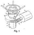
- the electric motor 1 drives the worm wheel 2 by means of the worm 3.
- the worm wheel 2 is free to rotate on the actuator output shaft 4.
- a moving clutch member 5 is free to move axially on the output shaft 4 but is located radially on the shaft by the key or splines 6.
- a hand wheel 7 is also mounted on the output shaft 4 being free to rotate independently of the shaft.
- the clutch moving member 5 can be moved into engagement with either the worm wheel 2 by means of the dogs 8 and slots 9 or into engagement with the hand wheel 7 by means of the dogs 10 and slots 11.
- the lead angle on the worm 3, meshing with the worm wheel teeth, is normally sufficiently small to prevent back driving of the mechanism when torque is applied to the shaft 4.
- the torque locked into the output shaft 4 is transmitted to the locking mesh of the worm wheel and worm via the dogs and slots 8 and 9. This results in a significant axial force being required to disengage the clutch from the power drive mode.
- the hand wheel 7 is then able to operate the valve via the actuator output shaft 4; the hand wheel torque required being equivalent to that supplied by the power drive.
- the hand wheel has to be provided with extended spokes 12 to enable the operator to generate the significant manual torque required to operate the valve manually.
- Figure 2 shows a known partial solution to the problem of reducing the hand wheel torque by placing the hand wheel drive with the associated clutch mechanism and the worm wheel on an intermediate shaft 13 carrying pinion gear 14 which meshes with a gear wheel 15 mounted on the actuator output shaft 16.
- Figure 2 also shows one form of the known mechanism used for automatically re-engaging the power drive when the motor 1 is energised.
- a latch member 22 On the lower end of the shaft 17 is pivoted a latch member 22, shown in its trailing attitude with the clutch still engaging the worm wheel.
- This latch member is urged into a vertical position from either a left or right hand trailing position (depending on the rotation direction of the worm wheel) by means of a self centering wire torsion spring (not illustrated) surrounding the pivot 23.
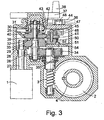
- Figures 3 and 4 are semi-diagrammatic sectional view through the principal shaft centres of the drive and Figure 4 showing an isometric, vertically exploded view of some of the components making up the clutch mechanism and which need further clarification.
- the intermediate shaft carries the moving clutch member 25 and is provided with an integral pinion 26.
- the motor shaft 27 has an integral pinion 28 which drives the gear wheel 29 also located -on the intermediate shaft 24 but free to rotate independently of the shaft 24.
- the moving clutch member 25 is provided with splines 30 which cooperate with splines 31 allowing the moving clutch member to slide freely on the shaft 24 but to be fixed rotationally relative to the shaft.
- the moving clutch member 25 is in its descended power driving position with a protruding peg 32 cooperating with a circular hole or arc shaped blind slot 33 formed in the gear wheel 29.
- the motor 1 is able to drive the intermediate shaft 24 via the meshing pinion 28 and gear wheel 29 the torque being transmitted to the shaft 24 via the peg 32 cooperating with the hole or blind slot 33 and the splines 30 on the moving clutch member 25 meshing with the extended length splines 31 on the shaft 24.
- the intermediate shaft 24 is permanently, drivably coupled to the actuator output shaft 4 via the pinion 26 meshing with the gear wheel 34 which, in turn, is keyed to the shaft 35 on which is machined the worm 3.
- the worm meshes with the worm wheel 2, the latter being keyed or otherwise permanently attached to the actuator output shaft 4.
- the clutch assembly and the associated operating lever 36 can be made of light construction and, in particular, can make use of plastics mouldings in place of the relatively heavy metal components in the designs depicted in Figures 1 and 2.
- the additional gear reduction drive via the intermediate shaft further enables the hand wheel assembly to be of lighter construction than that required in the designs shown in Figure 1, enabling replacement of the extended spokes 12 and the large hand wheel 7 with the modest size, moulded wheel 37 and turning handle 38.
- the moving clutch member 25 is provided with a conical outer surface 39 which cooperates with an extended inner conical surface 40 of the clutch operator 41.
- the cone half angle is approximately 45 degrees as shown in Figure 3: the surrounding clutch operator conical inner surface 40 is cut away as shown in Figure 4, the "wrapping" angle surrounding the moving clutch member 25 being equal to, or less than 180 degrees in order to allow the clutch operator 41 to travel in a horizontal direction to the right as viewed in Figure 3.
- the clutch operator is constrained by the surrounding housing to move only in a single horizontal plane, the travel to the right being converted into an equivalent vertical lift of the moving clutch member 25 by the sliding action of the extended conical surface 40 on the surface 39, the vertical movement disengaging the power drive and engaging the set of radial face teeth 42 on the moving clutch member 25 with a cooperating set of teeth 43 on the hand wheel shaft assembly.
- the movement of the lever 36 (clockwise as viewed in Figure 7) from its parked position to its operating position 44 causes the clutch operator 41 to travel in its constrained horizontal direction by the action of the profiled slot 45 in the rotating cam member 46 on the integral post 47 moulded on to the clutch operator 41.
- the cam member 46 is keyed, or otherwise attached, to the shaft 48 of the lever 36.
- the profited slot 45 is so shaped that, from its parked position, a significant portion of the movement of lever 36 is used to provide a small initial deflection of the post 47 in order to increase the mechanical advantage of the lever/cam profile and so overcome the higher static friction force between the operating conical surfaces 39 and 40 at the start of a dedutching operation.
- the friction coefficient between the lubricated conical surfaces will decrease to a value, typically about half the static value coefficient enabling a lower mechanical advantage to be used for the remainder of the lever 36 travel.
- the male cone surface 39 and its cooperating half circular surface 40 are only in full surface contact at the start of a power declutching operation. This allows the maximum available contacting surface area to be used with consequent minimum surface contact pressure when overcoming the force generated by the higher static friction.
- the clutch operator 41 starts to move and the moving clutch member rises, the surface area in contact rapidly starts to diminish because horizontal (as drawn in Figure 3) sections taken through the contacting cones will show, in theory, circles of different diameters in line contact.
- the surface deflection produced by the operating forces will provide a narrow width contact area in place of the theoretical line contact of the two moving conical surfaces.
- the lever 36 is spring biased so that, on release, it returns to the parked position parity shielded by the overhanging hand wheel 37. Referring to Figure 4, this is achieved, typically, by means of a coil tension spring 49, one end being anchored to the actuator housing and the other end being attached to the cam member 46 at a position such that the spring tension force produces the return travel torque on the cam member 46 and thence to the lever 36 via the lever shaft 48.
- the post 47 is provided with a hole in its base into which is inserted a small shaft 50 acting as a pivot for the new design latch member 51: this last component operates in the same manner as the known component 22 in Figure 2 but provides significant improvements.
- the flat spring ends are located by slots, or other means, in the clutch operator 41 and therefore stay in the same position relative to the pivot and shaft 50 during a de-clutching operation.
- the latch member 51 is forced to rotate through nearly, 90 degrees by being withdrawn between the two posts 54 located in the actuator housing.
- the final angular travel to the latched position is achieved by the flat spring 52 being first deflected by the corner of the rotating square boss 53, shown chain dotted in Figure 5, and then returning to it's initial flat position forcing the latch member the final few degrees into the position shown in Figure 6.
- the horizontal travel has to be a little longer than the distance between latched and unlatched positions. This is to allow the teeth 55 on the latch member to pass over the teeth on the gear wheel 29 before engagement
- the return to power drive mode is initiated by the rotation of the gear wheel 29 driven by the motor 1.
- the latch member 51 now rotates; being in mesh with the engaged teeth of the gear wheel, and so allowing the clutch operator 41 to return towards the power drive mode position.
- the final few degrees of rotation cause the latch member 51 to "spring" into the Figure 5 position with all the latching teeth 55 held clear of the gear wheel teeth.
- the shaft 24 shown in Figure 3 carries an integral meshing pinion 26 having teeth of standard involute form and an upper, as drawn, male spline section 31 which cooperates with the splined bore of the moving clutch member 25.
- the enlarged central diameter on which the shaft 24 can rotate relative to the gear wheel 29 (in hand drive) prevents the use of a through broaching operation when forming the teeth.
- the intermediate shaft 56 carries only one set of gear teeth which are extended to form the driving pinion at the lower end of the- shaft as drawn.
- An abutment step 58 is formed on the shaft by machining down the teeth, typically to a diameter 59 approximately equivalent to the involute gear circular pitch diameter; that is machining off the gear teeth addendum.
- the bore of the moving clutch member 25 can now be machined out to form a cooperating splined hole to slide on the cut down teeth on the shaft 56 as shown in the upper local transverse section.
- the gear wheel 29 can rotate over the cut down teeth as shown in the middle local section in Figure 8.
- a thrust washer 60 may be interposed between the abutment step 58 and the moving clutch member 25.
- the shaft 56 only rotates at relatively slow speed within the gear wheel 29 and without transmitting any torque to the wheel when the actuator is in hand drive so there will be no significant wear due to the interrupted circular contacts between the gear wheel and the shaft.
Landscapes
- Engineering & Computer Science (AREA)
- General Engineering & Computer Science (AREA)
- Mechanical Engineering (AREA)
- Gear Transmission (AREA)
- Mechanically-Actuated Valves (AREA)
- Mechanical Operated Clutches (AREA)
- Electrically Driven Valve-Operating Means (AREA)
- Fluid-Driven Valves (AREA)
- Actuator (AREA)
- Valve-Gear Or Valve Arrangements (AREA)
- Valve Device For Special Equipments (AREA)
Applications Claiming Priority (2)
| Application Number | Priority Date | Filing Date | Title |
|---|---|---|---|
| GB0316735A GB2404717B (en) | 2003-07-17 | 2003-07-17 | Drive mechanisms for valve actuators |
| PCT/GB2004/003056 WO2005010416A1 (en) | 2003-07-17 | 2004-07-14 | Drive mechanisms for valve actuators |
Publications (2)
| Publication Number | Publication Date |
|---|---|
| EP1646817A1 EP1646817A1 (en) | 2006-04-19 |
| EP1646817B1 true EP1646817B1 (en) | 2007-10-24 |
Family
ID=27763990
Family Applications (1)
| Application Number | Title | Priority Date | Filing Date |
|---|---|---|---|
| EP04743397A Expired - Lifetime EP1646817B1 (en) | 2003-07-17 | 2004-07-14 | Drive mechanisms for valve actuators |
Country Status (11)
| Country | Link |
|---|---|
| US (1) | US7055795B2 (enExample) |
| EP (1) | EP1646817B1 (enExample) |
| JP (1) | JP4531757B2 (enExample) |
| CN (2) | CN2718356Y (enExample) |
| AT (1) | ATE376642T1 (enExample) |
| DE (1) | DE602004009688T2 (enExample) |
| ES (1) | ES2295885T3 (enExample) |
| GB (1) | GB2404717B (enExample) |
| NO (1) | NO330840B1 (enExample) |
| RU (2) | RU41109U1 (enExample) |
| WO (1) | WO2005010416A1 (enExample) |
Cited By (1)
| Publication number | Priority date | Publication date | Assignee | Title |
|---|---|---|---|---|
| US12523264B2 (en) | 2022-03-15 | 2026-01-13 | Hyundai Motor Company; | Clutch for preventing backdrive |
Families Citing this family (52)
| Publication number | Priority date | Publication date | Assignee | Title |
|---|---|---|---|---|
| GB2404717B (en) * | 2003-07-17 | 2005-12-21 | Rotork Controls | Drive mechanisms for valve actuators |
| CH708995B1 (de) * | 2004-03-19 | 2015-06-30 | Belimo Holding Ag | Reduktionsgetriebe eines elektrisch betriebenen Stellglieds. |
| US7182314B2 (en) * | 2005-02-28 | 2007-02-27 | Mastergear Usa | Apparatus for actuating a valve |
| CN100353108C (zh) * | 2005-06-20 | 2007-12-05 | 鞍山德隆自动化工程有限公司 | 新型阀门电动装置 |
| US7654504B2 (en) * | 2006-02-09 | 2010-02-02 | Parker & Harper Companies, Inc. | Power actuated valve |
| BRPI0621387B1 (pt) * | 2006-03-07 | 2018-11-27 | Flowserve Management Company | método para acionar codificador de posição de atuador de válvula e sistema de atuador de válvula |
| RU2319055C1 (ru) * | 2006-07-03 | 2008-03-10 | Петр Тихонович Харитонов | Клапан электромагнитный с ручным дублером |
| ES2331429T3 (es) * | 2006-08-02 | 2010-01-04 | Orkli, S. Coop. | Actuador lineal de motor para una valvula de tres vias. |
| RU2332607C1 (ru) * | 2007-05-17 | 2008-08-27 | Прилукова Галина Ивановна | Привод с комбинированным управлением от электродвигателя и вручную |
| US7913972B2 (en) * | 2008-02-04 | 2011-03-29 | Schneider Electric Buildings, Llc | Two position actuator with mechanical hold |
| KR100957150B1 (ko) * | 2008-03-12 | 2010-05-11 | 현대자동차주식회사 | 클러치 액츄에이터 |
| US8587170B2 (en) | 2008-05-21 | 2013-11-19 | Siemens Industry, Inc. | Actuator arrangement with worm gear and rotational output having an encoder |
| US8544817B2 (en) * | 2008-06-11 | 2013-10-01 | Regal Beloit America, Inc. | Manual valve operator with override clutch apparatus |
| ES2402389T5 (es) * | 2009-06-16 | 2017-03-10 | Georg Fischer Rohrleitungssysteme Ag | Dispositivo de accionamiento para el accionamiento de válvulas |
| US8157242B2 (en) * | 2009-12-11 | 2012-04-17 | Schneider Electric Buildings, Llc | Valve actuator with lock mechanism |
| KR101165976B1 (ko) * | 2010-08-04 | 2012-07-18 | 주식회사알피엠텍 | 전동식 밸브 작동기의 클러치 장치 |
| CN101975306B (zh) * | 2010-10-28 | 2012-07-04 | 金显静 | 可变速手动阀门蜗轮箱驱动装置 |
| KR20120054410A (ko) * | 2010-11-19 | 2012-05-30 | 주식회사 만도 | 터보차저의 전기식 웨이스트 게이트 엑츄에이터 |
| US8728248B2 (en) * | 2011-09-07 | 2014-05-20 | General Electric Company | Adjustable filter system for a dishwashing appliance |
| JP5912636B2 (ja) * | 2012-02-17 | 2016-04-27 | 西部電機株式会社 | バルブコントロールと電動ゲート及び電動弁 |
| US10119721B2 (en) | 2012-06-14 | 2018-11-06 | Honeywell International Inc. | Standoff for use with an insulated HVAC duct |
| US10302207B2 (en) | 2012-06-14 | 2019-05-28 | Honeywell International Inc. | Spring loaded HVAC damper |
| US9032993B2 (en) * | 2012-06-14 | 2015-05-19 | Honeywell International Inc. | Handle mechanism for an HVAC damper actuator |
| CN103671739A (zh) * | 2012-09-03 | 2014-03-26 | 上海浦东汉威阀门有限公司 | 一种摆齿减速器 |
| US9114798B1 (en) | 2012-12-12 | 2015-08-25 | Hydro-Gear Limited Partnership | Electric actuator for drive apparatus |
| CN103244737B (zh) * | 2013-05-22 | 2015-01-14 | 中国能建集团装备有限公司南京技术中心 | 用于阀门驱动装置的手动与电动切换机构 |
| US9618136B2 (en) | 2013-09-16 | 2017-04-11 | Fisher Controls International Llc | Rotary valve position indicator |
| US10060550B2 (en) * | 2013-11-21 | 2018-08-28 | Aktiebolaget Skf | Valve operator assembly with friction means and pre-stressing element |
| US9732980B2 (en) | 2013-12-18 | 2017-08-15 | Honeywell International Inc. | HVAC actuator with range adjustment |
| US10941960B2 (en) | 2013-12-18 | 2021-03-09 | Ademco Inc. | HVAC actuator with position indicator |
| CN104089070B (zh) * | 2014-07-24 | 2016-08-17 | 苏州博睿测控设备有限公司 | 一种电动执行器手动机构 |
| CN104633255B (zh) * | 2015-02-10 | 2017-07-11 | 无锡智能自控工程股份有限公司 | 随动式长行程手轮机构 |
| CN104696579A (zh) * | 2015-03-18 | 2015-06-10 | 安策阀门(太仓)有限公司 | 一种阀门转动驱动装置 |
| CN104776249A (zh) * | 2015-04-27 | 2015-07-15 | 陕西富锐泳池环境科技有限公司 | 一种五通球阀 |
| KR102408251B1 (ko) * | 2015-10-01 | 2022-06-13 | 엘지이노텍 주식회사 | 파킹 브레이크 액츄에이터 |
| EP3150889A1 (en) * | 2015-10-01 | 2017-04-05 | IMI Hydronic Engineering International SA | An actuator for controlling a valve |
| CN105840901B (zh) * | 2016-04-21 | 2018-05-11 | 重庆云陆阀门制造有限公司 | 双重定位弹性硬密封球阀 |
| JP6502443B2 (ja) * | 2017-09-01 | 2019-04-17 | 株式会社エフ・シー・シー | 動力伝達装置 |
| RU2701982C1 (ru) * | 2018-10-05 | 2019-10-02 | федеральное государственное бюджетное образовательное учреждение высшего образования "Ижевский государственный технический университет имени М.Т. Калашникова" | Двухскоростной ручной привод запорной арматуры |
| RU2730750C1 (ru) * | 2019-11-01 | 2020-08-25 | Общество С Ограниченной Ответственностью Научно-Производственное Предприятие "Томская Электронная Компания" | Электропривод с ручным дублером |
| EP3822528A1 (en) * | 2019-11-13 | 2021-05-19 | Akron Brass Company | Electrically controlled valve actuator |
| US11614180B2 (en) * | 2019-12-27 | 2023-03-28 | Takatori Seisakusho Co., Ltd. | Valve actuator |
| CN111425650A (zh) * | 2020-03-03 | 2020-07-17 | 中国石化销售股份有限公司华南分公司 | 盘式电机驱动涡轮蜗杆传动角行程式快速切断执行机构 |
| US11738635B2 (en) * | 2020-03-23 | 2023-08-29 | Inteva Products, Llc | Dual output actuator |
| WO2021228780A1 (en) | 2020-05-11 | 2021-11-18 | Rotiny Aps | Actuator for fluid flow controllers |
| CN113623451B (zh) * | 2021-07-06 | 2024-09-24 | 西南石油大学 | 一种高压闸阀手自一体执行机构 |
| KR102625650B1 (ko) * | 2021-08-30 | 2024-01-17 | 엘지전자 주식회사 | 밸브 액튜에이터 |
| KR102621332B1 (ko) * | 2021-09-29 | 2024-01-08 | 엘지전자 주식회사 | 밸브 액츄에이터 |
| DE102021134550A1 (de) * | 2021-12-23 | 2023-06-29 | Auma Riester Gmbh & Co. Kg | Stellantrieb |
| CN114877119A (zh) * | 2022-04-27 | 2022-08-09 | 天地(常州)自动化股份有限公司 | 提高安全性能的电动执行器及其手电动切换方法 |
| CN115183042B (zh) * | 2022-09-13 | 2022-11-25 | 常州华立阀门控制设备有限公司 | 多回转电动阀门执行器 |
| CN116123345B (zh) * | 2023-02-09 | 2026-04-21 | 百阀邦尼(北京)科技有限公司 | 阀门致动器 |
Family Cites Families (10)
| Publication number | Priority date | Publication date | Assignee | Title |
|---|---|---|---|---|
| GB706285A (en) * | 1951-07-30 | 1954-03-24 | Philadelphia Gear Works Inc | Improvement in valve actuating mechanism |
| US4429591A (en) * | 1979-03-13 | 1984-02-07 | Eim Company, Inc. | Drive shifting apparatus for valve control and the like |
| ATE3665T1 (de) * | 1979-09-28 | 1983-06-15 | Rotork Limited | Betaetigungsvorrichtung mit wahlweisem motoroder handantrieb. |
| US4398562A (en) * | 1981-07-06 | 1983-08-16 | Richdel, Inc. | Motorized diverter valve |
| GB2120349B (en) * | 1982-05-12 | 1985-08-29 | Rotork Controls | Valve actuators having alternative manual and power inputs |
| US4453624A (en) * | 1982-06-01 | 1984-06-12 | The Singer Company | Handwheel clutch for sewing machines |
| US4474078A (en) * | 1982-06-21 | 1984-10-02 | Philadelphia Gear Corporation | Valve operator de-clutch mechanism |
| DE3521398C1 (de) * | 1985-06-14 | 1986-10-23 | Elektro-Mechanik Gmbh, 5963 Wenden | Vorrichtung zur Arretierung und Schaltung einer Kupplung |
| SU1352140A1 (ru) * | 1986-06-17 | 1987-11-15 | В.П.Заварзин и В.Т.Лемберг | Электрический привод |
| GB2404717B (en) * | 2003-07-17 | 2005-12-21 | Rotork Controls | Drive mechanisms for valve actuators |
-
2003
- 2003-07-17 GB GB0316735A patent/GB2404717B/en not_active Expired - Lifetime
- 2003-10-28 RU RU2003131459/22U patent/RU41109U1/ru active Protection Beyond IP Right Term
- 2003-10-29 CN CNU2003201024674U patent/CN2718356Y/zh not_active Expired - Lifetime
-
2004
- 2004-04-19 US US10/827,500 patent/US7055795B2/en not_active Expired - Lifetime
- 2004-07-14 RU RU2006104853/06A patent/RU2334152C2/ru active
- 2004-07-14 ES ES04743397T patent/ES2295885T3/es not_active Expired - Lifetime
- 2004-07-14 DE DE602004009688T patent/DE602004009688T2/de not_active Expired - Lifetime
- 2004-07-14 AT AT04743397T patent/ATE376642T1/de not_active IP Right Cessation
- 2004-07-14 JP JP2006519999A patent/JP4531757B2/ja not_active Expired - Lifetime
- 2004-07-14 CN CNB2004800156781A patent/CN100398892C/zh not_active Expired - Lifetime
- 2004-07-14 WO PCT/GB2004/003056 patent/WO2005010416A1/en not_active Ceased
- 2004-07-14 EP EP04743397A patent/EP1646817B1/en not_active Expired - Lifetime
-
2005
- 2005-12-13 NO NO20055906A patent/NO330840B1/no unknown
Cited By (1)
| Publication number | Priority date | Publication date | Assignee | Title |
|---|---|---|---|---|
| US12523264B2 (en) | 2022-03-15 | 2026-01-13 | Hyundai Motor Company; | Clutch for preventing backdrive |
Also Published As
| Publication number | Publication date |
|---|---|
| NO20055906L (no) | 2005-12-13 |
| JP4531757B2 (ja) | 2010-08-25 |
| RU2006104853A (ru) | 2006-06-10 |
| CN1802531A (zh) | 2006-07-12 |
| CN2718356Y (zh) | 2005-08-17 |
| NO330840B1 (no) | 2011-07-25 |
| US20050012064A1 (en) | 2005-01-20 |
| DE602004009688T2 (de) | 2008-08-28 |
| GB2404717C (en) | |
| DE602004009688D1 (de) | 2007-12-06 |
| RU41109U1 (ru) | 2004-10-10 |
| GB2404717B (en) | 2005-12-21 |
| JP2007516390A (ja) | 2007-06-21 |
| US7055795B2 (en) | 2006-06-06 |
| CN100398892C (zh) | 2008-07-02 |
| RU2334152C2 (ru) | 2008-09-20 |
| ATE376642T1 (de) | 2007-11-15 |
| GB2404717A (en) | 2005-02-09 |
| WO2005010416A1 (en) | 2005-02-03 |
| EP1646817A1 (en) | 2006-04-19 |
| ES2295885T3 (es) | 2008-04-16 |
| GB0316735D0 (en) | 2003-08-20 |
Similar Documents
| Publication | Publication Date | Title |
|---|---|---|
| US7055795B2 (en) | Drive mechanisms for valve actuators | |
| US4920811A (en) | Fail-safe release actuator mechanism | |
| US8215196B2 (en) | Tong gear shift system | |
| CA1317584C (en) | Valve actuator differential worm planetary gear drive | |
| US7987959B2 (en) | Actuator, range changeover device for automatic transmission, and parking device | |
| KR20240117063A (ko) | 모듈형 감속 기어 | |
| US10215267B2 (en) | Valve closing device and valve actuating assembly | |
| JPS6249504B2 (enExample) | ||
| RU2324858C2 (ru) | Устройство дистанционного управления для быстрого соединения и быстрого разъединения трубного фитинга с фланцевой трубой | |
| KR102244723B1 (ko) | 이중 재질 스템너트를 가지는 온도 보정용 밸브 개폐장치, 듀얼 감속비 감속기 및 듀얼 감속비 온도 보정용 밸브 개폐장치 | |
| US2954703A (en) | Fast-acting valve system | |
| US11920697B2 (en) | Failsafe module | |
| EP3356709A1 (en) | An actuator for controlling a valve | |
| CN107250638B (zh) | 具有双螺丝机构和可操作的轮的阀操作器组件 | |
| JP7528825B2 (ja) | 減速機構 | |
| KR19990021781U (ko) | 수문권양기의브레이크장치 | |
| JP7515472B2 (ja) | 逆転駆動装置を備えた車両用トランスミッションユニット及び該トランスミッションユニットを搭載した車両 | |
| RU2433326C1 (ru) | Двухскоростное приводное устройство | |
| GB2572735A (en) | Failsafe industrial actuator | |
| RU2797329C1 (ru) | Электропривод трубопроводной арматуры с ручным дублером | |
| RU2332607C1 (ru) | Привод с комбинированным управлением от электродвигателя и вручную | |
| GB2216625A (en) | Mechanical actuator mechanism | |
| JP4058694B2 (ja) | 減速比可変式動力舵取り装置 | |
| RU2218504C2 (ru) | Электропривод к задвижкам трубопроводов | |
| SU1147553A1 (ru) | Устройство дл сборки резьбовых соединений |
Legal Events
| Date | Code | Title | Description |
|---|---|---|---|
| PUAI | Public reference made under article 153(3) epc to a published international application that has entered the european phase |
Free format text: ORIGINAL CODE: 0009012 |
|
| 17P | Request for examination filed |
Effective date: 20051123 |
|
| AK | Designated contracting states |
Kind code of ref document: A1 Designated state(s): AT BE BG CH CY CZ DE DK EE ES FI FR GB GR HU IE IT LI LU MC NL PL PT RO SE SI SK TR |
|
| DAX | Request for extension of the european patent (deleted) | ||
| 17Q | First examination report despatched |
Effective date: 20061208 |
|
| GRAP | Despatch of communication of intention to grant a patent |
Free format text: ORIGINAL CODE: EPIDOSNIGR1 |
|
| RBV | Designated contracting states (corrected) |
Designated state(s): AT BE BG CH CY CZ DE DK EE ES FI FR GR HU IE IT LI LU MC NL PL PT RO SE SI SK TR |
|
| GRAS | Grant fee paid |
Free format text: ORIGINAL CODE: EPIDOSNIGR3 |
|
| GRAA | (expected) grant |
Free format text: ORIGINAL CODE: 0009210 |
|
| AK | Designated contracting states |
Kind code of ref document: B1 Designated state(s): AT BE BG CH CY CZ DE DK EE ES FI FR GR HU IE IT LI LU MC NL PL PT RO SE SI SK TR |
|
| REG | Reference to a national code |
Ref country code: CH Ref legal event code: EP |
|
| REG | Reference to a national code |
Ref country code: IE Ref legal event code: FG4D |
|
| REF | Corresponds to: |
Ref document number: 602004009688 Country of ref document: DE Date of ref document: 20071206 Kind code of ref document: P |
|
| REG | Reference to a national code |
Ref country code: ES Ref legal event code: FG2A Ref document number: 2295885 Country of ref document: ES Kind code of ref document: T3 |
|
| PG25 | Lapsed in a contracting state [announced via postgrant information from national office to epo] |
Ref country code: SE Free format text: LAPSE BECAUSE OF FAILURE TO SUBMIT A TRANSLATION OF THE DESCRIPTION OR TO PAY THE FEE WITHIN THE PRESCRIBED TIME-LIMIT Effective date: 20080124 Ref country code: LI Free format text: LAPSE BECAUSE OF FAILURE TO SUBMIT A TRANSLATION OF THE DESCRIPTION OR TO PAY THE FEE WITHIN THE PRESCRIBED TIME-LIMIT Effective date: 20071024 Ref country code: CH Free format text: LAPSE BECAUSE OF FAILURE TO SUBMIT A TRANSLATION OF THE DESCRIPTION OR TO PAY THE FEE WITHIN THE PRESCRIBED TIME-LIMIT Effective date: 20071024 |
|
| REG | Reference to a national code |
Ref country code: CH Ref legal event code: PL |
|
| PG25 | Lapsed in a contracting state [announced via postgrant information from national office to epo] |
Ref country code: PT Free format text: LAPSE BECAUSE OF FAILURE TO SUBMIT A TRANSLATION OF THE DESCRIPTION OR TO PAY THE FEE WITHIN THE PRESCRIBED TIME-LIMIT Effective date: 20080324 Ref country code: PL Free format text: LAPSE BECAUSE OF FAILURE TO SUBMIT A TRANSLATION OF THE DESCRIPTION OR TO PAY THE FEE WITHIN THE PRESCRIBED TIME-LIMIT Effective date: 20071024 Ref country code: SI Free format text: LAPSE BECAUSE OF FAILURE TO SUBMIT A TRANSLATION OF THE DESCRIPTION OR TO PAY THE FEE WITHIN THE PRESCRIBED TIME-LIMIT Effective date: 20071024 Ref country code: BG Free format text: LAPSE BECAUSE OF FAILURE TO SUBMIT A TRANSLATION OF THE DESCRIPTION OR TO PAY THE FEE WITHIN THE PRESCRIBED TIME-LIMIT Effective date: 20080124 |
|
| PG25 | Lapsed in a contracting state [announced via postgrant information from national office to epo] |
Ref country code: AT Free format text: LAPSE BECAUSE OF FAILURE TO SUBMIT A TRANSLATION OF THE DESCRIPTION OR TO PAY THE FEE WITHIN THE PRESCRIBED TIME-LIMIT Effective date: 20071024 |
|
| ET | Fr: translation filed | ||
| PG25 | Lapsed in a contracting state [announced via postgrant information from national office to epo] |
Ref country code: CZ Free format text: LAPSE BECAUSE OF FAILURE TO SUBMIT A TRANSLATION OF THE DESCRIPTION OR TO PAY THE FEE WITHIN THE PRESCRIBED TIME-LIMIT Effective date: 20071024 Ref country code: DK Free format text: LAPSE BECAUSE OF FAILURE TO SUBMIT A TRANSLATION OF THE DESCRIPTION OR TO PAY THE FEE WITHIN THE PRESCRIBED TIME-LIMIT Effective date: 20071024 |
|
| PG25 | Lapsed in a contracting state [announced via postgrant information from national office to epo] |
Ref country code: SK Free format text: LAPSE BECAUSE OF FAILURE TO SUBMIT A TRANSLATION OF THE DESCRIPTION OR TO PAY THE FEE WITHIN THE PRESCRIBED TIME-LIMIT Effective date: 20071024 Ref country code: RO Free format text: LAPSE BECAUSE OF FAILURE TO SUBMIT A TRANSLATION OF THE DESCRIPTION OR TO PAY THE FEE WITHIN THE PRESCRIBED TIME-LIMIT Effective date: 20071024 Ref country code: BE Free format text: LAPSE BECAUSE OF FAILURE TO SUBMIT A TRANSLATION OF THE DESCRIPTION OR TO PAY THE FEE WITHIN THE PRESCRIBED TIME-LIMIT Effective date: 20071024 |
|
| PLBE | No opposition filed within time limit |
Free format text: ORIGINAL CODE: 0009261 |
|
| STAA | Information on the status of an ep patent application or granted ep patent |
Free format text: STATUS: NO OPPOSITION FILED WITHIN TIME LIMIT |
|
| 26N | No opposition filed |
Effective date: 20080725 |
|
| PG25 | Lapsed in a contracting state [announced via postgrant information from national office to epo] |
Ref country code: GR Free format text: LAPSE BECAUSE OF FAILURE TO SUBMIT A TRANSLATION OF THE DESCRIPTION OR TO PAY THE FEE WITHIN THE PRESCRIBED TIME-LIMIT Effective date: 20080125 |
|
| PG25 | Lapsed in a contracting state [announced via postgrant information from national office to epo] |
Ref country code: FI Free format text: LAPSE BECAUSE OF FAILURE TO SUBMIT A TRANSLATION OF THE DESCRIPTION OR TO PAY THE FEE WITHIN THE PRESCRIBED TIME-LIMIT Effective date: 20071024 |
|
| PG25 | Lapsed in a contracting state [announced via postgrant information from national office to epo] |
Ref country code: MC Free format text: LAPSE BECAUSE OF NON-PAYMENT OF DUE FEES Effective date: 20080731 |
|
| PG25 | Lapsed in a contracting state [announced via postgrant information from national office to epo] |
Ref country code: EE Free format text: LAPSE BECAUSE OF FAILURE TO SUBMIT A TRANSLATION OF THE DESCRIPTION OR TO PAY THE FEE WITHIN THE PRESCRIBED TIME-LIMIT Effective date: 20071024 |
|
| PG25 | Lapsed in a contracting state [announced via postgrant information from national office to epo] |
Ref country code: IE Free format text: LAPSE BECAUSE OF NON-PAYMENT OF DUE FEES Effective date: 20080714 Ref country code: CY Free format text: LAPSE BECAUSE OF FAILURE TO SUBMIT A TRANSLATION OF THE DESCRIPTION OR TO PAY THE FEE WITHIN THE PRESCRIBED TIME-LIMIT Effective date: 20071024 |
|
| PG25 | Lapsed in a contracting state [announced via postgrant information from national office to epo] |
Ref country code: LU Free format text: LAPSE BECAUSE OF NON-PAYMENT OF DUE FEES Effective date: 20080714 Ref country code: HU Free format text: LAPSE BECAUSE OF FAILURE TO SUBMIT A TRANSLATION OF THE DESCRIPTION OR TO PAY THE FEE WITHIN THE PRESCRIBED TIME-LIMIT Effective date: 20080425 |
|
| PG25 | Lapsed in a contracting state [announced via postgrant information from national office to epo] |
Ref country code: TR Free format text: LAPSE BECAUSE OF FAILURE TO SUBMIT A TRANSLATION OF THE DESCRIPTION OR TO PAY THE FEE WITHIN THE PRESCRIBED TIME-LIMIT Effective date: 20071024 |
|
| REG | Reference to a national code |
Ref country code: FR Ref legal event code: PLFP Year of fee payment: 13 |
|
| REG | Reference to a national code |
Ref country code: FR Ref legal event code: PLFP Year of fee payment: 14 |
|
| REG | Reference to a national code |
Ref country code: FR Ref legal event code: PLFP Year of fee payment: 15 |
|
| PGFP | Annual fee paid to national office [announced via postgrant information from national office to epo] |
Ref country code: NL Payment date: 20230720 Year of fee payment: 20 |
|
| P01 | Opt-out of the competence of the unified patent court (upc) registered |
Effective date: 20230816 |
|
| PGFP | Annual fee paid to national office [announced via postgrant information from national office to epo] |
Ref country code: IT Payment date: 20230731 Year of fee payment: 20 Ref country code: ES Payment date: 20230821 Year of fee payment: 20 |
|
| PGFP | Annual fee paid to national office [announced via postgrant information from national office to epo] |
Ref country code: FR Payment date: 20230724 Year of fee payment: 20 Ref country code: DE Payment date: 20230720 Year of fee payment: 20 |
|
| REG | Reference to a national code |
Ref country code: DE Ref legal event code: R071 Ref document number: 602004009688 Country of ref document: DE |
|
| REG | Reference to a national code |
Ref country code: NL Ref legal event code: MK Effective date: 20240713 |
|
| REG | Reference to a national code |
Ref country code: ES Ref legal event code: FD2A Effective date: 20240729 |
|
| PG25 | Lapsed in a contracting state [announced via postgrant information from national office to epo] |
Ref country code: ES Free format text: LAPSE BECAUSE OF EXPIRATION OF PROTECTION Effective date: 20240715 |
|
| PG25 | Lapsed in a contracting state [announced via postgrant information from national office to epo] |
Ref country code: ES Free format text: LAPSE BECAUSE OF EXPIRATION OF PROTECTION Effective date: 20240715 |