EP1646808B1 - Mehrstufen-automatgetriebe mit drei planetenradsätzen - Google Patents
Mehrstufen-automatgetriebe mit drei planetenradsätzen Download PDFInfo
- Publication number
- EP1646808B1 EP1646808B1 EP04740365A EP04740365A EP1646808B1 EP 1646808 B1 EP1646808 B1 EP 1646808B1 EP 04740365 A EP04740365 A EP 04740365A EP 04740365 A EP04740365 A EP 04740365A EP 1646808 B1 EP1646808 B1 EP 1646808B1
- Authority
- EP
- European Patent Office
- Prior art keywords
- planetary gearset
- automatic transmission
- transmission according
- thru
- shifting component
- Prior art date
- Legal status (The legal status is an assumption and is not a legal conclusion. Google has not performed a legal analysis and makes no representation as to the accuracy of the status listed.)
- Expired - Lifetime
Links
- 230000005540 biological transmission Effects 0.000 claims description 153
- 239000000314 lubricant Substances 0.000 claims description 16
- 101100386054 Saccharomyces cerevisiae (strain ATCC 204508 / S288c) CYS3 gene Proteins 0.000 claims description 11
- 101150035983 str1 gene Proteins 0.000 claims description 11
- 238000007789 sealing Methods 0.000 claims description 6
- 241000239290 Araneae Species 0.000 claims 10
- 230000000149 penetrating effect Effects 0.000 claims 1
- 230000008878 coupling Effects 0.000 description 20
- 238000010168 coupling process Methods 0.000 description 20
- 238000005859 coupling reaction Methods 0.000 description 20
- 229910000831 Steel Inorganic materials 0.000 description 12
- 239000010959 steel Substances 0.000 description 12
- 230000002349 favourable effect Effects 0.000 description 7
- 101150110418 STB3 gene Proteins 0.000 description 6
- 238000010586 diagram Methods 0.000 description 5
- 238000005516 engineering process Methods 0.000 description 5
- 238000009434 installation Methods 0.000 description 5
- 238000004519 manufacturing process Methods 0.000 description 5
- 238000010276 construction Methods 0.000 description 4
- 230000010354 integration Effects 0.000 description 4
- 230000004048 modification Effects 0.000 description 4
- 238000012986 modification Methods 0.000 description 4
- 238000003860 storage Methods 0.000 description 3
- 101000622427 Homo sapiens Vang-like protein 1 Proteins 0.000 description 2
- 102100023517 Vang-like protein 1 Human genes 0.000 description 2
- 238000005461 lubrication Methods 0.000 description 2
- 238000000034 method Methods 0.000 description 2
- 230000003068 static effect Effects 0.000 description 2
- 230000000712 assembly Effects 0.000 description 1
- 238000000429 assembly Methods 0.000 description 1
- 238000005520 cutting process Methods 0.000 description 1
- 230000001419 dependent effect Effects 0.000 description 1
- 239000012530 fluid Substances 0.000 description 1
- 238000005242 forging Methods 0.000 description 1
- 238000005192 partition Methods 0.000 description 1
- 230000003716 rejuvenation Effects 0.000 description 1
- 238000013519 translation Methods 0.000 description 1
- 230000014616 translation Effects 0.000 description 1
- 238000003466 welding Methods 0.000 description 1
Images


Classifications
-
- F—MECHANICAL ENGINEERING; LIGHTING; HEATING; WEAPONS; BLASTING
- F16—ENGINEERING ELEMENTS AND UNITS; GENERAL MEASURES FOR PRODUCING AND MAINTAINING EFFECTIVE FUNCTIONING OF MACHINES OR INSTALLATIONS; THERMAL INSULATION IN GENERAL
- F16H—GEARING
- F16H3/00—Toothed gearings for conveying rotary motion with variable gear ratio or for reversing rotary motion
- F16H3/44—Toothed gearings for conveying rotary motion with variable gear ratio or for reversing rotary motion using gears having orbital motion
- F16H3/62—Gearings having three or more central gears
- F16H3/66—Gearings having three or more central gears composed of a number of gear trains without drive passing from one train to another
-
- F—MECHANICAL ENGINEERING; LIGHTING; HEATING; WEAPONS; BLASTING
- F16—ENGINEERING ELEMENTS AND UNITS; GENERAL MEASURES FOR PRODUCING AND MAINTAINING EFFECTIVE FUNCTIONING OF MACHINES OR INSTALLATIONS; THERMAL INSULATION IN GENERAL
- F16H—GEARING
- F16H3/00—Toothed gearings for conveying rotary motion with variable gear ratio or for reversing rotary motion
- F16H3/44—Toothed gearings for conveying rotary motion with variable gear ratio or for reversing rotary motion using gears having orbital motion
-
- F—MECHANICAL ENGINEERING; LIGHTING; HEATING; WEAPONS; BLASTING
- F16—ENGINEERING ELEMENTS AND UNITS; GENERAL MEASURES FOR PRODUCING AND MAINTAINING EFFECTIVE FUNCTIONING OF MACHINES OR INSTALLATIONS; THERMAL INSULATION IN GENERAL
- F16H—GEARING
- F16H2200/00—Transmissions for multiple ratios
- F16H2200/003—Transmissions for multiple ratios characterised by the number of forward speeds
- F16H2200/0052—Transmissions for multiple ratios characterised by the number of forward speeds the gear ratios comprising six forward speeds
-
- F—MECHANICAL ENGINEERING; LIGHTING; HEATING; WEAPONS; BLASTING
- F16—ENGINEERING ELEMENTS AND UNITS; GENERAL MEASURES FOR PRODUCING AND MAINTAINING EFFECTIVE FUNCTIONING OF MACHINES OR INSTALLATIONS; THERMAL INSULATION IN GENERAL
- F16H—GEARING
- F16H2200/00—Transmissions for multiple ratios
- F16H2200/20—Transmissions using gears with orbital motion
- F16H2200/2002—Transmissions using gears with orbital motion characterised by the number of sets of orbital gears
- F16H2200/201—Transmissions using gears with orbital motion characterised by the number of sets of orbital gears with three sets of orbital gears
Definitions
- the present invention relates to a multi-stage automatic transmission with at least three individual planetary gear sets and at least five switching elements, according to the preamble of patent claim 1.
- a drive shaft of the automatic transmission is constantly connected to a sun gear of the second planetary gear set. Furthermore, the drive shaft via the first clutch with a sun gear of the first planetary gear set and / or via the second clutch with a web of the first planetary gear set is connectable. Additionally or alternatively, the sun gear of the first planetary gear set via the first brake with a housing of the automatic transmission and / or the web of the first planetary gear set via the second brake with the housing and / or a sun gear of third planetary gear set via the third brake with the housing connectable.
- an output shaft of the automatic transmission is constantly connected to a web of the third planetary and a ring gear of the first planetary, and that the web of the first planetary gear constantly with a ring gear of the second planetary gear set and a web of the second planetary gear set constantly a ring gear of the third planetary gear set is connected.
- the drive and the output shaft can be arranged both coaxially with each other on opposite sides of the gear housing, as well as axially parallel on the same side of the gear housing.
- the output shaft is constantly connected to the web of the second planetary gear set and the ring gear of the first planetary gear set, that the web of the first planetary gear set is constantly connected to the ring gear of the third planetary gear set, and that the ring gear of the second planetary gear set constantly connected to the bridge of the third planetary gear set.
- Such a design is particularly suitable for a coaxial arrangement of input and output shafts.
- the spatial arrangement of the planetary gear sets proposes the DE 199 12 480 A1 to arrange the three planetary gear sets coaxially in series next to each other, wherein the second planetary gear set is disposed axially between the first and third planetary gear set.
- the spatial arrangement of the individual switching elements relative to each other and relative to the planetary gears beats the DE 199 12 480 A1 always to arrange the first and second brake immediately adjacent to each other, the second brake always immediately axially adjacent to the first planetary gear, and always arrange the third brake on the side facing away from the first planetary gearset of the third planetary, and.die two clutches always immediately next to each other to arrange.
- both clutches are arranged on the side facing away from the third planetary gear set of the first planetary gear, wherein the first clutch axially adjacent to the first brake and disposed closer to the first planetary gear than the second clutch.
- both clutches are arranged on the side of the third planetary gearset facing away from the first planetary gearset, wherein the second clutch is arranged closer to the third planetary gearset than the first clutch and axially adjacent to an output spur gear operatively connected to the output shaft, which in turn is disposed on the side of the third brake remote from the third planetary gear set.
- the present invention is based on the object for which from the prior art of DE 199 12 480 A1 known automatic transmission represent alternative component arrangements, with compact as possible and relatively long in the transmission longitudinal transmission structure.
- the automatic transmission is to be used in a motor vehicle with standard drive and coaxial arrangement of input and output shaft application, by comparatively Simple modifications as possible but also be used in non-coaxial drive and output shaft.
- the multi-stage automatic transmission on at least three coupled single planetary gear sets, which are arranged coaxially with each other, wherein the second planetary gear set is always arranged spatially between the first and second planetary gear set. Furthermore, the multi-stage automatic transmission on at least five switching elements.
- a sun gear of the third planetary gear set can be fixed via the first switching element designed as a brake on a gear housing of the multistage automatic transmission.
- a drive shaft of the multi-stage automatic transmission is constantly connected to a sun gear of the second planetary gear set.
- the drive shaft via the clutch formed as a second switching element with a sun gear of the first planetary gear set and additionally or alternatively via the coupling formed as a fifth switching element with a web of the first planetary gear set is connectable.
- An output shaft of the multi-stage automatic transmission is constantly with a ring gear of the first planetary gear set operatively connected, wherein the ring gear of the first planetary gear set is additionally connected permanently either with a web of the third planetary gear set or a web of the second planetary gear set.
- the first planetary gear set is completely centered in the axial direction of only one shaft, in particular of the drive shaft of the automatic transmission.
- the second, middle planetary gear set is also centrally penetrated by at most one shaft, in particular the drive shaft in the axial direction.
- the fifth switching element by means of which the drive shaft can be connected to the web of the first planetary gear set, to be arranged spatially between the first and second planetary gear set.
- the second switching element via which the sun gear of the first planetary gear set is connectable to the drive shaft, arranged on the fifth switching element opposite side of the first planetary gear set.
- a servo device of the second switching element is arranged adjacent to the first planetary gear, preferably closer to the first planetary gear as a servo device of the third switching element.
- the fourth switching element via which the web of the first planetary gear set can be fixed, and the third switching element, via which the sun gear of the first planetary gear set can be fixed on the fifth switching element opposite side of the first Be arranged planetary gear set, but also spatially next to each other on the Planetenradaxen.
- the servos for actuating fins of the third and fourth switching element at least largely in a housing outer wall of a gear housing of the automatic transmission or in a gear housing connected to the transmission housing cover, which is an outer wall of the transmission housing forms, integrate.
- This housing outer wall or this gear housing cover thus has corresponding piston chambers (pressure chambers) and slidably mounted therein tikbeaufschlagbare pistons of the servo devices of the third and fourth switching element, for actuating those respective friction elements.
- This allows a very simple pressure medium supply to these two switching elements and a simple, inexpensive for the assembly process subassembly.
- the lamellae of the third and fourth switching element for example, be arranged immediately adjacent to the (completed with the servo devices of the third and fourth switching element) housing outer wall or the gear housing cover, in which case the lamellae of the second switching element are arranged closer to the first planetary gear as the Slats of the fourth switching element and the slats of the third switching element are expediently arranged radially below the slats of the fourth switching element.
- the slats of the second and third switching element to the with the servos of the third and fourth switching element completed exterior housing wall or adjacent to the completed with the servos of the third and fourth switching element gear housing cover.
- the lamellae of the fourth switching element are arranged closer to the first planetary gear set than the lamellae of the second switching element, the lamellae of the third switching element disposed radially below the lamellae of the second switching element, and the servo device of the third switching element arranged radially below the servo device of the fourth switching element ,
- an actuating element (actuating punch) of the servo device of the fourth switching element preferably overlaps the lamellae of the second switching element completely and the servo device of the second switching element in the axial direction at least partially radially.
- the first switching element via which the sun gear of the third planetary gear set can be fixed, spatially arranged on the side remote from the second planetary gear set side of the third planetary gear set.
- the inventive nesting of the five switching elements and three individual planetary gear sets spatially an overall very slim, compact gear design is achieved, which is particularly suitable for use in a motor vehicle with standard drive and coaxial drive and output shaft, with the ring gear of the first planetary gear set operatively connected output shaft passes through the third planetary gear and a clutch space of the first switching element in the axial direction centric.
- the output shaft can also be spatially operatively connected in the region radially above the planetary gear sets with the ring gear of the first planetary gear set.
- the component assembly according to the invention is based on both in the prior art DE 199 12 480 A1 disclosed wheelset schemes applicable. If the ring gear of the first planetary gear set and land of the third planetary gearset and output shaft are coupled together, the land of the second planetary gear set is constantly connected to a ring gear of the third planetary gear set and the land of the first planetary gear set is constantly connected to a ring gear of the second planetary gear set. If ring gear of the first planetary gear set and bridge of the second planetary gear set and output shaft coupled to each other, the web of the third planetary gear set is constantly connected to the ring gear of the second planetary gear set and the web of the first planetary gear set constantly connected to the ring gear of the third planetary gear set.
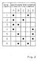
- a transmission diagram of a multi-stage automatic transmission for a motor vehicle with standard drive shown as in the prior art of DE 199 12 480 A1 known.
- a drive shaft of the automatic transmission is referred to, which is operatively connected to a (not shown) drive motor of the automatic transmission, for example via a torque converter oder.eine start-up clutch or a torsional damper or a dual-mass flywheel or a rigid shaft.
- AB is an output shaft of the automatic transmission, which is operatively connected to at least one drive axle of the motor vehicle.
- drive shaft AN and output shaft AB are coaxial with each other arranged.
- RS1, RS2 and RS3 designate three coupled single planetary gear sets arranged side by side in series in a transmission housing GG. All three planetary gear sets RS1, RS2, RS3 each have a sun gear SO1, SO2 and SO3, one ring gear HO1, HO2 and HO3, and a respective web ST1, ST2 and ST3 with planetary gears PL1, PL2 and PL3, each with sun and Combine ring gear of corresponding wheel set, up.
- a to E five switching elements are designated, wherein the first, third and fourth switching element A, C, D are designed as a brake and the second and fourth switching element B, E as a clutch.
- the respective friction linings of the five shift elements A to E are indicated as disk packs 100, 200, 300, 400 and 500 (each with outer and inner disks or steel and lining disks).
- the respective input elements of the five switching elements A to E are denoted by 120, 220, 320, 420 and 520, the respective output elements of the couplings B and E with 230 and 530.
- the kinematic connection of the individual wheelset elements and switching elements relative to each other and relative to drive and output shaft has already been described in detail above, as well as the spatial arrangement of these components.
- FIGS. 3 to 9 Four examples of a component assembly according to the invention will now be explained in detail in the following, based on the FIGS. 10 to 12 three exemplary component arrangements in conjunction with non-coaxial arrangement of input and output shafts, and based FIG. 13 a variation on the coupling of individual planetary gear set elements with each other.
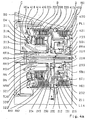
- Fig. 3 now shows a first schematic component arrangement, by way of example for the inventive solution of the problem.
- the inventive multi-stage automatic transmission has three coaxially arranged coupled single planetary gear sets RS1, RS2, RS3. Spatially seen, the second planetary gear set RS2 is arranged axially between the first and second planetary gear set RS1, RS3 and thereby adjoins axially directly to the third planetary gear set RS3. Furthermore, the multi-stage automatic transmission on five switching elements A to E.
- the first, third and fourth switching element A, C, D is in each case designed as a brake (in the example in each case as a multi-disc brake), the second and fifth Druckelemenet B, E each as a clutch (in each case as a multi-plate clutch).
- a sun gear SO3 of the third planetary gearset RS3 can be fixed via the brake A to a gearbox GG of the multi-stage automatic transmission.
- a drive shaft AN of the multi-stage automatic transmission is constantly with a Sun gear SO2 of the second planetary gearset RS2 connected.
- the drive shaft AN via the clutch B with a sun gear SO1 of the first planetary gear set RS1 and additionally or alternatively via the clutch E with a web ST1 of the first planetary gearset RS1 connectable.
- the sun gear SO1 of the first planetary gear set RS1 via the brake C and / or the web ST1 of the first planetary gearset RS1 via the brake D to the transmission housing GG can be fixed.
- An output shaft AB of the multi-stage automatic transmission is constantly connected to a ring gear HO1 of the first planetary gearset RS1, this ring gear HO1 is additionally connected in the illustrated exemplary coupling of the wheelset additionally with a web ST3 of the third planetary gear set RS3. Furthermore, a web ST2 of the second planetary gearset RS2 is constantly with a ring gear HO3. of the third planetary gear set RS3, as well as the web ST1 of the first planetary gear set RS1 constantly with a ring gear HO2 of the second planetary gearset RS2.
- the corresponding connecting element between the ring gear HO1 of the first planetary gearset RS1 and the web ST3 of the third planetary gear set RS3 is designed as a cylinder ZYL.
- This cylinder ZYL is connected on the one hand to the ring gear HO1 via a suitable operative connection, for example via a welding connection, and extends in the axial direction from the ring gear HO1 to beyond the ring gear HO3.
- the cylinder ZYL is connected on the side of the third planetary gearset RS3 facing away from the second planetary gearset RS2 via a suitable operative connection with a web plate STB3 of the web ST3, for example via a driving profile.
- the cylinder ZYL thus completely overlaps the second and third planetary gear sets RS2, RS3.
- the first planetary gear set RS1 is completely centered in the axial direction only by the drive shaft AN.
- the second, spatially seen average planetary gearset RS2 is only centrally penetrated by the drive shaft AN in the axial direction.
- AN, AB in the region of the third planetary gear set RS3, the drive shaft AN extends axially below the sun gear SO3 of the third planetary gearset RS3.
- the output shaft AB is mounted radially in this area on the drive shaft AN, wherein the output shaft AB operatively connected to the ring gear HO1 of the first planetary gearset RS1 completely passes through the third planetary gearset RS3 in the axial direction.
- the sun gear SO3 of the third planetary gearset RS3 in turn is mounted on the output shaft AB.
- the clutch E via which the drive shaft AN is connectable to the web ST1 of the first planetary gear set RS1, is spatially arranged between the first and second planetary gear sets RS1, RS2.
- the inner disks of the disk set 500 of the clutch E are exemplified here designed as steel plates, the outer disks of the disk set 500 of the clutch E accordingly as lining plates.
- An input element 520 of the clutch E is designed as an inner disk carrier and connected to the drive shaft AN.
- an output element 530 of the clutch E is designed as an outer disk carrier, which is connected both to the ring gear HO2 of the second planetary gearset RS2 and to the web ST1 of the first planetary gearset RS1.
- this outer disk carrier (530) of the clutch E is formed as a cylinder which is connected on one side with the ring gear HO2 of the second planetary gearset RS2 and on the other side with the web ST1 of the first planetary gearset RS1, and within which the disk set 500 of the clutch E is arranged.
- drive motor of the automatic transmission loaded slats 500 of the clutch E are arranged advantageously on a large diameter radially below the cylinder ZYL.
- this servo device 510 is mounted on the inner disk carrier (520) of the clutch E on the drive shaft AN and always rotates with the rotational speed of the drive shaft AN.
- the servo device of the fifth switching element can also be mounted directly on the drive shaft.
- the brake D via which the web ST1 of the first planetary gearset RS1 can be fixed, the brake C, via which the sun gear SO1 of the first planetary gear set RS1 can be fixed, and the clutch B, via which the sun gear SO1 of the first planetary gearset RS1 with the drive shaft AN is connectable, are arranged on the side of the first planetary gear set RS1, which is the clutch E opposite.
- An input element 220 of the clutch B is designed as an inner disk carrier and connected to the drive shaft AN. Accordingly, an output element 230 the clutch B is formed as an outer disk carrier which is connected to both the sun gear SO1 of the first planetary gear set RS1 and with an input member 320 of the brake C.
- this outer disk carrier (230) of the clutch B is designed as an opposite to the first planetary gear set RS1 open cylinder, the cylinder bottom partially axially adjacent to the first planetary gear set RS1 and partially axially to an inner disk support formed as input element 420 of the brake D, with the sun gear SO1 is connected and is mounted on the drive shaft AN.
- a disk set 200 with outer and lining disks of the clutch B and a servo device 210 of the clutch B are arranged.
- the servo 210 operates the fins 200 in opposite direction to the first planetary gear set RS1. Due to the wheelset concept, the clutch B is thermally very high load, as it is charged with the full drive torque of the operatively connected to the drive shaft AN drive motor of the automatic transmission and has to switch a comparatively high differential speed. Accordingly advantageous is the arrangement of the fins 200 of the clutch B on a large diameter.
- the input element 320 of the brake C designed as a lining disk carrier is connected to the outer disk carrier (230) of the clutch B on the side of the disks 200 facing away from the first planetary gearset RS1, wherein this operative connection can be designed, for example, as a driving profile, in particular with the same profile pitch as the disk driving teeth of the disk Outer plate carrier of the clutch B.
- a disk set 300 with steel and lining disks of the brake C is arranged at least largely radially in the axial direction below the disk set 200 of the clutch B, thus spatially within a clutch space of the clutch B, which is formed by the outer disk carrier (230) of the clutch B.
- the disk set 300 is axially adjacent directly to the inner disk carrier (220) of the clutch B, on which the servo device 210 or the first planetary gearset RS1 side facing away.
- a plate carrier for receiving steel plates of the brake C is integrated in a simple manner in a housing wall GW, which forms an outer wall of the gear housing GG, radially above a extending into the interior of the gear housing GG hub GN of this housing wall GW.
- housing wall GW is connected to the transmission housing GG, for example screwed.
- housing wall GW and hub GN can also be designed as separate, interconnected components.
- housing wall GW and transmission housing GG can be made in one piece.
- the input member 320 of the brake C is formed such that the lining blades of the disk pack 300 at outer outer diameter of the lining disc carrier (320) of the brake C are received.
- a servo 310 of the brake C is integrated in a simple manner in the housing wall GW, expediently radially above the hub GN, and actuates the blades 300 of the brake C axially in the direction of the first planetary gearset RS1.
- the housing wall GW a corresponding piston chamber (pressure chamber) and a displaceably mounted therein druckbeaufschlagbaren piston Servo 310 on, as well as a corresponding (not shown here) pressure medium supply to this piston chamber.
- a servo 410 of the brake D is also integrated in the housing wall GW, spatially seen radially above the servo 310 of the brake C.
- the housing wall GW thus also has a corresponding piston chamber (pressure chamber) and a displaceably mounted therein druckbeaufschlagbaren piston of the servo device 410, as well a corresponding (not shown here) pressure medium supply to this piston chamber.
- the servo device 410 additionally has an actuating punch 416 which completely overlaps the lamellae 200 of the clutch B and the servo device 210 of the clutch B partially in the axial direction and a piston force of the servo device 410 on the Slats 400 of the brake D transmits. Carried out as a thin-walled cylinder, this actuating punch 416 of the servo device 410 does not appreciably affect the radial installation space of the clutch B.
- both servos 310, 410 in the housing wall GW allows a very simple pressure medium supply to these two brakes C and D, as well as a simple, inexpensive for the assembly process assembly pre-assembly. Due to the special design of the servo device 410 with the actuating punch 416, an improved mountability of the brake D and the (pre-mounted) clutch B in the gearbox GG on the first planetary gear set RS1 is achieved, without the largest possible diameter for the slats 200 of the thermally high loaded clutch B to dispense, and without the largest possible diameter for the blades 400 of the static to dispense of all five switching elements on the highest loaded brake D.
- the adjacent to the first planetary gear set RS1 servo 210 of the second switching element B is closer to the first planetary RS1 arranged as the complete servo 310 of the third switching element C and as the pressure chamber of the servo 410 of the fourth switching element D.
- the fins 400 of the fourth Switching element D closer to the first planetary gear set RS1 arranged as the fins 200 of the second switching element B.
- the fins of the second switching element are arranged closer to the first planetary gear set than the fins of the fourth switching element, in which case arranged the slats of the third and fourth switching element adjacent to the housing outer wall and the servos of the third and fourth switching element are integrated in this housing outer wall, and in which case the slats of the third switching element radially below the slats d it are arranged fourth switching element.
- the brake A via which the sun gear SO3 of the third planetary gearset RS3 can be fixed, is arranged spatially on the side of the third planetary gearset RS3 facing away from the second planetary gearset RS2.
- an input element 120 of the brake A designed as an inner disk carrier adjoins axially the web ST3 of the third planetary gear set RS3, on the side remote from the second planetary gear set RS2.
- a disk set 100 of the brake A with outer and lining disks is on a large diameter in the range arranged facing away from the third planetary gearset RS3 outer wall of the transmission housing GG.
- a driving profile for the outer disks of the disk set 100 can be integrated in a simple manner in the transmission housing GG.
- a separate outer disk carrier may be provided which is connected by suitable means with the gear housing GG form, force or cohesive.
- a servo device 110 of the brake A for actuating the lamellae 100 is integrated in a simple manner in the outer wall of the gear housing GG and actuates the lamellae 100 axially in the direction of the three planetary gear sets RS1, RS2, RS3, said outer wall can of course also be designed as a housing cover , which is connected to the transmission housing GG, for example screwed.
- the transmission housing GG on a corresponding piston chamber (pressure chamber) and a displaceably mounted therein druckbeaufschlagbaren piston of the servo device 110, and a corresponding (not shown here) Druclanittelzucht to this piston chamber.
- the clutch A is therefore completely centered by the output shaft AB in the axial direction.
- component assembly is a spatially seen overall very slim, compact gear structure achieved, which is particularly suitable for use in a motor vehicle with standard drive, wherein the in Fig. 3 for simplicity not shown, operatively connected to the drive shaft AN drive motor of the automatic transmission is arranged on the side of the switching elements B, C, D, which is the first planetary gear set RS1, and wherein the clutch A is arranged correspondingly on the output side of the automatic transmission.
- circuit diagram of the multi-stage automatic transmission according to Fig. 3 corresponds to the in Fig. 2 illustrated circuit diagram.
- Fig. 3 The circuit diagram of the multi-stage automatic transmission according to Fig. 3 corresponds to the in Fig. 2 illustrated circuit diagram.
- DE 199 12 480 A1 are switchable by selective switching of two of the five switching elements so six forward gears group circuit.
- a housing wall GW bolted to the transmission housing GG and forms an outer wall in the direction of a (not shown) drive motor or in the direction of any existing, located outside of the transmission housing GG starting element (for example, a torque converter or a starting clutch) of the automatic transmission.
- This housing wall GW has in detail unspecified pressure fluid channels and can, for example, an oil pump for pressure and Take up lubricant supply to the automatic transmission.
- Axially in the direction of the interior of the gear housing GG extends a hub GN of the housing wall GW.
- this hub GN may be formed, for example, as a stator shaft of a torque converter. Radially inside the hub GN, the drive shaft AN of the automatic transmission runs and thereby penetrates the housing wall GW centric.
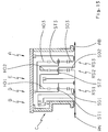
- the disk set 300 is arranged with steel and lining plates of the brake C, wherein the hub GN performs the function of a disk carrier for the steel plates of the disk set 300 and for this purpose has a corresponding Lamellenmittica, which in a corresponding inner profile engages the inner diameter of these steel plates.
- the servo 310 of the brake C is integrated in the housing wall GW.
- the housing wall GW has a corresponding piston or pressure chamber 311, and corresponding pressure medium channels 318 to this pressure chamber 311.
- a piston 314 druckbeauf Miltonbarer the servo device of the brake C is slidably mounted.
- this piston 314 actuates the disks 300 of the brake C against a restoring force of a restoring element 313 axially in the direction of the housing of the transmission housing.
- the restoring element 313 is formed here by way of example by two disk springs acting in series.
- the clutch B is disposed adjacent to the brake C.
- the disk pack 200 with outer and lining disks of the clutch B in the axial direction is at least largely arranged radially above the slats 300 of the brake C and the servo device of the clutch B axially adjacent to the disk set 300 of the brake C.
- the input element 220 of the clutch B is formed as an inner disk carrier.
- a disk-shaped portion 223 of this input member 220 axially adjacent to the disk set 300 is positively connected via a hub 223 with the drive shaft AN and extends radially outward to a diameter which is greater than the outer diameter of the blades 300 of the brake C.
- a cylindrical section 221 of this input element 220 adjoins the outer diameter of the disk-shaped section 223, extends axially in the direction of the housing wall GW and has a driving profile for the lining plates of the disk set 200 of the coupling B.
- the output member 230 of the clutch B is formed as an outer disk carrier, in the form of a direction of the housing wall GW open pot, within which the complete servo of the clutch B and the disk set 200 of the clutch B is arranged.
- a hub 233 of this outer disk carrier (230) is mounted on the drive shaft AN and connected on its side facing away from the housing wall GW side with the sun gear SO1 of the first planetary gearset RS1.
- a first disk-shaped portion 232 of the output member 230 connects to this hub 233 and extends radially outward to a diameter which is approximately less than the inner diameter the ring gear HO1 of the first planetary gear set RS1.
- the outer diameter of this first disc-shaped portion 232 is followed by a first cylinder-shaped Section 231 of the output member 230 and extends axially in the direction of the housing wall GW to the housing wall GW facing (front) portion of the hub 233.
- a second disc-shaped portion 235 of the output member 230 extends radially outward to a diameter which corresponds approximately to the outer diameter of the disk set 200 of the clutch B.
- a second cylindrical portion 234 of the output member 230 connects, which has a corresponding driving profile for receiving the outer disk of the clutch B and extends axially in the direction of the housing wall GW to beyond the disk set 200 of the clutch B addition , So into an area near the housing wall GW.
- the complete servo device of the clutch B is arranged within the previously described outer disk carrier (230) of the clutch B.
- the hub 233 of the outer disk carrier (230) of the clutch B a piston or pressure chamber 211 for a displaceably mounted in this piston chamber druckbeaufschlagbaren piston 215 of the servo device of the clutch B, and corresponding pressure medium channels to this pressure chamber 211.
- a pressurization of the pressure chamber 211 actuates the piston 215 the slats 200 of the clutch B against a restoring force of a return element 213 (here a plate spring, for example) axially in the direction of the housing wall GW, ie in the opposite direction to the first planetary gear set RS1.
- a return element 213 here a plate spring, for example
- the servo device of the clutch B in addition to a pressure compensation chamber 212 which is filled with lubricant without pressure.
- This pressure equalization chamber 212 adjoins the piston 214 on its side facing away from the pressure chamber 211 and is formed by this piston 214 itself and a baffle plate 215. Spatially, both the pressure chamber 211 and the pressure compensation chamber 212 are arranged within a cylinder space defined by the first cylinder disc-shaped portion 231 and the first cylindrical portion 232 of the outer disk carrier (230) of the clutch B is formed.
- the supply of pressure and lubricant to the pressure chamber 211 or pressure equalization chamber 212 takes place centrally from the drive shaft AN via corresponding feed bores 218 and 219, respectively.
- the pressure and lubricant guide within the drive shaft AN will be described later Fig. 6 explained in more detail.
- the input element 320 of the brake C designed as a lining disk carrier has a cylindrical section 321 with a driving profile for the lining disks of the brake C, which extends spatially radially below the cylindrical section 221 of the input element 220 of the clutch B.
- On the housing wall GW side facing this cylindrical portion 321 is followed by a disk-shaped portion 322 of the input member 320 of the brake C and extends above the disk set 300 of the brake C radially outward, up to the outer disk carrier (230) of the clutch B, with He is positively connected in the region of the open end of the second cylindrical portion 234.
- this positive connection is made via the same driving profile of the outer disk carrier (230) of the clutch B as for the outer disk of the disk set 200 of the clutch B.
- the slats 300 of the brake C spatially completely within a formed by the outer disk carrier of the clutch B clutch space of the clutch B are arranged.
- the disk set 400 with outer and lining disks of the brake D is seen in the axial direction at least substantially radially above the first cylindrical portion 231 of the outer disk carrier (230) of the clutch B.
- the gear housing GG has in this area in manufacturing technology advantageously a driving profile for receiving the Outer plate of the disk set 400 on. In this way, the largest possible slat diameter for the brake D is achieved, which is loaded statically of all five switching elements statically highest.
- the first web plate STB11 of the first planetary gearset RS1 adjoining the outer disk carrier (230) of the clutch B simultaneously forms the input element 420 of the brake C.
- a cylindrical section 421 of this input element 420 designed as an inner disk carrier adjoins the outer diameter of the first web plate STB11 axially in the direction of the housing wall GW, and has a corresponding driving profile for receiving the lining disks of the brake D.
- the servo device of the brake D has two piston or pressure chambers 411a and 411b which can be pressurized independently of each other, so that the actuating force acting on the lamellae 400 of the brake D is formed from the differential pressure of the two pressure chambers 411.
- the first Piston or pressure chamber 411a of the brake C is integrated together with its pressure medium channels 418 - in the housing wall GW, on a diameter above the piston 314 of the brake C, and acts on a piston 414, which is slidably mounted in a corresponding piston chamber of the housing wall GW is.
- the piston 414 in turn actuates an actuating punch 416, which forms the second pressure chamber 411b together with a portion of the transmission housing GG at the same time.
- the actuating punch 416 actuates the disks 400 of the brake D axially in the direction of the first planetary gearset RS1.
- the actuating punch 416 thus serves as an operative connection between the piston 415 and the disk set 400, thus directing the actuating force of the piston 415 on to the disk set 400.
- a return element which generates a restoring force for the piston 414 of the brake D and for this purpose on the one hand to the transmission housing GG and on the other hand supported on the actuating punch 416, wherein the Actuating punch 416 then passes through corresponding recesses of the return element in the axial direction.
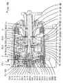
- Fig. 5 shown as a section gear cut.
- the only pressure medium space of the servo device of the brake D is denoted by 411, the restoring element with 413 acting on the piston 414 and penetrated by the actuating punch 416.
- a device for measuring a speed of the drive shaft AN integrated into the Gepatiusewand.GW.
- at least one speed sensor NAN is inserted into an axial bore of the housing wall GW and scans a correspondingly formed measuring surface of the disk-shaped portion 222 of the drive shaft connected to the inner disk carrier (220) of the clutch B axially preferably non-contact.
- the first planetary gearset RS1 connects axially to the servo of the clutch B and axially to the disk set 400 of the brake D.
- the sun gear SO1 of the first planetary gear set RS1 is only centrally penetrated by the drive shaft AN.
- drive and output shafts AN, AB are coaxial with each other.
- the web ST1 of the first planetary gear set RS1 is mounted on its side facing the transmission output side (ie on the side facing away from the three shift elements B, C, D) on the drive shaft AN via a slide bearing.
- the planet gears PL1 are rotatably mounted on planet pins, which are inserted into the web ST1 (planet carrier) and mesh with both the sun gear SO1 and the ring gear HO1 of the first planetary gear set RS1.
- the clutch E In the direction of the transmission output, the clutch E is followed axially by the first planetary gear set RS1, then by the second planetary gear set RS2, then by the second planetary gear set RS2, then by the third planetary gear set RS3, then by the third planetary gear set RS3 to the brake A finally an outer wall of the transmission housing GG.
- the clutch E is thus spatially arranged between the first and second planetary gear set RS1, RS2, the brake A on the outside of the three-shifting elements B, C, D opposite outside of the automatic transmission.
- the inner disks of a disk set 500 of the clutch E are designed as steel disks and the outer disks of the disk set 500 of the clutch E accordingly as lining disks.
- the input element 520 of the clutch E is designed as an inner disk carrier.
- a disk-shaped portion 522 of the input member 520 is positively connected via a hub 523 to the drive shaft AN and extends - axially immediately adjacent to the web ST1 of the first planetary gear set RS1 - radially outward to a diameter of the disk set 500 of the clutch E.
- a cylindrical portion 521 of the input member 520 In the area its outer diameter adjoins this disc-shaped portion 522, a cylindrical portion 521 of the input member 520 and extends axially in the direction of the second planetary gearset RS2. At its outer diameter, this cylindrical portion 521 has a driving profile for receiving the steel plates of the disk set 500.
- the servo device of the clutch E is arranged on the second planetary gearset RS2 side facing the inner disk carrier (520) of the clutch E seen in the axial direction radially above the hub 523 and includes a pressure chamber 511, a pressure compensation chamber 512, a piston 514, a baffle plate 515 and a return element 513.
- a support disc 517 arranged on the hub 523 axially fixed in the direction of the second planetary gearset RS2 via a locking ring and the hub 523 out (here, for example, via an O-ring) is sealed oil-tight.
- the piston 514 is axially displaceably mounted on the hub 523 and the outer diameter of the support plate 517 and sealed against both the hub 523 and against the outer diameter of the support plate 517 (here, for example via an O-ring) oil-tight, the pressure chamber 511 of piston 514 and support disk 517 is formed and spatially arranged on the first planetary gearset RS1 side facing the support disk 517 is arranged.
- the baffle plate 515 is axially adjacent to the disk-shaped portion 522 of the inner disk carrier (520) of the clutch E, abuts a shoulder of the hub 523, is compared to the axially displaceable piston 514 (here, for example, again via an O-ring) oil-tight sealed and forms together with the piston 514 on the first planetary gearset RS1 side facing the pressure compensation chamber 512.
- the pressure compensation chamber is pressureless filled with lubricant.
- the pressure medium supply to the pressure chamber 511 of the clutch E and the lubricant supply to the pressure compensation chamber 512 of the clutch E takes place via corresponding bores of the hub 523 centrally from the drive shaft AN, which in turn has corresponding pressure and lubricant guides 518, 519, which will be described later Fig. 6 will be explained in more detail.
- the piston 514 actuates the disks 500 of the clutch E axially in the direction of the first planetary gear set RS1, against a restoring force of the restoring element 513 (formed here as a plate spring, for example), which is inserted or preloaded between the piston 515 and the baffle plate 515 ,
- the sun gear SO2 of the second planetary gearset RS2 is - axially adjacent to the hub 523 of the input element 520 of the clutch E - positively connected via a driving profile with the drive shaft AN.
- the drive shaft AN fully penetrates the sun gear SO2 in the axial direction.
- the sun gear S02 is connected via the hub 532 to the drive shaft AN or that the hub 532 is connected via the sun gear SO2 to the drive shaft AN, in both cases structurally a suitable positive or non-positive Connection between sun gear SO2 and hub 532 is provided.
- sun gear SO2 and hub 532 may also be made in one piece or welded together.
- the planet gears PL2 of the second planetary gearset RS2 mesh with both the sun gear SO2 and the ring gear HO2 of the second planetary gearset RS2 and are rotatably mounted on the web ST2 of the second planetary gearset RS2.
- the web ST2 On its side facing the third planetary gearset RS3, the web ST2 has a web plate STB2 which extends radially outward and is connected at its outside diameter to the ring gear HO3 of the third planetary gearset RS3, here for example via a welded connection.
- this connection can also be executed in a form-fitting manner in another embodiment, also web plate STB2 and ring gear HO3 can be made in one piece.
- the ring gear HO2 of the second planetary gear set RS2 is connected via the output element 530 of the clutch E to the web ST1 of the first planetary gearset RS1.
- This output element 530 is designed as a cylinder which extends axially from the ring gear HO1 of the first planetary gear set RS1 to the ring gear HO2 of the second planetary gearset RS2 and thereby completely overlaps the clutch E in the axial direction. At its inner diameter, this cylinder has a driving profile for receiving the outer disk of the disk set 500 of the clutch E.
- Fig. 4b illustrated exemplary one-piece design of ring gear HO2 and output member 530 is very advantageous in terms of assembly.
- the output element 530 also allows the arrangement of the disk set 500 of the clutch E on a comparatively large diameter.
- ring gear HO2 and output element 530 can also be designed as separate components.
- the web ST1 of the first planetary gear set RS1 has a second web plate STB12 which is mounted on the drive shaft AN and extends radially outwards to the output element 530 of the clutch E.
- the second web plate STB12 on a driving profile, which engages in a corresponding driving profile of the output element 530 of the clutch E.
- this positive connection can be designed such that the web plate STB12 engages in the driving profile of the output element 530 for the outer disk of the clutch E.
- the web ST3 of the third planetary gear set RS3 is connected both to the output shaft AB and to the ring gear HO1 of the first planetary gearset RS1.
- a thin-walled cylinder ZYL is provided, which extends in the axial direction radially above the clutch E and the two planetary gear sets RS2, RS3, starting from the ring gear HO1 to over the ring gear HO3 of the third planetary gearset RS3 over , The cylinder ZYL thus completely overlaps both the clutch E and the two planetary gear sets RS2, RS3.
- the cylinder ZYL is welded to the ring gear HO1, but can of course be connected in another embodiment, for example, form-fitting with the ring gear HO1.
- On the other side of the cylinder ZYL is connected via a driving profile with a web plate STB3 of the web ST3, which is arranged on the side facing away from the second planetary gearset RS2 side of the third planetary gearset RS3.
- this connection between web ST3 and cylinder ZYL constructive be designed differently, for example as a welded joint.
- the output shaft AB is connected on the second planetary gearset RS2 side facing the third planetary gearset RS3 with the web ST3, wherein the output shaft AB, the sun gear SO3 of the third planetary gearset RS3 centrally completely passes through and is mounted on the drive shaft AN.
- output shaft AB and web ST3 are designed as one-piece forging component, which is connected in a form-fitting manner to an output flange ABF on the side of the third planetary gearset RS3 facing away from the second planetary gearset RS2, which is in turn supported on the output-side outer wall of the transmission housing GG with a broad bearing base.
- this parking lock gear PSR has a toothing in which a (in Fig. 4b simplified) parking lock pawl PSK can engage to set the output shaft AB.
- a corresponding contour is provided on the outer surface of the cylinder ZYL, which scans a corresponding, designated NAB speed sensor radially non-contact.
- the output rotational speed or output rotational direction can also be measured via the parking brake toothing.
- two such output speed sensors or a combined from two sensors output speed sensor may be provided in addition to the absolute speed the output shaft AB to determine their direction of rotation.
- the sun gear SO3 of the third planetary gearset RS3 is mounted on the output shaft AB and connected on the side facing away from the second planetary gearset RS2 side of the third planetary gearset RS3 with the input element 120 of the brake A, in the example shown by means of welded connection.
- the input element 120 of the brake A can also be suspended in a correspondingly designed driving profile of the sun gear SO3.
- the here designed as in the direction of transmission output steel sheet pot input member 120 has at its cylindrical portion 121 a driving profile for receiving lining plates of the disk set 100 of the brake A. In this case, this plate pack 100 is arranged on a comparatively large diameter, spatially seen in addition to the ring gear HO3 of the third planetary gearset RS3.
- the transmission housing GG has in this area a driving profile for receiving outer disks of the disk set 100 of the brake A, so at the same time takes over the function of an outer disk carrier for the brake A in manufacturing and assembly technology favorable way.
- a separate outer disk carrier be provided for the brake A, which is then connected via suitable means to the transmission housing.
- the servo device of the brake A is also integrated directly into the transmission housing GG in manufacturing and assembly technology favorable manner.
- the output-side outer wall of the transmission housing GG has a corresponding piston or pressure chamber 111, and corresponding Pressure medium channels 118 for this pressure chamber 111.
- a pressurizable piston 114 of the servo device of the brake A is slidably mounted.
- this piston 114 actuates the lamellae 100 of the brake A against a restoring force of a restoring element 113 (designed here by way of example as a disk spring) axially in the direction of the third planetary gearset RS3.
- the output-side outer wall of the transmission housing is designed as a separate, connected to the transmission housing cover, which can accommodate, for example, both the servo of the brake A and the outer disks of the brake A.
- gear design is also characterized by a small number of thrust bearings and rotating sealing rings.
- thrust bearings only a total of eight thrust bearings designated AX1 to AX8 are provided, with even only two different sizes.
- RR1 to RR4 rotating sealing rings (“rectangular rings") are required in order to dynamically seal the individual pressure and lubricant supply against each other and to the outside.
- all four rotating sealing rings RR1 to RR4 are inserted into corresponding grooves of the drive shaft AN and can be designed geometrically equal in an advantageous manner.
- FIG. 6 a section through the drive shaft AN, in Fig. 4a / 4b designated XY.
- a thin-walled tube ROH is used centrally in the drive shaft AN oil-tight, for example by means of press fit or bonding. Within this tube ROH, the lubricant is guided, which can be branched off via radial openings of the drive shaft opening into the interior of the tube ROH for the lubrication of various components and for the filling of pressure compensation chambers.
- this second component arrangement is based on the above Fig. 3 described first component assembly according to the invention with unchanged kinematic coupling of the three individual planetary gear sets RS1, RS2, RS2 with each other, with the five switching elements A to E and drive and output shafts AN, AB.
- the arrangement of drive shaft AN, output shaft AB, the three Planetenrad suitsn.RS1, RS2, RS3, the clutch E as the fifth switching element and the brake A as a first switching element substantially corresponds to in Fig.
- the spatial arrangement of the clutch formed as a second switching element B and each formed as a brake third and fourth switching element C, D on the (not shown) drive motor side facing the first planetary gear set RS1 opposite Fig. 3 modified, in particular the spatial arrangement of the disk set 400 of the brake D.
- Fig. 3 The arrangement of the lamellae 300 and the servo device 310 of the brake C in the axial direction are unchanged radially above the hub GN of the gearbox housing wall GW, the complete integration of the servo C 310 in the housing wall GW, the integration of the servo D 410 of the brake D. in the housing wall GW, as well as the actuation directions of all three servos 210, 310, 410 of the three switching elements B, C, D.
- the clutch B is now - viewed in the direction of the first planetary gearset RS1 - arranged axially completely next to the brake C, in particular axially adjacent to the blades 300 of the brake C.
- the input member 220 of the clutch B is formed as an inner disk carrier and is adjacent in the area in he is connected to the drive shaft AN, axially directly to the housing wall GW.
- the output element 230 of the clutch B is - similar to in Fig. 3 - Formed as a cylindrical outer disk carrier, within which the disk set 200 and the servo device 210 of the clutch B is arranged.
- the input element 320 of the brake C - as in Fig. 3 - Connected via the output member 230 of the clutch B to the sun gear SO1 of the first planetary gearset RS1.
- the input element 320 is formed as an inner disk carrier, now mounted on the hub GN of the housing wall GW and takes on lining disks of the disk set 300 now on an inner diameter of these lining disks.
- a corresponding outer disk carrier of the brake C for receiving the outer disk of the laminated core 300 at the outer diameter is in the in Fig. 7 illustrated example, in the gear housing fixed housing wall GW integrated on a diameter larger than the servo 310 of the brake C and smaller of the servo device 410 of the brake D.
- the outer disc carrier of the brake C may be formed as a separate, gearbox fixed component.
- the disk set 400 of the brake D is now seen in axialler direction at least substantially above the disk set 300 of the brake C, axially immediately adjacent to the integrated in the housing wall GW servo 410.
- the gear housing GG assumes the function of an outer disk carrier for the brake in the example shown D.
- the outer disk carrier of the brake D can also be formed as a separate, gear housing fixed component.
- the input element 420 of the brake D is designed as an inner disk carrier, which is connected according to the kinematic connection with the web ST1 of the first planetary gearset RS1. This inner disk carrier engages over the clutch B in the axial direction radially completely. Seen spatially, the clutch B is thus not only closer to the first planetary gear set RS1 arranged as the brake C, but also closer to the first planetary gear set RS1 as the brake D.
- the inner disk carrier (420) of the brake D does not appreciably affect the radial installation space of the clutch B. If this permits the available radial installation space for the transmission housing GG, the diameter of the lamellae 400 of the conceptionally statically highest loaded brake D in simpler Way opposite Fig. 3 be enlarged, in favor of a construction length reduction.
- this fourth component arrangement according to the invention is again based on the previously described Fig. 3 described first component assembly according to the invention, with unchanged kinematic coupling of the three individual planetary gear sets RS1, RS2, RS3 with each other, with the five switching elements A to E and drive and output shafts AN, AB.
- the arrangement of drive shaft AN, output shaft AB, the three planetary gear sets RS1, RS2, RS3, the clutch E as Fifth switching element and the brake A as a first switching element substantially corresponds to in Fig.
- the lamellae 400 of the brake D are arranged on the side of the first planetary gearset RS1 facing away from the second planetary gearset RS2, axially adjacent to and radially above the first planetary gearset RS1.
- the servo device 410 of the brake D is now arranged above the first planetary gearset RS1, integrated into the transmission housing GG and actuates the lamellae 400 of the brake D axially in the direction of the housing wall GW.
- the brake C adjoins the housing wall GW in the direction of the transmission housing interior, wherein both the servo C 310 of the brake C and an outer disk carrier for receiving outer disks of the disk set 300 of the brake C are integrated into the housing wall GW, on a large diameter near one Inner diameter of the gearbox GG.
- the housing wall GW thus forms a coupling space of the brake C.
- the clutch B is at least partially disposed within this coupling space of the brake C.
- the input element 220 of the clutch B is designed as an outer disk carrier, geometrically as a in the direction of the first planetary gear set RS1 open pot, whose disc-shaped bottom immediately adjacent to the housing wall GW and is connected to the drive shaft AN, and within the cylindrical portion of the disk set 200 and the servo 210 of the clutch B are arranged.
- the servo device 210 which always rotates at rotational speed of the drive shaft AN, is mounted on the drive shaft AN and actuates the disks 200 axially in the direction of the first planetary gear set RS1.
- the slats 200 of the clutch B are arranged at least predominantly spatially below the slats 300 of the brake C. According to the thermally different load of the clutch B and brake C, the disk set 200 of the clutch B but can also continue axially in the direction of the first planetary gearset RS1 extend as the disk set 300 of the brake C.
- output element 230 of the clutch B and input element 320 of the brake C are both formed as an inner disk carrier.
- the inner disk carrier (320) of the brake C is connected via the inner disk carrier (230) of the clutch B to the sun gear SO1 of the first planetary gearset RS1.
- the inner disk carrier (230) of the clutch B is formed such that it receives the lining disks of the disk set 200 at the inner diameter. For example, if a one-piece design of the inner disk carrier (230, 320) provided by clutch B and brake C, it may be appropriate that the inner disk carrier of the clutch B - different from the illustration in Fig.
- the servo device of the clutch B is expediently then on the first planet wheel set facing side of the fins of the clutch B and actuates these blades in the direction of the housing wall, ie in the opposite direction to the first planetary gear set RS1.
- FIG. 10 now shows an exemplary variation of the schematic component assembly according to Fig. 3 , now with non-coaxial arrangement of input and output shaft.
- drive shaft AN and output shaft AB now arranged axially parallel to each other.
- a spur gear STST For the kinematic connection of the output shaft AB to the here permanently connected to the web ST3 of the third planetary RS3 ring gear HO1 of the first planetary gear set RS1 is provided a spur gear STST, which is spatially arranged on the opposite side of the second planetary gearset RS2 planetary gearset RS3, axially between the third planetary gearset RS3 and the clutch A.
- a first spur gear STR1 of this spur gear STST is fixedly connected to the web ST3 of the third planetary gearset RS3 and mounted by way of example on the sun gear SO3 of the third planetary gearset RS3.
- a second spur gear STR2 of this spur gear STST meshes with the first spur gear STR1 and is fixedly connected to the output shaft.
- a multi-spur gear stage may also be provided, for example with three spur gears and then again the same direction of rotation of the input and output shafts.
- the drive shaft AN penetrates the housing wall GW and all three planetary gear sets RS1, RS2, RS3 centric and is mounted on the housing wall GW opposite, cover-shaped outer wall of the gear housing GG.
- the drive motor, not shown for simplicity, of the automatic transmission is therefore arranged on the side of the housing wall GW facing away from the planetary gear sets.
- the drive shaft could also penetrate the housing wall GW opposite the lid-shaped outer wall of the transmission housing GG and the drive motor could be located close to the clutch A on that side of the transmission.
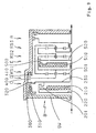
- Fig. 11 shows an exemplary second component assembly with axially parallel to each other arranged drive and output shafts AN, AB.
- the two brakes C, D are no longer spatially arranged next to the first planetary gear set RS1, but now next to each other in a range above the planetary gear sets, here in the area above the two planetary gear sets RS2 and RS3, on a large diameter near the inner diameter of the transmission housing GG.
- the servo 210 of the unchanged on the side facing away from the second Planetenradsatze RS2 side of the first planetary gearset RS1 clutch B now actuates the fins 200 of the clutch B axially in the direction of the first planetary gearset RS1.
- the brake C is arranged closer to the clutch B than the brake D, both with respect to the respective disc pack and to the respective servo device.
- the disk set 300 of the brake C seen in the axial direction is arranged predominantly radially over the second planetary gearset RS2.
- the servo 310 of the brake C actuates the blades 300 of the brake C axially in the direction of the clutch B.
- the brake D connects to the brake C.
- the fins 400 of the brake D are in the example shown in an area above the second and third planetary gearset RS2, RS3. arranged.
- the servo 410 operates the blades 400 in the opposite direction to the brake C (or to the clutch B).
- the servos 310 and 410 of the two brakes C, D are immediately adjacent, so they are manufacturing and assembly technology low here in a common, gearbox fixed outer disk carrier, which receives the outer disks of both disk sets 300, 400, 400 are integrated.
- the blades 300 and 400 have the same diameter (identical part concept).
- the transmission housing GG in this section has a suitable driving profile for receiving the outer disk of the disk set 300 of the brake C and / or the outer disk of the disk set 400 of the brake D.
- the drive motor operatively connected to the drive input shaft AN (not shown) exemplarily on the second Planetenradsatze RS2 opposite side of the third planetary gear set RS3 arranged, ie on the transmission side on which the brake A and the output shaft AB operatively connected spur gear are arranged, ie on the opposite side of the clutch transmission side.
- the brake A is adjacent to the outer wall facing the drive motor (which can also be embodied as a housing cover) of the transmission housing GG.
- Fig. 12 now shows an exemplary third component assembly with axially parallel to each other arranged drive and output shafts AN, AB.
- the brakes A, C and D arranged side by side on the inner diameter of the gear housing GG, wherein the brake A is connected axially in the direction of the spur gear to the brake D.
- the blades 100, 300 and 400 of the three brakes A, C, D have the same diameter (identical part concept).
- the brakes A and D are summarized as an assembly.
- the servo 110, 410 of both brakes A, D are arranged immediately adjacent to each other.
- the servo device 410 of the brake D is arranged on the side facing away from the brake C side of the disk set 400 of the brake D and actuates these blades 400 axially toward the clutch B.
- the servo device 110 of the brake A is on the brake D side facing the disk set 100th arranged the brake A and actuates these blades 100 axially in the brake D (or clutch B) opposite direction.
- the web plate of the web ST3 of the third planetary gear set RS3 facing away from the second planetary gear set RS2 is designated STB3.
- the input element 120 (inner disk carrier) of the brake A which is connected to the sun gear SO3 of the third planetary gearset RS3, extends radially outward.
- the output shaft operatively connected to the spur gear with the two spur gears STR1 and STR2.
- a hub of the first spur gear STR1 is mounted on the drive shaft AN and passes through the input element 120 of the brake A and the sun gear SO3 of the third planetary gear set RS3 centrally and is connected on the second planetary gear set RS2 side facing the web ST3 with this web ST3.
- the spur gear is thus arranged directly on an outer wall of the transmission housing GG.
- the bearing of the first spur gear STR1 can be embodied on this outer wall, in the illustrated example on a corresponding cylindrical projection of the outer wall.
- this outer wall can also be designed as a housing cover. In the in Fig.
- the spur gear is arranged on the side facing the drive motor side of the automatic transmission, so that the drive shaft to the hub of the first spur gear STR1 penetrates centrally and the hubs of the first spur gear STR1 is additionally mounted on the drive shaft AN.
- the expert will also represent by similar modifications an angular position of drive and output shaft of the automatic transmission, for example by adding a bevel gear instead the previously described spur gear for a front-wheel drive with built-in longitudinal direction to the drive motor.
- FIG. 13 now shows an exemplary variation of the schematic component assembly according to Fig. 3 , With a modified coupling of individual wheelset elements, said kinematic coupling of the wheelset already in the prior art DE 199 12 480 A1 is known. In contrast to Fig.
- the ring gear HO1 of the first planetary gear set RS1 and the web ST2 of the second planetary gearset RS2 and the output shaft AB are constantly connected to each other, as well as the web ST3 of the third planetary gear set RS3 constantly with the ring gear HO2 of the second planetary gearset RS2 and the web ST1 of the first planetary gearset RS1 constantly with the ring gear HO3 of the third planetary gearset RS3.
- the kinematic coupling of the three individual planetary gear sets RS1, RS2, RS3 to the five switching elements A to E and to the drive shaft opposite Fig. 3 unchanged.
- the spatial arrangement of the five switching elements A to E relative to each other and to the three planetary gear sets RS1, RS2, RS3 is opposite Fig. 3 unchanged.
Landscapes
- Engineering & Computer Science (AREA)
- General Engineering & Computer Science (AREA)
- Mechanical Engineering (AREA)
- Structure Of Transmissions (AREA)
Applications Claiming Priority (2)
| Application Number | Priority Date | Filing Date | Title |
|---|---|---|---|
| DE10333430A DE10333430A1 (de) | 2003-07-23 | 2003-07-23 | Mehrstufen-Automatgetriebe mit drei Planetenradsätzen |
| PCT/EP2004/006964 WO2005019690A1 (de) | 2003-07-23 | 2004-06-28 | Mehrstufen-automatgetriebe mit drei planetenradsätzen |
Publications (2)
| Publication Number | Publication Date |
|---|---|
| EP1646808A1 EP1646808A1 (de) | 2006-04-19 |
| EP1646808B1 true EP1646808B1 (de) | 2009-01-21 |
Family
ID=34042039
Family Applications (1)
| Application Number | Title | Priority Date | Filing Date |
|---|---|---|---|
| EP04740365A Expired - Lifetime EP1646808B1 (de) | 2003-07-23 | 2004-06-28 | Mehrstufen-automatgetriebe mit drei planetenradsätzen |
Country Status (6)
| Country | Link |
|---|---|
| EP (1) | EP1646808B1 (https=) |
| JP (1) | JP2006528318A (https=) |
| KR (1) | KR100939884B1 (https=) |
| CN (1) | CN1860314B (https=) |
| DE (2) | DE10333430A1 (https=) |
| WO (1) | WO2005019690A1 (https=) |
Families Citing this family (4)
| Publication number | Priority date | Publication date | Assignee | Title |
|---|---|---|---|---|
| US6929576B2 (en) * | 2003-10-24 | 2005-08-16 | General Motors Corporation | Power transmission for a vehicle |
| US6913556B2 (en) | 2003-10-24 | 2005-07-05 | General Motors Corporation | Power transmission for a vehicle |
| US6923742B2 (en) * | 2003-10-24 | 2005-08-02 | General Motors Corporation | Power transmission for a vehicle |
| DE102007014150A1 (de) * | 2007-03-23 | 2008-09-25 | EGS Entwicklungsgesellschaft für Getriebesysteme mbH | Lastschaltbares Mehrstufengetriebe |
Family Cites Families (17)
| Publication number | Priority date | Publication date | Assignee | Title |
|---|---|---|---|---|
| US4070927A (en) * | 1976-06-04 | 1978-01-31 | General Motors Corporation | Planetary gearing arrangement for a transmission |
| JPS61596Y2 (https=) * | 1980-12-23 | 1986-01-10 | ||
| JPH0621620B2 (ja) * | 1987-07-28 | 1994-03-23 | 日産自動車株式会社 | 自動変速機の歯車変速装置 |
| JP3102047B2 (ja) * | 1991-03-20 | 2000-10-23 | 日産自動車株式会社 | 自動変速機の遊星歯車列 |
| JP3102075B2 (ja) * | 1991-07-26 | 2000-10-23 | 日産自動車株式会社 | 自動変速機のクラッチ構造 |
| DE4224360A1 (de) * | 1991-07-26 | 1993-01-28 | Nissan Motor | Automatikgetriebeauslegung |
| US5295924A (en) * | 1992-12-07 | 1994-03-22 | Ford Motor Company | Multiple speed nonsynchronous automatic transmission for motor vehicles |
| US5533945A (en) * | 1994-07-06 | 1996-07-09 | Chrysler Corporation | Five-speed automatic transmission |
| JPH08210445A (ja) * | 1995-02-06 | 1996-08-20 | Honda Motor Co Ltd | 遊星歯車式変速機 |
| JP3414077B2 (ja) * | 1995-03-24 | 2003-06-09 | アイシン・エィ・ダブリュ株式会社 | 車両用自動変速機 |
| JP3682354B2 (ja) * | 1997-02-13 | 2005-08-10 | ジヤトコ株式会社 | 自動変速機用歯車変速装置 |
| DE19912480B4 (de) * | 1999-03-22 | 2006-03-16 | Zf Friedrichshafen Ag | Automatisch schaltbares Kraftfahrzeuggetriebe |
| DE19912481A1 (de) * | 1999-03-22 | 2000-09-28 | Zahnradfabrik Friedrichshafen | Automatisch schaltbares Kraftfahrzeuggetriebe |
| US6471616B2 (en) * | 2001-02-15 | 2002-10-29 | General Motors Corporation | Power transmission with friction launch torque transmitting mechanism in forward and reverse |
| US20020183160A1 (en) * | 2001-06-05 | 2002-12-05 | Chi-Kuan Kao | Six-speed planetary transmission mechanisms with two clutches and three brakes |
| US6652411B2 (en) * | 2001-09-26 | 2003-11-25 | General Motors Corporation | Multi-speed transmission family with three planetary gear sets and five rotating torque transmitting mechanisms |
| DE10162883B4 (de) * | 2001-12-20 | 2013-02-07 | Zf Friedrichshafen Ag | Mehrstufengetriebe |
-
2003
- 2003-07-23 DE DE10333430A patent/DE10333430A1/de not_active Withdrawn
-
2004
- 2004-06-28 EP EP04740365A patent/EP1646808B1/de not_active Expired - Lifetime
- 2004-06-28 CN CN2004800208150A patent/CN1860314B/zh not_active Expired - Fee Related
- 2004-06-28 DE DE502004008923T patent/DE502004008923D1/de not_active Expired - Lifetime
- 2004-06-28 WO PCT/EP2004/006964 patent/WO2005019690A1/de not_active Ceased
- 2004-06-28 KR KR1020067001311A patent/KR100939884B1/ko not_active Expired - Fee Related
- 2004-06-28 JP JP2006520698A patent/JP2006528318A/ja not_active Withdrawn
Also Published As
| Publication number | Publication date |
|---|---|
| KR20060059968A (ko) | 2006-06-02 |
| KR100939884B1 (ko) | 2010-01-29 |
| CN1860314A (zh) | 2006-11-08 |
| DE502004008923D1 (de) | 2009-03-12 |
| JP2006528318A (ja) | 2006-12-14 |
| EP1646808A1 (de) | 2006-04-19 |
| WO2005019690A1 (de) | 2005-03-03 |
| CN1860314B (zh) | 2010-07-14 |
| DE10333430A1 (de) | 2005-02-10 |
Similar Documents
| Publication | Publication Date | Title |
|---|---|---|
| EP1902232B1 (de) | Mehrstufengetriebe | |
| EP1864034B1 (de) | Mehrstufengetriebe | |
| EP1504202B1 (de) | Mehrstufengetriebe | |
| EP1678430B1 (de) | Mehrstufen-automatgetriebe mit drei planetenradsätzen | |
| DE102004050123A1 (de) | Lastschaltgetriebe für ein Fahrzeug | |
| DE3741757C2 (de) | Automatikgetriebe | |
| EP1774198B1 (de) | Mehrstufen-automatgetriebe | |
| DE102004051610B4 (de) | Lastschaltgetriebe für ein Fahrzeug | |
| EP1658453B1 (de) | Mehrstufen-automatgetriebe mit drei planetenradsätzen | |
| EP1646809A1 (de) | Mehrstufen-automatgetriebe mit drei planetenradsätzen | |
| EP1784586B1 (de) | Mehrstufen-automatgetriebe | |
| EP1676052B1 (de) | Mehrstufen-automatgetriebe mit drei planetenradsätzen | |
| EP1646808B1 (de) | Mehrstufen-automatgetriebe mit drei planetenradsätzen | |
| EP1646810B1 (de) | Mehrstufen-automatgetriebe mit drei planetenradsätzen | |
| EP1784585B1 (de) | Mehrstufen-automatgetriebe | |
| EP1787042B1 (de) | Mehrstufen-automatgetriebe | |
| EP1781963B1 (de) | Mehrstufen-automatgetriebe | |
| DE20320470U1 (de) | Mehrstufen-Automatgetriebe mit drei Planetenradsätzen | |
| DE20320468U1 (de) | Mehrstufen-Automatgetriebe mit drei Planetenradsätzen | |
| DE20320469U1 (de) | Mehrstufen-Automatgetriebe mit drei Planetenradsätzen | |
| DE20320466U1 (de) | Mehrstufen-Automatgetriebe mit drei Planetenradsätzen | |
| DE20320477U1 (de) | Mehrstufen-Automatgetriebe mit drei Planetenradsätzen |
Legal Events
| Date | Code | Title | Description |
|---|---|---|---|
| PUAI | Public reference made under article 153(3) epc to a published international application that has entered the european phase |
Free format text: ORIGINAL CODE: 0009012 |
|
| 17P | Request for examination filed |
Effective date: 20051001 |
|
| AK | Designated contracting states |
Kind code of ref document: A1 Designated state(s): DE FR GB SE |
|
| DAX | Request for extension of the european patent (deleted) | ||
| RBV | Designated contracting states (corrected) |
Designated state(s): DE FR GB SE |
|
| GRAP | Despatch of communication of intention to grant a patent |
Free format text: ORIGINAL CODE: EPIDOSNIGR1 |
|
| GRAS | Grant fee paid |
Free format text: ORIGINAL CODE: EPIDOSNIGR3 |
|
| GRAA | (expected) grant |
Free format text: ORIGINAL CODE: 0009210 |
|
| RAP1 | Party data changed (applicant data changed or rights of an application transferred) |
Owner name: ZF FRIEDRICHSHAFEN AG |
|
| AK | Designated contracting states |
Kind code of ref document: B1 Designated state(s): DE FR GB SE |
|
| REG | Reference to a national code |
Ref country code: GB Ref legal event code: FG4D Free format text: NOT ENGLISH |
|
| REF | Corresponds to: |
Ref document number: 502004008923 Country of ref document: DE Date of ref document: 20090312 Kind code of ref document: P |
|
| PG25 | Lapsed in a contracting state [announced via postgrant information from national office to epo] |
Ref country code: SE Free format text: LAPSE BECAUSE OF FAILURE TO SUBMIT A TRANSLATION OF THE DESCRIPTION OR TO PAY THE FEE WITHIN THE PRESCRIBED TIME-LIMIT Effective date: 20090421 |
|
| PLBE | No opposition filed within time limit |
Free format text: ORIGINAL CODE: 0009261 |
|
| STAA | Information on the status of an ep patent application or granted ep patent |
Free format text: STATUS: NO OPPOSITION FILED WITHIN TIME LIMIT |
|
| 26N | No opposition filed |
Effective date: 20091022 |
|
| GBPC | Gb: european patent ceased through non-payment of renewal fee |
Effective date: 20090628 |
|
| PG25 | Lapsed in a contracting state [announced via postgrant information from national office to epo] |
Ref country code: GB Free format text: LAPSE BECAUSE OF NON-PAYMENT OF DUE FEES Effective date: 20090628 |
|
| PGFP | Annual fee paid to national office [announced via postgrant information from national office to epo] |
Ref country code: FR Payment date: 20100709 Year of fee payment: 7 |
|
| REG | Reference to a national code |
Ref country code: FR Ref legal event code: ST Effective date: 20120229 |
|
| PG25 | Lapsed in a contracting state [announced via postgrant information from national office to epo] |
Ref country code: FR Free format text: LAPSE BECAUSE OF NON-PAYMENT OF DUE FEES Effective date: 20110630 |
|
| PGFP | Annual fee paid to national office [announced via postgrant information from national office to epo] |
Ref country code: DE Payment date: 20200617 Year of fee payment: 17 |
|
| REG | Reference to a national code |
Ref country code: DE Ref legal event code: R119 Ref document number: 502004008923 Country of ref document: DE |
|
| PG25 | Lapsed in a contracting state [announced via postgrant information from national office to epo] |
Ref country code: DE Free format text: LAPSE BECAUSE OF NON-PAYMENT OF DUE FEES Effective date: 20220101 |