EP1645746B1 - Zylinderkopf für eine Brennkraftmaschine - Google Patents
Zylinderkopf für eine Brennkraftmaschine Download PDFInfo
- Publication number
- EP1645746B1 EP1645746B1 EP20050019394 EP05019394A EP1645746B1 EP 1645746 B1 EP1645746 B1 EP 1645746B1 EP 20050019394 EP20050019394 EP 20050019394 EP 05019394 A EP05019394 A EP 05019394A EP 1645746 B1 EP1645746 B1 EP 1645746B1
- Authority
- EP
- European Patent Office
- Prior art keywords
- cylinder head
- web
- bores
- cylinder
- engine
- Prior art date
- Legal status (The legal status is an assumption and is not a legal conclusion. Google has not performed a legal analysis and makes no representation as to the accuracy of the status listed.)
- Expired - Lifetime
Links
Images
Classifications
-
- F—MECHANICAL ENGINEERING; LIGHTING; HEATING; WEAPONS; BLASTING
- F02—COMBUSTION ENGINES; HOT-GAS OR COMBUSTION-PRODUCT ENGINE PLANTS
- F02F—CYLINDERS, PISTONS OR CASINGS, FOR COMBUSTION ENGINES; ARRANGEMENTS OF SEALINGS IN COMBUSTION ENGINES
- F02F1/00—Cylinders; Cylinder heads
- F02F1/24—Cylinder heads
- F02F1/26—Cylinder heads having cooling means
- F02F1/36—Cylinder heads having cooling means for liquid cooling
- F02F1/38—Cylinder heads having cooling means for liquid cooling the cylinder heads being of overhead valve type
Definitions
- the invention relates to a cylinder head for an internal combustion engine according to the features in the preamble of patent claim 1.
- a cylinder head which has a transverse to the cylinder head longitudinal axis extending, flooded with coolant slot between the cylinder bores. This measure is used to cool the thermally highly loaded land area of the cylinder head.
- a disadvantage of this embodiment is a relatively large necessary web width to edit the cylinder head in this area mechanically.
- the object of the present invention is to show a new method, such as the thermal expansion of a narrow web in the cylinder direction; between two cylinders in a cylinder head can be minimized.
- the design allows the distribution of the holes according to static conditions, d. H. in accordance with the occurring thermal deformations during operation of the internal combustion engine.
- the thermal expansion of the land area can be determined by means of a numerical simulation, and then the relief holes can be optimally arranged.
- several holes can be stochastically distributed or arranged symmetrically to the combustion chamber roofs or a combination of both types of distribution.
- the embodiment according to claim 2 allows the introduction of a plurality of holes in the direction of the cylinder axis, even with narrow webs.
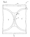
- a cylinder head 1 is bounded on two outer sides by a respective first outer wall 1a and a second outer wall 1b. Between the outer walls 1 a, 1 b are two half dome-shaped, incorporated in the cylinder head 1 combustion chamber roofs 4, 4 ', which are separated by a web 3, which is also part of the cylinder head 1. Between the combustion chamber roofs 4, 4 'are In the present case, the bores 5 are distributed symmetrically with respect to the combustion chamber roofs 4, 4 'and are largely aligned in the direction of a cylinder axis, not shown, in the web area 3 in a crankcase-side sealing surface. A series of bores 5 extends in a straight line in the expansion direction of the web 3 between the combustion chamber roofs 4, 4 ', two further rows of bores 5 extend coaxially to the combustion chamber roofs 4, 4' in the web area 3.
- the holes 5 in the exemplary embodiment have a bore diameter of 0.05 mm and a bore depth of 1 mm.
- the bore diameter may also be between 0.01 and 1 mm and the bore depth between 0.1 and 8 mm.
- 4 ' is also a stochastic distribution of the holes 5 is possible or a combination of the two types of distribution.
- the holes 5 were made by laser drilling, but can also be produced by ultrasonic drilling.
Landscapes
- Engineering & Computer Science (AREA)
- Chemical & Material Sciences (AREA)
- Combustion & Propulsion (AREA)
- Mechanical Engineering (AREA)
- General Engineering & Computer Science (AREA)
- Cylinder Crankcases Of Internal Combustion Engines (AREA)
Description
- Die Erfindung betrifft einen Zylinderkopf für eine Brennkraftmaschine gemäß der Merkmale im Oberbegriff des Patentanspruchs 1.
- Aus der
DE 100 09 776 C1 ist ein Zylinderkopf bekannt, der zwischen den Zylinderbohrungen einen quer zur Zylinderkopflängsachse verlaufenden, mit Kühlmittel gefluteten Schlitz aufweist. Diese Maßnahme dient zur Kühlung des thermisch hoch belasteten Stegbereichs des Zylinderkopfes. - In der
US 4,436,066 A ist ein Zylinderkopf-für eine Brennkraftmaschine beschrieben, der im Stegbereich zwischen zwei Zylinderbohrungen einen quer zur Zylinderkopflängsachse ausgerichteten Schlitz aufweist. In diesen Schlitz dehnt sich beim Betrieb der Brennkraftmaschine das heiße Zylinderkopfmaterial aus, wodurch die Materialspannungen im heißen Stegbereich minimiert werden. Der Schlitz wird durch vorzugsweise durch spanabhebende Bearbeitung, d. h. Fräsen gebildet. - Nachteilig bei dieser Ausgestaltung ist eine relativ große notwendige Stegbreite, um den Zylinderkopf in diesem Bereich mechanisch bearbeiten zu können.
- Aufgabe der vorliegenden Erfindung ist es, eine neue Methode aufzuzeigen, wie die thermische Ausdehnung eines schmalen Steges in Zylinderrichtung; zwischen zwei Zylindern in einem Zylinderkopf minimiert werden kann.
- Diese Aufgabe wird durch das Merkmal im kennzeichnenden Teil des Patentanspruchs 1 gelöst. Durch die erfindungsgemäße Ausgestaltung dehnt sich das Stegmaterial bei Erhitzung in Richtung der Bohrung, anstelle in Längsrichtung oder in Richtung des Kurbelgehäuses aus. Durch diese Maßnahme kann die Zylinderkopfdichtung entweder im Stegbereich einfacher, d. h. auch kostengünstiger ausgeführt, oder der Stegbereich noch schlanker ausgelegt werden.
- Weiter erlaubt die Ausgestaltung die Verteilung der Bohrungen nach statischen Bedingungen, d. h. entsprechend den auftretenden thermischen Deformationen beim Betrieb der Brennkraftmaschine. Beispielsweise kann mittels einer numerischen Simulation die Wärmedehnung des Stegbereiches ermittelt und anschließend können die Entlastungsbohrungen optimal angeordnet werden. Abhängig von der Wärmedehnung können mehrere Bohrungen stochastisch verteilt oder symmetrisch zu den Brennraumdächern oder aus einer Kombination beider Verteilungsarten angeordnet werden.
- Die Ausgestaltung gemäß Patentanspruch 2 erlaubt die Einbringung einer Vielzahl von Bohrungen in Richtung der Zylinderachse, selbst bei schmalen Stegen.
- Durch die Herstellung der Bohrung mittels Laser- bzw. Ultraschallbohren gemäß Patentanspruch 3 kann diese schnell und kostengünstig eingebracht werden.
- Im Folgenden ist die Erfindung anhand eines bevorzugten Ausführungsbeispieles in einer einzigen Figur näher erläutert.
- Fig. 1
- zeigt schematisch die Aufsicht auf einen Ausschnitt einer Montageflä- che eines Zylinderkopfs.
- Ein Zylinderkopf 1 wird an zwei Außenseiten durch jeweils eine erste Außenwand 1 a und eine zweite Außenwand 1 b begrenzt. Zwischen den Außenwänden 1 a, 1 b befinden sich zwei halbe kalottenförmige, in den Zylinderkopf 1 eingearbeitete Brennraumdächer 4, 4', die von einem Steg 3, der ebenfalls Bestandteil des Zylinderkopfs 1 ist, getrennt sind. Zwischen den Brennraumdächern 4, 4' befinden sich im Stegbereich 3 in einer kurbelgehäuseseitigen Dichtfläche 2 Bohrungen 5. Die Bohrungen 5 sind im vorliegenden Fall symmetrisch zu den Brennraumdächern 4, 4' verteilt und sind weitgehend in Richtung einer nicht dargestellten Zylinderachse ausgerichtet. Eine Reihe mit Bohrungen 5 erstreckt sich geradlinig in Ausdehnungsrichtung des Steges 3 zwischen den Brennraumdächern 4, 4', zwei weitere Reihen mit Bohrungen 5 erstrecken sich koaxial zu den Brennraumdächern 4, 4' im Stegbereich 3.
- Die Bohrungen 5 weisen im Ausführungsbeispiel einen Bohrungsdurchmesser von 0,05 mm sowie eine Bohrungstiefe von 1 mm auf. In weiteren Ausführungsbeispielen kann der Bohrungsdurchmesser auch zwischen 0,01 und 1 mm liegen und die Bohrungstiefe zwischen 0,1 und 8 mm betragen. Neben einer symmetrischen Verteilung der Bohrungen 5 um die Brennraumdächer 4, 4' ist auch eine stochastische Verteilung der Bohrungen 5 möglich bzw. eine Kombination aus beiden Verteilungsarten.
- Die Bohrungen 5 wurden mittels Laserbohren hergestellt, können aber auch durch Ultraschallbohren erzeugt werden.
- Durch die erfindungsgemäße Ausgestaltung wird die Deformation und somit Undichtigkeit zwischen den Brennraumdächern 4, 4' durch die thermische Ausdehnung der Stege 3 verringert. Ferner wird eine damit einhergehende Verringerung der Flächenpressung einer Zylinderkopfdichtung erzielt. Der Einsatz dieser Perforation ist auch bei modernen Reihenmotoren mit extrem schmalen Stegen 3 möglich. Darüber hinaus handelt es sich um ein schnelles und kostengünstiges Verfahren, um oben genannte Nachteile zu vermeiden.
-
- 1
- Zylinderkopf
- 1a
- erste Außenwand
- 1 b
- zweite Außenwand
- 2
- Dichtfläche
- 3
- Steg
- 4, 4'
- Brennraumdach
- 5
- Bohrung
Claims (3)
- Zylinderkopf (1) für eine Brennkraftmaschine mit einer kurbelgehäuseseitigen Dichtfläche (2) in der mindestens zwei von einem Steg (3) getrennte Brennraumdächer (4, 4') angeordnet sind, wobei in dem Steg (3) eine Bohrung (5), die weitgehend in Richtung einer Zylinderachse ausgerichtet ist, angeordnet ist,
dadurch gekennzeichnet, dass im Stegbereich mehrere Bohrungen (5) symmetrisch zu den Brennraumdächern (4, 4') und/oder stochastisch verteilt angeordnet sind. - Zylinderkopf nach Patentanspruch 1,
dadurch gekennzeichnet, dass die Bohrungen (5) einen Bohrungsdurchmesser zwischen 0,01 und 1 mm, sowie eine Bohrungstiefe zwischen 0,1 und 8 mm aufweisen. - Zylinderkopf nach einem der Patentansprüche 1 oder 2
dadurch gekennzeichnet, dass die Bohrungen (5) mittels Laserbohren oder Ultraschallbohren erzeugt sind.
Applications Claiming Priority (1)
| Application Number | Priority Date | Filing Date | Title |
|---|---|---|---|
| DE200410049301 DE102004049301A1 (de) | 2004-10-09 | 2004-10-09 | Zylinderkopf für eine Brennkraftmaschine |
Publications (2)
| Publication Number | Publication Date |
|---|---|
| EP1645746A1 EP1645746A1 (de) | 2006-04-12 |
| EP1645746B1 true EP1645746B1 (de) | 2012-06-06 |
Family
ID=35708718
Family Applications (1)
| Application Number | Title | Priority Date | Filing Date |
|---|---|---|---|
| EP20050019394 Expired - Lifetime EP1645746B1 (de) | 2004-10-09 | 2005-09-07 | Zylinderkopf für eine Brennkraftmaschine |
Country Status (2)
| Country | Link |
|---|---|
| EP (1) | EP1645746B1 (de) |
| DE (1) | DE102004049301A1 (de) |
Family Cites Families (3)
| Publication number | Priority date | Publication date | Assignee | Title |
|---|---|---|---|---|
| DE2354798C3 (de) * | 1973-11-02 | 1981-08-06 | Klöckner-Humboldt-Deutz AG, 5000 Köln | Zylinderkopf für Hubkolbenbrennkraftmaschinen |
| IT1118653B (it) | 1979-05-23 | 1986-03-03 | Fiat Veicoli Ind | Testa cilindri per motori ad accensione per compressione del tipo a precamera di combustione |
| DE10009776C1 (de) | 2000-03-01 | 2001-04-05 | Daimler Chrysler Ag | Brennkraftmaschine |
-
2004
- 2004-10-09 DE DE200410049301 patent/DE102004049301A1/de not_active Ceased
-
2005
- 2005-09-07 EP EP20050019394 patent/EP1645746B1/de not_active Expired - Lifetime
Also Published As
| Publication number | Publication date |
|---|---|
| EP1645746A1 (de) | 2006-04-12 |
| DE102004049301A1 (de) | 2006-04-20 |
Similar Documents
| Publication | Publication Date | Title |
|---|---|---|
| DE60006755T2 (de) | Zylinderkopfdichtung mit einem Gasaustrittbereich | |
| EP1898195A2 (de) | Temperatursensor mit bearbeitbarer Front | |
| EP2195520A1 (de) | Zylinderkurbelgehäuse für einen verbrennungsmotor | |
| DE102004044851A1 (de) | Zylinderkopfdichtung | |
| EP1482218B1 (de) | Zylinderkopfdichtung | |
| DE602004003781T2 (de) | Zylinderkopfdichtung | |
| DE69827190T2 (de) | Metalldichtung mit örtlich wärmebehandelter Wulst | |
| DE102017206716A1 (de) | Zylinderblock eines Verbrennungsmotors | |
| EP2623759B1 (de) | Brennkraftmaschine mit zumindest drei Zylindern | |
| DE3142344A1 (de) | Zylinderkopfdichtung | |
| EP2295916B1 (de) | Stapelscheiben-Kühler, Verwendung des Stapelscheiben-Kühlers und Brennkraftmaschine mit einem Stapelscheiben-Kühler | |
| DE102005037384A1 (de) | Brennkraftmaschine mit zumindest zwei Zylindern | |
| DE10326520B4 (de) | Kurbelgehäuse für eine Brennkraftmaschine | |
| EP1875110B1 (de) | Flachdichtung, insbesondere zylinderkopfdichtung | |
| EP1645746A1 (de) | Zylinderkopf für eine Brennkraftmaschine | |
| DE10009776C1 (de) | Brennkraftmaschine | |
| DE19840379C2 (de) | Zylinderblock einer flüssigkeitsgekühlten Brennkraftmaschine | |
| DE102010055160A1 (de) | Verfahren zur Herstellung eines Zylinderkurbelgehäuses sowie Zylinderkurbelgehäuse | |
| DE102016214224B4 (de) | Zylinderblock für einen mehrzylindrigen Verbrennungsmotor | |
| DE102022102472A1 (de) | Kühlmitteldurchgang in einer zwischenzylinderbohrung für verbesserten kavitationsschutz in einem motorblock | |
| DE10334044B4 (de) | Zylinderkopfdichtung | |
| EP1519028A1 (de) | Zylinderkopf einer Brennkraftmaschine | |
| DE102004058646A1 (de) | Mehrzylindrige Brennkraftmaschine | |
| EP1752643A1 (de) | Brennkraftmaschine mit zumindest zwei Zylindern | |
| AT414012B (de) | Flüssigkeitsgekühlte brennkraftmaschine mit zumindest zwei zylindern |
Legal Events
| Date | Code | Title | Description |
|---|---|---|---|
| PUAI | Public reference made under article 153(3) epc to a published international application that has entered the european phase |
Free format text: ORIGINAL CODE: 0009012 |
|
| AK | Designated contracting states |
Kind code of ref document: A1 Designated state(s): AT BE BG CH CY CZ DE DK EE ES FI FR GB GR HU IE IS IT LI LT LU LV MC NL PL PT RO SE SI SK TR |
|
| AX | Request for extension of the european patent |
Extension state: AL BA HR MK YU |
|
| 17P | Request for examination filed |
Effective date: 20060428 |
|
| AKX | Designation fees paid |
Designated state(s): DE FR GB IT |
|
| GRAP | Despatch of communication of intention to grant a patent |
Free format text: ORIGINAL CODE: EPIDOSNIGR1 |
|
| GRAS | Grant fee paid |
Free format text: ORIGINAL CODE: EPIDOSNIGR3 |
|
| GRAA | (expected) grant |
Free format text: ORIGINAL CODE: 0009210 |
|
| AK | Designated contracting states |
Kind code of ref document: B1 Designated state(s): DE FR GB IT |
|
| REG | Reference to a national code |
Ref country code: GB Ref legal event code: FG4D Free format text: NOT ENGLISH |
|
| REG | Reference to a national code |
Ref country code: DE Ref legal event code: R096 Ref document number: 502005012777 Country of ref document: DE Effective date: 20120802 |
|
| PLBE | No opposition filed within time limit |
Free format text: ORIGINAL CODE: 0009261 |
|
| STAA | Information on the status of an ep patent application or granted ep patent |
Free format text: STATUS: NO OPPOSITION FILED WITHIN TIME LIMIT |
|
| 26N | No opposition filed |
Effective date: 20130307 |
|
| REG | Reference to a national code |
Ref country code: DE Ref legal event code: R097 Ref document number: 502005012777 Country of ref document: DE Effective date: 20130307 |
|
| PGFP | Annual fee paid to national office [announced via postgrant information from national office to epo] |
Ref country code: DE Payment date: 20140919 Year of fee payment: 10 |
|
| REG | Reference to a national code |
Ref country code: FR Ref legal event code: PLFP Year of fee payment: 11 |
|
| PGFP | Annual fee paid to national office [announced via postgrant information from national office to epo] |
Ref country code: GB Payment date: 20150924 Year of fee payment: 11 |
|
| PGFP | Annual fee paid to national office [announced via postgrant information from national office to epo] |
Ref country code: FR Payment date: 20150928 Year of fee payment: 11 |
|
| PGFP | Annual fee paid to national office [announced via postgrant information from national office to epo] |
Ref country code: IT Payment date: 20150924 Year of fee payment: 11 |
|
| REG | Reference to a national code |
Ref country code: DE Ref legal event code: R119 Ref document number: 502005012777 Country of ref document: DE |
|
| PG25 | Lapsed in a contracting state [announced via postgrant information from national office to epo] |
Ref country code: DE Free format text: LAPSE BECAUSE OF NON-PAYMENT OF DUE FEES Effective date: 20160401 |
|
| GBPC | Gb: european patent ceased through non-payment of renewal fee |
Effective date: 20160907 |
|
| REG | Reference to a national code |
Ref country code: FR Ref legal event code: ST Effective date: 20170531 |
|
| PG25 | Lapsed in a contracting state [announced via postgrant information from national office to epo] |
Ref country code: GB Free format text: LAPSE BECAUSE OF NON-PAYMENT OF DUE FEES Effective date: 20160907 Ref country code: FR Free format text: LAPSE BECAUSE OF NON-PAYMENT OF DUE FEES Effective date: 20160930 |
|
| PG25 | Lapsed in a contracting state [announced via postgrant information from national office to epo] |
Ref country code: IT Free format text: LAPSE BECAUSE OF NON-PAYMENT OF DUE FEES Effective date: 20160907 |