EP1645465A1 - System for mounting a headlamp in a vehicle and vehicle with such a mounting system - Google Patents
System for mounting a headlamp in a vehicle and vehicle with such a mounting system Download PDFInfo
- Publication number
- EP1645465A1 EP1645465A1 EP05292044A EP05292044A EP1645465A1 EP 1645465 A1 EP1645465 A1 EP 1645465A1 EP 05292044 A EP05292044 A EP 05292044A EP 05292044 A EP05292044 A EP 05292044A EP 1645465 A1 EP1645465 A1 EP 1645465A1
- Authority
- EP
- European Patent Office
- Prior art keywords
- projector
- vehicle
- rotation
- center
- ramp
- Prior art date
- Legal status (The legal status is an assumption and is not a legal conclusion. Google has not performed a legal analysis and makes no representation as to the accuracy of the status listed.)
- Granted
Links
Images
Classifications
-
- B—PERFORMING OPERATIONS; TRANSPORTING
- B60—VEHICLES IN GENERAL
- B60Q—ARRANGEMENT OF SIGNALLING OR LIGHTING DEVICES, THE MOUNTING OR SUPPORTING THEREOF OR CIRCUITS THEREFOR, FOR VEHICLES IN GENERAL
- B60Q1/00—Arrangement of optical signalling or lighting devices, the mounting or supporting thereof or circuits therefor
- B60Q1/02—Arrangement of optical signalling or lighting devices, the mounting or supporting thereof or circuits therefor the devices being primarily intended to illuminate the way ahead or to illuminate other areas of way or environments
- B60Q1/04—Arrangement of optical signalling or lighting devices, the mounting or supporting thereof or circuits therefor the devices being primarily intended to illuminate the way ahead or to illuminate other areas of way or environments the devices being headlights
- B60Q1/0491—Shock absorbing devices therefor
Definitions
- the present invention relates to a mounting system of a projector on a motor vehicle for moving the projector relative to the vehicle in a frontal collision with an obstacle.
- This mounting system allows, in particular, a rotation of the projector relative to the vehicle.
- the invention has applications in the field of motor vehicles and, in particular, in the field of pedestrian safety and motor vehicle safety in the event of a frontal collision or collision with a pedestrian.
- an obstacle may be a pedestrian impact or a frontal impact.
- the frontal impact is a collision of the vehicle, at different speeds and at different angles, with a fixed or moving obstacle.
- Pedestrian impact is a collision with an adult or child pedestrian at different speeds.
- the projector 2 also comprises fixing lugs, or connecting members, ensuring a displacement of the projector 2 towards the rear of the vehicle 1, during a frontal impact or a pedestrian impact.
- the connecting members comprise two different guiding means ensuring, respectively, a sliding of the searchlight 2 towards the rear and towards the side of the wing 6 of the vehicle 1.
- the sliding of the searchlight 2 toward the rear of the vehicle 1 and the sliding of the projector 2 to the side of the wing 6 of the vehicle 1 are two linear displacements, combined.
- the displacement of the projector 2 towards the side of the wing 6 of the vehicle 1 allows a clearance of the projector 2.
- this clearance towards the side of the wing 6 of the projector 2 causes a collision of the projector 2 against the edge of the wing 6 of the vehicle.
- the projector 2 then completes its movement in the engine environment of the vehicle. In other words, the projector 2 crashes against one or more elements of the engine environment of the vehicle 1, thus creating a lot of damage in the engine environment of the vehicle 1, in addition to the demolition of the wing 6 of the vehicle 1.
- Moving the projector 2 towards the rear of the vehicle 1 allows to absorb some of the energy generated by the shock, because this movement is limited by the engine environment of the vehicle. However, this energy absorption is not sufficient to meet the new standard; the protection of the pedestrian is not sufficiently ensured.
- the sliding kinematics of the projector 2 comprises, in case of pedestrian impact, a significant risk of hurting the pedestrian. Indeed, during a pedestrian impact, the sliding of the projector 1 towards the rear of the vehicle propels the pedestrian on the side area 5 of the projector 2, which is a rigid area of said projector, therefore dangerous for the pedestrian.
- the invention provides a mounting system of a projector on a motor vehicle, wherein, during a pedestrian impact, the projector is rotated around a selected center of rotation.
- the projector comprises a first connecting element and the motor vehicle comprises a second connecting element.
- These connecting elements are curved and adapted to each other to rotate the projector during a frontal impact or a pedestrian impact.
- the invention also relates to a motor vehicle comprising at least one projector mounted on the motor vehicle by means of a mounting system according to the invention.
- the invention relates to a mounting system of a projector on a motor vehicle for a rotation of the projector relative to the vehicle, in a collision.
- An example of a mounting system according to the invention is shown in Figure 2.
- This Figure 2 shows a projector, a vehicle and the mounting system of the projector on the vehicle very schematically.
- FIG. 2 A first block represents the vehicle 1 and a second block represents the projector 2.
- the mounting system is shown on the second block, for simplification.
- the projector 2 is attached to the vehicle 1 by the mounting system of the invention.
- This mounting system comprises two connecting elements 7 and 8.
- the first connecting element 7 is mounted on the projector 2 in the side area 5 of the projector.
- a side zone is a zone of the headlamp 2 comprising the rigid housing of the headlamp 2.
- the second connecting element 8 is mounted on the vehicle 1, for example on the chassis of the vehicle.
- the connecting elements 7 and 8 have structures adapted to slide one into the other.
- the connecting element 8 is a guide device for supporting and guiding the connecting element 7. It constitutes a guide path for the connecting element 7.
- the connecting element 8 can be, for example , a rail.
- the connecting element 8 can also be a slide or any other structure allowing the sliding of the connecting element 7.
- the connecting element 7 is a guided element, adapted to slide in the connecting element 8.
- This connecting element 7 may be, for example, a slideway.
- the connecting element 7 and the connecting element 8 may be of identical length, as shown in FIG. 2.
- the connecting element 7, or the guided element 7, may also be shorter in length than the connecting element 8, or the rail 8.
- the rail 8 and the guided element 7 have a curved or circular shape, providing circular movement to the guided element 7.
- the rail 8 is fixed on the vehicle 1 so that the projector 2 is movable relative to the vehicle 1.
- the displacement of the guided element 7, in the rail 8, leads automatically a rotation of the projector 2.
- the guided element 7 and the rail 8 are mounted at least partially around a center of rotation 9 of the projector 2.
- This center of rotation 9 is defined by simulation and / or experimentation for an optimal rotation of the projector 2.
- the rail 8 and the guided element 7 are circumscribed, the rail 8 being external to the guided element 7.
- the guided element 7 and the rail 8 form arcs mounted around the center of rotation 9.
- the center of rotation 9 thus forms the center of circles passing through the guided element 7 and the rail 8, the distance between the center of rotation 9 and the rail 8 being greater than the distance between the center of rotation 9 and the guided element 7.
- the guided element 7 and the rail 8 are fixed to each other by detachable fixing means, that is to say able to detach or break, in case of choc.
- detachable fixing means that is to say able to detach or break, in case of choc.
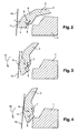
- FIGS. 2, 3, 4 show the kinematics of a vehicle 1 colliding with an impactor 10.
- This impactor 10 represents a pedestrian or any other object colliding with the vehicle 1 frontally. Throughout the description, the impactor 10 will be considered as a pedestrian, knowing that it may be any other frontal obstacle.
- the impactor 10 is shown in FIGS. 2, 3, 4 by a solid line substantially inclined
- the impactor 10 comes into contact with a surface 11 of the lateral zone 5 of the headlamp 2.
- the intensity of the collision force between the impactor 10 and the headlamp 2 causes the breaking of the means of fixing the guided element 7 on the rail 8, in the case where there are such fastening means.
- the collision force at the moment of impact, causes the guided element 7 to move on the rail 8, as shown in FIG. 3.
- This displacement of the guided element 7 on the rail 8 causes the projector to tilt. 2 relative to the vehicle 1.
- This tilting of the projector 2 corresponds to a rotational movement of the projector 2 around the center of rotation 9.
- This rotary movement is performed in a direction of rotation 12 defined in the design of the projector 2.
- the rotation of the projector 2 has the effect of moving the impact surface 11 of the impactor 10.
- This surface 11 moves towards the central zone 4, or frontal area, of the projector 2, that is to say towards the the most flexible area of the projector 2 since it is the center of the protective glass 3.
- the impact surface 11 moved is named and referenced "impact surface 13".
- This rotation of the projector 2 releases said projector to the side of the wing of the vehicle 1 thus allowing the projector 2 not to hit the engine environment of the vehicle 1 during its rotation.
- FIG. 4 The final position of the projector 2 with respect to the impactor 10 and the vehicle 1 at the end of the displacement of the guided element 7 on the rail 8, is shown in FIG. 4.
- the end of the displacement of the guided element 7 on the rail 8 causes the end of the rotation of the projector 2 around the center of rotation 9. This displacement ends when the guided element 7 reaches a stop on the rail 8, or when the guided element 7 leaves the rail 8, as shown in Figure 4.
- the impact surface 13 is on the frontal zone 4 of the protective glass 3.
- This surface 13 is the final impact surface of the impactor 10 on the projector 2.
- This final surface 13 is a flexible area of the projector 2, so a less dangerous area for the pedestrian, when it is a pedestrian impact.
- the rotation of the projector 2 absorbs part of the energy generated by the collision between the impactor 10 and the vehicle 1.
- This energy absorption has the effect of significantly reducing the energy received by the impactor 10, in particular, when the impactor 10 represents a pedestrian. The safety of the pedestrian is improved.
- this rotation of the projector 2 allows the projector does not enter, with all the force of the shock, in the vehicle 1.
- the vehicle engine 1, which is one of the most expensive elements of the vehicle 1, and that the engine environment, are thus protected. The damage of the vehicle 1 is therefore limited and the repair costs of the vehicle 1 are considerably reduced.
- the rotation of the projector 2 is established around the center of rotation 9.
- This center of rotation 9 is defined according to the optimum final position of the projector 2 with respect to the impactor 10.
- the position of the center of rotation 9 is preset for each projector according, in particular, to the normal position of the projector 2 on the vehicle 1 and the final position desired after rotation. Examples of definition of the center of rotation 9 are shown in FIGS. 5 and 6.
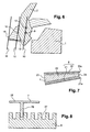
- FIG. 5 shows the center of rotation 9 of the projector 2 relative to different positions of the impactor 10.
- the center of rotation 9 is determined at the design of the projector 2, it can be chosen at any point of the projector 2.
- the choice the center of rotation 9 is preferably performed by simulation and optimization. It is defined taking into account the shape of the projector 2 and that of the vehicle 1. It is also defined according to an initial position of the projector 2 and an optimal final position of the projector on the impactor 10.
- the position initial is the position in which the projector 2 is located, in normal operation.
- the impact zone 15 is chosen as the initial position.
- the final position corresponds to the position of the projector 2 against the impactor 10, at the end of shock.
- the end zone 4 of the headlamp 2 is chosen as the final position.
- the end position is represented in FIG. 5 by the impact surface 16.
- the center of rotation 9 can also be mobile. In this case, the position of the center of rotation 9 depends on the intensity of the collision force between the vehicle 1 and the impactor 10 and the initial and final positions of the projector 2 relative to the impactor 10.
- the center of rotation 9 is centered on the center of gravity of the projector 2, resulting in the conversion of the translational energy into rotational energy in an optimal manner.
- the center of rotation 9 is different from the center of gravity, as shown in FIG. 6.
- FIG. 6 shows an optimal position of the center of rotation 9, in the case where the center of rotation 9 is not the center of gravity 17 of the projector 2.
- the center of rotation 9 is chosen to be aligned with the center of gravity 17. This alignment is represented by a straight line 19. This straight line 19 is preferably parallel to the impactor 10 in the initial position and to the impactor 10 in the final position. It is perpendicular to the impact force 18, representative of the energy generated during the collision between the vehicle 1 and the impactor 10.
- the center of rotation 9 can be any point of the 19.
- the center of rotation 9 is also chosen as a function of the distance between the impact force 18 and the center of rotation 9 and the distance between the center of gravity 17 and the center of rotation 9.
- the rotation of the projector 2 is optimized when the distance from the impact force 18 to the center of rotation 9 is greater than the distance from the center of gravity 17 to the center of rotation 9.
- the rotation of the projector 2 causes the projector to absorb a portion of the energy generated by the collision of the vehicle 1 with the impactor 10.
- a portion of the energy generated by the collision is dissipated in the projector 2 in rotation.
- the guided element 7 and the rail 8 comprise mechanical braking structures. These mechanical braking structures make it possible to slow down the rotational movement of the projector 2, thus absorbing part of the energy of the collision.
- Figure 7 shows a first embodiment of this braking system.
- the rail 8 comprises two bars of structures 20 and 21 rectilinear, non-parallel, capable of forming at their ends 20e and 21e a non-right angle.
- the rail 8 has a tapered shape.
- the guided element 7 comprises a tapered piece 22, the shape of which is adapted to fit between the bars 20 and 21 of the rail 8.
- the part 22 of the guided element 7 has a degressive width from one end 23 to one end 24.
- the bars 20 and 21 of the rail 8 receive the piece 22 of the guided element 7.
- the guided element 7 and the rail 8 are made of flexible materials. These flexible materials have the property of taking over, partially or totally, their shape and their volume, after having lost them by compression or extension.
- the piece 22 of the guided element 7 then constitutes a deformable membrane which transmits to the bars 20 and 21 of the rail 8, the impact force received by the vehicle 1 during the collision with the impactor 10.
- the tapered shape of the rail 8 slows the displacement of the guided element 7 on the rail 8, causing a slowing down of the rotational movement of the projector 2.
- the rail 8 has a crenellated shape, that is to say it has several slots 27.
- the guided element 7 has a T-shape intended to snap on the rail 8.
- the guided element 7 comprises a branch 28 and a branch 29, perpendicular to the branch 28.
- the branch 29 has a length adapted to the height of the crenellations 27 of the rail 8.
- the guided element 7 moves on the rail 8 by successive breaks.
- the branch 29 jumps from a slot 27 to another slot, each jump absorbing a little energy.
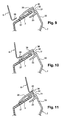
- a sliding ramp is provided to ensure the release of the projector 2 to the wing 6 of the vehicle 1, without damaging the wing or the lining of this wing.
- This embodiment is shown in FIGS. 9 to 11 showing the kinematics of the system during a collision.
- FIG. 9 represents the wing 6 of the vehicle and an example of a floodlight 2 equipped with a sliding ramp 36.
- the projector 2 comprises a rigid bar 30, for example of metal.
- This bar 30 has at its end a U-shaped piece 31, having a leg 32 and a leg 33.
- the leg 33 is located between the protective glass 3 and the bar 30.
- the leg 32 is located in the engine environment of the vehicle.
- the protective glass 3 is generally embedded in the space formed by the legs 32 and 33.
- the wing 6 of the vehicle has an L-shaped stamped end. This end constitutes the fallen edge of the wing. In the normal position of the projector 2, the end 35 is moved away from the leg 32.
- the projector 2 In the collision of the vehicle with the impactor, the projector 2, by a rotation movement described above, is released to the side of the wing 6 of the vehicle. During the rotation of said headlamp, the leg 32 can hit the fallen edge 35 of the wing 6 of the vehicle, thus causing the deformation of the wing 6.
- the sliding ramp 36 of the invention makes it possible to slide the leg 32 under the fallen edge 35 of the wing 6.
- the ramp 36 is fixed in the lateral zone 5 of the headlamp 2, on the leg 32 of the piece 31.
- the ramp 36 forms an inclined plane, between end 37 and one end 38, allowing said ramp to slide under the fallen edge 35 of wing 6.
- the inclined shape of the ramp 36 imposes the direction of displacement of the floodlight 2 under the fallen edge 35 of the wing 6, as shown in FIG. 10.
- the rotation of the floodlight 2 causes the end 37 of the ramp 36 to come into contact with each other. with the flanged edge 35 of the flange 6.
- the end 37 is adapted to fit under the dropped edge 35, so that the ramp 36 slides under said fallen edge 35, avoiding any collision between the dropped edge 35 and the leg 32.
- FIG. 11 shows the projector 2 at the end of its displacement under the fallen edge 35 of the wing 6.
- the inclination of the ramp 36 has allowed the leg 32 to slide under the fallen edge 35 of the wing 6. There is therefore, between the leg 32 and the flange 35 of the wing 6, a protective space including the ramp 36.
- the leg 32 of the piece 31 does not hit the edge fell 35 of the wing 6 regardless of the type of projector.
- a piece 39 is fixed on the protective glass 3.
- This piece 39 for example made of a plastic material, is fastened to the end 37 of the ramp 36, for example by overmolding.
- This piece 39 forms a leaf spring, located at the foot of the ramp 36.
- This compression of the piece 39 allows the dropped edge 35 to be placed on the same level as the end 37 of the ramp 36.
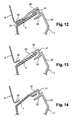
- FIG. 13 shows a third variant of the ramp 36.
- a hump 40 is fixed on the protective glass 3.
- This hump 40 is situated between the leg 32 of the piece 31 and the fallen edge 35 of the wing 6.
- the hump 40 is formed by an inclined plane of the same level as the leg 32. Thus, when the leg slipped under the dropped edge 35, said dropped edge bears on said leg 32.
- the hump 40 performs the same functions than the ramp 36.
- FIG. 14 shows a fourth variant of the ramp 36.
- the protective glass 3 has a specific shape in the form of a ramp.
- the ice 3 is faceted to form a ramp.
- it is the ice 3 itself which constitutes the ramp.
- This variant has the advantage of not requiring a manufacturing operation additional, the ramp being performed at the same time as the protective ice.
- the ramp 36 helps the release of the projector 2 on the side of the wing 6 during an impact with an impactor. Whether added or made by changing the shape of the protective glass 3, the ramp 36 causes the projector to be deported 2 thus preventing the wing 6 from being damaged.
Abstract
Description
La présente invention concerne un système de montage d'un projecteur sur un véhicule automobile permettant de déplacer le projecteur par rapport au véhicule lors d'une collision frontale avec un obstacle. Ce système de montage permet, en particulier, une rotation du projecteur par rapport au véhicule.The present invention relates to a mounting system of a projector on a motor vehicle for moving the projector relative to the vehicle in a frontal collision with an obstacle. This mounting system allows, in particular, a rotation of the projector relative to the vehicle.
L'invention trouve des applications dans le domaine des véhicules automobiles et, notamment, dans le domaine de la sécurité des piétons et de la sécurité des véhicules automobiles en cas de collision frontale ou de collision avec un piéton.The invention has applications in the field of motor vehicles and, in particular, in the field of pedestrian safety and motor vehicle safety in the event of a frontal collision or collision with a pedestrian.
Dans le domaine de l'automobile, on cherche de plus en plus à protéger le véhicule en cas de collision avec un obstacle pour préserver au maximum l'habitacle du véhicule ainsi que son environnement moteur afin de réduire le coût des réparations.. Cette collision avec un obstacle peut être un choc piéton ou un choc frontal. Le choc frontal est une collision du véhicule, à différentes vitesses et selon différents angles, avec un obstacle fixe ou en mouvement. Le choc piéton est une collision avec un piéton adulte ou enfant à différentes vitesses.In the automotive field, we are looking more and more to protect the vehicle in the event of a collision with an obstacle in order to preserve the vehicle's interior as well as its engine environment in order to reduce the cost of repairs. with an obstacle may be a pedestrian impact or a frontal impact. The frontal impact is a collision of the vehicle, at different speeds and at different angles, with a fixed or moving obstacle. Pedestrian impact is a collision with an adult or child pedestrian at different speeds.
Par ailleurs, une nouvelle directive européenne a été établie visant à protéger le piéton lors d'un choc entre un piéton et un véhicule ou une partie de ce véhicule, en particulier un projecteur de véhicule.In addition, a new European directive has been established to protect the pedestrian during a collision between a pedestrian and a vehicle or a part of the vehicle, in particular a vehicle headlamp.
Actuellement, il est connu d'utiliser, dans certains véhicules, un projecteur maintenu au véhicule automobile par des pattes de fixation. Ces pattes de fixation sont prévues pour se casser lors d'un choc frontal, ou d'un choc piéton, de façon à désolidariser le projecteur du véhicule.Currently, it is known to use, in some vehicles, a projector held in the motor vehicle by fixing lugs. These brackets are designed to break during a frontal impact, or a pedestrian impact, so as to separate the projector from the vehicle.
Deux cas peuvent alors se présenter. Dans le cas d'un choc à vitesse faible avec un obstacle ou un piéton, le projecteur recule sur une faible distance, et il peut être réparé à faible coût si ses pattes de fixation sont remplaçables. Les blessures causées au piéton sont alors généralement sans gravité.Two cases can then arise. In the case of low-speed impact with an obstacle or pedestrian, the projector moves back a short distance, and can be repaired at low cost if its brackets are replaceable. Injuries caused to the pedestrian are generally not serious.
Dans le cas d'un choc à vitesse plus élevée avec un obstacle ou un piéton, le projecteur est plus gravement endommagé, de même que l'environnement moteur sous le fait de l'impact du projecteur. Les blessures infligées au piéton peuvent alors être sérieusesIn the case of a higher speed impact with an obstacle or pedestrian, the projector is more severely damaged, as is the engine environment under the impact of the projector. Injuries inflicted on the pedestrian can then be serious
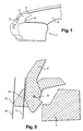
On connaît, par ailleurs, des projecteurs qui, au lieu d'être désolidarisés du véhicule, lors d'un choc frontal ou d'un choc piéton, se déplacent le long du véhicule. Un tel projecteur de véhicule est décrit dans le document EP-A-1-1 346 874. Un exemple de ce projecteur est représenté sur la figure 1. Plus précisément, la figure 1 représente l'avant d'un véhicule 1 équipé d'un projecteur 2. Ce projecteur 2 émet un faisceau lumineux dirigé essentiellement vers l'avant du véhicule 1, c'est-à-dire selon l'axe de la route. Ce projecteur 2 comporte un boîtier, non représenté sur la figure 1, fermé par une glace de protection 3 formant la face de sortie du projecteur 2. Le projecteur 2 comporte deux zones :
- une zone centrale 4 formant la partie la plus flexible du
projecteur 2 puisqu'elle comporte la glace de protection ; cette zone centrale 4 est aussi appelée zone frontale. - une zone latérale 5, entourant la zone frontale 4. Cette zone latérale 5 comporte une partie du boîtier.
- a
central zone 4 forming the most flexible part of theprojector 2 since it includes the protective glass; thiscentral zone 4 is also called frontal zone. - a
lateral zone 5 surrounding thefrontal zone 4. Thislateral zone 5 comprises a portion of the housing.
Le projecteur 2 comporte également des pattes de fixation, ou organes de liaison, assurant un déplacement du projecteur 2 vers l'arrière du véhicule 1, lors d'un choc frontal ou d'un choc piéton. Les organes de liaison comportent deux moyens de guidage différents assurant, respectivement, un coulissement du projecteur 2 vers l'arrière et vers le côté de l'aile 6 du véhicule 1. Le coulissement du projecteur 2 vers l'arrière du véhicule 1 et le coulissement du projecteur 2 vers le côté de l'aile 6 du véhicule 1 sont deux déplacements linéaires, combinés.The
Le déplacement du projecteur 2 vers le coté de l'aile 6 du véhicule 1 permet un dégagement du projecteur 2. Cependant, ce dégagement vers le coté de l'aile 6 du projecteur 2 provoque une collision du projecteur 2 contre le bord de l'aile 6 du véhicule. Le projecteur 2 termine alors son déplacement dans l'environnement moteur du véhicule. Autrement dit, le projecteur 2 s'écrase contre un ou plusieurs des éléments de l'environnement moteur du véhicule 1, créant ainsi de nombreux dégâts dans l'environnement moteur du véhicule 1, en plus de la démolition de l'aile 6 du véhicule 1.The displacement of the
Le déplacement du projecteur 2 vers l'arrière du véhicule 1 permet d'absorber une partie de l'énergie générée par le choc, car ce déplacement est limité par l'environnement moteur du véhicule. Cependant, cette absorption d'énergie n'est pas suffisante pour satisfaire à la nouvelle norme ; la protection du piéton n'est pas suffisamment assurée.Moving the
De plus, la cinématique de coulissement du projecteur 2 comporte, en cas de choc piéton, un risque important de blesser le piéton. En effet, lors d'un choc piéton, le coulissement du projecteur 1 vers l'arrière du véhicule propulse le piéton sur la zone latérale 5 du projecteur 2, qui est une zone rigide dudit projecteur, donc dangereuse pour le piéton.In addition, the sliding kinematics of the
L'invention a justement pour but de remédier aux inconvénients des techniques évoquées précédemment. A cette fin, l'invention propose un système de montage d'un projecteur sur un véhicule automobile, dans lequel, lors d'un choc piéton, le projecteur est déplacé en rotation autour d'un centre de rotation choisi. Le projecteur comporte un premier élément de liaison et le véhicule automobile comporte un second élément de liaison. Ces éléments de liaisons sont incurvés et adaptés l'un à l'autre pour assurer la rotation du projecteur lors d'un choc frontal ou d'un choc piéton.The purpose of the invention is precisely to overcome the disadvantages of the techniques mentioned above. To this end, the invention provides a mounting system of a projector on a motor vehicle, wherein, during a pedestrian impact, the projector is rotated around a selected center of rotation. The projector comprises a first connecting element and the motor vehicle comprises a second connecting element. These connecting elements are curved and adapted to each other to rotate the projector during a frontal impact or a pedestrian impact.
De façon plus précise, l'invention concerne un système de montage d'un projecteur sur un véhicule automobile, ce projecteur comportant un boîtier rigide fermé par une glace de protection, ledit système comportant :
- un premier élément de liaison fixé sur le projecteur,
- un second élément de liaison fixé sur le véhicule,
- le premier et le second éléments de liaison et étant assemblés de façon à glisser l'un dans l'autre,
- a first connection element fixed on the projector,
- a second connecting element fixed on the vehicle,
- the first and the second connecting elements and being assembled so as to slide into one another,
L'invention peut également comporter une ou plusieurs des caractéristiques suivantes :
- une position du centre de rotation du projecteur est déterminée en fonction d'une forme de la glace de protection du projecteur.
- la position du centre de rotation est déterminée en fonction d'une position optimale du projecteur à la fin de son déplacement.
- le centre de rotation du projecteur est centré sur le centre de gravité dudit projecteur.
- le premier élément de liaison est fixé sur une zone latérale du projecteur.
- le second élément de liaison forme un chemin de guidage et le premier élément de liaison est un élément guidé par le chemin de guidage.
- le chemin de guidage et l'élément guidé comportent au moins un moyen de freinage mécanique.
- le chemin de guidage a une forme crénelée et l'élément guidé a une forme en T, adaptée à s'insérer successivement entre des créneaux du chemin de guidage.
- le chemin de guidage a une forme effilée et l'élément guidé a une forme effilée, adaptée à s'insérer dans le chemin de guidage.
- le système de montage comporte une rampe de glissement du projecteur sous un bord tombé d'une aile du véhicule.
- la rampe est montée sur la glace de protection du projecteur.
- la rampe est fixée sur le boîtier du projecteur.
- une pièce est placée à une extrémité de la rampe.
- la rampe est facettée dans la glace de protection du projecteur.
- a position of the center of rotation of the projector is determined according to a shape of the protective glass of the projector.
- the position of the center of rotation is determined according to an optimal position of the projector at the end of its displacement.
- the center of rotation of the projector is centered on the center of gravity said projector.
- the first connecting element is fixed on a side area of the projector.
- the second connecting element forms a guide path and the first connecting element is an element guided by the guide path.
- the guide path and the guided element comprise at least one mechanical braking means.
- the guide path has a crenellated shape and the guided element has a T-shape, adapted to be inserted successively between crenellations of the guide path.
- the guide path has a tapered shape and the guided element has a tapered shape adapted to fit into the guide path.
- the mounting system includes a projector slip ramp under a fallen edge of a wing of the vehicle.
- the ramp is mounted on the protective glass of the projector.
- the ramp is attached to the projector housing.
- a piece is placed at one end of the ramp.
- the ramp is faceted in the protective glass of the projector.
L'invention concerne également un véhicule automobile comportant au moins un projecteur monté sur le véhicule automobile au moyen d'un système de montage selon l'invention.The invention also relates to a motor vehicle comprising at least one projector mounted on the motor vehicle by means of a mounting system according to the invention.
- La figure 1, déjà décrite, représente l'avant d'un véhicule automobile équipé d'un projecteur.Figure 1, already described, represents the front of a motor vehicle equipped with a projector.
-
La figure 2, la figure 3 et la figure 4 représentent schématiquement le système de l'invention à différentes phases de déplacement du projecteur 2.FIG. 2, FIG. 3 and FIG. 4 schematically represent the system of the invention at different phases of displacement of the
projector 2. - La figure 5 représente schématiquement un exemple d'une position du centre de rotation du projecteur.Figure 5 shows schematically an example of a position of the center of rotation of the projector.
- La figure 6 représente schématiquement une position du centre de rotation par rapport au centre de gravité du projecteur.Figure 6 shows schematically a position of the center of rotation with respect to the center of gravity of the projector.
- La figure 7 et la figure 8 représentent, respectivement, un premier et un second modes de réalisation des éléments de liaison de l'invention.Fig. 7 and Fig. 8 show, respectively, first and second embodiments of the connecting members of the invention.
- La figure 9, la figure 10 et la figure 11 représentent une rampe de glissement du projecteur sous un bord tombé de l'aile du véhicule.FIG. 9, FIG. 10 and FIG. 11 show a ramp of the projector under a fallen edge of the vehicle wing.
- La figure 12, la figure 13 et la figure 14 représentent, respectivement, un deuxième, un troisième et un quatrième modes de réalisation de la rampe de glissement.Figure 12, Figure 13 and Figure 14 show, respectively, a second, a third and a fourth embodiment of the slip ramp.
L'invention concerne un système de montage d'un projecteur sur un véhicule automobile permettant une rotation du projecteur par rapport au véhicule, lors d'une collision. Un exemple d'un système de montage, selon l'invention, est représenté sur la figure 2. Cette figure 2 montre un projecteur, un véhicule et le système de montage du projecteur sur le véhicule de façon très schématisé.The invention relates to a mounting system of a projector on a motor vehicle for a rotation of the projector relative to the vehicle, in a collision. An example of a mounting system according to the invention is shown in Figure 2. This Figure 2 shows a projector, a vehicle and the mounting system of the projector on the vehicle very schematically.
Pour mieux comprendre, tout au long de la description, la cinématique de rotation du projecteur, selon l'invention, le véhicule et le projecteur sont schématisés sur les figures 2 à 7, en deux blocs. Un premier bloc représente le véhicule 1 et un second bloc représente le projecteur 2. Le système de montage est représenté sur le second bloc, par mesure de simplification.To better understand, throughout the description, the rotational kinematics of the projector, according to the invention, the vehicle and the projector are shown schematically in Figures 2 to 7, in two blocks. A first block represents the
Le projecteur 2 est fixé au véhicule 1 par le système de montage de l'invention. Ce système de montage comporte deux éléments de liaison 7 et 8. Le premier élément de liaison 7 est monté sur le projecteur 2 dans la zone latérale 5 du projecteur. On appelle zone latérale, une zone du projecteur 2 comportant le boîtier rigide du projecteur 2. Le deuxième élément de liaison 8 est monté le véhicule 1, par exemple, sur le châssis du véhicule.The
Les éléments de liaisons 7 et 8 ont des structures adaptées pour coulisser l'une dans l'autre. L'élément de liaison 8 est un dispositif de guidage permettant de supporter et de guider l'élément de liaison 7. Il constitue un chemin de guidage, pour l'élément de liaison 7. L'élément de liaison 8 peut être, par exemple, un rail. L'élément de liaison 8 peut aussi être une coulisse ou toute autre structure permettant le coulissement de l'élément de liaison 7.The connecting
L'élément de liaison 7 est un élément guidé, adapté pour coulisser dans l'élément de liaison 8. Cet élément de liaison 7 peut être, par exemple, une glissière.The connecting
L'élément de liaison 7 et l'élément de liaison 8 peuvent être de longueur identique, comme montré sur la figure 2. L'élément de liaison 7, ou l'élément guidé 7, peut aussi avoir une longueur plus petite que l'élément de liaison 8, ou le rail 8.The connecting
Le rail 8 et l'élément guidé 7 ont une forme incurvée, ou circulaire, assurant un déplacement circulaire à l'élément guidé 7. Le rail 8 est fixé sur le véhicule 1 de sorte que le projecteur 2 est mobile par rapport au véhicule 1. Le déplacement de l'élément guidé 7, dans le rail 8, entraîne automatiquement un mouvement de rotation du projecteur 2.The
L'élément guidé 7 et le rail 8 sont montés au moins partiellement autour d'un centre de rotation 9 du projecteur 2. Ce centre de rotation 9 est défini par simulation et/ou expérimentation pour une rotation optimale du projecteur 2. En position normale, c'est-à-dire hors choc, le rail 8 et l'élément guidé 7 sont circonscrits, le rail 8 étant extérieur à l'élément guidé 7.The guided
Autrement dit, l'élément guidé 7 et le rail 8 forment des arcs de cercle montés autour du centre de rotation 9. Le centre de rotation 9 forme donc le centre de cercles passant par l'élément guidé 7 et le rail 8, la distance entre le centre de rotation 9 et le rail 8 étant supérieure à la distance entre le centre de rotation 9 et l'élément guidé 7.In other words, the guided
Dans une variante de l'invention, l'élément guidé 7 et le rail 8 sont fixés l'un à l'autre par des moyens de fixation détachables, c'est-à-dire aptes à se détacher ou se briser, en cas de choc. Ainsi, en fonctionnement normal, le projecteur 2 est immobile par rapport au véhicule 1. En cas de choc, les moyens de fixations se détachent, permettant le glissement de l'élément de liaison 7 dans le rail 8.In a variant of the invention, the guided
Les figures 2, 3 et 4 montrent la cinématique d'un véhicule 1 entrant en collision avec un impacteur 10. Cet impacteur 10 représente un piéton ou tout autre objet entrant en collision avec le véhicule 1 de manière frontale. Tout au long de la description, on considérera l'impacteur 10 comme étant un piéton, en sachant qu'il peut s'agir de tout autre obstacle frontal. L'impacteur 10 est représenté sur les figures 2, 3, 4 par un trait plein sensiblement inclinéFigures 2, 3 and 4 show the kinematics of a
Lors d'un choc frontal, l'impacteur 10 entre en contact avec une surface 11 de la zone latérale 5 du projecteur 2. L'intensité de la force de collision entre l'impacteur 10 et le projecteur 2 provoque la cassure des moyens de fixation de l'élément guidé 7 sur le rail 8, dans le cas où il existe de tels moyens de fixation.In the case of a frontal impact, the impactor 10 comes into contact with a
La force de collision, au moment de l'impact, entraîne un déplacement de l'élément guidé 7 sur le rail 8, comme montré sur la figure 3. Ce déplacement de l'élément guidé 7 sur le rail 8 entraîne le basculement du projecteur 2 par rapport au véhicule 1. Ce basculement du projecteur 2 correspond à un mouvement de rotation du projecteur 2 autour du centre de rotation 9. Ce mouvement rotatif est effectué suivant un sens de rotation 12 défini à la conception du projecteur 2.The collision force, at the moment of impact, causes the guided
La rotation du projecteur 2 a pour effet de déplacer la surface 11 d'impact de l'impacteur 10. Cette surface 11 se déplace vers la zone centrale 4, ou zone frontale, du projecteur 2, c'est-à-dire vers la zone la plus flexible du projecteur 2 puisqu'il s'agit du centre de la glace de protection 3. La surface d'impact 11 déplacée est nommée et référencée " surface d'impact 13 ". Cette rotation du projecteur 2 dégage ledit projecteur vers le côté de l'aile du véhicule 1 permettant ainsi au projecteur 2 de ne pas heurter l'environnement moteur du véhicule 1 au cours de sa rotation.The rotation of the
La position finale du projecteur 2 par rapport à l'impacteur 10 et au véhicule 1 à la fin du déplacement de l'élément guidé 7 sur le rail 8, est montré sur la figure 4. La fin du déplacement de l'élément guidé 7 sur le rail 8 entraîne la fin de la rotation du projecteur 2 autour du centre de rotation 9. Ce déplacement se termine lorsque l'élément guidé 7 atteint une butée sur le rail 8, ou lorsque l'élément guidé 7 sort du rail 8, comme montré sur la figure 4.The final position of the
En fin de rotation, la surface d'impact 13 se trouve sur la zone frontale 4 de la glace de protection 3. Cette surface 13 est la surface finale d'impact de l'impacteur 10 sur le projecteur 2. Cette surface finale 13 est une zone flexible du projecteur 2, donc une zone moins dangereuse pour le piéton, lorsqu'il s'agit d'un choc piéton.At the end of rotation, the
En outre, la rotation du projecteur 2 absorbe une partie de l'énergie générée par la collision entre l'impacteur 10 et le véhicule 1. Cette absorption d'énergie a pour effet de diminuer de manière sensible l'énergie reçue par l'impacteur 10, en particulier, lorsque l'impacteur 10 représente un piéton. La sécurité du piéton s'en trouve améliorée. Par ailleurs, cette rotation du projecteur 2 permet que le projecteur n'entre pas, avec toute la force du choc, dans le véhicule 1. Le moteur du véhicule 1, qui est l'un des éléments les plus chers du véhicule 1, ainsi que l'environnement moteur, se trouvent ainsi protégés. Les dégâts du véhicule 1 sont donc limités et les coûts de réparation du véhicule 1 sont considérablement diminués.In addition, the rotation of the
Comme expliqué précédemment, la rotation du projecteur 2 est établie autour du centre de rotation 9. Ce centre de rotation 9 est défini en fonction de la position finale optimale du projecteur 2 par rapport à l'impacteur 10. Autrement dit, la position du centre de rotation 9 est prédéfinie pour chaque projecteur en fonction, notamment, de la position normale du projecteur 2 sur le véhicule 1 et de la position finale voulue après rotation. Des exemples de définition du centre de rotation 9 sont montrés sur les figures 5 et 6.As explained above, the rotation of the
La figure 5 montre le centre de rotation 9 du projecteur 2 par rapport à différentes positions de l'impacteur 10. Le centre de rotation 9 est déterminé à la conception du projecteur 2, il peut être choisi en tout point du projecteur 2. Le choix du centre de rotation 9 est, de préférence, réalisé par simulation et optimisation. Il est défini en tenant compte de la forme du projecteur 2 et de celle du véhicule 1. Il est défini aussi en fonction d'une position initiale du projecteur 2 et d'une position finale optimale du projecteur sur l'impacteur 10. La position initiale est la position dans laquelle se trouve le projecteur 2, en fonctionnement normal. Dans l'exemple de la figure 5, la zone d'impact 15 est choisie comme position initiale. La position finale correspond à la position du projecteur 2 contre l'impacteur 10, en fin de choc. De préférence, on choisit comme position finale la zone frontale 4 du projecteur 2. La position finale est représentée, sur la figure 5, par la surface d'impact 16.FIG. 5 shows the center of
Le centre de rotation 9 peut aussi être mobile. Dans ce cas, la position du centre de rotation 9 dépend de l'intensité de la force de collision entre le véhicule 1 et l'impacteur 10 ainsi que des positions initiale et finale du projecteur 2 par rapport à l'impacteur 10.The center of
Dans une variante, le centre de rotation 9 est centré sur le centre de gravité du projecteur 2, entraînant la transformation de l'énergie de translation en énergie de rotation de façon optimale.In a variant, the center of
Dans une autre variante, le centre de rotation 9 est différent du centre de gravité, comme montré sur la figure 6. En effet, la figure 6 montre une position optimale du centre de rotation 9, dans le cas où le centre de rotation 9 n'est pas le centre de gravité 17 du projecteur 2.In another variant, the center of
Le centre de rotation 9 est choisi de façon à être aligné avec le centre de gravité 17. Cet alignement est représenté par une droite 19. Cette droite 19 est, de préférence, parallèle à l'impacteur 10 en position initiale et à l'impacteur 10 en position finale. Elle est perpendiculaire à la force d'impact 18, représentative de l'énergie générée lors du choc entre le véhicule 1 et l'impacteur 10. Le centre de rotation 9 peut être n'importe quel point de la droite 19. Le centre de rotation 9 est aussi choisi en fonction de la distance entre la force d'impact 18 et le centre de rotation 9 et la distance entre le centre de gravité 17 et le centre de rotation 9. La rotation du projecteur 2 est optimisée lorsque la distance de la force d'impact 18 au centre de rotation 9 est supérieure à la distance du centre de gravité 17 au centre de rotation 9.The center of
Comme expliqué précédemment, la rotation du projecteur 2 entraîne une absorption, par le projecteur, d'une partie de l'énergie générée par la collision du véhicule 1 avec l'impacteur 10. Autrement dit, une partie de l'énergie générée par la collision est dissipée dans le projecteur 2 en rotation. Pour augmenter encore cette dissipation d'énergie, l'élément guidé 7 et le rail 8 comportent des structures de freinage mécanique. Ces structures de freinage mécanique permettent de ralentir le mouvement de rotation du projecteur 2, absorbant ainsi une partie de l'énergie de la collision.As explained above, the rotation of the
La figure 7 montre un premier mode de réalisation de ce système de freinage. Dans ce mode de réalisation, le rail 8 comporte deux barres de structures 20 et 21 rectilignes, non parallèles, susceptibles de former à leurs extrémités 20e et 21e un angle non droit. Le rail 8 a donc une forme effilée. L'élément guidé 7 comporte une pièce 22 effilée, dont la forme est adaptée pour s'insérer entre les barres 20 et 21 du rail 8. La pièce 22 de l'élément guidé 7 a une largeur dégressive d'une extrémité 23 à une extrémité 24.Figure 7 shows a first embodiment of this braking system. In this embodiment, the
Dans ce système de freinage, les barres 20 et 21 du rail 8 reçoivent la pièce 22 de l'élément guidé 7. Dans une variante, l'élément guidé 7 et le rail 8 sont réalisés dans des matériaux flexibles. Ces matériaux flexibles ont la propriété de reprendre, partiellement ou totalement, leur forme et leur volume, après les avoir perdus par compression ou par extension. La pièce 22 de l'élément guidé 7 constitue alors une membrane déformable qui transmet aux barres 20 et 21 du rail 8, la force d'impact reçue par le véhicule 1 lors de la collision avec l'impacteur 10. La forme effilée du rail 8 ralentit le déplacement de l'élément guidé 7 sur le rail 8, entraînant un ralentissement du mouvement de rotation du projecteur 2.In this braking system, the
Un autre mode de réalisation du système de freinage est montré sur la figure 8. Dans ce mode de réalisation, le rail 8 a une forme crénelée, c'est-à-dire qu'il comporte plusieurs créneaux 27. L'élément guidé 7 a une forme en T destinée à s'enchâsser sur le rail 8. Pour cela, l'élément guidé 7 comporte une branche 28 et une branche 29, perpendiculaire à la branche 28. La branche 29 a une longueur adaptée à la hauteur des créneaux 27 du rail 8.Another embodiment of the braking system is shown in FIG. 8. In this embodiment, the
Lors de la collision du véhicule 1 avec l'impacteur 10, l'élément guidé 7 se déplace sur le rail 8 par ruptures successives. Autrement dit, sous l'effet de la force d'impact, la branche 29 saute d'un créneau 27 à un autre créneau, chaque saut absorbant un peu d'énergie.During the collision of the
Le déplacement de l'élément guidé 7 sur le rail 8, par ruptures successives, provoque donc le ralentissement du mouvement de rotation du projecteur 2.The displacement of the guided
Dans un mode de réalisation de l'invention, une rampe de glissement est prévue pour assurer le dégagement du projecteur 2 vers l'aile 6 du véhicule 1, sans détériorer l'aile ni la doublure de cette aile. Ce mode de réalisation est représenté sur les figures 9 à 11 montrant la cinématique du système lors d'une collision.In one embodiment of the invention, a sliding ramp is provided to ensure the release of the
Plus précisément, la figure 9 représente l'aile 6 du véhicule et un exemple de projecteur 2 équipé d'une rampe 36 de glissement. Comme la plupart des projecteurs actuels, le projecteur 2 comporte une barre 30 rigide, par exemple en métal. Cette barre 30 comporte à son extrémité une pièce 31 en forme de U, comportant une jambe 32 et une jambe 33. La jambe 33 est située entre la glace de protection 3 et la barre 30. La jambe 32 est située dans l'environnement moteur du véhicule. La glace de protection 3 est généralement encastrée dans l'espace formé par les jambes 32 et 33.More precisely, FIG. 9 represents the
L'aile 6 du véhicule comporte une extrémité 35 emboutie en forme de L. Cette extrémité constitue le bord tombé de l'aile. En position normale du projecteur 2, l'extrémité 35 est écartée de la jambe 32.The
Lors de la collision du véhicule avec l'impacteur, le projecteur 2, par un mouvement de rotation décrit précédemment, est dégagé vers le côté de l'aile 6 du véhicule. Lors de la rotation dudit projecteur, la jambe 32 peut heurter le bord tombé 35 de l'aile 6 du véhicule, entraînant alors la déformation de l'aile 6.In the collision of the vehicle with the impactor, the
La rampe 36 de glissement de l'invention, réalisée par exemple en matériau plastique, permet de faire glisser la jambe 32 sous le bord tombé 35 de l'aile 6. Pour cela, la rampe 36 est fixée dans la zone latérale 5 du projecteur 2, sur la jambe 32 de la pièce 31. La rampe 36 forme un plan incliné, entre, extrémité 37 et une extrémité 38, permettant à ladite rampe de glisser sous le bord tombé 35 de l'aile 6.The sliding
La forme inclinée de la rampe 36 impose le sens de déplacement du projecteur 2 sous le bord tombé 35 de l'aile 6, comme le montre la figure 10. La rotation du projecteur 2 provoque le contact de l'extrémité 37 de la rampe 36 avec le bord tombé 35 de l'aile 6. L'extrémité 37 est adaptée pour s'insérer sous le bord tombé 35, de sorte que la rampe 36 glisse sous ledit bord tombé 35, évitant tout heurt entre le bord tombé 35 et la jambe 32.The inclined shape of the
La figure 11 montre le projecteur 2 à la fin de son déplacement sous le bord tombé 35 de l'aile 6. L'inclinaison de la rampe 36 a permis le glissement de la jambe 32 sous le bord tombé 35 de l'aile 6. Il y a donc, entre la jambe 32 et le bord tombé 35 de l'aile 6, un espace de protection comportant la rampe 36. Ainsi, lors d'une collision, la jambe 32 de la pièce 31 ne heurte pas le bord tombé 35 de l'aile 6 quel que soit le type de projecteur.FIG. 11 shows the
Dans une seconde variante, représentée sur la figure 12, une pièce 39 est fixée sur la glace de protection 3. Cette pièce 39, par exemple réalisée dans un matériau plastique, est fixée à l'extrémité 37 de la rampe 36, par exemple, par surmoulage. Cette pièce 39 forme une lame de ressort, située au pied de la rampe 36. Ainsi, en position normale le bord tombé 35 de l'aile 6 est en appui sur la pièce 39, comprimant ladite pièce 39. Cette compression de la pièce 39 permet au bord tombé 35 d'être placé sur le même niveau que l'extrémité 37 de la rampe 36. Lors du glissement de la pièce 39 sous le bord tombé 35 de l'aile 6, la pièce 39 se décompresse.In a second variant, shown in FIG. 12, a
La figure 13 montre une troisième variante de la rampe 36. Dans cette variante, une bosse 40 est fixée sur la glace de protection 3. Cette bosse 40 est située entre la jambe 32 de la pièce 31 et le bord tombé 35 de l'aile 6. La bosse 40 est formée par un plan incliné de même niveau que la jambe 32. Ainsi, lorsque la jambe a glissé sous le bord tombé 35, ledit bord tombé est en appui sur ladite jambe 32. La bosse 40 remplit les mêmes fonctions que la rampe 36.FIG. 13 shows a third variant of the
La figure 14 montre une quatrième variante de la rampe 36. Dans cette variante, la glace de protection 3 a une forme spécifique en forme de rampe. Dans ce cas, la glace 3 est facettée afin de former une rampe. Dans ce mode de réalisation, c'est la glace 3 elle-même qui constitue la rampe. Cette variant a l'avantage de ne pas nécessiter d'opération de fabrication supplémentaire, la rampe étant réalisée en même temps que la glace de protection.FIG. 14 shows a fourth variant of the
Quelle que soit la variante, la rampe 36 aide au dégagement du projecteur 2 du coté de l'aile 6 lors d'un choc avec un impacteur. Qu'elle soit ajoutée ou réalisée par la modification de la forme de la glace de protection 3, la rampe 36 provoque la déportation du projecteur 2 évitant ainsi à l'aile 6 d'être endommagée.Whatever the variant, the
Claims (15)
Applications Claiming Priority (1)
| Application Number | Priority Date | Filing Date | Title |
|---|---|---|---|
| FR0410507A FR2876067B1 (en) | 2004-10-05 | 2004-10-05 | SYSTEM FOR MOUNTING A PROJECTOR ON A MOTOR VEHICLE AND MOTOR VEHICLE COMPRISING SUCH A SYSTEM |
Publications (2)
| Publication Number | Publication Date |
|---|---|
| EP1645465A1 true EP1645465A1 (en) | 2006-04-12 |
| EP1645465B1 EP1645465B1 (en) | 2007-03-28 |
Family
ID=34951893
Family Applications (1)
| Application Number | Title | Priority Date | Filing Date |
|---|---|---|---|
| EP05292044A Not-in-force EP1645465B1 (en) | 2004-10-05 | 2005-09-30 | System for mounting a headlamp in a vehicle and vehicle with such a mounting system |
Country Status (6)
| Country | Link |
|---|---|
| US (1) | US7946745B2 (en) |
| EP (1) | EP1645465B1 (en) |
| AT (1) | ATE358037T1 (en) |
| DE (1) | DE602005000774T2 (en) |
| ES (1) | ES2284142T3 (en) |
| FR (1) | FR2876067B1 (en) |
Cited By (3)
| Publication number | Priority date | Publication date | Assignee | Title |
|---|---|---|---|---|
| EP2782780A1 (en) * | 2011-11-24 | 2014-10-01 | Renault S.A.S. | Assembly of a headlight and a device for mounting same, which reduces the amount of repairs to the adjacent fender upon an impact, and related vehicle |
| WO2017093523A1 (en) * | 2015-12-03 | 2017-06-08 | Hella Kgaa Hueck & Co. | Arrangement of a headlight in a vehicle having damage protection for the event of a crash |
| EP3501894A1 (en) * | 2017-12-19 | 2019-06-26 | Ningbo Geely Automobile Research & Development Co., Ltd. | A device for suspension of a lamp in a vehicle |
Families Citing this family (6)
| Publication number | Priority date | Publication date | Assignee | Title |
|---|---|---|---|---|
| US9033399B2 (en) * | 2010-03-01 | 2015-05-19 | Sabic Global Technologies B.V. | Energy absorber elements and vehicle systems |
| DE102011115797A1 (en) * | 2011-10-11 | 2013-04-11 | Gm Global Technology Operations, Llc | Headlamp assembly of a vehicle with headlamp fixture |
| DE102011122450A1 (en) | 2011-12-22 | 2013-06-27 | Daimler Ag | Retaining arrangement of a lighting device and a fender on a motor vehicle |
| EP2900518A1 (en) * | 2012-09-25 | 2015-08-05 | Jaguar Land Rover Limited | Mounting bracket and method of supporting a structure |
| US20170259678A1 (en) * | 2016-03-08 | 2017-09-14 | Faraday&Future Inc. | Electric vehicle charge port |
| DE102019212395A1 (en) * | 2019-08-19 | 2021-02-25 | Volkswagen Aktiengesellschaft | Fastening arrangement for a lighting device of a motor vehicle |
Citations (6)
| Publication number | Priority date | Publication date | Assignee | Title |
|---|---|---|---|---|
| EP0422405A1 (en) * | 1989-10-13 | 1991-04-17 | IVECO FIAT S.p.A. | Vehicle bodywork component incorporating a lighting device |
| EP0933253A2 (en) * | 1998-02-03 | 1999-08-04 | MAGNETI MARELLI S.p.A. | A device for positioning and securing a headlamp on a support structure of a vehicle |
| DE19955648A1 (en) * | 1999-11-19 | 2000-05-25 | Audi Ag | Headlamp arrangement for motor vehicle has vertical pivot axis and panel curved or inclined wrt. vehicle's central pane so impact on headlamp turns it towards interior of vehicle |
| EP1024075A1 (en) * | 1999-01-26 | 2000-08-02 | MAGNETI MARELLI CLIMATIZZAZIONE S.p.A. | Preassembled frontal assembly for vehicles |
| EP1103417A1 (en) * | 1999-11-29 | 2001-05-30 | Valeo Vision | Mobile lighting or signaling device for vehicle |
| EP1346874A1 (en) | 2002-03-19 | 2003-09-24 | Peugeot Citroen Automobiles S.A. | Mounting a lighting unit on vehicle bodypart |
Family Cites Families (7)
| Publication number | Priority date | Publication date | Assignee | Title |
|---|---|---|---|---|
| US2254790A (en) * | 1940-07-30 | 1941-09-02 | Crowe Name Plate & Mfg Co | Lamp bracket |
| US3646339A (en) * | 1969-06-24 | 1972-02-29 | Schoeman Y G P | Pivoting devices allowing continuous automatic headlamp adjusting |
| DE2542920C3 (en) * | 1975-09-26 | 1979-10-25 | Dr.Ing.H.C. F. Porsche Ag, 7000 Stuttgart | Bumpers for vehicles, in particular motor vehicles |
| DE3728752C1 (en) * | 1987-08-28 | 1988-12-15 | Daimler Benz Ag | Headlights for motor vehicles |
| US4947295A (en) * | 1989-03-06 | 1990-08-07 | General Motors Corporation | Actuator mechanism for a headlamp cover |
| US5635899A (en) * | 1994-10-17 | 1997-06-03 | Winner International Royalty Corporation | Vehicle anti-theft device and system |
| US7252419B1 (en) * | 2003-12-09 | 2007-08-07 | Honda Motor Co., Ltd. | Motorcycle headlight assembly |
-
2004
- 2004-10-05 FR FR0410507A patent/FR2876067B1/en not_active Expired - Fee Related
-
2005
- 2005-09-30 DE DE602005000774T patent/DE602005000774T2/en active Active
- 2005-09-30 ES ES05292044T patent/ES2284142T3/en active Active
- 2005-09-30 AT AT05292044T patent/ATE358037T1/en not_active IP Right Cessation
- 2005-09-30 EP EP05292044A patent/EP1645465B1/en not_active Not-in-force
- 2005-10-05 US US11/244,501 patent/US7946745B2/en not_active Expired - Fee Related
Patent Citations (6)
| Publication number | Priority date | Publication date | Assignee | Title |
|---|---|---|---|---|
| EP0422405A1 (en) * | 1989-10-13 | 1991-04-17 | IVECO FIAT S.p.A. | Vehicle bodywork component incorporating a lighting device |
| EP0933253A2 (en) * | 1998-02-03 | 1999-08-04 | MAGNETI MARELLI S.p.A. | A device for positioning and securing a headlamp on a support structure of a vehicle |
| EP1024075A1 (en) * | 1999-01-26 | 2000-08-02 | MAGNETI MARELLI CLIMATIZZAZIONE S.p.A. | Preassembled frontal assembly for vehicles |
| DE19955648A1 (en) * | 1999-11-19 | 2000-05-25 | Audi Ag | Headlamp arrangement for motor vehicle has vertical pivot axis and panel curved or inclined wrt. vehicle's central pane so impact on headlamp turns it towards interior of vehicle |
| EP1103417A1 (en) * | 1999-11-29 | 2001-05-30 | Valeo Vision | Mobile lighting or signaling device for vehicle |
| EP1346874A1 (en) | 2002-03-19 | 2003-09-24 | Peugeot Citroen Automobiles S.A. | Mounting a lighting unit on vehicle bodypart |
Cited By (5)
| Publication number | Priority date | Publication date | Assignee | Title |
|---|---|---|---|---|
| EP2782780A1 (en) * | 2011-11-24 | 2014-10-01 | Renault S.A.S. | Assembly of a headlight and a device for mounting same, which reduces the amount of repairs to the adjacent fender upon an impact, and related vehicle |
| WO2017093523A1 (en) * | 2015-12-03 | 2017-06-08 | Hella Kgaa Hueck & Co. | Arrangement of a headlight in a vehicle having damage protection for the event of a crash |
| US10788187B2 (en) | 2015-12-03 | 2020-09-29 | HELLA GmbH & Co. KGaA | Arrangement of a headlight in a vehicle having damage protection for the event of a crash |
| EP3501894A1 (en) * | 2017-12-19 | 2019-06-26 | Ningbo Geely Automobile Research & Development Co., Ltd. | A device for suspension of a lamp in a vehicle |
| US11077785B2 (en) | 2017-12-19 | 2021-08-03 | Ningbo Geely Automobile Research & Development Co. | Device for suspension of a lamp in a vehicle |
Also Published As
| Publication number | Publication date |
|---|---|
| US7946745B2 (en) | 2011-05-24 |
| FR2876067A1 (en) | 2006-04-07 |
| DE602005000774T2 (en) | 2008-01-24 |
| EP1645465B1 (en) | 2007-03-28 |
| DE602005000774D1 (en) | 2007-05-10 |
| FR2876067B1 (en) | 2008-02-01 |
| ES2284142T3 (en) | 2007-11-01 |
| US20060072333A1 (en) | 2006-04-06 |
| ATE358037T1 (en) | 2007-04-15 |
Similar Documents
| Publication | Publication Date | Title |
|---|---|---|
| EP1645465B1 (en) | System for mounting a headlamp in a vehicle and vehicle with such a mounting system | |
| EP3554927B1 (en) | Aerodynamic deflector device for motor vehicle wheel | |
| EP1645799A1 (en) | Energy absorbing headlamp for vehicles and process for absorbing energy caused by an impact with a pedestrian | |
| EP3390209B1 (en) | Aerodynamic deflector device for motor vehicle wheel | |
| WO2006136671A1 (en) | Guided low area for the front of a motor vehicle | |
| EP2186686A1 (en) | Shifting device for rigid element and vehicle equipped therewith | |
| WO2019063730A1 (en) | Motor vehicle deflector device | |
| EP1733927A1 (en) | Energy absorption beam, especially for a motor vehicle bumper beam and motor vehicle with such a beam | |
| WO2017153662A1 (en) | Wheel deflector device and corresponding front-end module | |
| WO2007066035A1 (en) | Fastening system for a cooling module and a vehicle provided therewith | |
| FR2928318A1 (en) | Energy absorbing assembly for bumper of motor vehicle during e.g. pedestrian impact, has pin that occupies deployed and folded position, and locking device controlled for being displaced between active and inactive positions | |
| FR3081820A1 (en) | REAR MOBILE VEHICLE DIFFUSER WITH RETRACTABLE PANEL | |
| EP1601558B1 (en) | Impact protection device for a front face of a motor vehicle | |
| FR2917026A1 (en) | ENERGY ABSORPTION ASSEMBLY COMPRISING AN ANTI-RETURN DEVICE | |
| FR2895955A1 (en) | Energy absorbing device for motor vehicle, has beam pivoting on chassis of vehicle around longitudinal axis of beam between two positions, where beam presents low and high stiffness when in respective positions | |
| EP0588719B1 (en) | Tiltable bumper for vehicles | |
| EP3344485B1 (en) | Device for sealing a front-end air intake of a motor vehicle and front-end module for a motor vehicle | |
| EP1750972B1 (en) | Improved motor vehicle headlight | |
| FR3061882A1 (en) | FRONT OPTICAL BLOCK MOUNT ADAPTED TO CUT THE TRACK OF THE OPTICAL BLOCK DURING A FRONT SHOCK OF A VEHICLE | |
| EP2080666B1 (en) | Front block of an automobile with self-centring headlight | |
| FR2833222A1 (en) | Protection device for pedestrians in event of front collision with automobile comprises arm extending bonnet rear, which rotates on vehicle structure, connected by electrically controlled fixings | |
| EP2243662A1 (en) | Lighting and/or signalling device for a vehicle | |
| EP2042389A1 (en) | System for protecting pedestrians in the event of vehicle crash | |
| FR2933040A1 (en) | Bump arrangement for motor vehicle, has cooling module received in structural body element by protection assembly, where assembly allows limited movement of module towards drive train along determined distance during impact | |
| FR3131717A1 (en) | Headlight housing for a motor vehicle provided with a guide ramp |
Legal Events
| Date | Code | Title | Description |
|---|---|---|---|
| PUAI | Public reference made under article 153(3) epc to a published international application that has entered the european phase |
Free format text: ORIGINAL CODE: 0009012 |
|
| AK | Designated contracting states |
Kind code of ref document: A1 Designated state(s): AT BE BG CH CY CZ DE DK EE ES FI FR GB GR HU IE IS IT LI LT LU LV MC NL PL PT RO SE SI SK TR |
|
| AX | Request for extension of the european patent |
Extension state: AL BA HR MK YU |
|
| 17P | Request for examination filed |
Effective date: 20060901 |
|
| GRAP | Despatch of communication of intention to grant a patent |
Free format text: ORIGINAL CODE: EPIDOSNIGR1 |
|
| AKX | Designation fees paid |
Designated state(s): AT BE BG CH CY CZ DE DK EE ES FI FR GB GR HU IE IS IT LI LT LU LV MC NL PL PT RO SE SI SK TR |
|
| GRAS | Grant fee paid |
Free format text: ORIGINAL CODE: EPIDOSNIGR3 |
|
| GRAA | (expected) grant |
Free format text: ORIGINAL CODE: 0009210 |
|
| AK | Designated contracting states |
Kind code of ref document: B1 Designated state(s): AT BE BG CH CY CZ DE DK EE ES FI FR GB GR HU IE IS IT LI LT LU LV MC NL PL PT RO SE SI SK TR |
|
| PG25 | Lapsed in a contracting state [announced via postgrant information from national office to epo] |
Ref country code: NL Free format text: LAPSE BECAUSE OF FAILURE TO SUBMIT A TRANSLATION OF THE DESCRIPTION OR TO PAY THE FEE WITHIN THE PRESCRIBED TIME-LIMIT Effective date: 20070328 Ref country code: PL Free format text: LAPSE BECAUSE OF FAILURE TO SUBMIT A TRANSLATION OF THE DESCRIPTION OR TO PAY THE FEE WITHIN THE PRESCRIBED TIME-LIMIT Effective date: 20070328 Ref country code: AT Free format text: LAPSE BECAUSE OF FAILURE TO SUBMIT A TRANSLATION OF THE DESCRIPTION OR TO PAY THE FEE WITHIN THE PRESCRIBED TIME-LIMIT Effective date: 20070328 Ref country code: FI Free format text: LAPSE BECAUSE OF FAILURE TO SUBMIT A TRANSLATION OF THE DESCRIPTION OR TO PAY THE FEE WITHIN THE PRESCRIBED TIME-LIMIT Effective date: 20070328 Ref country code: SI Free format text: LAPSE BECAUSE OF FAILURE TO SUBMIT A TRANSLATION OF THE DESCRIPTION OR TO PAY THE FEE WITHIN THE PRESCRIBED TIME-LIMIT Effective date: 20070328 |
|
| REG | Reference to a national code |
Ref country code: GB Ref legal event code: FG4D Free format text: NOT ENGLISH |
|
| REG | Reference to a national code |
Ref country code: CH Ref legal event code: EP |
|
| REF | Corresponds to: |
Ref document number: 602005000774 Country of ref document: DE Date of ref document: 20070510 Kind code of ref document: P |
|
| REG | Reference to a national code |
Ref country code: IE Ref legal event code: FG4D Free format text: LANGUAGE OF EP DOCUMENT: FRENCH |
|
| PG25 | Lapsed in a contracting state [announced via postgrant information from national office to epo] |
Ref country code: SE Free format text: LAPSE BECAUSE OF FAILURE TO SUBMIT A TRANSLATION OF THE DESCRIPTION OR TO PAY THE FEE WITHIN THE PRESCRIBED TIME-LIMIT Effective date: 20070628 |
|
| PG25 | Lapsed in a contracting state [announced via postgrant information from national office to epo] |
Ref country code: IS Free format text: LAPSE BECAUSE OF FAILURE TO SUBMIT A TRANSLATION OF THE DESCRIPTION OR TO PAY THE FEE WITHIN THE PRESCRIBED TIME-LIMIT Effective date: 20070728 |
|
| PG25 | Lapsed in a contracting state [announced via postgrant information from national office to epo] |
Ref country code: PT Free format text: LAPSE BECAUSE OF FAILURE TO SUBMIT A TRANSLATION OF THE DESCRIPTION OR TO PAY THE FEE WITHIN THE PRESCRIBED TIME-LIMIT Effective date: 20070828 |
|
| NLV1 | Nl: lapsed or annulled due to failure to fulfill the requirements of art. 29p and 29m of the patents act | ||
| GBV | Gb: ep patent (uk) treated as always having been void in accordance with gb section 77(7)/1977 [no translation filed] |
Effective date: 20070328 |
|
| REG | Reference to a national code |
Ref country code: ES Ref legal event code: FG2A Ref document number: 2284142 Country of ref document: ES Kind code of ref document: T3 |
|
| PG25 | Lapsed in a contracting state [announced via postgrant information from national office to epo] |
Ref country code: SK Free format text: LAPSE BECAUSE OF FAILURE TO SUBMIT A TRANSLATION OF THE DESCRIPTION OR TO PAY THE FEE WITHIN THE PRESCRIBED TIME-LIMIT Effective date: 20070328 |
|
| REG | Reference to a national code |
Ref country code: IE Ref legal event code: FD4D |
|
| PG25 | Lapsed in a contracting state [announced via postgrant information from national office to epo] |
Ref country code: CZ Free format text: LAPSE BECAUSE OF FAILURE TO SUBMIT A TRANSLATION OF THE DESCRIPTION OR TO PAY THE FEE WITHIN THE PRESCRIBED TIME-LIMIT Effective date: 20070328 Ref country code: RO Free format text: LAPSE BECAUSE OF FAILURE TO SUBMIT A TRANSLATION OF THE DESCRIPTION OR TO PAY THE FEE WITHIN THE PRESCRIBED TIME-LIMIT Effective date: 20070328 |
|
| PG25 | Lapsed in a contracting state [announced via postgrant information from national office to epo] |
Ref country code: DK Free format text: LAPSE BECAUSE OF FAILURE TO SUBMIT A TRANSLATION OF THE DESCRIPTION OR TO PAY THE FEE WITHIN THE PRESCRIBED TIME-LIMIT Effective date: 20070328 Ref country code: LV Free format text: LAPSE BECAUSE OF FAILURE TO SUBMIT A TRANSLATION OF THE DESCRIPTION OR TO PAY THE FEE WITHIN THE PRESCRIBED TIME-LIMIT Effective date: 20070328 Ref country code: IE Free format text: LAPSE BECAUSE OF FAILURE TO SUBMIT A TRANSLATION OF THE DESCRIPTION OR TO PAY THE FEE WITHIN THE PRESCRIBED TIME-LIMIT Effective date: 20070328 |
|
| PLBE | No opposition filed within time limit |
Free format text: ORIGINAL CODE: 0009261 |
|
| STAA | Information on the status of an ep patent application or granted ep patent |
Free format text: STATUS: NO OPPOSITION FILED WITHIN TIME LIMIT |
|
| PG25 | Lapsed in a contracting state [announced via postgrant information from national office to epo] |
Ref country code: LT Free format text: LAPSE BECAUSE OF FAILURE TO SUBMIT A TRANSLATION OF THE DESCRIPTION OR TO PAY THE FEE WITHIN THE PRESCRIBED TIME-LIMIT Effective date: 20070328 |
|
| 26N | No opposition filed |
Effective date: 20080102 |
|
| BERE | Be: lapsed |
Owner name: VALEO VISION Effective date: 20070930 |
|
| PG25 | Lapsed in a contracting state [announced via postgrant information from national office to epo] |
Ref country code: MC Free format text: LAPSE BECAUSE OF NON-PAYMENT OF DUE FEES Effective date: 20070930 Ref country code: GR Free format text: LAPSE BECAUSE OF FAILURE TO SUBMIT A TRANSLATION OF THE DESCRIPTION OR TO PAY THE FEE WITHIN THE PRESCRIBED TIME-LIMIT Effective date: 20070629 Ref country code: GB Free format text: LAPSE BECAUSE OF FAILURE TO SUBMIT A TRANSLATION OF THE DESCRIPTION OR TO PAY THE FEE WITHIN THE PRESCRIBED TIME-LIMIT Effective date: 20070328 |
|
| PG25 | Lapsed in a contracting state [announced via postgrant information from national office to epo] |
Ref country code: BE Free format text: LAPSE BECAUSE OF NON-PAYMENT OF DUE FEES Effective date: 20070930 |
|
| PG25 | Lapsed in a contracting state [announced via postgrant information from national office to epo] |
Ref country code: EE Free format text: LAPSE BECAUSE OF FAILURE TO SUBMIT A TRANSLATION OF THE DESCRIPTION OR TO PAY THE FEE WITHIN THE PRESCRIBED TIME-LIMIT Effective date: 20070328 |
|
| PG25 | Lapsed in a contracting state [announced via postgrant information from national office to epo] |
Ref country code: CY Free format text: LAPSE BECAUSE OF FAILURE TO SUBMIT A TRANSLATION OF THE DESCRIPTION OR TO PAY THE FEE WITHIN THE PRESCRIBED TIME-LIMIT Effective date: 20070328 |
|
| PG25 | Lapsed in a contracting state [announced via postgrant information from national office to epo] |
Ref country code: LU Free format text: LAPSE BECAUSE OF NON-PAYMENT OF DUE FEES Effective date: 20070930 Ref country code: BG Free format text: LAPSE BECAUSE OF FAILURE TO SUBMIT A TRANSLATION OF THE DESCRIPTION OR TO PAY THE FEE WITHIN THE PRESCRIBED TIME-LIMIT Effective date: 20070628 |
|
| PG25 | Lapsed in a contracting state [announced via postgrant information from national office to epo] |
Ref country code: TR Free format text: LAPSE BECAUSE OF FAILURE TO SUBMIT A TRANSLATION OF THE DESCRIPTION OR TO PAY THE FEE WITHIN THE PRESCRIBED TIME-LIMIT Effective date: 20070328 Ref country code: HU Free format text: LAPSE BECAUSE OF FAILURE TO SUBMIT A TRANSLATION OF THE DESCRIPTION OR TO PAY THE FEE WITHIN THE PRESCRIBED TIME-LIMIT Effective date: 20070929 |
|
| REG | Reference to a national code |
Ref country code: CH Ref legal event code: PL |
|
| PG25 | Lapsed in a contracting state [announced via postgrant information from national office to epo] |
Ref country code: CH Free format text: LAPSE BECAUSE OF NON-PAYMENT OF DUE FEES Effective date: 20090930 Ref country code: LI Free format text: LAPSE BECAUSE OF NON-PAYMENT OF DUE FEES Effective date: 20090930 |
|
| REG | Reference to a national code |
Ref country code: FR Ref legal event code: PLFP Year of fee payment: 12 |
|
| REG | Reference to a national code |
Ref country code: FR Ref legal event code: PLFP Year of fee payment: 13 |
|
| REG | Reference to a national code |
Ref country code: FR Ref legal event code: PLFP Year of fee payment: 14 |
|
| PGFP | Annual fee paid to national office [announced via postgrant information from national office to epo] |
Ref country code: IT Payment date: 20180907 Year of fee payment: 14 Ref country code: FR Payment date: 20180928 Year of fee payment: 14 Ref country code: DE Payment date: 20180913 Year of fee payment: 14 |
|
| PGFP | Annual fee paid to national office [announced via postgrant information from national office to epo] |
Ref country code: ES Payment date: 20181023 Year of fee payment: 14 |
|
| REG | Reference to a national code |
Ref country code: DE Ref legal event code: R119 Ref document number: 602005000774 Country of ref document: DE |
|
| PG25 | Lapsed in a contracting state [announced via postgrant information from national office to epo] |
Ref country code: DE Free format text: LAPSE BECAUSE OF NON-PAYMENT OF DUE FEES Effective date: 20200401 |
|
| PG25 | Lapsed in a contracting state [announced via postgrant information from national office to epo] |
Ref country code: IT Free format text: LAPSE BECAUSE OF NON-PAYMENT OF DUE FEES Effective date: 20190930 |
|
| PG25 | Lapsed in a contracting state [announced via postgrant information from national office to epo] |
Ref country code: FR Free format text: LAPSE BECAUSE OF NON-PAYMENT OF DUE FEES Effective date: 20190930 |
|
| REG | Reference to a national code |
Ref country code: ES Ref legal event code: FD2A Effective date: 20210201 |
|
| PG25 | Lapsed in a contracting state [announced via postgrant information from national office to epo] |
Ref country code: ES Free format text: LAPSE BECAUSE OF NON-PAYMENT OF DUE FEES Effective date: 20191001 |