EP2080666B1 - Front block of an automobile with self-centring headlight - Google Patents
Front block of an automobile with self-centring headlight Download PDFInfo
- Publication number
- EP2080666B1 EP2080666B1 EP09150293A EP09150293A EP2080666B1 EP 2080666 B1 EP2080666 B1 EP 2080666B1 EP 09150293 A EP09150293 A EP 09150293A EP 09150293 A EP09150293 A EP 09150293A EP 2080666 B1 EP2080666 B1 EP 2080666B1
- Authority
- EP
- European Patent Office
- Prior art keywords
- front block
- headlamp
- projector
- flexible arm
- body element
- Prior art date
- Legal status (The legal status is an assumption and is not a legal conclusion. Google has not performed a legal analysis and makes no representation as to the accuracy of the status listed.)
- Expired - Fee Related
Links
Images
Classifications
-
- B—PERFORMING OPERATIONS; TRANSPORTING
- B62—LAND VEHICLES FOR TRAVELLING OTHERWISE THAN ON RAILS
- B62D—MOTOR VEHICLES; TRAILERS
- B62D25/00—Superstructure or monocoque structure sub-units; Parts or details thereof not otherwise provided for
- B62D25/08—Front or rear portions
- B62D25/082—Engine compartments
- B62D25/084—Radiator supports
-
- B—PERFORMING OPERATIONS; TRANSPORTING
- B60—VEHICLES IN GENERAL
- B60Q—ARRANGEMENT OF SIGNALLING OR LIGHTING DEVICES, THE MOUNTING OR SUPPORTING THEREOF OR CIRCUITS THEREFOR, FOR VEHICLES IN GENERAL
- B60Q1/00—Arrangement of optical signalling or lighting devices, the mounting or supporting thereof or circuits therefor
- B60Q1/02—Arrangement of optical signalling or lighting devices, the mounting or supporting thereof or circuits therefor the devices being primarily intended to illuminate the way ahead or to illuminate other areas of way or environments
- B60Q1/04—Arrangement of optical signalling or lighting devices, the mounting or supporting thereof or circuits therefor the devices being primarily intended to illuminate the way ahead or to illuminate other areas of way or environments the devices being headlights
- B60Q1/0408—Arrangement of optical signalling or lighting devices, the mounting or supporting thereof or circuits therefor the devices being primarily intended to illuminate the way ahead or to illuminate other areas of way or environments the devices being headlights built into the vehicle body, e.g. details concerning the mounting of the headlamps on the vehicle body
- B60Q1/0425—Arrangement of optical signalling or lighting devices, the mounting or supporting thereof or circuits therefor the devices being primarily intended to illuminate the way ahead or to illuminate other areas of way or environments the devices being headlights built into the vehicle body, e.g. details concerning the mounting of the headlamps on the vehicle body the housing being swivel mounted on the vehicle body
-
- B—PERFORMING OPERATIONS; TRANSPORTING
- B60—VEHICLES IN GENERAL
- B60Q—ARRANGEMENT OF SIGNALLING OR LIGHTING DEVICES, THE MOUNTING OR SUPPORTING THEREOF OR CIRCUITS THEREFOR, FOR VEHICLES IN GENERAL
- B60Q1/00—Arrangement of optical signalling or lighting devices, the mounting or supporting thereof or circuits therefor
- B60Q1/02—Arrangement of optical signalling or lighting devices, the mounting or supporting thereof or circuits therefor the devices being primarily intended to illuminate the way ahead or to illuminate other areas of way or environments
- B60Q1/04—Arrangement of optical signalling or lighting devices, the mounting or supporting thereof or circuits therefor the devices being primarily intended to illuminate the way ahead or to illuminate other areas of way or environments the devices being headlights
- B60Q1/0408—Arrangement of optical signalling or lighting devices, the mounting or supporting thereof or circuits therefor the devices being primarily intended to illuminate the way ahead or to illuminate other areas of way or environments the devices being headlights built into the vehicle body, e.g. details concerning the mounting of the headlamps on the vehicle body
- B60Q1/045—Arrangement of optical signalling or lighting devices, the mounting or supporting thereof or circuits therefor the devices being primarily intended to illuminate the way ahead or to illuminate other areas of way or environments the devices being headlights built into the vehicle body, e.g. details concerning the mounting of the headlamps on the vehicle body with provision for adjusting the alignment of the headlamp housing with respect to the vehicle body
-
- B—PERFORMING OPERATIONS; TRANSPORTING
- B60—VEHICLES IN GENERAL
- B60Q—ARRANGEMENT OF SIGNALLING OR LIGHTING DEVICES, THE MOUNTING OR SUPPORTING THEREOF OR CIRCUITS THEREFOR, FOR VEHICLES IN GENERAL
- B60Q1/00—Arrangement of optical signalling or lighting devices, the mounting or supporting thereof or circuits therefor
- B60Q1/02—Arrangement of optical signalling or lighting devices, the mounting or supporting thereof or circuits therefor the devices being primarily intended to illuminate the way ahead or to illuminate other areas of way or environments
- B60Q1/04—Arrangement of optical signalling or lighting devices, the mounting or supporting thereof or circuits therefor the devices being primarily intended to illuminate the way ahead or to illuminate other areas of way or environments the devices being headlights
- B60Q1/0483—Arrangement of optical signalling or lighting devices, the mounting or supporting thereof or circuits therefor the devices being primarily intended to illuminate the way ahead or to illuminate other areas of way or environments the devices being headlights mounted on a bracket, e.g. details concerning the mouting of the lamps on the vehicle body
-
- B—PERFORMING OPERATIONS; TRANSPORTING
- B60—VEHICLES IN GENERAL
- B60Q—ARRANGEMENT OF SIGNALLING OR LIGHTING DEVICES, THE MOUNTING OR SUPPORTING THEREOF OR CIRCUITS THEREFOR, FOR VEHICLES IN GENERAL
- B60Q1/00—Arrangement of optical signalling or lighting devices, the mounting or supporting thereof or circuits therefor
- B60Q1/02—Arrangement of optical signalling or lighting devices, the mounting or supporting thereof or circuits therefor the devices being primarily intended to illuminate the way ahead or to illuminate other areas of way or environments
- B60Q1/04—Arrangement of optical signalling or lighting devices, the mounting or supporting thereof or circuits therefor the devices being primarily intended to illuminate the way ahead or to illuminate other areas of way or environments the devices being headlights
- B60Q1/0491—Shock absorbing devices therefor
-
- B—PERFORMING OPERATIONS; TRANSPORTING
- B62—LAND VEHICLES FOR TRAVELLING OTHERWISE THAN ON RAILS
- B62D—MOTOR VEHICLES; TRAILERS
- B62D21/00—Understructures, i.e. chassis frame on which a vehicle body may be mounted
- B62D21/15—Understructures, i.e. chassis frame on which a vehicle body may be mounted having impact absorbing means, e.g. a frame designed to permanently or temporarily change shape or dimension upon impact with another body
- B62D21/152—Front or rear frames
-
- B—PERFORMING OPERATIONS; TRANSPORTING
- B60—VEHICLES IN GENERAL
- B60R—VEHICLES, VEHICLE FITTINGS, OR VEHICLE PARTS, NOT OTHERWISE PROVIDED FOR
- B60R21/00—Arrangements or fittings on vehicles for protecting or preventing injuries to occupants or pedestrians in case of accidents or other traffic risks
- B60R21/34—Protecting non-occupants of a vehicle, e.g. pedestrians
- B60R2021/343—Protecting non-occupants of a vehicle, e.g. pedestrians using deformable body panel, bodywork or components
Definitions
- the present invention generally relates to a front block of a motor vehicle.
- a front block whose means for centering and holding the projector in position relative to the bodywork element comprises a support arm.
- the arm is rigidly fixed at one end to a cross member of the front block, and the end opposite the wing of the vehicle.
- the headlamps and their holding means in position are hard points, particularly dangerous in case of hip-type pedestrian impact.
- the invention aims to provide a front block to ensure greater safety for pedestrians.
- the invention relates to a front block of the aforementioned type, characterized in that the means for centering and holding the projector in position relative to the bodywork element comprise a flexible arm rigidly fixed only to the element of structure and projector, the projector being rigidly fixed only to the flexible arm, the flexible arm being adapted to urge the projector against a bearing area of the bodywork element.
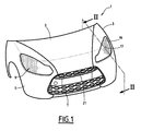
- the front block 1 shown on the figure 1 comprises a cover 3, two wings 5 arranged on the right and left of the cover 3, a shell 7, projectors 9 and means 11 for centering and holding in position each projector relative to the wings 5.
- the means 11 are visible on the figure 2 .
- each projector comprises a housing 13 having a opening opening towards the front, a window 15 integral with the housing, and one or more light sources (not shown) disposed inside the housing 13. the orifice of the housing 13.
- Each of the two wings 5 has an opening 17 provided to receive the ice 15 of one of the projectors.
- Each of the openings 17 is delimited by a peripheral edge 19 with a closed contour.
- Each opening 17 is entirely formed in the corresponding wing 5.
- the shell 7 is disposed vertically under the front edge 21 of the hood. It extends from one wing 5 to the other.
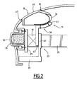
- the front block 1 further comprises a front face 23, visible on the figure 2 .
- the front face 23 comprises a rigid support structure and a plurality of equipment rigidly fixed to this structure. This equipment includes the radiator of the engine cooling circuit, a group motor-fan capable of creating a forced convection of air in contact with the radiator, the horn, one or more sensors parking assist, elements of the ventilation circuit and air conditioning of the passenger compartment, etc.
- the front face 23 is provided to be fixed on the two longitudinal members 25 of the vehicle.
- the rigid structure comprises in particular a transverse cross member 27 having two opposite end portions, rigidly attached to the two right and left side members of the vehicle. It also comprises a transverse bumper beam arranged at the front of the crossbar 27, and shock absorbers 31 of "repairability interposed longitudinally between the cross member 27 and the beam 29.
- The" repairability "shock absorbers are provided to dampen shocks on another vehicle at medium speed, that is to say at a speed of about 16 kilometers per hour.
- the front face also comprises an absorber 33 adapted to damp the leg-type pedestrian impact shock absorber 33 is a hollow section of plastic, extending transversely. This absorber is rigidly fixed on one face of the bumper beam 29 facing forward.
- the front face may optionally comprise a bar 35 of plastic foam housed inside the shock absorber 33.
- the front face 23 also includes another absorber 37 provided for cushioning pedestrian shocks of the leg type, integral with the crossbar 27.
- This absorber called "low path” has the shape of a substantially horizontal plate, typically made of plastic foam material . It is located under the bumper beam.
- the means 11 for centering and holding in position each projector 9 relative to the corresponding wing 5 comprises a flexible arm 39 rigidly fixed only to the projector 9 and to a structural element of the vehicle.
- the arm 39 is rigidly fixed by a first end portion 41 to the housing 13 of the projector. It is rigidly fixed by a second end portion 43 to the cross member 27 of the front face.
- the arm 39 is attached to a single point of the front block. It is not rigidly attached to the wing, nor to any other element of the front block.
- the projector housing is rigidly fixed only to the flexible arm 39.
- the projector is not rigidly attached to the wing or to any other element of the front block.
- the flexible arm 39 is shaped so as to urge the projector 9 against a bearing zone of the wing 5.
- the bearing zone is the peripheral edge 19 of the opening.
- the edge 19 is for example bevelled, in a direction such that the section of the opening 17 increases when going from the outside to the inside of the wing.
- the window 15 has a visible face 45 intended to fit into the opening 17, surrounded by a bearing area 47.
- the bearing area 47 has a shape conjugate with that of the peripheral edge 19 and is intended to bear against the beveled edge 19 under the effect of the bias applied by the arm 39.
- the force with which the housing is pressed on the peripheral edge 19 by the arm 39 is between 5 and 50 newton, and preferably between 20 and 30 newton.
- the arm 39 is made of a plastic material, or a metallic material, or comprises a metal core and a plastic material overmolded on the metal core.
- the flexibility of the arm 39 is chosen so that, in the event of a pedestrian impact, when, for example, the pedestrian's hip strikes the projector, the arm bends elastically and / or plastically under the effect of the impact. Thus, the projector tends to sink and is no longer a hard point that can hurt the pedestrian.
- the front block described above has many advantages.
- the means for centering and holding the projector in position relative to the body member comprises a flexible arm rigidly fixed only to the structural member and the projector, the projector being rigidly attached only to the flexible arm, the arm flexible being able to urge the projector against a bearing area of the bodywork element, the projector is no longer a hard point in case of pedestrian impact, as indicated above.
- the edge of the opening and the projector cooperate to ensure the centering of the projector relative to the wing in a very simple manner, under the effect of the bias applied by the flexible arm to the projector.
- the projector is almost self-centered.
- the projector contributes to maintaining in position wing relative to surrounding parts (hood, opening, grille).
- the projector also contributes to give the wing a curve, due to the force exerted by the elastic arm and transmitted by the projector.
- Games and outcrops between the wing and the mirror of the headlamp are considerably improved because the headlamp and the wing self center automatically relative to each other. It is thus possible to remove many expensive and complex accessories that are normally used to improve the games and outcrops.
- the edge of the aperture and the projector cooperate to adjust the level of the projector's ice relative to the wing, so that the ice is flush with the extension of the wing. In the same way, the edge of the opening and the projector cooperate to obtain a contact with a minimum clearance between said edge and the ice.
- the front block described above can have multiple variants.
- the flexible arm may not be rigidly attached to the cross member 27 but to another structural element of the vehicle. It may for example be attached to the bumper beam 29.
- the body member is not necessarily a wing but could be any other element of the vehicle body.
- the bearing zone against which the headlight comes under the effect of the bias and the flexible arm is not the peripheral edge of the opening, but is another zone of the element of body. This other zone may be located away from the opening 17. It may consist of a continuous surface or of several discrete surfaces and distant from each other.
- the opening provided to receive the projector glass may not be entirely formed in the same bodywork element, typically in the wing. It can be formed essentially in the wing and, for a small part, for example in the hood.
Description
La présente invention concerne en général un bloc avant de véhicule automobile.The present invention generally relates to a front block of a motor vehicle.
Plus précisément, l'invention concerne un bloc avant du type comprenant :
- un projecteur muni d'une glace ;
- un élément de structure ;
- un élément de carrosserie dans lequel est ménagé une ouverture prévue pour recevoir la glace du projecteur ;
- des moyens pour centrer et maintenir en position le projecteur par rapport à l'élément de carrosserie.
- a projector with an ice cream;
- a structural element;
- a bodywork element in which is provided an opening for receiving the projector glass;
- means for centering and holding the projector in position relative to the body member.
La publication
On connaît de
Dans ce contexte, l'invention vise à proposer un bloc avant permettant de garantir une meilleure sécurité pour les piétons.In this context, the invention aims to provide a front block to ensure greater safety for pedestrians.
A cette fin, l'invention porte sur un bloc avant du type précité, caractérisé en ce que les moyens pour centrer et maintenir en position le projecteur par rapport à l'élément de carrosserie comprennent un bras flexible rigidement fixé seulement à l'élément de structure et au projecteur, le projecteur étant rigidement fixé seulement au bras flexible, le bras flexible étant apte à solliciter le projecteur contre une zone d'appui de l'élément de carrosserie.To this end, the invention relates to a front block of the aforementioned type, characterized in that the means for centering and holding the projector in position relative to the bodywork element comprise a flexible arm rigidly fixed only to the element of structure and projector, the projector being rigidly fixed only to the flexible arm, the flexible arm being adapted to urge the projector against a bearing area of the bodywork element.
Le bloc avant peut également présenter une ou plusieurs des caractéristiques ci-dessous, considérées individuellement ou selon toutes les combinaisons techniquement possibles :
- la zone d'appui est un bord de l'ouverture, le bord de l'ouverture et le projecteur étant aptes à coopérer en vue d'assurer le centrage du projecteur par rapport à l'élément de carrosserie sous l'effet de la sollicitation appliquée par le bras flexible au projecteur ;
- l'élément de carrosserie est une aile du véhicule ;
- l'ouverture est délimitée par un bord à contour fermé et est entièrement ménagée dans l'élément de carrosserie ;
- l'élément de structure est une traverse ; et
- le bras flexible est apte à solliciter le projecteur contre la zone d'appui de l'élément de carrosserie avec une force comprise entre 5 et 50 newtons.
- the bearing zone is an edge of the opening, the edge of the opening and the projector being capable of cooperating in order to ensure the centering of the headlight with respect to the bodywork element under the effect of the solicitation applied by the flexible arm to the projector;
- the body member is a wing of the vehicle;
- the opening is delimited by a closed contour edge and is entirely formed in the bodywork element;
- the structural element is a cross; and
- the flexible arm is able to urge the projector against the bearing area of the bodywork element with a force of between 5 and 50 newtons.
D'autres caractéristiques et avantages de l'invention ressortiront de la description détaillée qui en est donnée ci-dessous, à titre indicatif et nullement limitatif, en référence aux figures annexées, parmi lesquelles :
- la
figure 1 est une vue en perspective d'un bloc avant conforme à l'invention ; et - la
figure 2 est une vue en coupe du bloc avant de lafigure 1 , considérée suivant l'incidence des flèches II-II.
- the
figure 1 is a perspective view of a front block according to the invention; and - the
figure 2 is a sectional view of the front block of thefigure 1 , considered according to the incidence of arrows II-II.
Dans la description qui va suivre, l'avant, l'arrière, la droite et la gauche, les directions longitudinales et transversales seront entendues relativement au sens de déplacement normal du véhicule.In the following description, the front, the rear, the right and the left, the longitudinal and transverse directions will be heard relative to the direction of normal movement of the vehicle.
Le bloc avant 1 représenté sur la
Comme le montre la
Chacune des deux ailes 5 comporte une ouverture 17 prévue pour recevoir la glace 15 d'un des projecteurs. Chacune des ouvertures 17 est délimitée par un bord périphérique 19 à contour fermé. Chaque ouverture 17 est entièrement ménagée dans l'aile 5 correspondante.Each of the two
La calandre 7 est disposée verticalement sous le bord avant 21 du capot. Elle s'étend d'une aile 5 à l'autre.The
Le bloc avant 1 comporte par ailleurs une face avant 23, visible sur la
La structure rigide comporte notamment une traverse transversale 27 présentant deux parties d'extrémités opposées, rigidement fixées aux deux longerons droit et gauche du véhicule. Elle comporte également une poutre de pare-chocs 29 transversale disposée à l'avant de la traverse 27, et des absorbeurs de chocs 31 de type « réparabilité interposés longitudinalement entre la traverse 27 et la poutre 29. Les absorbeurs de chocs « réparabilité » sont prévus pour amortir des chocs sur un autre véhicule à vitesse moyenne, c'est-à-dire à une vitesse d'environ 16 kilomètres par heure.The rigid structure comprises in particular a
La face avant comporte également un absorbeur 33 adapté pour amortir les chocs piétons de type jambes L'absorbeur de chocs 33 est un profilé creux en matière plastique, s'étendant transversalement. Cet absorbeur est rigidement fixé sur une face de la poutre de pare-chocs 29 tournée vers l'avant. La face avant peut éventuellement comporter une barre 35 de mousse de matière plastique logée à l'intérieur de l'absorbeur de chocs 33.The front face also comprises an
La face avant 23 comprend également un autre absorbeur 37 prévu pour amortir les chocs piétons du type jambes, solidaire de la traverse 27. Cet absorbeur dit « voie basse » présente la forme d'un plateau sensiblement horizontal, réalisé typiquement en mousse de matériau plastique. Il est situé sous la poutre de pare-chocs.The
Comme le montre la
Par ailleurs, le boîtier de projecteur est rigidement fixé seulement au bras flexible 39. Le projecteur n'est pas rigidement fixé à l'aile, ni à aucun autre élément du bloc avant.Furthermore, the projector housing is rigidly fixed only to the
Le bras flexible 39 est conformé de manière à solliciter le projecteur 9 contre une zone d'appui de l'aile 5.The
De préférence, la zone d'appui est le bord périphérique 19 de l'ouverture. Le bord 19 est par exemple biseauté, dans un sens tel que la section de l'ouverture 17 augmente quand on passe de l'extérieur à l'intérieur de l'aile.Preferably, the bearing zone is the
La glace 15 présente une face visible 45 destinée à s'inscrire dans l'ouverture 17, entourée par une zone de portée 47. La zone de portée 47 présente une forme conjuguée de celle du bord périphérique 19 et est destinée à venir en appui contre le bord biseauté 19 sous l'effet de la sollicitation appliquée par le bras 39. La force avec laquelle le boîtier est appuyé sur le bord périphérique 19 par le bras 39 est comprise entre 5 et 50 newton, et de préférence comprise entre 20 et 30 newton.The
Le bras 39 est réalisé en une matière plastique, ou en une matière métallique, ou comprend une âme métallique et une matière plastique surmoulée sur l'âme métallique. La flexibilité du bras 39 est choisie de telle sorte que, en cas de choc piéton, quand, par exemple, la hanche du piéton vient heurter le projecteur, le bras se plie élastiquement et/ou plastiquement sous l'effet du choc. Ainsi, le projecteur tend à s'enfoncer et ne constitue plus un point dur pouvant blesser le piéton.The
Le bloc avant décrit ci-dessus présente de multiples avantages.The front block described above has many advantages.
Du fait que les moyens pour centrer et maintenir en position le projecteur par rapport à l'élément de carrosserie comprennent un bras flexible rigidement fixé seulement à l'élément de structure et au projecteur, le projecteur étant rigidement fixé seulement au bras flexible, le bras flexible étant apte à solliciter le projecteur contre une zone d'appui de l'élément de carrosserie, le projecteur ne constitue plus un point dur en cas de choc piéton, comme indiqué ci-dessus.Because the means for centering and holding the projector in position relative to the body member comprises a flexible arm rigidly fixed only to the structural member and the projector, the projector being rigidly attached only to the flexible arm, the arm flexible being able to urge the projector against a bearing area of the bodywork element, the projector is no longer a hard point in case of pedestrian impact, as indicated above.
Par ailleurs, le bord de l'ouverture et le projecteur coopèrent de manière à assurer le centrage du projecteur par rapport à l'aile de manière très simple, sous l'effet de la sollicitation appliquée par le bras flexible au projecteur. Le projecteur est pour ainsi dire auto centré.Furthermore, the edge of the opening and the projector cooperate to ensure the centering of the projector relative to the wing in a very simple manner, under the effect of the bias applied by the flexible arm to the projector. The projector is almost self-centered.
De plus, quand l'aile est réalisée dans un matériau présentant une certaine flexibilité, par exemple en un métal souple ou dans une matière plastique technique connue sous le nom de Xenoy ou Noryl ou encore en polypropylène, le projecteur contribue à maintenir en position l'aile par rapport aux pièces avoisinantes (capot, ouvrant, calandre). Le projecteur contribue également à conférer à l'aile un galbe, du fait de l'effort exercé par le bras élastique et transmis par le projecteur.In addition, when the wing is made of a material having a certain flexibility, for example a flexible metal or a plastic plastic known as Xenoy or Noryl or polypropylene, the projector contributes to maintaining in position wing relative to surrounding parts (hood, opening, grille). The projector also contributes to give the wing a curve, due to the force exerted by the elastic arm and transmitted by the projector.
Les jeux et affleurements entre l'aile et la glace du projecteur sont considérablement améliorés du fait que le projecteur et l'aile s'auto centrent automatiquement l'un par rapport à l'autre. Il est ainsi possible de supprimer de nombreux accessoires onéreux et complexes qui sont normalement utilisés pour améliorer les jeux et affleurements. Le bord de l'ouverture et le projecteur coopèrent pour ajuster le niveau de la glace du projecteur par rapport à l'aile, de telle sorte que la glace affleure dans le prolongement de l'aile. De la même façon, le bord de l'ouverture et le projecteur coopèrent pour obtenir un contact avec un jeu minimum entre ledit bord et la glace.Games and outcrops between the wing and the mirror of the headlamp are considerably improved because the headlamp and the wing self center automatically relative to each other. It is thus possible to remove many expensive and complex accessories that are normally used to improve the games and outcrops. The edge of the aperture and the projector cooperate to adjust the level of the projector's ice relative to the wing, so that the ice is flush with the extension of the wing. In the same way, the edge of the opening and the projector cooperate to obtain a contact with a minimum clearance between said edge and the ice.
Le bloc avant décrit ci-dessus peut présenter de multiples variantes.The front block described above can have multiple variants.
Le bras flexible peut ne pas être rigidement fixé à la traverse 27 mais à un autre élément de structure du véhicule. Il peut par exemple être fixé à la poutre de pare-chocs 29. L'élément de carrosserie n'est pas nécessairement une aile mais pourrait être tout autre élément de la carrosserie du véhicule.The flexible arm may not be rigidly attached to the
Dans une variante non préférée, la zone d'appui contre laquelle le projecteur vient porter sous l'effet de la sollicitation et du bras flexible n'est pas le bord périphérique de l'ouverture, mais est une autre zone de l'élément de carrosserie. Cette autre zone peut être située à distance de l'ouverture 17. Elle peut être constituée d'une surface continue ou de plusieurs surfaces discrètes et éloignées les unes des autres.In a non preferred variant, the bearing zone against which the headlight comes under the effect of the bias and the flexible arm is not the peripheral edge of the opening, but is another zone of the element of body. This other zone may be located away from the
L'ouverture prévue pour recevoir la glace du projecteur peut ne pas être ménagée entièrement dans un même élément de carrosserie, typiquement dans l'aile. Elle peut être ménagée essentiellement dans l'aile et, pour une faible partie, par exemple dans le capot.The opening provided to receive the projector glass may not be entirely formed in the same bodywork element, typically in the wing. It can be formed essentially in the wing and, for a small part, for example in the hood.
Claims (6)
- Front block of an automotive vehicle, which front block (1) comprises:- a headlamp (9) fitted with a glass plate (15);- a structure element (27);- a body element (5) in which an orifice (17) for receiving the glass plate (15) of the headlamp (9) is provided;- means (11) for centring and holding the headlamp (9) in position relative to the body element (5); and holdingcharacterised in that the means (11) for centring and holding the headlamp (9) in position relative to the body element (5) comprise a flexible arm (39) rigidly secured to only the structure element (27) and to the headlamp (9), the headlamp (9) being rigidly secured to the flexible arm only (39), the flexible arm (39) being designed to bias the headlamp (9) against a support zone (19) on the body element (5).
- Front block as claimed in claim 1, characterised in that the support zone (19) is an edge of the orifice (17), the edge (19) of the orifice (17) and the headlamp (9) being designed to co-operate to ensure that the headlamp (9) is centred relative to the body element (5) due to the biasing action of the flexible arm (39) applied to the headlamp (9).
- Front block as claimed in claim 1 or 2, characterised in that the body element (5) is a wing of the vehicle.
- Front block as claimed in claim 3, characterised in that the orifice (17) is bounded by an edge (19) with a closed contour and is incorporated entirely within the body element (5).
- Front block as claimed in any one of claims 1 to 4, characterised in that the structure element (27) is a cross-member.
- Front block as claimed in any one of claims 1 to 5, characterised in that the flexible arm (39) is designed to bias the headlamp (9) against the support zone (19) of the body element (5) with a force of between 5 and 50 newtons.
Applications Claiming Priority (1)
| Application Number | Priority Date | Filing Date | Title |
|---|---|---|---|
| FR0850353A FR2926525B1 (en) | 2008-01-21 | 2008-01-21 | FRONT BLOCK OF MOTOR VEHICLE WITH SELF-CENTER PROJECTOR |
Publications (2)
| Publication Number | Publication Date |
|---|---|
| EP2080666A1 EP2080666A1 (en) | 2009-07-22 |
| EP2080666B1 true EP2080666B1 (en) | 2010-12-01 |
Family
ID=39714021
Family Applications (1)
| Application Number | Title | Priority Date | Filing Date |
|---|---|---|---|
| EP09150293A Expired - Fee Related EP2080666B1 (en) | 2008-01-21 | 2009-01-09 | Front block of an automobile with self-centring headlight |
Country Status (4)
| Country | Link |
|---|---|
| EP (1) | EP2080666B1 (en) |
| DE (1) | DE602009000376D1 (en) |
| ES (1) | ES2355197T3 (en) |
| FR (1) | FR2926525B1 (en) |
Families Citing this family (1)
| Publication number | Priority date | Publication date | Assignee | Title |
|---|---|---|---|---|
| FR3032513B1 (en) * | 2015-02-11 | 2018-07-06 | Psa Automobiles Sa. | ARRANGEMENT OF AN ICE-FREE VEHICLE PROJECTOR ON A VEHICLE |
Family Cites Families (3)
| Publication number | Priority date | Publication date | Assignee | Title |
|---|---|---|---|---|
| FR2844755B1 (en) * | 2002-09-20 | 2007-02-16 | Valeo Vision | MOTOR VEHICLE PROJECTOR COMPRISING A DAMPING SYSTEM |
| FR2888197B1 (en) | 2005-07-08 | 2007-10-12 | Faurecia Bloc Avant | FRONT BLOCK ASSEMBLY OF A CORRESPONDING MOTOR VEHICLE. |
| FR2893902B1 (en) * | 2005-11-28 | 2009-01-09 | Plastic Omnium Cie | PIECE OF A MOTOR VEHICLE COMPRISING MEANS FOR SUPPORTING AN OPTICAL BLOCK. |
-
2008
- 2008-01-21 FR FR0850353A patent/FR2926525B1/en not_active Expired - Fee Related
-
2009
- 2009-01-09 DE DE602009000376T patent/DE602009000376D1/en active Active
- 2009-01-09 ES ES09150293T patent/ES2355197T3/en active Active
- 2009-01-09 EP EP09150293A patent/EP2080666B1/en not_active Expired - Fee Related
Also Published As
| Publication number | Publication date |
|---|---|
| DE602009000376D1 (en) | 2011-01-13 |
| FR2926525A1 (en) | 2009-07-24 |
| FR2926525B1 (en) | 2010-04-02 |
| ES2355197T3 (en) | 2011-03-23 |
| EP2080666A1 (en) | 2009-07-22 |
Similar Documents
| Publication | Publication Date | Title |
|---|---|---|
| EP2173602B1 (en) | Front face of automobile with crossbar at the main rails | |
| EP2384938B1 (en) | Back end for a vehicle | |
| FR3010037A1 (en) | VEHICLE COMPRISING A DEFLECTOR DEVICE AND DEFLECTING DEVICE | |
| FR2914900A1 (en) | AUTOMOTIVE VEHICLE DASHBOARD TRAILER AND CORRESPONDING MOTOR VEHICLE. | |
| FR2931417A1 (en) | SHOCK ABSORPTION DEVICE AND FRONT PANEL COMPRISING SUCH A DEVICE | |
| EP1878621A1 (en) | Bumper of an automobile vehicle, in particular for a station-wagon type vehicle | |
| EP2057040B1 (en) | Bumper for an automotive vehicle comprising staggered bumper stiffeners | |
| EP2080666B1 (en) | Front block of an automobile with self-centring headlight | |
| FR3034383B1 (en) | ANTI-CAPOTAGE SYSTEM FOR A MOTOR VEHICLE | |
| WO2008061824A1 (en) | Impact-absorbing assembly for a motor vehicle and corresponding front panel | |
| EP2322413A1 (en) | Front crossbeam of an automobile including a rear fairing element | |
| FR2931418A1 (en) | Adjustable device i.e. armature, for mounting bumper on body shell of automobile, has transversal section placed along rolling axis of vehicle, and rigidification units placed inside section to limit deformation of bumper during shock | |
| EP2207709B1 (en) | Automobile comprising a crossbar, a technical front surface and a convergent element attached to each other | |
| EP2165890B1 (en) | Reinforcing part and vehicle comprising such a part. | |
| FR3111615A1 (en) | Connection reinforcement between a front leg of a motor vehicle and a stretcher line of said motor vehicle | |
| FR3105152A1 (en) | LOW COVER IMPACT REINFORCEMENT | |
| EP1762439A1 (en) | Motor vehicle bumper beam | |
| EP2058211B1 (en) | Front bonnet of an automobile | |
| FR3083755A1 (en) | AIR GUIDE FOR A MOTOR VEHICLE MADE OF A PART OF EXPANDED POLYMER MATERIAL COMPRISING SHOCK ABSORBING AREAS | |
| EP2925591B1 (en) | Support strucutre for a front wing of a car and car with such a support structure | |
| FR2946607A1 (en) | MID FOOT FOR BODY OF AUTOMOTIVE VEHICLE, STRENGTHENED WITH REGARD TO SHOCK SHOCKS AND VEHICLE EQUIPPED WITH SUCH FEET MIDDLE. | |
| FR2945001A1 (en) | AUTOMOTIVE VEHICLE SIDE DOOR COMPRISING A BAND TO INCREASE THE RESISTANCE OF THE DOOR TO LATERAL SHOCKS AND VEHICLE EQUIPPED WITH SUCH A DOOR | |
| EP3372478B1 (en) | Front panel part of a motor vehicle located in a collosion area integrated a rigid housing | |
| EP2251232A1 (en) | Front bumper structure of an automobile including transversely distributed absorption elements | |
| WO2022254114A1 (en) | Bracket for attaching two vehicle devices |
Legal Events
| Date | Code | Title | Description |
|---|---|---|---|
| PUAI | Public reference made under article 153(3) epc to a published international application that has entered the european phase |
Free format text: ORIGINAL CODE: 0009012 |
|
| AK | Designated contracting states |
Kind code of ref document: A1 Designated state(s): AT BE BG CH CY CZ DE DK EE ES FI FR GB GR HR HU IE IS IT LI LT LU LV MC MK MT NL NO PL PT RO SE SI SK TR |
|
| AX | Request for extension of the european patent |
Extension state: AL BA RS |
|
| RIN1 | Information on inventor provided before grant (corrected) |
Inventor name: RIVIERE, CAROLINE Inventor name: GONIN, VINCENT |
|
| 17P | Request for examination filed |
Effective date: 20100111 |
|
| AKX | Designation fees paid |
Designated state(s): DE ES FR GB IT |
|
| GRAC | Information related to communication of intention to grant a patent modified |
Free format text: ORIGINAL CODE: EPIDOSCIGR1 |
|
| GRAP | Despatch of communication of intention to grant a patent |
Free format text: ORIGINAL CODE: EPIDOSNIGR1 |
|
| GRAS | Grant fee paid |
Free format text: ORIGINAL CODE: EPIDOSNIGR3 |
|
| GRAA | (expected) grant |
Free format text: ORIGINAL CODE: 0009210 |
|
| AK | Designated contracting states |
Kind code of ref document: B1 Designated state(s): DE ES FR GB IT |
|
| REG | Reference to a national code |
Ref country code: GB Ref legal event code: FG4D Free format text: NOT ENGLISH |
|
| REF | Corresponds to: |
Ref document number: 602009000376 Country of ref document: DE Date of ref document: 20110113 Kind code of ref document: P |
|
| REG | Reference to a national code |
Ref country code: ES Ref legal event code: FG2A Ref document number: 2355197 Country of ref document: ES Kind code of ref document: T3 Effective date: 20110323 |
|
| PLBE | No opposition filed within time limit |
Free format text: ORIGINAL CODE: 0009261 |
|
| STAA | Information on the status of an ep patent application or granted ep patent |
Free format text: STATUS: NO OPPOSITION FILED WITHIN TIME LIMIT |
|
| 26N | No opposition filed |
Effective date: 20110902 |
|
| REG | Reference to a national code |
Ref country code: DE Ref legal event code: R097 Ref document number: 602009000376 Country of ref document: DE Effective date: 20110902 |
|
| REG | Reference to a national code |
Ref country code: FR Ref legal event code: PLFP Year of fee payment: 8 |
|
| REG | Reference to a national code |
Ref country code: FR Ref legal event code: PLFP Year of fee payment: 9 |
|
| PGFP | Annual fee paid to national office [announced via postgrant information from national office to epo] |
Ref country code: GB Payment date: 20161228 Year of fee payment: 9 |
|
| PGFP | Annual fee paid to national office [announced via postgrant information from national office to epo] |
Ref country code: ES Payment date: 20161222 Year of fee payment: 9 Ref country code: FR Payment date: 20161221 Year of fee payment: 9 |
|
| PGFP | Annual fee paid to national office [announced via postgrant information from national office to epo] |
Ref country code: DE Payment date: 20161219 Year of fee payment: 9 |
|
| PGFP | Annual fee paid to national office [announced via postgrant information from national office to epo] |
Ref country code: IT Payment date: 20170103 Year of fee payment: 9 |
|
| REG | Reference to a national code |
Ref country code: DE Ref legal event code: R119 Ref document number: 602009000376 Country of ref document: DE |
|
| GBPC | Gb: european patent ceased through non-payment of renewal fee |
Effective date: 20180109 |
|
| PG25 | Lapsed in a contracting state [announced via postgrant information from national office to epo] |
Ref country code: FR Free format text: LAPSE BECAUSE OF NON-PAYMENT OF DUE FEES Effective date: 20180131 Ref country code: DE Free format text: LAPSE BECAUSE OF NON-PAYMENT OF DUE FEES Effective date: 20180801 |
|
| REG | Reference to a national code |
Ref country code: FR Ref legal event code: ST Effective date: 20180928 |
|
| PG25 | Lapsed in a contracting state [announced via postgrant information from national office to epo] |
Ref country code: GB Free format text: LAPSE BECAUSE OF NON-PAYMENT OF DUE FEES Effective date: 20180109 |
|
| PG25 | Lapsed in a contracting state [announced via postgrant information from national office to epo] |
Ref country code: IT Free format text: LAPSE BECAUSE OF NON-PAYMENT OF DUE FEES Effective date: 20180109 |
|
| REG | Reference to a national code |
Ref country code: ES Ref legal event code: FD2A Effective date: 20190730 |
|
| PG25 | Lapsed in a contracting state [announced via postgrant information from national office to epo] |
Ref country code: ES Free format text: LAPSE BECAUSE OF NON-PAYMENT OF DUE FEES Effective date: 20180110 |